EP2139071B1 - Adaptive Gruppenantenne-Sende/Empfangsvorrichtung - Google Patents
Adaptive Gruppenantenne-Sende/Empfangsvorrichtung Download PDFInfo
- Publication number
- EP2139071B1 EP2139071B1 EP09172379A EP09172379A EP2139071B1 EP 2139071 B1 EP2139071 B1 EP 2139071B1 EP 09172379 A EP09172379 A EP 09172379A EP 09172379 A EP09172379 A EP 09172379A EP 2139071 B1 EP2139071 B1 EP 2139071B1
- Authority
- EP
- European Patent Office
- Prior art keywords
- signal
- calibration
- frequency
- receiver
- switch
- Prior art date
- Legal status (The legal status is an assumption and is not a legal conclusion. Google has not performed a legal analysis and makes no representation as to the accuracy of the status listed.)
- Expired - Lifetime
Links
Images


Classifications
-
- H—ELECTRICITY
- H01—ELECTRIC ELEMENTS
- H01Q—ANTENNAS, i.e. RADIO AERIALS
- H01Q21/00—Antenna arrays or systems
-
- H—ELECTRICITY
- H01—ELECTRIC ELEMENTS
- H01Q—ANTENNAS, i.e. RADIO AERIALS
- H01Q3/00—Arrangements for changing or varying the orientation or the shape of the directional pattern of the waves radiated from an antenna or antenna system
- H01Q3/26—Arrangements for changing or varying the orientation or the shape of the directional pattern of the waves radiated from an antenna or antenna system varying the relative phase or relative amplitude of energisation between two or more active radiating elements; varying the distribution of energy across a radiating aperture
- H01Q3/2605—Array of radiating elements provided with a feedback control over the element weights, e.g. adaptive arrays
-
- H—ELECTRICITY
- H01—ELECTRIC ELEMENTS
- H01Q—ANTENNAS, i.e. RADIO AERIALS
- H01Q3/00—Arrangements for changing or varying the orientation or the shape of the directional pattern of the waves radiated from an antenna or antenna system
- H01Q3/26—Arrangements for changing or varying the orientation or the shape of the directional pattern of the waves radiated from an antenna or antenna system varying the relative phase or relative amplitude of energisation between two or more active radiating elements; varying the distribution of energy across a radiating aperture
- H01Q3/267—Phased-array testing or checking devices
-
- H—ELECTRICITY
- H04—ELECTRIC COMMUNICATION TECHNIQUE
- H04B—TRANSMISSION
- H04B17/00—Monitoring; Testing
- H04B17/10—Monitoring; Testing of transmitters
- H04B17/11—Monitoring; Testing of transmitters for calibration
- H04B17/12—Monitoring; Testing of transmitters for calibration of transmit antennas, e.g. of the amplitude or phase
-
- H—ELECTRICITY
- H04—ELECTRIC COMMUNICATION TECHNIQUE
- H04B—TRANSMISSION
- H04B17/00—Monitoring; Testing
- H04B17/20—Monitoring; Testing of receivers
- H04B17/21—Monitoring; Testing of receivers for calibration; for correcting measurements
- H04B17/22—Monitoring; Testing of receivers for calibration; for correcting measurements for calibration of the receiver components
- H04B17/221—Monitoring; Testing of receivers for calibration; for correcting measurements for calibration of the receiver components of receiver antennas, e.g. as to amplitude or phase
-
- H—ELECTRICITY
- H04—ELECTRIC COMMUNICATION TECHNIQUE
- H04B—TRANSMISSION
- H04B7/00—Radio transmission systems, i.e. using radiation field
- H04B7/02—Diversity systems; Multi-antenna system, i.e. transmission or reception using multiple antennas
- H04B7/04—Diversity systems; Multi-antenna system, i.e. transmission or reception using multiple antennas using two or more spaced independent antennas
- H04B7/06—Diversity systems; Multi-antenna system, i.e. transmission or reception using multiple antennas using two or more spaced independent antennas at the transmitting station
- H04B7/0613—Diversity systems; Multi-antenna system, i.e. transmission or reception using multiple antennas using two or more spaced independent antennas at the transmitting station using simultaneous transmission
- H04B7/0615—Diversity systems; Multi-antenna system, i.e. transmission or reception using multiple antennas using two or more spaced independent antennas at the transmitting station using simultaneous transmission of weighted versions of same signal
- H04B7/0617—Diversity systems; Multi-antenna system, i.e. transmission or reception using multiple antennas using two or more spaced independent antennas at the transmitting station using simultaneous transmission of weighted versions of same signal for beam forming
Definitions
- FIG. 34 An apparatus combining an adaptive array antenna and an FDD system is formed as shown in Fig. 34 .
- the calibration circuit for such a conventional example is shown in Fig. 33 .
- the calibration procedure in the case of using the calibration circuit shown in Fig. 33 is -as follows:
- the transmission signal from the transmitter provided on any one of the branches of the array antenna can be input into the transmitter of any one of the branches after it matches the frequency.
- the calibration control circuit selects in sequence the signals output from the respective plurality of transmitters by the first switch, and at the same time, controls the second switch and the third switch, inputs the signal that has been frequency converted by the frequency converter into the receiver of the particular branch assigned in advance to serve as a reference, and calculates, as the calibration value of the transmission system of each of the branches, a amplitude and phase ration between the plurality of values measured at the transceiver of each branches and the values measured at the transceiver of the particular branch assigned in advance to serve as the reference.
- the components of the transmitter, the components of the receiver, and the components dependent temperature characteristics are included in the amplitude and phase values that are obtained by detecting the signal output by the transmitter at the receiver. Because the ratio of the amplitude and phase values obtained by measuring the signals from the transmitter of each of the branches at a particular receiver to the amplitude and phase values obtained by measuring a signal from the transmitter of the branch serving as the reference is found, the components of the common receivers and the components of the temperature characteristics are offset in the amplitude and phase values of each of the branches are cancelled, and the components of the amplitude and phase values of only the transmitters can be obtained as calibration values.
- the calibration circuit selects a signal output by the transmitter of a particular branch assigned in advance to serve as a reference, and at the same time, by controlling the second switch and the third switch, the signals that have been frequency converted by the frequency converter are input in sequence into the receiver of each of the branches, and calculates, as the calibration value of the reception system of each of the branches, a amplitude and phase ration between the plurality of values measured at the receiver of each branches and the values measured at the receiver of the particular branch assigned in advance to serve as the reference.
- the frequency of the signal output by the local signal generator corresponds to the difference between the reception frequency of the receiver and the transmission frequency.
- the transmission frequency of the signal applied to the antenna elements is f1
- the reception frequency of the receiver is f2
- the relationship between these frequencies is f1 > f2
- the frequency of the signal output by the local signal generator becomes f1 - f2.
- the second switch extracts from the output of the transmitter of one branch the signal before conversion by the first frequency converter using the second branching device, and selectively outputs this to one of the plurality of paths corresponding to the plurality of receivers.
- the third switch selectively inputs into each receiver the reception signal from the antenna elements, the signal from the second switch, and the signal from the second frequency converter.
- the calibration control circuit carries out the control of the first switch, the second switch, and the third switch.
- the calibration control circuit inputs the amplitude and phase values obtained at the receiver and finds the calibration value of each of the branches of the array antenna.
- the second aspect of the adaptive array antenna transceiver apparatus can carry out calibration of the transmitter without calibrating the receiver because the amplitude and phase values can be measured by inputting the signals output by the transmitter to the receiver even in the case that the reception frequency and the transmitting frequency are different.
- the calibration control circuit selects in sequence signals output from each of the plurality of transmitters using the first switch, and at the same time, controls the second switch and the third switch, inputs into the receiver of a particular branch assigned in advance to serve as a reference signal a signal that has been frequency converted by the second frequency converter, and calculates as the calibration value of the transmitter system of each of the branches the ratio of the plurality of the amplitude and phase values measured for the respective signals from the transmitters of each of the branches to the amplitude and phase values measured for the signal from the transmitter of a particular branch assigned in advance to serve as a reference.
- the calibration control circuit extracts the signals output by the transmitter of a particular branch assigned in advance to serve as the reference using the second branching device, inputs these in sequence to the receivers of each of the branches via the second switch and the third switch, and calculates as the calibration value of the reception system of each of the branches the ratio of the plurality of amplitude and phase values measured at the respective receivers of each of the branches and the amplitude and phase values measured at the receiver of the particular branch assigned in advance to serve as the reference.
- an adaptive array transceiver apparatus providing an array antenna comprising a plurality of antenna elements, transmitters and receivers in the same number as the antenna elements of the array antenna, transmitter/receiver common-use devices connecting the respective transmitters and receivers to each of the antenna elements, and a radiation pattern control calculation circuit that controls the radiation pattern of the array antenna by synthesizing the output of the plurality of receivers by weighting the amplitude and phase with respect to a signal input from each respective antenna element to the plurality of receivers, and at the same time the reception frequency of the receivers is different from the transmitting frequency of the transmitters
- the present invention provides a local signal generator that outputs a signal having a frequency that corresponds to the difference between the reception frequency of the receivers and the transmitting frequency of the transmitters, a branching device that separates and extracts a part of the signals from the plurality respective of transmitters, a plurality of first switches that inputs and selects one of the output signals of the respective branching devices from two adjacent branches in the arrangement of the branches
- the frequency converter converts the frequencies of the signal selected by the first switch in each of the branches using the signal that the local signal generator outputs.
- the frequency of the signal output by the local signal generator corresponds to the difference between the reception frequency of the receiver and the transmission frequency of the transmitter.
- the transmission frequency of the transmitter is f1
- the reception frequency of the receiver is f2
- the relationship therebetween is (f1 > f2)
- the frequency of the signal output by the local signal generator is (f1 - f2). Therefore, when the signal output from the receiver and having a frequency of f1 is input into the frequency converter, a signal having a frequency of f2 is obtained at the output of the frequency converter.
- the frequency f2 of this signal is the same as the reception frequency f2 of the receivers, and thus if this signal is input into each of the receivers, the amplitude and phase of the signal can be measured at these receivers.
- the calibration control circuit alternately selects by the first switch the signals output by the transmitters of two adjacent branches at each of the adjacent branches, and at the same time, controls the second switch and the third switch, inputs the signal frequency converted by the frequency converter into one receiver assigned in advance among the two branches, finds as the first ratio the ratio of the respectively measured values of the amplitude and phase for the signals from the transmitters of the two branches, and at the same time, for branches other than the branch assigned in advance to serve as the reference, the first ratio found at the relevant branch is calibrated using the first ratio found at the other branches, and the calibration value of the transmitting system of each of the branches is calculated.
- the calibration control circuit selects the signal output by the one transmitter assigned in advance among two adjacent branches for each adjacent branch by the first switch, and at the same time, controls the second switch and the third switch, alternately inputs the signal that has been frequency converted by the frequency converter into each of the receivers of the two adjacent branches, and finds as a first ratio the ratio of a plurality of amplitude and phase values respectively measured at the receivers of two adjacent branches, and at the same time, for branches other than that assigned in advance to serve as the reference, the first ratio found at the relevant branch is calibrated using the first ratio found at the other branches, and the calibration value of the receiving system of each of the branches is calculated.
- the signal from one of the receivers is alternately selected at the second switch and input into one of the receivers, and thereby two amplitude and phase values are obtained.
- the ratio of these two amplitude and phase values serves as the first ratio.
- the first ratio is found for each of the respective adjacent branches.
- the first ratio of each of the branches is unified with the ratio of the amplitude and phase values of the receiver of the relevant branch with respect to the amplitude and phase value components of the receiver of the particular branch assigned to serve as the reference. Therefore, the first ratio of each of the branches can be used as a calibration value for the amplitude and phase value components of each of the receivers.
- the circuits of three branches are selected, and a signal transmitted from each of two branches can be received by the one common branch or the signal transmitted from the one common branch can be received by each of the two remaining branches.
- the calibration control circuit transmits the signal that is the signal transmitted from the first transmitter and frequency converted by the first frequency converter from the antenna element of the branch included in the first transmitter, inputs the output that is the signal from the first transmitter received by the additional antenna and frequency converted by the second frequency converter into the calibration receiver, and detects the first measured value obtained at the calibration receiver.
- the calibration control circuit transmits the signal that is the signal transmitted by the second transmitter and frequency converted by the first frequency converter from the antenna element of the branch included in the second transmitter, inputs the output that is the signal from the second transmitter received by the additional antenna and frequency converted by the second frequency converter into the calibration receiver, and detects a second measured value obtained at the calibration receiver.
- the calibration control circuit calculates as the first calibration value the ratio of the second measured value and the first measured value, and finds the respective first calibration values for the plurality of branches based on the respective first measured value and the second measured value by switching in sequence the selection of the first transmitter and the second transmitter.
- the first calibration value of the relevant branch is calibrated using the first calibration value obtained at the other branches, and the first calibration value is calculated as a relative value with respect to the reference branch.
- the calibration value for the amplitude and phase values of the transmitter that includes the transmitters and antenna elements of the respective branches can be found as a relative value with respect to a particular reference branch.
- the calibration control circuit controls the first switch, second switch, and third switch, and selects from among N receivers the first receiver and second receiver respectively included in branches of two antenna elements that have equal distances from the additional antenna, and at the same time, selects from among N transmitters one calibration transmitter included in a branch different from that of the first receiver and the second receiver.
- the calibration control circuit transmits a signal output by the calibration transmitter from the additional antenna via a branching device, a second transmitter/receiver common-use device, .a first switch and third switch, inputs the signal from the calibration transmitter received by the antenna element of the branch included in the first transmitter into the first receiver, and detects the first measured value obtained at the first receiver.
- the calibration control circuit inputs a signal from the calibration transmitter received by the antenna element of a branch included in the second receiver into the second receiver, and detects the second measured value obtained at the second receiver.
- the calibration value can be -found such that the influence of transmission loss between the antenna elements and the additional antenna does not appear.
- the antenna elements of the array antenna are disposed arranged on a circle, by disposing the additional antenna at the middle position of this circle, the distances between all the respective antenna elements and the additional antenna can be made equal.
- an adaptive array antenna transceiver apparatus providing an array antenna formed by N antenna elements, N is an integral number and shows two or more; N transmitters and receivers; a transmitter/receiver common-use device that connects the respective transmitters and receivers to each of the antenna elements; and a radiation pattern control processor that controls the radiation pattern of the array antenna by synthesizing the output of the plurality of receivers by weighting the amplitude and phase with respect to a signal input from each respective antenna element into the plurality of receivers, and at the same time the reception frequency of array antenna to be used in communication and the transmitting frequency are different
- a fifth aspect of an adaptive array antenna transceiver apparatus provides N transmitters for which the frequency of the transmission signal is identical to the reception frequency of the array antenna; a first frequency converter that converts the frequency of signals transmitted by each of the N transmitters to the transmission frequency of the array antenna; N first branching devices that extracts a signal from the output of each of the N transmitters before conversion by then first frequency converter; N second branching devices that extract
- an adaptive array antenna transceiver apparatus that provides an array antenna formed by N antenna elements, N is an integral number and shows two or more; N transmitters and receivers, a first transmitter/receiver common-use device that respectively connects the transmitter and receiver to each of the antenna elements, and a radiation pattern control processor that controls the radiation pattern of the array antenna by synthesizing the output of the plurality of receivers by weighting the amplitude and phase with respect to a signal input from each respective antenna element to the plurality of receivers, and at the same time, the reception frequency and the transmission frequency of the array antenna used in communication are different, and the frequency of the signal output by each of the transmitters is f1 and the reception frequency of each of the receivers is f2, a sixth aspect of an adaptive array antenna transceiver apparatus provides at least one additional antenna disposed at a position such that the distance between at least two antenna elements of the array antenna is equal; a second transmitter/receiver common-use device connected to the additional antenna; at least one first frequency converter that converts the
- the receiver can detect this signal.
- the signal transmitted from the calibration transmitter passes through the branching device, the frequency converter, and the second transmitter/receiver common-use device, and is transmitted from the additional antenna.
- This signal is input into the respective calibration receivers via the antenna elements of the branch and the first circulator selected in sequence.
- the signal transmitted from the first calibration transmitter can be detected at the respective calibration receivers via the path passing through the antenna of each of the branches.
- the present invention is characterized in the calibration control circuit assigning one of the N transmitters to be the calibration transmitter and transmitting a signal from that calibration transmitter, selecting in sequence one of the N receivers to be the calibration receiver, splitting signals transmitted from the calibration transmitter by a branching device and applying them to the input of the frequency converter via the second switch, applying the signal output from the frequency converter to the input of the calibration receiver via the third switch and the first switch, and finding the amplitude and phase calibration values between branches of the array antenna based on the measured value detected at the calibration receivers of the respective branches.
- the present invention provides a first frequency converter in which the signal having the frequency f1 output from one transmitter is converted to a signal having the frequency f2, and a transmitter/receiver common-use device frequency converter in which a signal having a frequency f1 input from the second circulator is converted to a signal having a frequency f2.
- the first frequency converter for converting the frequency of the signal transmitted to the additional antenna and the second frequency converter for converting the frequency of the signal received at the additional antenna are independent.
- the number of switches for switching the input and output of the frequency converter can be decreased.
- the present invention disposes the N antenna elements on one straight line, and in addition, disposes the additional antenna at a position at the middle of two antenna elements.
- the distance between at least two of the antenna elements and the additional antenna can be made equal.
- respective antenna elements are disposed such that the distances between two antenna elements are equal, and the plurality of additional antennas can be switched by the switches.
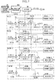
- the first example of the adaptive array antenna transceiver apparatus of the present invention is explained referring to Fig. 1 through Fig. 3 .
- the adaptive array antenna transceiver apparatus comprises a circulator 12 that is an example of a transmitter/receiver common-use device, a radiation pattern control processor 26 corresponding to a radiation pattern control calculation circuit, a signal generator 24 corresponding to a local signal generator, a coupler 15 that is an example of a branching device, and a calibration processor 25 that corresponds to a calibration control circuit.
- the array antenna is structured by N antenna elements 11 (where N is an arbitrary integer) disposed side by side.
- N is an arbitrary integer
- the segments of the branch of the array antenna on which the antenna elements are disposed are represented by numerical values in parenthesis added to the reference numeral of each element.
- each arrow in Fig. 1 represents the direction of the signal. In the case that there is no need to segment the branches of each element, the.parenthesis and the presentation of the numerical value in the parenthesis are omitted.
- the circulator 12 is provided so that transmitters and receivers can use an antenna element 11 in common.
- the coupler 15 is provided in order to split and extract a part of the signal output from the transmitter 13.
- the signal transmitted from each transmitter passes through the coupler 15 and the circulator 12, and is radiated as a wireless signal from the antenna element 11.
- the signal received at antenna element 11 passes through the circulator 12 and the switch 16, and is input into the receiver.
- the switch 21, the frequency converter 22, the switch 23, the signal generator 24, the calibration processor 25, and the direction control processor 26 are provided in addition to the N branch units 10.
- the switches 16, 21, and 23 respectively are formed so as to be electrically controllable, and in this example each connection state is switched by the control of the calibration processor 25.
- the signal generator 24 outputs a signal having a frequency (
- the frequency converter 22 outputs the result of mixing the signal output by the switch 21 and the signal output by the signal generator 24.
- the signal output by the switch 21 is one part of the signal output by the transmitter 13, and thus has a frequency of f1, and the frequency of the signal output by the signal generator 24 is (
- a frequency component having the frequency of f2 can be obtained at the output of the frequency converter 22. This means that the signal having a frequency of f1 output by the transmitter 13 is converted to a signal having a frequency of f2 when passed through the frequency converter 22.
- the reception frequency of the receiver 14 is f2
- the signal output by the frequency converter 22 is input into the receiver 14
- the amplitude and phase of the signal output by the transmitter 13 can be measured at the receiver 14.
- the local signal of the receiver and the local signal of the transmitter can be used to generate a signal having a frequency (
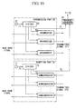
- the signal generator 24 can be realized for example by the circuit shown in Fig. 10 or the circuit shown in Fig. 11 .
- Fig. 10 shows a circuit using a direct conversion method that directly converts the frequency of the baseband and the frequency of the communication frequency band
- Fig. 11 shows a circuit using a superheterodyne method that provides an intermediate frequency and carries out two-stage frequency conversion between the baseband and the transmission frequency band.
- the output signal of the oscillator 61 and the output signal of the oscillator 71 are mixed in the frequency converter 80, and thereby the frequency (
- the frequency of the signal output by the oscillator 65 of the transmitting part 60 is (f1 - fIF)
- the frequency of the signal output by the oscillator 75 of the reception part 70 is (f2 - fIF).
- a frequency (f1 - f2) of the difference therebetween is obtained.
- a signal of (f1 - f2) is generated using the local signals to be used for frequency conversion respectively in the transmitter 13 and the receiver 14, and thus the circuit structure can be simplified because providing a new oscillator is unnecessary. Furthermore, because a deviation between the frequency used in the signal generator 24 and the actual transmission frequency and reception frequency does not occur, the precision of the calibration can be improved.
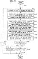
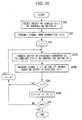
- step S 10 the output of the frequency converter 22 is connected to the switch 16(1) of the reference branch by controlling switch 23.
- step S 11 by controlling the switch 16(1) of the reference branch, the output of switch 23 is connected to the input of the receiver 14(1) of the reference branch.
- step S 13 the switch 21 is switched so that the output of the coupler 15(i) corresponding to the value of the counter i is selected.
- step S 14 the signal from the transmitter 13(i) of the branch corresponding to the value of the counter i is transmitted. Moreover, the signals from the transmitter 13(i) need only be transmitted during measurement.
- step S 15 the ith signal k(i) received by the receiver 14(1) of the reference branch is measured from the output signal of the receiver 14(1).
- This signal K(i) is the value that includes information about the amplitude and phase of the reception signal.
- step 17 In the case that the processing for all of the N branches has finished, the processing advances to step 17 after passing though steps S 18 and S 19, the value of the counter i is incremented, and the processing returns to step S 13.
- K(i) T i ⁇ Q ⁇ R 1
- T(i) amplitude and phase values produced at the transmitter 13(i)
- Q the fluctuating component of the amplitude and phase due to temperature characteristics
- R(1) the amplitude and phase produced by the receiver 14(1).
- the calibration value H(i) obtained by the calibration control procedure in Fig. 2 is a relative value of the amplitude and phase values of the transmitters 13(i) with respect to the reference branch.
- the amplitude and phase values fluctuate due to the influence of the change, for example, in temperature characteristics, the Q component thereof is cancelled out in the above Equation 3, and thus the influence of temperature characteristics does not appear in the calibration value H(i).
- step S 23 switch 23 is controlled, and thereby the output of the frequency converter 22 is connected with the switch 16(i) of the branch depending on the value of the counter i.
- step S 24 the switch 16(i) is controlled, and thereby the output of the frequency converter 22 and the input of the receiver 14(i) of the ith branch are connected.
- step S 25 the signal S(i) received by the receiver 14(i) of the ith branch is measured from the output signal of the receiver 14(i).
- This signal S(i) is the value that includes information about the amplitude and phase of the reception signal.
- the processing advances to step S 27 after passing through steps S 25 and S 26, the value of the counter i is incremented, and the processing returns to step S 23.
- step 27 In the case that the processing for all of the N branches has finished, the processing advances to step 27 after passing though steps S 28 and S29, the value of the counter i is incremented, and the processing returns to step S 23.
- R(i) the amplitude and phase values produced by the receivers 14(i).
- This example is a modification of the first example and the elements and processing in Fig. 4 to Fig. 6 corresponding to those of the first example are shown with the identical reference numerals and step numbers.
- the adaptive array antenna transceiver apparatus comprises a circulator 12 that is an example of a transmitter/receiver common-use device, a radiation pattern control processor 26 corresponding to a radiation pattern control calculation circuit, a coupler 15 and a coupler 32 that are an example of a branching device, and a calibration processor 25B that corresponds to a calibration control circuit.
- each branch unit 10 including that element is formed.
- Each branch unit 30 is formed by an antenna element 11, circulator 12, a transmitting part 31, a receiver 14, a coupler 15, and a switch 16.
- the transmitting part 31 provides a transmitter 35, a coupler 32, and a frequency converter 33.
- the frequency of the signal output by the transmitter 35 is f2, and is identical to the reception frequency of the receiver 14.
- the frequency converter 33 connected to the output of the transmitter 35 converts the frequency of the signal output by the transmitter 35 to f1 and applies this to the circulator 12. Therefore, the transmission frequency f1, and this differs from the reception frequency of the receiver 14.
- f1 > f2 the frequency converter 33 connected to the output of the transmitter 35 converts the frequency of the signal output by the transmitter 35 to f1 and applies this to the circulator 12. Therefore, the transmission frequency f1, and this differs from the reception frequency of the receiver 14.
- f1 > f2 the frequency converter 33 connected to the output of the transmitter 35 converts the frequency of the signal output by the transmitter 35 to f1 and applies this to the circulator 12. Therefore, the transmission frequency f1, and this differs from the reception frequency of the receiver 14.
- f1 > f2 the frequency converter 33 connected to
- the circulator 12 is provided so that transmitters and receivers can use an antenna element 11 in common.
- the coupler 15 is provided in order to split and extract the transmission signal having a frequency of f1 that was frequency converted by the frequency converter 33.
- the coupler 32 is provided for splitting and directly extracting the transmission signal having a frequency f2 output by the transmitter 35 in the transmitting part 31.
- the calibration processor in Fig. 4 executes respectively the calibration control procedure for the transmitter shown in Fig. 5 and the calibration control processing for the receiver shown in Fig. 6 .
- step S 10B in Fig. 5 by controlling the switch 16(1) of the reference branch, the output of the frequency converter 22 is input into the receiver 14(1).
- the signal transmitted from the transmitter 31 of each of the branches can be received at the receiver 14(1) of the reference branch.
- the amplitude and phase values that include the characteristics of the frequency converter 33 included in the transmitting part 31 must be measured.
- the calibration value H(i) obtained by the calibration control procedure in Fig. 5 is a relative value of the amplitude and phase values of the transmitter 31(i) with respect to the reference branch.
- the amplitude and phase values fluctuate due to the influence of this change, for example, in temperature characteristics, the Q component thereof is cancelled out in the above Equation 8, and thus the influence of temperature characteristics does not appear in the calibration value H(i).
- step S 20 is unnecessary and has been omitted.
- step S 23B of Fig. 6 by controlling the switch 38, the output of the coupler 32 provided in the transmitting part 31(1) of the reference branch is connected to the switch 16(i) of the ith branch.
- the signal transmitted from the transmitter 35(1) of the reference branch can be input into the receiver 14(i) of each of the branches.
- the frequency f2 of the output signal of the transmitter 35 is identical to the reception frequency f2 of the receiver 14, and thus each of the receivers 14(i) can receive as-is the signal input from the switch 16.
- the calibration values P(i) obtained by the calibration control procedure in Fig. 6 is a relative value of the amplitude and phase values of the receiver 14(i) with respect to the reference branch. Therefore, when receiving at each of the branches, by multiplying the amplitude and phase values of each of the receivers 14(i) by the calibration values P(i) obtained by the calibration control procedure in Fig. 3 , the error in the amplitude and phase values between each of the branches in the receiver 14 can be compensated.
- the fluctuation component of the amplitude and phase values due to the temperature characteristics in the above Equation 8 in practice include the fluctuation component in the transmitting part 31 of each of the branches, the fluctuation component in the receiver 14, and the fluctuation component in the frequency converter 22 to be used in calibration. Therefore, the characteristics of the frequency converter 22 change with respect to the temperature changes that accompany the passage of time, but because the frequency converter 22 is used on common when measuring the amplitude and phase values of any of the branches during calibration processing, the fluctuation component Q of the amplitude and phase values of the single frequency converter 22 do not influence the calibration values.
- FIG. 7 A third example of the adaptive array antenna transceiver apparatus of the present invention will be explained referring to Fig. 7 to Fig. 9 .
- the adaptive array antenna transceiver apparatus comprises a circulator 12 that is an example of a transmitter/receiver common-use device, a radiation pattern control processor 26 corresponding to a radiation pattern control calculation circuit, a signal generator 24 that corresponds to the local signal generator, a coupler 15 that is an example of a branching device, and a calibration processor 25C that corresponds to a calibration control circuit.
- the array antenna is structured by N antenna elements 11 (where N is an arbitrary integer) disposed side by side.
- the segments of the branch of the array antenna on which the antenna elements are disposed are represented by numerical values in parenthesis added to the reference numeral of each element.
- each arrow in Fig. 7 represents the direction of the signal. In the case that there is no need to segment the branches of each of the antenna elements, the parenthesis and the presentation of the numerical value in the parenthesis are omitted.
- each branch unit 40 including that element is formed.
- Each branch unit 40 is formed by an antenna element 11, circulator 12, a transmitter 13, a receiver 14, a coupler 15, switches 16, 41, 42, and a frequency converter 43
- switches 41 and 42, and the frequency converter 43 for the Nth branch unit 40(N) are unnecessary and therefore omitted.
- the circulator 12 is provided so that transmitters and receivers can use an antenna element 11 in common.
- the coupler 15 is provided in order to split and extract a part of the signal output by the transmitter 13.
- the signals transmitted from each of the transmitters 13 pass through the coupler 15 and the circulator 12 and is radiated as a wireless signal from the antenna element 11.
- the signal received at the antenna element 11 passes through the circulator 12 and the switch 16, and is input into the receiver 14.
- the radiation pattern control processor 26 combines the signals of the N branches in order to carry out adaptive control of the radiation pattern of the array antenna, and at the same time to control the weighting of each of the branches during synthesis.
- the calibration processor 25C carries out calibration by finding separately the amplitude and phase errors of the transmitter 13 and the receiver 14 of each of the branch units 40. In practice, the calibration processor 25C finds the value to be used in calibration of each of the transmitters 13 by implementing the control shown in Fig. 8 , and finds the value to be used in calibration of each of the receivers 14 by implementing the control shown in Fig. 9 .
- the switches 16, 41, and 42 are each formed so as to be electrically controllable, and in this example, the connection condition of each is switched by the control of the calibration processor 25C.
- the frequency converter 43 of each of the branches uses the signal (having a frequency f1 - f2) from the respective dividers 39, and converts the frequency of the signal (having a frequency of f1) output by the switch 41 to f2.
- the switch 42 of the ith branch selectively outputs the signal (having frequency f2) output by the frequency converter 43(i) of the relevant branch to either one of the switch 16(i) of the relevant branch or the switch 16(i +.1) of the adjacent branch.
- the first branch is assigned to serve as the reference branch.
- the switch 16(1) of the reference branch selects either one of the signal output by the switch 24 of the relevant branch or the reception signal from the circulator 12, and applies this to the input of the receiver 14.
- the switches 16(j) of the second to (N - 1) branch respectively select any one of the signal from the switch 42(j -1) of the adjacent branch, the signal from the switch 42(j) of the relevant branch, or the signal from the circulator 12.
- the switch 16(N) of the Nth branch selects either one of the signal from switch 42(N - 1) of the adjacent branch or the signal from the circulator 12, and applies this to the inputs of the receiver 14.
- the signal generator 24 outputs a signal having a frequency (
- the frequency transmitter 43 of each of the branches converts the frequency of the signal output from the transmitter 13 from f1 to f2 using the signal (
- the reception frequency of the receiver 14 is f2
- the signals output by each of the frequency converters 43 are input into the receiver 14, the amplitude and phase of the signal output by the transmitter 13 can be measured.
- the respective combination of two branches determined by being matched with the antenna elements in the order of their arrangement is formed so that the switches 41 and 42 select the path of the signal.
- the combination of two branches selected by the switches 41 and 42 can be determined arbitrarily, without the antenna element 11 having to be identical to the two branches that are actually adjacent.
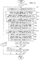
- step S 30 the value of the counter i is initialized.
- step S 31 the value of counter j is assigned the value of the counter i incremented by 1.
- the processing of steps S 31 to S 45 is repeatedly executed depending on the values of the counters i and j.
- the value of the counter i represents the object branch, and the value of the counter j represents the branch adjacent to the object branch.
- step S 32 by controlling the switch 42(i) of the object branch, the output of the frequency converter 43 is connected to the switch 16(j) of the adjacent branch.
- step S 33 by controlling the switch 16(j) of the adjacent branch, the output of the switch 42(i) of the object branch is connected to the input of the receiver 14(j) of the adjacent branch.
- step S 37 the signal from the transmitter 13(i) of the adjacent branch corresponding to the value j of the counter is transmitted. Moreover, transmission of the signal from the transmitter 13(j) needs to be transmitted only during measurement.
- step S 42 the calibration value H2(j) is stored as calibration value H3(j).
- step S 44 the ith calibration value H3(i) found for the previous branch is multiplied by the jth calibration value H2(j) found for the relevant branch (the object branch and the adjacent branch), and the result is stored as the calibration value H3(j).
- the calibration value H3(j) of steps S 42 and S 44 will be explained.
- the calibration value H2(2) H3(2).
- the amplitude and phase values of each of the transmitters 13(j) are multiplied by the calibration values H3(j) obtained by the calibration control procedure in Fig. 8 , and thereby the error in amplitude and phase in the transmitter 13 between the branches can be compensated.
- step S 50 the value of the counter i is initialized.
- step S 51 the value of counter j is assigned the value of the counter i incremented by 1.
- the processing of steps S51 to S 65 is repeatedly executed depending on the values of the counters i and j.
- the value of the counter i represents the object branch
- the value of the counter j represents the branch adjacent to the object branch.
- step S 52 the signal from the transmitter 13 (i) of the object branch, which corresponds to the value of the counter i, is transmitted. Moreover, the signal from the transmitter 13(i) needs to be transmitted only during measurement.
- step S 53 by controlling the switch 41(i) of the object branch, which corresponds to the value of the counter i, the output of the coupler 15(i) is selected.
- step S 54 by controlling the switch 42(i) of the object branch, the output of the frequency converter 43 and the switch 16(i) of the object branch.
- step S 55 by controlling the switch 15(i) of the object branch, the output of the switch 42(i) of the object branch is connected to the output of the receiver 14(j) of the object blanch.
- step S 56 the jth signal S1(j) received by the receiver 14(j) of the object branch is measured from the output signal of the receiver 14(j).
- This signal S1(j) is the value that includes information about the amplitude and phase of the reception signal.
- step S 57 by controlling the switch 42(i) of the object branch, the output of the frequency converter 43 and the switch 16(j) of the adjacent branch are connected.
- step S 58 by controlling the switch 16(j) of the adjacent branch, the output of the switch 43(i) of the object branch is connected to the input of the receiver 14(j) of the adjacent branch
- step S 59 the jth signal S2(j) received by the receiver 14(j) of the adjacent branch is measured from the output signal of the receiver 14(j).
- This signal S2(j) is the value that includes information about the amplitude and phase of the reception signal.
- step S 63 the processing passes through steps 61 and 62 to advance to step S 63, the value of the counter i is incremented, and the processing returns to step S 51.
- step S 65 the processing passes through steps 61 to S 64, and advances to step 65.
- step S 62 the calibration value P2(j) is stored as calibration value P3(j).
- step S 64 the ith calibration value P3(i) found for the previous branch is multiplied by the jth calibration value P2(j) found for the relevant branch (the object branch and the adjacent branch), and the result is stored as the calibration value P3(j).
- the calibration value P3(j) of steps S 62 and S 64 will be explained.
- j 2
- the calibration value P2(2) P3(2).
- the calibration value P3(j) obtained by the calibration control procedure shown in Fig. 9 is a relative value of the amplitude and phase values of the receiver 14(j) with respect to the reference branch.
- the measured amplitude and phase values fluctuate due to the influence of temperature characteristics, etc., with the passage of time, but the Q component thereof is cancelled in the above Equation 21, and thus the influence of the temperature characteristics does not appear in the calibration value P3(j).
- the amplitude and phase values of each of the transmitters 14(j) are multiplied by the calibration values P3(j) obtained by the calibration control procedure in Fig. 9 , and thereby the error in amplitude and phase in the receiver 14 between the branches can be compensated.
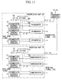
- the fourth example of the adaptive array antenna transceiver apparatus of the present invention will be explained referring to Fig. 12 to Fig. 16 , and Fig. 10 , Fig. 11 , and Fig. 18 .
- Fig. 12 is a block diagram showing the structure of the adaptive array antenna transceiver apparatus of the present embodiment.
- Fig. 13 is a flowchart showing the calibration control procedure of the transmitter of this example.
- Fig. 14 is a flowchart showing the calibration control procedure of the receiver of this embodiment.
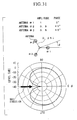
- Fig. 15A is a planar drawing showing an example of the arrangement of the antenna elements and the additional antenna.
- Fig. 16 is a planar drawing showing an example of the arrangement of the antenna elements and the additional antenna.
- Fig. 10 is a block diagram showing an example of a generating circuit (1) having a frequency of f1 - f2.
- Fig. 11 is a block diagram of a generating circuit (2) having a frequency of f1 - f2.
- Fig. 18 is a block diagram showing the amplitude and phase values of each part of the ith branch.
- the array antenna is structured by N antenna elements 111 (where N is an arbitrary integer) disposed side by side.
- the segments of the branch of the array antenna on which the antenna elements are disposed are represented by numerical values in parenthesis added to the reference numeral of each element.
- each arrow in Fig. 12 represents the direction of the signal. In the case that there is no need to segment the branches of each element, the parenthesis and the presentation of the numerical value in the parenthesis are omitted.
- a branch unit 110 including that element is formed. All branch units 110 are formed by identical structures.
- Each of the branches comprises an antenna element 111, switch 112, circulators 11, a transmitting part 115, a receiver 118, a frequency converter 116, switches 117, and a receiver 118.
- the transmitting part 115 provides a transmitter 121, a coupler 122, and a frequency converter 123.
- the coupler 122 is provided for separating and extracting a part of a signal output by the transmitter 121 in the transmitting part 115.
- the circulators 113, 114, and 122 are provided so that a transmitter and a receiver can use an antenna element 11 in common.
- the signal transmitted from each of the transmitting parts 115 passes through the circulator 113, and switch 112, and is radiated as a wireless signal from an antenna element 111.
- the signal received by the antenna element 111 passes through the switch 112, circulator 113, and switch 117, and is input into the receiver 118.
- the frequency of the signal output by the transmitting part 115 that is, the transmission frequency of the array antenna to be used in communication is f1
- the reception frequency of the array antenna and receiver 118 to be used for communication is f2
- the transmission frequency f1 and the reception frequency f2 are different.
- the frequency of the signal transmitted by the transmitter 121 becomes f2 as the reception frequency of the receiver 118.
- the signal transmitted by the transmitter 121 passes through the frequency converter 123 and is converted to the transmission frequency f1.
- the coupler 122 extracts a signal having a frequency f2 from the output of the transmitter 121.
- the frequency converter 116 inputs the signal having a frequency f1 from the circulator 114, and is converted to a frequency of a signal such that a signal having a frequency of f2 is output.
- a calibration processor 124 In the adaptive array antenna transceiver apparatus in Fig. 12 , a calibration processor 124, a radiation pattern control processor 125, a signal generator 126, a divider 127, an additional antenna 128, and a switch 129 are provided in addition to the N branch units 110.
- the radiation pattern control processor 125 combines the signals of the N branches in order to carry out adaptive control of the radiation pattern of the array antenna, and at the same time, control the weighting of each of the branches during synthesis.
- the calibration processor 124 carries out calibration by finding separately the amplitude and phase error of the transmitter (transmitting part 115 and the antenna element 111) of each of the branch units 110 and the reception system (receiver 118 and antenna element 111).
- the calibration processor finds the value to be used for calibrating the transmission system of each of the branches by implementing the control shown in Fig. 13 , and finds the value to be used for calibrating the reception system of each of the branches by implementing the control shown in Fig. 14 .
- the respective switches 112, 117, and 129 are formed to as to be electrically controllable, and in this example, the various connection states are switched by the control of the calibration processor 124.
- the switch 129 connects the additional antenna 128 to any one of the switches 112 of the N branch units 110.
- the switches 112 of each of the branches connect any one of the antenna elements 111 and switches 129 to any one of the circulators 113 and 114.
- the switch 117 of each of the branches connects either one of the outputs of the circulator 113 or the frequency converter 116 to the input of the receiver 118.
- the signal generator 126 outputs a signal having frequency (
- the signal output by the signal generator is applies to the frequency converters 116 and 123 of each of the branches via the divider 127.
- the frequency converters 116 and 123 carry out conversion of the frequency using the signal from the signal generator 126.
- G ⁇ 1 j T i ⁇ M i , f ⁇ 1 ⁇ L ⁇ 1 k ⁇ M ⁇ 2 f ⁇ 1 ⁇ Q k ⁇ R k
- G ⁇ 2 j T j ⁇ M j , f ⁇ 1 ⁇ L ⁇ 2 k ⁇ M ⁇ 2 f ⁇ 1 ⁇ Q k ⁇ R k
- the amplitude and phase values for the entire transmission system of the ith branch which combines the component T(i) of the amplitude and phase related to f1 of the transmitting part 115 and the component M(i, ft) of the amplitude and phase values related to f1 of the antenna elements 111(j) can be found for each of the branches as a ratio with the other branches.
- the values of the counters i and j must be determined such that the distances between the antenna element 111 of each of the branches and the additional antenna 128 are equal.
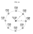
- the antenna elements are disposed in a circle and the additional antenna 128 is disposed at the center thereof, there is no particular problem because the distance between the antenna element 111 of any of the branches and the additional antenna 128 are equal.
- step 134 for the branch corresponding to the value of the counter i, by controlling the switch 112(i), the antenna element 111(i) and the circulator 113(i) are connected.
- step 135 for the branch corresponding to the value of the counter i, by controlling switch 117(i), the circulator 113(i) and the receiver 118 are connected.
- the signal receiver by the antenna element 111(i) passes through the switch 112(i), the circulator 113(i), and the switch 117(i), and is input into the receiver 118(i). Then, in step S 136, the signal (amplitude and phase values) S1(j) of the branch selected from the receiver output of the receiver 118(i) is measured.
- the signal received by the antenna element 111(j) passes through the switch 112(j), the circulator 113(j), and the switch 117(j), and is input into the receiver 118(j). Then, in step 139, the signal (amplitude and phase values) S2(j) of the branch selected from the received output of the receiver 118(j) is measured.
- step S 142 the calibration value P2(j) is stored as calibration value P3(j).
- the calibration value P3(j) is found separately for the respective second to N branches.
- the calibration value P3(j) of the first branch is 1.
- amplitude and phase values S1(j) and S2(j) measured in steps S 136 and S 139 in Fig. 14 are represented by the following equations:
- S ⁇ 1 j T k ⁇ M ⁇ 2 f ⁇ 2 ⁇ L ⁇ 1 k ⁇ M i , f ⁇ 2 ⁇ R i
- S ⁇ 2 j T k ⁇ M ⁇ 2 f ⁇ 2 ⁇ L ⁇ 2 k ⁇ M j , f ⁇ 2 ⁇ R j
- the transmission losses L1(k) and L2(k) are identical.
- the additional antenna 128 and the branch corresponding to the counter k are used in common between the two branches corresponding to the counters i and j, these components are identical.
- the calibration value P3(j) obtained by the calibration control procedure in Fig. 14 is the relative value of the amplitude and phase values of the reception system (receiver 118(j) and antenna element 111(j)) of the jth branch with respect to the reference branch.
- Fig. 17 is a block diagram showing the structure of the adaptive array antenna transceiver apparatus of this embodiment.
- This embodiment is an example of a modification of the fourth example.
- Fig 17 the elements corresponding to those in Fig 12 are indicated with the same reference numbers. The explanations of the elements that are identical to those in the fourth example are omitted.
- the adaptive array antenna transceiver apparatus in this embodiment comprises a radiation pattern control processor corresponding to the direction control computing circuit 125, a coupler 122, which is an example of a branching device, a coupler 131, a circulator 113, which is an example of a transmitter/receiver common-use device, the circulator 114, and a calibration processor 124 corresponding to a calibration control circuit.
- the calibration of the transmitter and receiver which are easily influenced due to temperature fluctuations, is preferably carrier out at short time intervals.
- the switch 134 outputs a signal that has been split by the coupler 122(1) with respect to any one of the switches 117 of the N branch units 110.
- the switch 117 of each of the branches selectively applies any one of the reception signal from the circulator 113, the output signal of the frequency converter 116, or the output of the switch 134 to the input of the receiver 118.
- the selection conditions for each switch 132, 133, 134, and 117 are switched by control of the calibration processor 124.
- the calibration processor 124 implements the following control for calibration, in addition to that explained in Fig. 13 and Fig. 14 .
- the signal having the frequency f2 output from the transmitter 121(i) passes through the coupler 122(i), is converted to the frequency f1 by the frequency converter 123(i), separated by the coupler 131(i), and input into the switch 133.
- this signal passes through the switch 133 and the switch 132, is converted to frequency f2 by the frequency converter 116(1), passes through the switch 117(1), and input into the receiver 118(1). Therefore, the signal output from the transmitting part 115 (transmitter 121, frequency converter 123) of each of the branches is measured at the receiver 118(1) of the reference branch.
- Fig. 19 is a block diagram showing the structure of the adaptive array antenna transceiver apparatus of this example.
- Fig. 20 is a flowchart showing the calibration control procedure of the transmitter of this example.
- the array antenna is structured by N antenna elements 111 (where N is an arbitrary integer) disposed in a line.
- Each of the branch units 110 provides antenna elements 111, a circulator 113, a transmitting part 115, and a receiver 118.
- the coupler 122 and the switch 117 are provided only on the one branch unit 110(1).
- the other branch units 110 have structures that are identical to each other.
- the coupler 122 of the branch unit 110(1) is provided in order to separate and extract a part of the signal output from the transmitting part 115.
- the switch 117 of the branch unit 110(1) is provided in order to switch the signals input into the receiver 118(1).
- the selection state of the switch 117 is electrically controlled by the calibration processor 124.
- the circulator is provided so that the transmitter and receiver can use antenna elements 111 in common.
- the frequency of the signal output by the transmitting part 115 that is, the transmission frequency of the array antenna to be used for communication
- the reception frequency of the array antenna and receiver 118 to be used in communication is f2
- the transmission frequency f1 and the reception frequency f2 are different.
- a transmitter (121) that transmits a signal having a frequency the same as the reception frequency f2 of the receiver 118 and the frequency converter (123) are provided in the transmitting part 115.
- the circulator 143 inputs a signal having a frequency of f1 from the additional antenna 128, and outputs a signal having frequency f2 to the additional antenna 128.
- the radiation pattern control processor 125 combines the signals of N branches and controls the weighting of each of the branches during synthesis.
- a part of the signal (having frequency f1) transmitted by the transmitting part 115 is separated by the coupler 122, and applied to the input of the frequency converter 141.
- the frequency converter 141 executes conversion of the frequency by using the signal (having a frequency of
- the frequency converter 141 mixes the signal input from the coupler 122 and the signal input from the signal generator 126, and carries out conversion of the frequency.
- the frequency of the signal input from the coupler 122 is f1 and the signal input from the signal generator 126 is
- the signal output by the frequency converter 141 passes through the circulator 143 and is radiated as an electro-magnetic wave from the additional antenna 128.
- this signal is input into the frequency converter 142 via the circulator 143.
- the frequency generator executes the conversion of the frequency by using the signal (having a frequency of
- the signal having a frequency of f1 received by the additional antenna 128 is converted to a signal having a frequency of f2 and output from the frequency converter 142.
- the signal output by the frequency converter 142 can be input into the receiver 118(1).
- the frequency of the signal output by the transmitting part 115 is f1
- the frequency received by the receiver 118 is f2
- the signal output by the transmitting part 115 cannot be received as-is by the receiver 118.
- the signal transmitted from the transmitting part 115 can be received by the receiver 118.
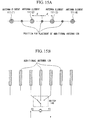
- the position at which the additional antenna 128 is disposed must be determined depending on the positions of the N antenna elements 111 that form the array antenna. As shown in Fig. 15A , in the case that the array elements 111 are arranged spaced at equal intervals on one straight line, the additional antenna must be disposed at the middle position between, for example, two antenna elements 111, such that the distances d between each of these antenna elements 111 and the additional antenna 128 are equal.
- Fig. 15A in the case that a plurality of additional antennas 128 are used, as shown in Fig. 15B , one of the plurality of additional antennas 128 is selectively connected to a circulator using the switch 149.
- the additional antenna 128 can be disposed at the center position of the circle. In this case, the distances d between the antenna elements 111 and the additional antenna 128 are equal for any of the branches.
- the additional antennas 128 are disposed in this manner, the transmission losses between each of the antenna elements 111 and the additional antenna 128 are equal, and a calibration value that is not influenced thereby can be found.
- the calibration control procedure shown in Fig. 20 will be explained.
- the first branch unit 110(1) is assigned to serve as the reference branch, but another branch can serve as the reference. That is, the coupler 122 and the switch 117 can be provided on any one of the branch units 110.
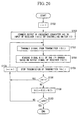
- step S 150 the value of the counter i is initialized.
- the value of the counter i corresponds to the one branch that is the object of calibration.
- step S 152 by controlling switch 117, the output of the frequency converter 142 is connected to the input of the receiver 118(1) of the reference branch.
- steps S 153 to S 160 that follow are repeatedly executed depending on the value of the counter i.
- step S 153 the signal (having a frequency f1) is transmitted from the ith transmitting part 115(j).
- the signal output by the transmitting part 115(i) passes through the circulator 113(i) and is transmitted as a wireless signal from the antenna element 111(i).
- This wireless signal is received by the additional antenna 128.
- the signal received by the additional antenna 128 passes through the circulator 142, and is input into the receiver 118(1).
- step 154 the signal K(i) received by the receiver 118(i) is measured. After the measurement has completed, in the next step S 155, the transmission of the transmitting part 115(i) is stopped.
- the signals output from the transmitting parts 115 included in the respective N branches pass through the path through the antennas (111 and 128) of each of the branches, are respectively received by the receiver 118(1), and the signals K(l) to K(N) are measured.
- the counter i is 1, and thus the processing proceeds from S 156 to S 158. Moreover, the signal K(1) first obtained is saved as the signal of the reference branch.
- the calibration values H(i) are found separately as relative values for each of the second to Nth respective branches.
- the calibration value H(i) of the first branch is 1.
- K i T i ⁇ M i , f ⁇ 1 ⁇ L i ⁇ M a , f ⁇ 1 ⁇ Q ⁇ 2 ⁇ R 1
- the amplitude and phase values of the entire transmission system of the ith branch which are a combination of the component T(i) of the amplitude and phase of related to the f1 of the transmitting part 115(i) and the component M(i, f1) of the amplitude and phase related to f1 of the antenna element 111(i), can be found for each of the branches as a ratio with the other branches.
- the measured amplitude and phase values fluctuate due to the influence of fluctuations in the temperature characteristics, etc., with the passage of time, but the component Q2 thereof is cancelled out in the Equation 124 above, and thus the influence of the temperature characteristics do not appear in the calibration value H(i).
- the calibration value of each of the branches can be found as a relative value with respect to the reference branch.
- the calibration control procedure shown in Fig. 21 will be explained.
- the first branch unit 110(1) is assigned to serve as the reference branch, but another branch can be used as the reference.
- step S 172 the signal from the transmitting part 115(1) of the reference branch is transmitted.
- the signal output from the transmitting part 115(1) is separated by the coupler 122, and after the signal having a frequency of f2 is converted by the frequency converter 141, it passes through the circulator 143, and is transmitted from the additional antenna 128 as a wireless signal.
- the wireless signal transmitted from the additional antenna 128 can be received by the antenna element 111 of each of the branches.
- the frequency of the signal transmitted from the additional antenna 128 is converted to f2, and thus the signal received by the antenna elements 11 can be input and detected directly at the receiver 118.
- steps S 173 to S 178 is repeatedly executed depending on the value of the counter i. Each time these processes are executed, in step S 176, the value of the counter i is updated.
- step S 173 the signal (amplitude and phase values) S(i) of the branch can be measured from the received output of the receiver 118(i) of the ith branch.
- the counter i is 1, and thus the processing proceeds from S 174 to S 176. Moreover, the signal S(1) first obtained is saved as the signal of the reference branch.
- the calibration values P(i) are found separately for each of the second to Nth respective branches.
- the calibration value P(i) of the first branch is 1.
- the amplitude and phase values of the entire reception system of the ith branch which are a combination of the component R(i) of the amplitude and phase of reception part 118(i) and the component M(i, f2) of the amplitude and phase related to f2 of the antenna element 111(i), can be found for each of the branches as a ratio with respect to the reference branch.
- the fluctuation component Q1 of the amplitude and phase values due to temperature characteristics in the Equation 126 above in practice includes the fluctuation component in the transmitting part 115 of each of the branches, the fluctuation component in the receiver 118, and the fluctuation components in the frequency converter 141 used in calibration.
- the characteristics of the frequency converter 141 change with respect to the temperature fluctuations that accompany the passage of time, but because a frequency converter 141 is used in common when measuring the amplitude and phase values of any branch in the calibration processing, the fluctuation component Q1 of the amplitude and phase values of a single frequency component 141 does not influence the found calibration value.
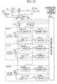
- the seventh example of the adaptive array antenna transceiver apparatus of the present invention will be explained referring to Fig. 22 to Fig. 24 .
- Fig. 22 is a block diagram showing a structure of the adaptive array antenna transceiver apparatus of this example.
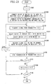
- Fig. 23 is a flowchart showing the calibration control procedure for the transmitter of this embodiment.
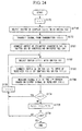
- Fig. 24 is a flowchart showing the calibration control procedure for the receiver of this example
- the adaptive array antenna transceiver apparatus of this example includes a coupler 122, which is an example of a branching device.
- the part of the antenna and current supply are influenced by rapid environmental fluctuations such as temperature with comparative difficulty.
- the high frequency circuits such as transmitters, receivers, electrical amplifiers, and frequency converters are comparatively easily influenced by temperature fluctuations in the electrical amplifier and the circulators, for example.
- the calibrations related to the antenna and power supply be carried out at a comparatively infrequent interval, but the calibration of the high frequency circuits such as transceivers must be carried out at comparatively short time intervals.
- the antenna is structured such that calibration can be implemented for separate transceivers independently.
- calibrations that include the antenna can be realized by the same processing as that used in the sixth example, and the explanation thereof will be omitted.
- switches 151, 152, 153, and 154 are added.
- the switches 151, 152, 153, and 154 are all structured so as to be electrically controllable, and are connected such that their state can be changed by the control of the calibration processor 124.
- the calibration values H2(i) are found separately as relative values for the respective second to Nth branches.
- the calibration value H2(i) of the first branch is 1.
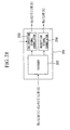
- a switch 21, a frequency converter 22, switch 23, signal generator 24, a calibration/reception signal separator 201, a calibration processor 25, and a radiation pattern control processor 26 are provided in addition to the N branch units 40.
- a part of the calibration processor 25 in the adaptive array antenna transceiver apparatus in Fig. 27 has connections, etc., that differ from those of the calibration processor 25 shown in Fig. 1 .
- the calibration processor in the present example inputs the signal from the switch 23 separated by the calibration/reception signal separator 201 by controlling the connection state of the switches 21 and 23, and finds the calibration value for each of the branches of the array antenna.
- The-divider 202 separates the signal from the receiver 14 designated by the calibration processor, and inputs it into the calibration signal correlator 203 and the reception signal correlator 204.
- the calibration value H(i) obtained by the calibration control in Fig. 29 is a relative value of the amplitude and phase values of the transmitters 13(i) with respect to the reference branch.
- the measured amplitude and phase values fluctuate due to the influence of the change in temperature characteristics over time, but the component Q thereof is cancelled in Equation 204, and thus the influence of the temperature characteristics do not appear in the calibration values H(i).
- step S 20 by controlling the switch S 21, the output of the coupler 15(1) of the reference branch is selected.
- step S 25D the ith signal S'(i) received by the receiver 14(i) of the reference branch is measured from the output signal of the calibration signal correlator 203 in the calibration/reception signal separator 201.
- the signal S'(i) is a value that includes the amplitude and phase information of the reception signal. Because the first time the value of the counter i is 1, passing from step S 25 to S 26, the processing advances to step S 27, the value of the counter i is incremented, and the processing returns to step S 23.
- step S 28 In the case that the processing for all N branches has finished, the processing passes from step S 28 to S 29, advances to step S 27, increments the value of the counter i, and returns to step S 23.
- the calibration values S'(i) are found separately for the respective second to Nth branches.
- the calibration value P(1) of the first branch is 1.
- the fluctuation component Q of the amplitude and phase values due to temperature characteristics in Equation 202 and Equation 206 include in practice the fluctuation component in the transmitter 13 of each of the branches, the fluctuation component in the receiver 14, and the fluctuation component in the frequency converter 22 to be used in calibration. Therefore, the characteristics of the frequency converter 22 change with respect to temperature changes that accompany the passage of time, but because the frequency converter 22 is used in common when measuring the amplitude and phase values of any of the branches in the calibration processing, the fluctuation component Q of the amplitude and phase values of the single frequency converter 22 does not influence the calibration values.
- the amplitude and phase values of the transmitter and receiver between each of the branches can be calibrated separately, and the error in amplitude and phase between each of the branches produced by environmental fluctuations due to differences in the setting positions and changes in the temperature characteristics of the base stations can be compensated.
- the calibration of the amplitude and phase values of the transmitting part 115 and reception part between each of the branches can be carried out separately, including even the antenna.
- the error in the amplitude and phase between each of the branches produced by environmental fluctuation because of differences in the setting positions of the base stations and changes in the temperature characteristics during communication can be compensated.
Landscapes
- Engineering & Computer Science (AREA)
- Computer Networks & Wireless Communication (AREA)
- Signal Processing (AREA)
- Physics & Mathematics (AREA)
- Electromagnetism (AREA)
- Variable-Direction Aerials And Aerial Arrays (AREA)
- Radio Transmission System (AREA)
Claims (6)
- Adaptive Gruppenantenne-Sende-/Empfangsvorrichtung, umfassend N Antennenelemente (111), wobei N eine ganze Zahl ist und Drei oder mehr bezeichnet; N Transmitter (121) und Empfänger (118); eine gemeinsam genutzte Vorrichtung (113), die die Transmitter (121) und Empfänger (118) mit jedem der Antennenelemente (111) verbindet; dadurch gekennzeichnet, dass sie ferner einen Strahlungsmuster-Steuerprozessor (125) umfaßt, der das Strahlungsmuster der Gruppenantenne durch Synthetisieren des Ausgangssignals der Mehrzahl von Empfängern durch Wichtung der Amplitude und Phase hinsichtlich eines Signals steuert, das von jedem der entsprechenden Antennenelemente (111) in die Mehrzahl von Empfängern eingegeben wurde, und gleichzeitig die Empfiartgsfrequenz der Gruppenantenne, die für die Kommunikation verwendet werden soll, und die Übertragungsfrequenz verschieden sind, und:einen Lokalsignalgenerator (126), der ein Signal ausgibt, das eine Frequenz aufweist, die der Differenz zwischen der Empfangsfrequenz f2 der Empfänger und der Übertragungsfrequenz f1 der Transmitter entspricht;N Transmitter (121), für die die Frequenz des übertragenen Signals identisch zur Empfangsfrequenz der Gruppenantenne ist;einen ersten Frequenzwandler (123), der die Frequenz von Signalen, die von jedem der N Transmitter übertragen wurden, in die übertragene Frequenz der Gruppenantenne wandelt;N Teilungsvorrichtungen (112), die vor der Wandlung durch den ersten Frequenzwandler ein Signal aus dem Ausgangssignal jedes der N Transmitter extrahieren;N Empfänger (118), für die die Frequenz des Empfangssignals identisch zur Empfangsfrequenz der Gruppenantenne ist;einen zweiten Frequenzwandler (116), der ein Signal, das eine Frequenz aufweist, die identisch zur übertragenen Frequenz der Gruppenantenne ist, in eine Frequenz wandelt, die identisch zur Empfangsfrequenz der Gruppenantenne ist;N erste gemeinsam genutzte Vorrichtungen (113), die zwischen dem Ausgang des ersten Frequenzwandlers, dem Eingang des Empfängers und jedem der Antennenelemente vorgesehen sind;N zweite gemeinsam genutzte Vorrichtungen (114), die zwischen dem Ausgang der Teilungsvorrichtung, dem Eingang des zweiten Frequenzwandlers und jedem der Antennenelemente vorgesehen sind;zumindest eine zusätzliche Antenne (128), die mit einem beliebigen der N Transmitter oder N Empfänger verbunden sein kann;einen ersten Schalter (112), der auf jedem Antennenelement vorgesehen ist und entweder eines der Antennenelemente oder die zusätzliche Antenne entweder mit der ersten gemeinsam genutzten Vorrichtung oder der zweiten gemeinsam genutzten Vorrichtung verbindet;einen zweiten Schalter (117), der auf jedem Empfänger vorgesehen und mit dem Eingang der Empfänger verbunden ist und entweder die Empfangssignale von der ersten gemeinsam genutzten Vorrichtung oder die Empfangssignale, die vom zweiten Frequenzwandler ausgegeben wurden, selektiv eingibt;einen dritten Schalter (129), der die zusätzliche Antenne mit einem beliebigen der ersten Schalter verbindet; undeine Kalibrierungs-Steuerschaltung (124), die den ersten Schalter, den zweiten Schalter und den dritten Schalter steuert und gleichzeitig den Kalibrierungswert der Amplitude und Phase zwischen Zweigen der Gruppenantenne basierend auf den Amplituden- und Phasenwerten ermittelt, die von jedem der Empfänger erhalten wurden.
- Adaptive Gruppenantenne-Sende-/Empfangsvorrichtung nach Anspruch 1, wobei die Kalibrierungs-Steuerschaltung (124):den ersten Schalter, den zweiten Schalter und den dritten Schalter steuert und aus den N Transmittern den ersten Transmitter oder den zweiten Transmitter selektiert, die jeweils in Zweigen der zwei Antennenelemente enthalten sind, die gleiche Abstände zur zusätzlichen Antenne aufweise, und gleichzeitig aus den N Empfängern einen Kalibrierungsempfänger selektiert, der in einem Zweig enthalten ist, der von dem des ersten Transmitters und des zweiten Transmitters verschieden ist, den dritten Schalter mit einem Kalibrierungsempfänger verbindet, der in einem Zweig enthalten ist, der von dem des ersten Transmitters und des zweiten Transmitters verschieden ist;das Signal, welches das Signal ist, das vom ersten Transmitter ausgegeben und vom ersten Frequenzwandler frequenzgewandelt wurde, vom Antennenelement des Zweigs ausgibt, der im ersten Transmitter enthalten ist;das Ausgangssignal, welches das Signal vom ersten Transmitter ist, das durch die zusätzliche Antenne empfangen und vom zweiten Frequenzwandler frequenzgewandelt wurde, in den Kalibrierungsempfänger eingibt und einen ersten gemessenen Wert detektiert, der am Kalibrierungsempfänger erhalten wurde;das Signal, welches das Signal ist, das vom zweiten Transmitter ausgegeben und vom ersten Frequenzwandler frequenzgewandelt wurde, vom Antennenelement überträgt, das im zweiten Transmitter enthalten ist;das Ausgangssignal, welches das Signal vom zweiten Transmitter ist und von der zusätzlichen Antenne empfangen und durch den zweiten Frequenzwandler frequenzgewandelt wurde, in den Kalibrierungsempfänger eingibt und den zweiten gemessenen Wert detektiert, der am Kalibrierungsempfänger erhalten wurde;das Verhältnis des zweiten gemessenen Wertes und des ersten gemessenen Wertes berechnet, das als erster Kalibrierungswert dienen soll;den ersten Kalibrierungswert für die jeweilige Mehrzahl von Zweigen basierend auf dem ersten gemessenen Wert und dem zweiten gemessenen Wert ermittelt, die gemessen wurden, indem die Selektion des ersten Transmitter und des zweiten Transmitter jeweils in Folge geschaltet wurden; undden ersten Kalibrierungswert des relevanten Zweigs unter Verwendung des ersten Kalibrierungswerts, der an den anderen Zweigen erhalten wurde, für andere Zweige als den im voraus zugeordneten Referenzzweig kalibriert und den ersten Kalibrierungswert im Hinblick auf den ersten Referenzzweig als relativen Wert berechnet.
- Adaptive Gruppenantenne-Sende-/Empfangsvorrichtung nach Anspruch 1, wobei die Kalibrierungs-Steuerschaltung (124):den ersten Schalter, den zweiten Schalter und den dritten Schalter steuert und aus den N Transmittern den ersten Transmitter oder den zweiten Transmitter selektiert, die jeweils in Zweigen von zwei Antennenelementen enthalten sind, die gleiche Abstände zur zusätzlichen Antenne aufweisen, und gleichzeitig aus den N Transmittern einen Kalibrierungstransmitter selektiert, der in einem Zweig enthalten ist, der von dem des ersten Empfängers und des zweiten Empfängers verschieden ist;das Signal, das vom Kalibrierungstransmitter ausgegeben wurde, von der zusätzlichen Antenne über die Teilungsvorrichtung, die zweite gemeinsam genutzte Vorrichtung, den ersten Schalter und den dritten Schalter überträgt;das Signal vom Kalibrierungstransmitter, das vom Antennenelement der Zweige empfangen wurde, die im ersten Empfänger enthalten sind, in den ersten Empfänger eingibt und den ersten gemessenen Wert detektiert, der am ersten Empfänger erhalten wurde;das Signal vom Kalibrierungstransmitter, das vom Antennenelement des Zweiges empfangen wurde, der im zweiten Empfänger enthalten ist, in den zweiten Empfängers eingibt und einen zweiten gemessenen Wert detektiert, der am zweiten Empfängers erhalten wurde;das Verhältnis des zweiten Meßwertes und des ersten Meßwertes als einen ersten Kalibrierungswert berechnet;die ersten Kalibrierungswerte der jeweiligen Mehrzahl von Zweigen basierend auf dem ersten gemessenen Wert und dem zweiten gemessenen Wert ermittelt, die jeweils durch In-Folge-Schalten der Selektion des ersten Empfängers und des zweiten Empfängers gemessen wurden; undden ersten Kalibrierungswert des relevanten Zweiges unter Verwendung des ersten Kalibrierungswertes kalibriert, der an den anderen Zweigen erhalten wurde, und den ersten Kalibrierungswert als relativen Wert im Hinblick auf den Referenzzweig berechnen.
- Adaptive Gruppenantenne-Sende-/Empfangsvorrichtung nach Anspruch 1, wobei die N Antennenelemente (111) in einem gleichen Abstand auf einer geraden Linie angeordnet sind und gleichzeitig die zusätzliche Antenne (128) an einer Position in der Mitte zweier Antennenelemente angeordnet ist.
- Adaptive Gruppenantenne-Sende-/Empfangsvorrichtung nach Anspruch 1, wobei N Antennenelemente (111) in gleichen Abständen auf einem Kreis angeordnet sind und gleichzeitig die zusätzliche Antenne (128) an der Zentrumsposition des Kreises angeordnet ist.
- Adaptive Gruppenantenne-Sende-/Empfangsvorrichtung nach Anspruch 1, wobei:ein Kombinator, der das empfangene Signal von der ersten gemeinsam genutzten Vorrichtung und das empfangene Signal, das vom zweiten Frequenzwandler ausgegeben wurde, kombiniert und dieses Signal an den Empfänger ausgibt, anstelle des zweiten Schalters vorgesehen ist;ferner eine Kalibrierungs-/Empfangssignal-Trennungsschaltung vorgesehen ist, die das Empfangssignal von der ersten gemeinsam genutzten Vorrichtung und das empfangene Signal, das vom zweiten Frequenzwandler ausgegeben wurde, trennt/ausgibt; und wobeidie Kalibrierungs-Steuerschaltung (124) den Verbindungszustand des ersten Schalters steuert, das empfangene Signal eingibt, das vom zweiten Frequenzwandler ausgegeben und von der Kalibrierungs-/Empfangssignal-Trennungsschaltung getrennt wurde, und den Kalibrierungswert jedes der Zweige der Gruppenantenne ermittelt.
Applications Claiming Priority (5)
| Application Number | Priority Date | Filing Date | Title |
|---|---|---|---|
| JP35599599 | 1999-12-15 | ||
| JP36535299 | 1999-12-22 | ||
| JP2000113316 | 2000-04-14 | ||
| EP00403526A EP1120858B1 (de) | 1999-12-15 | 2000-12-14 | Sendeempfänger mit adaptiver Gruppenantenne |
| EP07100740A EP1777838B1 (de) | 1999-12-15 | 2000-12-14 | Adaptive Gruppenantennen-Sende/Empfangsvorrichtung |
Related Parent Applications (3)
| Application Number | Title | Priority Date | Filing Date |
|---|---|---|---|
| EP00403526.7 Division | 2000-12-14 | ||
| EP07100740A Division EP1777838B1 (de) | 1999-12-15 | 2000-12-14 | Adaptive Gruppenantennen-Sende/Empfangsvorrichtung |
| EP07100740.5 Division | 2007-01-18 |
Publications (3)
| Publication Number | Publication Date |
|---|---|
| EP2139071A2 EP2139071A2 (de) | 2009-12-30 |
| EP2139071A3 EP2139071A3 (de) | 2010-03-03 |
| EP2139071B1 true EP2139071B1 (de) | 2011-04-13 |
Family
ID=27341529
Family Applications (6)
| Application Number | Title | Priority Date | Filing Date |
|---|---|---|---|
| EP07100740A Expired - Lifetime EP1777838B1 (de) | 1999-12-15 | 2000-12-14 | Adaptive Gruppenantennen-Sende/Empfangsvorrichtung |
| EP09172379A Expired - Lifetime EP2139071B1 (de) | 1999-12-15 | 2000-12-14 | Adaptive Gruppenantenne-Sende/Empfangsvorrichtung |
| EP09172376A Expired - Lifetime EP2139069B1 (de) | 1999-12-15 | 2000-12-14 | Adaptive Gruppenantenne-Sende-Empfangsvorrichtung |
| EP09172373A Expired - Lifetime EP2139068B1 (de) | 1999-12-15 | 2000-12-14 | Adaptive Gruppenantenne-Sende-Empfangsvorrichtung |
| EP00403526A Expired - Lifetime EP1120858B1 (de) | 1999-12-15 | 2000-12-14 | Sendeempfänger mit adaptiver Gruppenantenne |
| EP09172377A Expired - Lifetime EP2139070B1 (de) | 1999-12-15 | 2000-12-14 | Adaptive Gruppenantenne-Sende/Empfangsvorrichtung |
Family Applications Before (1)
| Application Number | Title | Priority Date | Filing Date |
|---|---|---|---|
| EP07100740A Expired - Lifetime EP1777838B1 (de) | 1999-12-15 | 2000-12-14 | Adaptive Gruppenantennen-Sende/Empfangsvorrichtung |
Family Applications After (4)
| Application Number | Title | Priority Date | Filing Date |
|---|---|---|---|
| EP09172376A Expired - Lifetime EP2139069B1 (de) | 1999-12-15 | 2000-12-14 | Adaptive Gruppenantenne-Sende-Empfangsvorrichtung |
| EP09172373A Expired - Lifetime EP2139068B1 (de) | 1999-12-15 | 2000-12-14 | Adaptive Gruppenantenne-Sende-Empfangsvorrichtung |
| EP00403526A Expired - Lifetime EP1120858B1 (de) | 1999-12-15 | 2000-12-14 | Sendeempfänger mit adaptiver Gruppenantenne |
| EP09172377A Expired - Lifetime EP2139070B1 (de) | 1999-12-15 | 2000-12-14 | Adaptive Gruppenantenne-Sende/Empfangsvorrichtung |
Country Status (5)
| Country | Link |
|---|---|
| US (1) | US6690952B2 (de) |
| EP (6) | EP1777838B1 (de) |
| KR (1) | KR100382454B1 (de) |
| CN (1) | CN1218589C (de) |
| DE (6) | DE60045853D1 (de) |
Families Citing this family (107)
| Publication number | Priority date | Publication date | Assignee | Title |
|---|---|---|---|---|
| JP2001111464A (ja) * | 1999-10-08 | 2001-04-20 | Matsushita Electric Ind Co Ltd | 基地局装置及び無線送信方法 |
| JP3597101B2 (ja) * | 2000-02-21 | 2004-12-02 | 埼玉日本電気株式会社 | 受信回路及びアダプティブアレイアンテナシステム |
| JP2001245268A (ja) * | 2000-02-29 | 2001-09-07 | Toshiba Corp | コンテンツ伝送システム及びコンテンツ処理装置 |
| US20020118783A1 (en) * | 2001-02-26 | 2002-08-29 | Peter Cripps | Smart antenna based spectrum multiplexing using a pilot signal |
| US7158501B2 (en) * | 2001-05-29 | 2007-01-02 | Kabushiki Kaisha Toshiba | Wireless communication apparatus |
| CN1545770B (zh) * | 2001-05-31 | 2013-03-06 | 马格诺利亚宽带股份有限公司 | 通信方法和设备以及用于改进通信设备的系统性能的方法 |
| US8249187B2 (en) * | 2002-05-09 | 2012-08-21 | Google Inc. | System, method and apparatus for mobile transmit diversity using symmetric phase difference |
| US20050116876A1 (en) * | 2001-08-14 | 2005-06-02 | Calin Moldoveanu | Distribution system for antenna array |
| US7142830B2 (en) * | 2001-09-19 | 2006-11-28 | Nokia Corporation | Adaptive transceiver system |
| EP1428328A1 (de) * | 2001-09-19 | 2004-06-16 | Nokia Corporation | Adaptives sender-empfängersystem |
| US20040266483A1 (en) * | 2001-10-05 | 2004-12-30 | Seung-Won Choi | Calibration apparatus for smart antenna and method thereof |
| US20060019712A1 (en) * | 2001-11-14 | 2006-01-26 | Seung-Won Choi | Calibration apparatus for smart antenna and method thereof |
| US7031669B2 (en) * | 2002-09-10 | 2006-04-18 | Cognio, Inc. | Techniques for correcting for phase and amplitude offsets in a MIMO radio device |
| FR2848302B1 (fr) * | 2002-12-10 | 2005-05-27 | Thales Sa | Procede de calibration d'une source hyperfrequence |
| FR2849970A1 (fr) * | 2003-01-10 | 2004-07-16 | Thomson Licensing Sa | Systeme de mesure de qualite de reception en diversite |
| US8014374B2 (en) | 2003-04-07 | 2011-09-06 | Bellow Bellows Llc | System and method for achieving timing compatibility with multi-antenna wireless data protocols |
| US7512083B2 (en) * | 2003-04-07 | 2009-03-31 | Shaolin Li | Single chip multi-antenna wireless data processor |
| US7389096B2 (en) * | 2003-04-07 | 2008-06-17 | Bellow Bellows Llc | Monitoring system using multi-antenna transceivers |
| US7933255B2 (en) * | 2003-04-07 | 2011-04-26 | Bellow Bellows Llc | Multi-antenna wireless data processing system |
| US7646744B2 (en) * | 2003-04-07 | 2010-01-12 | Shaolin Li | Method of operating multi-antenna wireless data processing system |
| CN100399730C (zh) * | 2003-12-03 | 2008-07-02 | 电子科技大学 | 一种阵列天线通道误差的盲估计方法 |
| US7272359B2 (en) * | 2004-01-26 | 2007-09-18 | Magnolia Broadband Inc. | Communicating signals according to a quality indicator using multiple antenna elements |
| JP2005260294A (ja) * | 2004-03-09 | 2005-09-22 | Nec Corp | 携帯型通信端末の照光装置 |
| US7486740B2 (en) * | 2004-04-02 | 2009-02-03 | Qualcomm Incorporated | Calibration of transmit and receive chains in a MIMO communication system |
| WO2006011194A1 (ja) * | 2004-07-27 | 2006-02-02 | Fujitsu Limited | 無線質問器システムおよびその無線通信方法 |
| US6998933B1 (en) * | 2004-08-03 | 2006-02-14 | Agilent Technologies, Inc. | Millimeter wave switch |
| JP4531607B2 (ja) * | 2005-03-30 | 2010-08-25 | 富士通株式会社 | キャリブレーション装置 |
| US20060240784A1 (en) * | 2005-04-22 | 2006-10-26 | Qualcomm Incorporated | Antenna array calibration for wireless communication systems |
| US7274313B2 (en) * | 2005-05-13 | 2007-09-25 | Texas Instruments Incorporated | High speed data recording with input duty cycle distortion |
| JP4528208B2 (ja) * | 2005-06-10 | 2010-08-18 | 富士通株式会社 | アレイアンテナの校正装置及び校正方法 |
| US8498669B2 (en) * | 2005-06-16 | 2013-07-30 | Qualcomm Incorporated | Antenna array calibration for wireless communication systems |
| US7633905B1 (en) | 2005-09-02 | 2009-12-15 | Magnolia Broadband Inc. | Calibrating a transmit diversity communication device |
| EP1770827B1 (de) * | 2005-09-28 | 2008-05-28 | Alcatel Lucent | Kalibrierungsverfahren für intelligente Gruppenantenne |
| US9118111B2 (en) * | 2005-11-02 | 2015-08-25 | Qualcomm Incorporated | Antenna array calibration for wireless communication systems |
| US8280430B2 (en) * | 2005-11-02 | 2012-10-02 | Qualcomm Incorporated | Antenna array calibration for multi-input multi-output wireless communication systems |
| US8102830B2 (en) * | 2005-12-16 | 2012-01-24 | Samsung Electronics Co., Ltd. | MIMO radio communication apparatus and method |
| US7873385B2 (en) * | 2006-04-05 | 2011-01-18 | Palm, Inc. | Antenna sharing techniques |
| US7468690B2 (en) * | 2006-08-10 | 2008-12-23 | Northrop Grumman Systems Corporation | Method and system for calibrating ESA, distributed waveform generator and receivers in sub-arrays |
| KR101301825B1 (ko) * | 2006-08-29 | 2013-08-29 | 퀄컴 인코포레이티드 | 스마트 안테나를 위한 온라인 무선 처리 교정 장치 및 방법 |
| US8260214B2 (en) * | 2006-10-31 | 2012-09-04 | Hewlett-Packard Development Company, L.P. | Shared antenna architecture for multiple co-located radio modules |
| US8755747B2 (en) | 2006-10-31 | 2014-06-17 | Qualcomm Incorporated | Techniques to control transmit power for a shared antenna architecture |
| US8036683B2 (en) * | 2006-10-31 | 2011-10-11 | Hewlett-Packard Development Company, L.P. | Coordination among multiple co-located radio modules |
| KR101013065B1 (ko) * | 2007-04-27 | 2011-02-14 | 삼성전자주식회사 | 무선통신시스템에서 저출력 증폭을 수행하기 위한 장치 및방법 |
| US20120020396A1 (en) * | 2007-08-09 | 2012-01-26 | Nokia Corporation | Calibration of smart antenna systems |
| TWI385936B (zh) * | 2007-11-21 | 2013-02-11 | Airoha Tech Corp | Wireless transceiver chip and its correction method |
| KR101452999B1 (ko) * | 2008-01-25 | 2014-10-21 | 삼성전자주식회사 | 다중 안테나 시스템에서 캘리브레이션 장치 및 방법 |
| US8102785B2 (en) | 2008-05-21 | 2012-01-24 | Alcatel Lucent | Calibrating radiofrequency paths of a phased-array antenna |
| US8577296B2 (en) | 2008-08-29 | 2013-11-05 | Empire Technology Development, Llc | Weighting factor adjustment in adaptive antenna arrays |
| US8570938B2 (en) * | 2008-08-29 | 2013-10-29 | Empire Technology, Development, LLC | Method and system for adaptive antenna array pairing |
| EP2353236B1 (de) | 2008-11-17 | 2016-04-06 | Telefonaktiebolaget LM Ericsson (publ) | Verfahren und einrichtung zur kalibrierung |
| US8909165B2 (en) * | 2009-03-09 | 2014-12-09 | Qualcomm Incorporated | Isolation techniques for multiple co-located radio modules |
| US8243851B2 (en) | 2009-04-01 | 2012-08-14 | Ubidyne, Inc. | Radio system and a method for relaying radio signals |
| US8140007B2 (en) | 2009-04-01 | 2012-03-20 | Ubidyne, Inc. | Radio system and method for relaying radio signals with a power calibration of transmit radio signals |
| US8396416B2 (en) | 2009-04-01 | 2013-03-12 | Ubidyne, Inc. | Radio system and a method for relaying radio signals |
| US9397396B2 (en) | 2009-04-01 | 2016-07-19 | Kathrein-Werke Kg | Radio system and a method for relaying packetized radio signals |
| CN101902755B (zh) * | 2009-05-27 | 2012-11-21 | 电信科学技术研究院 | 智能天线模拟方法和装置及广播波束权值获取方法和装置 |
| US9693390B2 (en) | 2009-06-01 | 2017-06-27 | Qualcomm Incorporated | Techniques to manage a mobile device based on network density |
| US20100321233A1 (en) * | 2009-06-18 | 2010-12-23 | Alvarion Ltd. | Method for calibrating antenna arrays |
| US8310947B2 (en) * | 2009-06-24 | 2012-11-13 | Empire Technology Development Llc | Wireless network access using an adaptive antenna array |
| US8154452B2 (en) * | 2009-07-08 | 2012-04-10 | Raytheon Company | Method and apparatus for phased array antenna field recalibration |
| US8285221B2 (en) * | 2009-08-31 | 2012-10-09 | Motorola Mobility Llc | Scalable self-calibrating and configuring radio frequency head for a wireless communication system |
| US8219035B2 (en) * | 2009-09-18 | 2012-07-10 | ReVerb Networks, Inc. | Enhanced calibration for multiple signal processing paths in a wireless network |
| US8731005B2 (en) | 2009-10-12 | 2014-05-20 | Kathrein-Werke Kg | Absolute timing and Tx power calibration of the Tx path in a distributed system |
| US8179314B2 (en) * | 2009-10-22 | 2012-05-15 | ReVerb Networks, Inc. | Enhanced calibration for multiple signal processing paths in a frequency division duplex system |
| US8774196B2 (en) | 2010-06-03 | 2014-07-08 | Kathrein-Werke Kg | Active antenna array and method for relaying radio signals with synchronous digital data interface |
| US8599861B2 (en) | 2010-06-03 | 2013-12-03 | Kathrein-Werke Kg | Active antenna array and method for relaying radio signals |
| CN102136860A (zh) * | 2011-03-10 | 2011-07-27 | 西安电子科技大学 | 用于发射数字波束形成技术的通道校正系统及方法 |
| WO2013039634A2 (en) * | 2011-09-16 | 2013-03-21 | Andrew Llc | Monitoring antenna transmit operations |
| EP2769483A4 (de) * | 2011-10-21 | 2015-07-01 | Optis Cellular Technology Llc | Verfahren, verarbeitungsvorrichtung, computerprogramme, computerprogrammprodukte, antennenvorrichtung und kalibrierung einer antennenvorrichtung |
| US9780447B2 (en) * | 2012-01-24 | 2017-10-03 | Commscope Technologies Llc | Multi-element antenna calibration technique |
| CN102624471B (zh) | 2012-03-06 | 2014-07-16 | 中兴通讯股份有限公司 | 一种有源天线通道异常检测和修复的方法及装置 |
| US8908575B2 (en) | 2012-04-16 | 2014-12-09 | Qualcomm Incorporated | Methods and systems for calibrating a frequency-division duplexing transceiver |
| US8750792B2 (en) * | 2012-07-26 | 2014-06-10 | Remec Broadband Wireless, Llc | Transmitter for point-to-point radio system |
| JP6329348B2 (ja) * | 2013-08-13 | 2018-05-23 | 株式会社Nttドコモ | 基地局装置、およびキャリブレーション方法 |
| US8698426B1 (en) * | 2013-11-06 | 2014-04-15 | Neilsen-Kuljian, Inc. | Self-powered current sensing switch with digital setpoint |
| EP3066762B1 (de) * | 2013-11-08 | 2018-02-21 | Telefonaktiebolaget LM Ericsson (publ) | Funkeinheit mit interner paralleler antennenkalibrierung |
| WO2015066884A1 (zh) * | 2013-11-08 | 2015-05-14 | 华为技术有限公司 | 单板、无线通信系统及单板内外的通道校正方法 |
| US20160344483A1 (en) * | 2014-01-15 | 2016-11-24 | Nokia Solutions And Networks Oy | Antenna Calibration in Communications |
| US9837712B2 (en) * | 2014-09-19 | 2017-12-05 | Qorvo Us, Inc. | Antenna array calibration for wireless charging |
| US9837713B2 (en) * | 2014-09-23 | 2017-12-05 | Qorvo Us, Inc. | Antenna array calibration for wireless charging |
| US9791552B1 (en) * | 2014-11-19 | 2017-10-17 | Src, Inc. | On-site calibration of array antenna systems |
| JP2017212594A (ja) * | 2016-05-25 | 2017-11-30 | 富士通株式会社 | 無線通信装置及びキャリブレーション方法 |
| US20180062260A1 (en) * | 2016-08-26 | 2018-03-01 | Analog Devices Global | Antenna array calibration systems and methods |
| US10523345B2 (en) * | 2017-03-06 | 2019-12-31 | Samsung Electronics Co., Ltd. | Methods and apparatus for calibration and array operation in advanced MIMO system |
| US10128894B1 (en) | 2017-05-09 | 2018-11-13 | Analog Devices Global | Active antenna calibration |
| US10145935B1 (en) | 2017-05-30 | 2018-12-04 | Polaris Wireless, Inc. | Estimating the location of a wireless terminal in the purview of a distributed-antenna system |
| US11264715B2 (en) | 2017-06-02 | 2022-03-01 | California Institute Of Technology | Self-calibrating phased-array transceiver |
| US10014913B1 (en) * | 2017-07-24 | 2018-07-03 | Polaris Wireless, Inc. | Estimating the location of a wireless terminal in the purview of a distributed-antenna system |
| US11177567B2 (en) * | 2018-02-23 | 2021-11-16 | Analog Devices Global Unlimited Company | Antenna array calibration systems and methods |
| JP6923478B2 (ja) * | 2018-03-28 | 2021-08-18 | 日立Astemo株式会社 | レーダセンサ |
| EP3809605A4 (de) * | 2018-07-24 | 2021-06-30 | Mitsubishi Electric Corporation | Kalibrierungsvorrichtung und kalibrierungsverfahren für gruppenantenne, gruppenantenne und programm |
| US11349208B2 (en) | 2019-01-14 | 2022-05-31 | Analog Devices International Unlimited Company | Antenna apparatus with switches for antenna array calibration |
| JP7551623B2 (ja) * | 2019-01-18 | 2024-09-17 | ヴィアサット,インコーポレイテッド | フェーズドアレイアンテナを較正するためのシステム及び方法 |
| US10715231B1 (en) * | 2019-01-24 | 2020-07-14 | Google Llc | Antenna switch diversity circuitry |
| US11404779B2 (en) | 2019-03-14 | 2022-08-02 | Analog Devices International Unlimited Company | On-chip phased array calibration systems and methods |
| US11038601B2 (en) | 2019-04-18 | 2021-06-15 | Samsung Electronics Co., Ltd | Apparatus and method for calibrating analog phased antenna array |
| US11431092B1 (en) * | 2019-05-14 | 2022-08-30 | Space Exploration Technologies Corp. | Near zero intermediate frequency (NZIF) compensation of local oscillator leakage |
| JP7413672B2 (ja) * | 2019-07-25 | 2024-01-16 | 日本電気株式会社 | アンテナ装置、無線送信機、無線受信機、及び無線通信システム |
| US11226405B2 (en) | 2019-09-10 | 2022-01-18 | Semiconductor Components Industries, Llc | Radar array phase shifter verification |
| KR102659264B1 (ko) * | 2019-09-18 | 2024-04-22 | 삼성전자 주식회사 | 복수의 주파수 대역의 신호를 송수신하는 전자 장치 및 방법 |
| KR102275777B1 (ko) * | 2019-12-13 | 2021-07-13 | 광운대학교 산학협력단 | 안테나간 커플링을 이용한 위상 배열 안테나 캘리브레이션 방법 |
| US11450952B2 (en) | 2020-02-26 | 2022-09-20 | Analog Devices International Unlimited Company | Beamformer automatic calibration systems and methods |
| US11729684B1 (en) | 2020-06-05 | 2023-08-15 | Space Exploration Technologies Corp. | Low latency schedule-driven handovers |
| US12218434B2 (en) | 2020-07-05 | 2025-02-04 | Space Exploration Technologies Corp. | Stack patch antenna assembly |
| CN114640404A (zh) * | 2020-12-16 | 2022-06-17 | 深圳市中兴微电子技术有限公司 | 一种幅度相位校准方法、装置、存储介质及电子装置 |
| US20240121014A1 (en) * | 2021-09-28 | 2024-04-11 | Noyan Berker | Antenna systems and methods |
| CN115586501B (zh) * | 2022-11-25 | 2023-03-10 | 四川九洲电器集团有限责任公司 | 一种基于fpga多通道基带数据幅相补偿的实现方法 |
Family Cites Families (16)
| Publication number | Priority date | Publication date | Assignee | Title |
|---|---|---|---|---|
| US5412414A (en) * | 1988-04-08 | 1995-05-02 | Martin Marietta Corporation | Self monitoring/calibrating phased array radar and an interchangeable, adjustable transmit/receive sub-assembly |
| JPH05136622A (ja) | 1991-11-13 | 1993-06-01 | Mitsubishi Electric Corp | フエーズドアレイアンテナ位相測定回路 |
| US6157343A (en) * | 1996-09-09 | 2000-12-05 | Telefonaktiebolaget Lm Ericsson | Antenna array calibration |
| US5530449A (en) | 1994-11-18 | 1996-06-25 | Hughes Electronics | Phased array antenna management system and calibration method |
| EP0762541A3 (de) * | 1995-08-29 | 2000-01-12 | DaimlerChrysler AG | Einrichtung zum Kalibrieren und Testen von Sende/Empfangs-Modulen in einer aktiven elektronisch phasengesteuerten Gruppenantenne |
| JPH10336149A (ja) * | 1997-05-28 | 1998-12-18 | Matsushita Electric Ind Co Ltd | アレーアンテナ無線cdma通信装置 |
| JP3087711B2 (ja) * | 1997-11-28 | 2000-09-11 | 日本電気株式会社 | 位相/振幅補正回路 |
| DE19806914C2 (de) | 1998-02-19 | 2002-01-31 | Bosch Gmbh Robert | Verfahren und Vorrichtung zum Kalibrieren einer Gruppenantenne |
| JP3437927B2 (ja) | 1998-06-10 | 2003-08-18 | 日本サーボ株式会社 | コイルボビン |
| JP4077084B2 (ja) * | 1998-09-18 | 2008-04-16 | 松下電器産業株式会社 | 送信装置及び送信方法 |
| JP2000113316A (ja) | 1998-10-08 | 2000-04-21 | Nri & Ncc Co Ltd | 店舗内音声配信装置および音声配信システム |
| JP3626859B2 (ja) | 1998-10-16 | 2005-03-09 | 天龍工業株式会社 | 客室デザイン可変式乗物 |
| JP3709316B2 (ja) * | 1999-05-28 | 2005-10-26 | 松下電器産業株式会社 | 通信装置及び通信方法 |
| CN1118146C (zh) * | 1999-08-10 | 2003-08-13 | 信息产业部电信科学技术研究院 | 一种校准智能天线阵的方法和装置 |
| JP4303373B2 (ja) * | 1999-09-14 | 2009-07-29 | 株式会社日立コミュニケーションテクノロジー | 無線基地局装置 |
| KR100444822B1 (ko) * | 2001-08-07 | 2004-08-18 | 한국전자통신연구원 | 적응 배열 안테나 시스템의 오차 보정 장치 및 그 방법 |
-
2000
- 2000-12-14 EP EP07100740A patent/EP1777838B1/de not_active Expired - Lifetime
- 2000-12-14 DE DE60045853T patent/DE60045853D1/de not_active Expired - Lifetime
- 2000-12-14 EP EP09172379A patent/EP2139071B1/de not_active Expired - Lifetime
- 2000-12-14 DE DE60045851T patent/DE60045851D1/de not_active Expired - Lifetime
- 2000-12-14 EP EP09172376A patent/EP2139069B1/de not_active Expired - Lifetime
- 2000-12-14 EP EP09172373A patent/EP2139068B1/de not_active Expired - Lifetime
- 2000-12-14 DE DE60043909T patent/DE60043909D1/de not_active Expired - Lifetime
- 2000-12-14 US US09/737,972 patent/US6690952B2/en not_active Expired - Lifetime
- 2000-12-14 DE DE60034210T patent/DE60034210T2/de not_active Expired - Lifetime
- 2000-12-14 EP EP00403526A patent/EP1120858B1/de not_active Expired - Lifetime
- 2000-12-14 DE DE60045852T patent/DE60045852D1/de not_active Expired - Lifetime
- 2000-12-14 EP EP09172377A patent/EP2139070B1/de not_active Expired - Lifetime
- 2000-12-14 DE DE60045854T patent/DE60045854D1/de not_active Expired - Lifetime
- 2000-12-14 KR KR10-2000-0076693A patent/KR100382454B1/ko not_active Expired - Lifetime
- 2000-12-15 CN CN001206826A patent/CN1218589C/zh not_active Expired - Lifetime
Also Published As
| Publication number | Publication date |
|---|---|
| EP2139069A3 (de) | 2010-03-03 |
| EP2139071A3 (de) | 2010-03-03 |
| CN1218589C (zh) | 2005-09-07 |
| EP2139068A3 (de) | 2010-03-03 |
| DE60045854D1 (de) | 2011-05-26 |
| US6690952B2 (en) | 2004-02-10 |
| EP2139069B1 (de) | 2011-04-13 |
| DE60043909D1 (de) | 2010-04-08 |
| EP2139068A2 (de) | 2009-12-30 |
| EP1120858A3 (de) | 2005-05-04 |
| EP2139069A2 (de) | 2009-12-30 |
| DE60034210T2 (de) | 2007-12-20 |
| EP1777838B1 (de) | 2010-02-24 |
| EP2139070A3 (de) | 2010-03-03 |
| EP1777838A3 (de) | 2008-10-22 |
| EP2139071A2 (de) | 2009-12-30 |
| EP1120858B1 (de) | 2007-04-04 |
| EP1777838A2 (de) | 2007-04-25 |
| KR20010082578A (ko) | 2001-08-30 |
| EP2139070B1 (de) | 2011-04-13 |
| CN1303220A (zh) | 2001-07-11 |
| DE60045852D1 (de) | 2011-05-26 |
| KR100382454B1 (ko) | 2003-05-09 |
| EP2139070A2 (de) | 2009-12-30 |
| DE60045851D1 (de) | 2011-05-26 |
| EP1120858A2 (de) | 2001-08-01 |
| DE60034210D1 (de) | 2007-05-16 |
| DE60045853D1 (de) | 2011-05-26 |
| EP2139068B1 (de) | 2011-04-13 |
| US20010005685A1 (en) | 2001-06-28 |
Similar Documents
| Publication | Publication Date | Title |
|---|---|---|
| EP2139071B1 (de) | Adaptive Gruppenantenne-Sende/Empfangsvorrichtung | |
| US11522501B2 (en) | Phased array amplifier linearization | |
| US6647276B1 (en) | Antenna unit and radio base station therewith | |
| US6157343A (en) | Antenna array calibration | |
| US6735182B1 (en) | Adaptive array antenna system | |
| CN107817392B (zh) | 用于表征多元天线的特性的系统和方法 | |
| EP1708385A2 (de) | Vorrichtung zum Kalibrieren der Phasen einer Gruppenantenne | |
| WO2002078209A2 (en) | Method for calibrating a smart-antenna array, radio transceiver unit and calibrating system | |
| EP4152652A1 (de) | Kalibrierungsschaltung zur kompensation von phase und verstärkung zwischen kanälen in mehrkanalstrahlformungssystem, mehrkanalstrahlformungssystem damit und kanalkalibrierungsverfahren damit | |
| EP1178562A1 (de) | Kalibrierung einer Gruppenantenne | |
| US9899736B2 (en) | Low cost active antenna system | |
| CN114389039B (zh) | 校准发送器至接收器相对相位的方法及毫米波天线模块 | |
| JP3547703B2 (ja) | 適応アレーアンテナ送受信装置 | |
| JP3589605B2 (ja) | 適応アレーアンテナ送受信装置 | |
| US9137749B2 (en) | Node in a wireless communication system, the node having different functional modes | |
| CN100583681C (zh) | 自适应阵列天线收发装置 | |
| JP2003069460A (ja) | 適応アレーアンテナ送受信装置および適応アレーアンテナの校正方法 | |
| JP2001203629A (ja) | 適応ゾーン形成システム |
Legal Events
| Date | Code | Title | Description |
|---|---|---|---|
| PUAI | Public reference made under article 153(3) epc to a published international application that has entered the european phase |
Free format text: ORIGINAL CODE: 0009012 |
|
| 17P | Request for examination filed |
Effective date: 20091006 |
|
| AC | Divisional application: reference to earlier application |
Ref document number: 1777838 Country of ref document: EP Kind code of ref document: P Ref document number: 1120858 Country of ref document: EP Kind code of ref document: P |
|
| AK | Designated contracting states |
Kind code of ref document: A2 Designated state(s): DE GB IT |
|
| PUAL | Search report despatched |
Free format text: ORIGINAL CODE: 0009013 |
|
| AK | Designated contracting states |
Kind code of ref document: A3 Designated state(s): DE GB IT |
|
| GRAP | Despatch of communication of intention to grant a patent |
Free format text: ORIGINAL CODE: EPIDOSNIGR1 |
|
| GRAS | Grant fee paid |
Free format text: ORIGINAL CODE: EPIDOSNIGR3 |
|
| GRAA | (expected) grant |
Free format text: ORIGINAL CODE: 0009210 |
|
| AC | Divisional application: reference to earlier application |
Ref document number: 1777838 Country of ref document: EP Kind code of ref document: P Ref document number: 1120858 Country of ref document: EP Kind code of ref document: P |
|
| AK | Designated contracting states |
Kind code of ref document: B1 Designated state(s): DE GB IT |
|
| REG | Reference to a national code |
Ref country code: GB Ref legal event code: FG4D |
|
| REF | Corresponds to: |
Ref document number: 60045854 Country of ref document: DE Date of ref document: 20110526 Kind code of ref document: P |
|
| REG | Reference to a national code |
Ref country code: DE Ref legal event code: R096 Ref document number: 60045854 Country of ref document: DE Effective date: 20110526 |
|
| PLBE | No opposition filed within time limit |
Free format text: ORIGINAL CODE: 0009261 |
|
| STAA | Information on the status of an ep patent application or granted ep patent |
Free format text: STATUS: NO OPPOSITION FILED WITHIN TIME LIMIT |
|
| 26N | No opposition filed |
Effective date: 20120116 |
|
| REG | Reference to a national code |
Ref country code: DE Ref legal event code: R097 Ref document number: 60045854 Country of ref document: DE Effective date: 20120116 |
|
| PGFP | Annual fee paid to national office [announced via postgrant information from national office to epo] |
Ref country code: DE Payment date: 20191210 Year of fee payment: 20 |
|
| PGFP | Annual fee paid to national office [announced via postgrant information from national office to epo] |
Ref country code: IT Payment date: 20191230 Year of fee payment: 20 |
|
| PGFP | Annual fee paid to national office [announced via postgrant information from national office to epo] |
Ref country code: GB Payment date: 20191220 Year of fee payment: 20 |
|
| REG | Reference to a national code |
Ref country code: DE Ref legal event code: R071 Ref document number: 60045854 Country of ref document: DE |
|
| REG | Reference to a national code |
Ref country code: GB Ref legal event code: PE20 Expiry date: 20201213 |
|
| PG25 | Lapsed in a contracting state [announced via postgrant information from national office to epo] |
Ref country code: GB Free format text: LAPSE BECAUSE OF EXPIRATION OF PROTECTION Effective date: 20201213 |