EP2138807B1 - Verfahren zur herstellung eines unregelmässig geformten laminatkerns und mit diesem verfahren hergestellter unregelmässig geformter laminatkern - Google Patents
Verfahren zur herstellung eines unregelmässig geformten laminatkerns und mit diesem verfahren hergestellter unregelmässig geformter laminatkern Download PDFInfo
- Publication number
- EP2138807B1 EP2138807B1 EP08740380.4A EP08740380A EP2138807B1 EP 2138807 B1 EP2138807 B1 EP 2138807B1 EP 08740380 A EP08740380 A EP 08740380A EP 2138807 B1 EP2138807 B1 EP 2138807B1
- Authority
- EP
- European Patent Office
- Prior art keywords
- core
- core sheets
- variant
- laminated
- outer plates
- Prior art date
- Legal status (The legal status is an assumption and is not a legal conclusion. Google has not performed a legal analysis and makes no representation as to the accuracy of the status listed.)
- Active
Links
Images




Classifications
-
- H—ELECTRICITY
- H01—ELECTRIC ELEMENTS
- H01F—MAGNETS; INDUCTANCES; TRANSFORMERS; SELECTION OF MATERIALS FOR THEIR MAGNETIC PROPERTIES
- H01F41/00—Apparatus or processes specially adapted for manufacturing or assembling magnets, inductances or transformers; Apparatus or processes specially adapted for manufacturing materials characterised by their magnetic properties
- H01F41/02—Apparatus or processes specially adapted for manufacturing or assembling magnets, inductances or transformers; Apparatus or processes specially adapted for manufacturing materials characterised by their magnetic properties for manufacturing cores, coils, or magnets
- H01F41/0206—Manufacturing of magnetic cores by mechanical means
- H01F41/0233—Manufacturing of magnetic circuits made from sheets
-
- B—PERFORMING OPERATIONS; TRANSPORTING
- B21—MECHANICAL METAL-WORKING WITHOUT ESSENTIALLY REMOVING MATERIAL; PUNCHING METAL
- B21D—WORKING OR PROCESSING OF SHEET METAL OR METAL TUBES, RODS OR PROFILES WITHOUT ESSENTIALLY REMOVING MATERIAL; PUNCHING METAL
- B21D35/00—Combined processes according to or processes combined with methods covered by groups B21D1/00 - B21D31/00
-
- H—ELECTRICITY
- H01—ELECTRIC ELEMENTS
- H01F—MAGNETS; INDUCTANCES; TRANSFORMERS; SELECTION OF MATERIALS FOR THEIR MAGNETIC PROPERTIES
- H01F3/00—Cores, Yokes, or armatures
- H01F3/02—Cores, Yokes, or armatures made from sheets
-
- H—ELECTRICITY
- H02—GENERATION; CONVERSION OR DISTRIBUTION OF ELECTRIC POWER
- H02K—DYNAMO-ELECTRIC MACHINES
- H02K15/00—Processes or apparatus specially adapted for manufacturing, assembling, maintaining or repairing of dynamo-electric machines
- H02K15/02—Processes or apparatus specially adapted for manufacturing, assembling, maintaining or repairing of dynamo-electric machines of stator or rotor bodies
-
- H—ELECTRICITY
- H02—GENERATION; CONVERSION OR DISTRIBUTION OF ELECTRIC POWER
- H02K—DYNAMO-ELECTRIC MACHINES
- H02K24/00—Machines adapted for the instantaneous transmission or reception of the angular displacement of rotating parts, e.g. synchro, selsyn
-
- Y—GENERAL TAGGING OF NEW TECHNOLOGICAL DEVELOPMENTS; GENERAL TAGGING OF CROSS-SECTIONAL TECHNOLOGIES SPANNING OVER SEVERAL SECTIONS OF THE IPC; TECHNICAL SUBJECTS COVERED BY FORMER USPC CROSS-REFERENCE ART COLLECTIONS [XRACs] AND DIGESTS
- Y10—TECHNICAL SUBJECTS COVERED BY FORMER USPC
- Y10T—TECHNICAL SUBJECTS COVERED BY FORMER US CLASSIFICATION
- Y10T29/00—Metal working
- Y10T29/49—Method of mechanical manufacture
- Y10T29/49002—Electrical device making
- Y10T29/49004—Electrical device making including measuring or testing of device or component part
-
- Y—GENERAL TAGGING OF NEW TECHNOLOGICAL DEVELOPMENTS; GENERAL TAGGING OF CROSS-SECTIONAL TECHNOLOGIES SPANNING OVER SEVERAL SECTIONS OF THE IPC; TECHNICAL SUBJECTS COVERED BY FORMER USPC CROSS-REFERENCE ART COLLECTIONS [XRACs] AND DIGESTS
- Y10—TECHNICAL SUBJECTS COVERED BY FORMER USPC
- Y10T—TECHNICAL SUBJECTS COVERED BY FORMER US CLASSIFICATION
- Y10T29/00—Metal working
- Y10T29/49—Method of mechanical manufacture
- Y10T29/49002—Electrical device making
- Y10T29/4902—Electromagnet, transformer or inductor
-
- Y—GENERAL TAGGING OF NEW TECHNOLOGICAL DEVELOPMENTS; GENERAL TAGGING OF CROSS-SECTIONAL TECHNOLOGIES SPANNING OVER SEVERAL SECTIONS OF THE IPC; TECHNICAL SUBJECTS COVERED BY FORMER USPC CROSS-REFERENCE ART COLLECTIONS [XRACs] AND DIGESTS
- Y10—TECHNICAL SUBJECTS COVERED BY FORMER USPC
- Y10T—TECHNICAL SUBJECTS COVERED BY FORMER US CLASSIFICATION
- Y10T29/00—Metal working
- Y10T29/49—Method of mechanical manufacture
- Y10T29/49002—Electrical device making
- Y10T29/4902—Electromagnet, transformer or inductor
- Y10T29/49071—Electromagnet, transformer or inductor by winding or coiling
-
- Y—GENERAL TAGGING OF NEW TECHNOLOGICAL DEVELOPMENTS; GENERAL TAGGING OF CROSS-SECTIONAL TECHNOLOGIES SPANNING OVER SEVERAL SECTIONS OF THE IPC; TECHNICAL SUBJECTS COVERED BY FORMER USPC CROSS-REFERENCE ART COLLECTIONS [XRACs] AND DIGESTS
- Y10—TECHNICAL SUBJECTS COVERED BY FORMER USPC
- Y10T—TECHNICAL SUBJECTS COVERED BY FORMER US CLASSIFICATION
- Y10T29/00—Metal working
- Y10T29/49—Method of mechanical manufacture
- Y10T29/49002—Electrical device making
- Y10T29/4902—Electromagnet, transformer or inductor
- Y10T29/49073—Electromagnet, transformer or inductor by assembling coil and core
-
- Y—GENERAL TAGGING OF NEW TECHNOLOGICAL DEVELOPMENTS; GENERAL TAGGING OF CROSS-SECTIONAL TECHNOLOGIES SPANNING OVER SEVERAL SECTIONS OF THE IPC; TECHNICAL SUBJECTS COVERED BY FORMER USPC CROSS-REFERENCE ART COLLECTIONS [XRACs] AND DIGESTS
- Y10—TECHNICAL SUBJECTS COVERED BY FORMER USPC
- Y10T—TECHNICAL SUBJECTS COVERED BY FORMER US CLASSIFICATION
- Y10T29/00—Metal working
- Y10T29/49—Method of mechanical manufacture
- Y10T29/49002—Electrical device making
- Y10T29/4902—Electromagnet, transformer or inductor
- Y10T29/49075—Electromagnet, transformer or inductor including permanent magnet or core
Definitions
- the present invention relates to a method of producing a variant-shaped laminated core applicable to reluctance type resolvers or variable reluctance type resolvers used for, for example, measurement of rotating speed or rotation angle and detection of position, and relates to a variant-shaped laminated core produced by this method.
- variant-shaped laminated core 60 as shown in FIG. 6 in which are laminated core sheets of plural different types as regards the outer shape or size (core sheets of each of the types form a respective one of first to third laminated bodies 61 to 63 for example).
- core sheets of each of the types form a respective one of first to third laminated bodies 61 to 63 for example.
- variant-shaped laminated cores each comprising core sheets of different outer shapes include a variant-shaped laminated core formed by laminated core sheets having off-centered shaft holes.
- reference numeral 65 denotes a shaft hole.
- a single press die device punches out core sheets of the same outer shape.
- press die device types need to be replaced for adaptation to the type of core sheets to be punched out.
- This technique is by: punching out one type of core sheets successively using a press die device of the type corresponding to the type of the core sheets punched out; laminating the punched out core sheets to a thickness greater than required for use in a single variant-shaped laminated core thereby to form a successive lamination; taking out, from the successive lamination, a portion (a lamination unit) to be integrated in a variant-shaped laminated core; and combining the lamination unit with lamination units of other core sheet types that have been taken out in the same manner.
- a method for producing laminated iron cores wherein a rotor sheet piece of the laminated iron core is formed by using an inner area, in which a rotor accommodation hole is formed in a stator sheet piece. It is disclosed that, by pressing core sheets, the core sheets are extended in radially inward direction and radially outward direction.
- the present invention has been made under these circumstances, and it is an object of the present invention to provide a method of producing a variant-shaped laminated core that permits dramatic productivity improvement when compared with conventional methods, and to provide a variant-shaped laminated core produced by the method.
- the invention provides a method of producing a variant-shaped laminated core by punching out core sheets of plural different types as regards at least one of outer shape and size from a strip to be processed, and by laminating and interlocking the plural types of core sheets, the method comprising:
- punching out the core sheets of the plural types to form the outlines of the plural types of core sheets it is meant not only punching out the entire core sheet from the strip but also punching the strip such that part of the core sheet is left integral with the strip.
- the outer plate may be of any shape as long as it is capable of containing the core sheet therein.
- the outer plate preferably has beveled corners if it is, for example, of a rectangular outer shape.
- a second invention provides the method according to the first invention, wherein in Step C, caulking portions for interlocking are formed also in each of the outer plates, and in Step D, the outer plates are also laminated and interlocked.
- the invention provides the method, wherein the formation of the caulking portions in each of the outer plates is carried out simultaneously with or separately from the formation of the caulking portions in each of the core sheets.
- the invention also provides the method, wherein
- the invention further provides the method, wherein for each type of core sheets, the plural core sheets of the same configuration are laminated one on another.
- the invention also provides the method, wherein the removal of the outer plates located outside the laminated and interlocked variant-shaped core is carried out by drawing the outer plates apart with respect to the cutouts.
- the core sheets of different outer shapes and/or sizes are punched out from the strip to be processed and pushed back into the strip; the strip containing the pushed back core sheets therein is punched to produce the outer plates of the same outer shape, so that each outer plate contains one core sheet therein; the core sheets are laminated and interlocked to form the variant-shaped laminated core; and the outer plates located outside are removed from the laminated and interlocked variant-shaped core. Accordingly, in alteration of at least one of the outer shape and the size of the core sheets for production of the variant-shaped laminated core, it is not necessary to change press die devices each time a desired number of core sheets of one type have been punched out.
- the caulking portions are formed also in each outer plate and the outer plates are also laminated and interlocked.
- the interlocked outer plates serve as one block, facilitating the disposal and handling thereof.
- the formation of the caulking portions in each outer plate is carried out simultaneously with or separately from the formation of the caulking portions in each core sheet.
- the positional accuracy of the caulking portions is improved and the number of steps is reduced, especially in the case of the simultaneous formation of the caulking portions.
- Step A of punching out and push back the core sheets is followed by Step C of forming the caulking portions in each core sheet.
- Step B of forming the two opposed cutouts is carried out before Step D of laminating and interlocking the core sheets, the laminated outer plates located outside the laminated and interlocked variant-shaped core are easily removed from the laminated and interlocked variant-shaped core at the cutouts.
- the plural core sheets of the same configuration are laminated one on another. This allows easy production of a variant-shaped laminated core according to its intended use.
- the variant-shaped laminated core according to the invention is capable of being produced using progressive press die equipment and thus has improved geometric accuracy and quality.
- a variant-shaped laminated core 10 is capable of being incorporated in, for example, a reluctance type resolver or a variable reluctance type resolver.
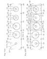
- the variant-shaped laminated core 10 is produced by punching from a strip material (for example, a silicon steel strip of 0.15-0.5 mm thickness) 11, an example of a strip to be processed, to produce core sheets 12-14 of plural (in the present embodiment, three) different types as regards the size, a required number of core sheets for each type, and by laminating and interlocking the punched out core sheets 12-14.
- the variant-shaped laminated core 10 includes a first variant-shaped core 15 located at the lowest position, a second variant-shaped core 16 located on the first variant-shaped core 15, and a third variant-shaped core 17 located on the second variant-shaped core 16.
- the first variant-shaped core 15 is obtained by laminating and interlocking plural (for example, about three to ten) core sheets 12 which are circular when viewed from the top.
- the second variant-shaped core 16 is obtained by laminating and interlocking plural (for example, about three to ten) core sheets 13 which are circular when viewed from the top.
- the third variant-shaped core 17 is obtained by laminating and interlocking plural (for example, about three to ten) core sheets 14 which are circular when viewed from the top.
- the lowermost core sheet 13 of the second variant-shaped core 16 is also laminated on, and interlocked with, the uppermost core sheet 12 of the first variant-shaped core 15.
- the lowermost core sheet 14 of the third variant-shaped core 17 is also laminated on, and interlocked with, the uppermost core sheet 13 of the second variant-shaped core 16.
- the core sheet 12, which constitutes the first variant-shaped core 15, and the core sheet 14, which constitutes the third variant-shaped core 17, are the same in outer diameter, while shaft holes 18 and 19 of the respective core sheets 12 and 14 formed in central areas thereof are located 180° apart from each other with respect to the centers of the core sheets 12 and 14.
- the core sheet 13, which constitutes the second variant-shaped core 16, is smaller in outer diameter than the core sheets 12 and 14, while a shaft hole 20 is coaxial with the core sheet 13.
- caulking portions 21 are arranged circumferentially equidistantly about each of the shaft holes 18-20 of the respective core sheets 12-14 and with each of the axes of the shaft holes 18-20 as a center.
- the core sheets 12-14 are laminated and interlocked.
- the core sheets 12-14 are laminated and interlocked.
- the strip material 11 for example, a silicon steel strip of 0.15-0.5 mm thickness
- the strip material 11 is introduced into a pressing equipment adapted to perform pressing operations at least in Step A to Step D sequentially.
- the strip material 11 is transferred from Step A to Step D sequentially in an intermittent manner that is based on pilot holes 22 and 23.
- the pilot holes 22 and pilot holes 23 are formed at a predetermined pitch on the lateral sides of the strip material 11. Also, the shaft holes 18-20 for the respective core sheets 12-14 are formed each at the middle between the lateral sides of the strip material 11.
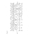
- Step A using a punch and a die (unillustrated), the outline of the circular core sheet 12, which constitutes the first variant-shaped core 15, is punched out, from the strip material 11 being transferred. While being held between the upper face of an ascent-and-descent platform in the die and the lower face of the punch, the punched out core sheet 12 is pushed back (by being lifted) into its initial position in the strip material 11.
- the core sheet 12 is made separate from a punched hole 24 of the strip material 11 but hard to come off the punched hole 24.
- the above operation is repeated for the number of the core sheets 12 required for production of the first variant-shaped core 15 (here, two sheets are shown for simplicity). Thus, the core sheets 12 are obtained.
- the above operation is preformed also for the core sheets 13, which constitute the second variant-shaped core 16, and for the core sheets 14, which constitute the third variant-shaped core 17, and then, the core sheets 13 and 14 are pushed back into their initial positions at punched holes 25 and 26, respectively, of the strip material 11.
- the core sheets 12-14 which constitute the first to third variant-shaped cores 15-17, are sequentially punched out to form the outlines of the core sheets 12-14 in the following order: the core sheets 12, the core sheets 13, and the core sheets 14.
- the core sheets 12-14 are illustrated as if they were punched out in the following order: the core sheets 14, the core sheets 13, and the core sheets 12. It is to be noted that dies and punches for blanking out the cores 13 and 14 halt their motions until a portion of the strip material 11 to be the core sheet 12 arrives at the punch and the die for blanking out the core sheet 12.
- the dies and the punches for blanking out the core sheets 12 and 14 halt their motions when the core sheet 13 passes these dies and punches, and the dies and the punches for blanking out the core sheets 12 and 13 halt their motions when the core sheet 14 passes these dies and punches.
- Step B as shown in FIG. 2(B) , the outlines of two opposed cutouts 28 are formed using dies and punches.
- the two cutouts 28 have inner edges in contact with the core sheet 12 punched out in Step A, and reach outer edges of an outer plate 27 to be formed to contain thereinside the core sheet 12.
- the outlines of two cutouts 30 and the outlines of two cutouts 32 are formed using dies and punches.
- the two cutouts 30 reach outer edges of an outer plate 29 to be formed to contain thereinside the core sheet 13.
- the two cutouts 32 reach outer edges of an outer plate 31 to be formed to contain thereinside the core sheet 14.
- Four or more cutouts may be formed depending on the shape of a variant-shaped laminated core to be produced. In such a case, the angle made by the adjacent cutouts with respect to the center of the outer plate is 180 degrees or less.
- the outer plate 27 is the same in outer shape as the outer plates 29 and 31, and thus these outer plates can be punched out by the same die device. In order to improve the material yield, it is desirable to have a shortest distance of at least 1-5 mm between the punched holes 24-26 of the strip material 11 and the outer peripheries of the outer plates 27, 29 and 31 which are to be made by punching.
- Step C plural (in this embodiment, six) caulking portions 21 are formed in the core sheet 12 (in this embodiment circumferentially equidistantly about the shaft hole 18). Also, plural (in this embodiment, four) caulking portions 33 are formed in the outer plate 27 (in this embodiment, at corners thereof) but not in the core sheet 12. The caulking portions 21 and the caulking portions 33 are formed simultaneously. However, the formation of the caulking portions 21 in the core sheets 12-14 may be carried out separately from the formation of the caulking portions 33 in outer plates 27, 29 and 31, using different die devices at different places.
- caulking holes to be the caulking portions 21 are formed in the lowest core sheet 12, and caulking holes to be the caulking portions 33 are formed in the lowest outer plate 27, using dies and punches.
- caulking projections to be the caulking portions 21 are formed in the core sheets 12 other than the lowest core sheet 12, and caulking projections to be the caulking portions 33 are formed in the outer plates 27 other than the lowest outer plate 27, using dies and punches.
- caulking projections to be the caulking portions 21 are formed in the core sheets 13 and 14, and caulking projections to be the caulking portions 33 are formed in the outer plates 29 and 31, in the same manner using dies and punches.
- Step D using outline-forming blanking die and punch, which make a die device, the outer plate 27 in which the core sheet 12 is fitted, is punched out from the strip material 11 to form the outline.
- the punched out outer plates 27 with the core sheets 12 are dropped in the blanking die, and sequentially laminated and interlocked in the die device.
- the core sheets 13 and the outer plates 29 holding the core sheets 13 therein are sequentially laminated and interlocked on the uppermost core sheet 12 and outer plate 27. Then, the core sheets 14 and the outer plates 31 having the core sheets 14 therein are sequentially laminated and interlocked further on the now uppermost core sheet 13 and outer plate 29.
- the plural core sheets of the same configuration are laminated one on another, and the vertically adjacent core sheets 12 and 13 and the vertically adjacent core sheets 13 and 14 are laminated and interlocked together.
- Step E as shown in FIGS. 1(A) and 1(B) , the laminated outer plates 27, 29 and 31, located outside the variant-shaped laminated core 10 formed by the laminated and interlocked core sheets 12-14, are drawn apart from the variant-shaped laminated core 10 in opposite directions at the cutouts 28, 30 and 32 to remove the laminated outer plates 27, 29 and 31 from the laminated core sheets 12-14.
- Steps A-E are carried out sequentially in this order: Step A of punching out the outlines of the core sheets 12-14 from the strip material 11 and then pushing back the punched out core sheets 12-14 into the strip material 11; Step B of forming the cutouts 28, 30 and 32; Step C of forming the caulking portions 21 and 33; Step D of laminating and interlocking the core sheets 12-14, to produce the variant-shaped laminated core 10, and laminating and interlocking the outer plates 27, 29 and 31 containing the core sheets 12-14 therein; and Step E of removing the laminated outer plates 27, 29 and 31 located outside the variant-shaped laminated core 10.
- the order is not limited to the above.
- Step C may be carried out after Step A
- Step B may be carried out either before Step A or between Step C and Step D.
- Carrying out Step C after Step A eliminates the risk of crushing the formed caulking portions, thereby to enable reliable lamination and interlocking of the core sheets and the outer plates.
- Carrying out Step B before Step A, or between Step A and Step C, or between Step C and Step D permits easy separation of the laminated and interlocked outer plates from the laminated and interlocked core sheets at the cutouts.
- the variant-shaped laminated core 10 can be produced as shown in FIGS. 5(A) and 5(B) .
- a shaft is inserted into the shaft holes 18-20 of the produced variant-shaped laminated core 10, and the variant-shaped laminated core 10 is subjected to predetermined processes, and after that, incorporated into a reluctance type resolver or a variable reluctance type resolver for use.
- variant-shaped laminated cores may be produced from core sheets of plural different types as regards the outer shape, and further, they may be produced from core sheets of plural different types as regards both the outer shape and size.
- core sheets shown are circular when viewed from the top, the shape of the core sheets is not limited to a circle, and may be any as long as they are usable in reluctance type resolvers or variable reluctance type resolvers.
- the caulking portions in the core sheets and those in the outer plates are formed simultaneously, they may be formed in separate steps. Further, the formation of the caulking portions in the outer plates in the embodiment may be omitted.
- the present invention permits application of a production scheme using progressive press die equipment to the production of variant-shaped laminated cores.
- the present invention eliminates the conventional need to punch out and laminate a greater number of core sheets of each of plural types than required for production of a single variant-shaped laminated core and to extract, from the laminated core sheets, a portion of core sheets to be integrated in a variant-shaped laminated core. Consequently, the present invention permits dramatic improvement in productivity of variant-shaped laminated cores.
Landscapes
- Engineering & Computer Science (AREA)
- Power Engineering (AREA)
- Manufacturing & Machinery (AREA)
- Mechanical Engineering (AREA)
- Manufacture Of Motors, Generators (AREA)
- Manufacturing Cores, Coils, And Magnets (AREA)
Claims (7)
- Verfahren zur Herstellung eines unregelmäßig geformten laminierten Kerns (10) durch Ausstanzen von mehreren in Bezug auf äußere Form und/oder Größe unterschiedlichen Typen von Kernschichten (12-14) aus einem zu verarbeitenden Band (11) und durch Laminieren und Verschachteln der mehreren Typen von Kernschichten (12-14), wobei das Verfahren aufweist:Schritt A: Ausstanzen einer erforderlichen Anzahl von Kernschichten (12-14) für jeden der mehreren Typen aus dem transferierten Band (11), um die Umrisslinien der Kernschichten (12-14) zu bilden, und Zurückstoßen der ausgestanzten Kernschichten (12-14) in das Band (11);Schritt B: Bilden von mindestens zwei gegenüberliegenden Ausschnitten (28,30,32), wobei die Ausschnitte (28,30,32) eine äußere Begrenzung jeder von äußeren Platten (27,29,31) erreichen, wobei die äußeren Platten (27,29,31) gleiche Außenform haben und darin jeweils die Kernschichten (12-14) enthalten, wobei die Ausschnitte (28,30,32) jeweils Innenkannten haben, die jeweils die Kernschichten (12-14) erreichen;Schritt C: Bilden von Versiegelungsabschnitten (21) zum Verschachteln in jeder der Kernschichten (12-14);Schritt D: Ausstanzen der äußeren Platten (27,29,31) aus dem Band (11), um die Umrisslinien der äußeren Platten (27,29,31) zu bilden, und Laminieren und Verschachteln der Kernschichten (12-14), um den unregelmäßig geformten laminierten Kern (10) zu bilden; undSchritt E: Entfernen der äußeren Platten (27,29,31), die außerhalb des laminierten und verschachtelten unregelmäßig geformten Kerns (10) angeordnet sind.
- Verfahren nach Anspruch 1, wobei in Schritt C Versiegelungsabschnitte (33) zum Verschachteln auch in jeder der äußeren Platten (27,29,31) gebildet werden und in Schritt D auch die äußeren Platten (27,29,31) laminiert und verschachtelt werden.
- Verfahren nach Anspruch 2, wobei die Bildung der Versiegelungsabschnitte (33) in jeder der äußeren Platten (27,29,31) gleichzeitig mit der Bildung der Versiegelungsabschnitte (21) in jeder der Kernschichten (12-14) ausgeführt wird.
- Verfahren nach Anspruch 2, wobei die Bildung der Versiegelungsabschnitte (33) in jeder der äußeren Platten (27,29,31) getrennt von der Bildung der Versiegelungsabschnitte (21) in jeder der Kernschichten (12-14) ausgeführt wird.
- Verfahren nach einem der Ansprüche 1 bis 4, wobei:1) Schritt C nach Schritt A ausgeführt wird und2) Schritt B vor Schritt A oder zwischen Schritt A und Schritt C oder zwischen Schritt C und Schritt D ausgeführt wird.
- Verfahren nach einem der Ansprüche 1 bis 5, wobei für jeden Typ von Kernschichten (12-14) die mehreren Kernschichten (12-14) derselben Konfiguration aneinander laminiert werden.
- Verfahren nach einem der Ansprüche 1 bis 5, wobei das Entfernen der äußeren Platten (27,29,31), die außerhalb des laminierten und verschachtelten unregelmäßig geformten Kerns (10) angeordnet sind, dadurch ausgeführt wird, dass die äußeren Platten (27,29,31) bezüglich der Ausschnitte (28,30,32) voneinander weg gezogen werden.
Priority Applications (1)
| Application Number | Priority Date | Filing Date | Title |
|---|---|---|---|
| SI200831413T SI2138807T1 (sl) | 2007-04-25 | 2008-04-14 | Postopek izdelave nepravilno oblikovanega lameliranega jedra in nepravilno oblikovano lamelirano jedro, ki je izdelano z uporabo postopka |
Applications Claiming Priority (2)
| Application Number | Priority Date | Filing Date | Title |
|---|---|---|---|
| JP2007115887 | 2007-04-25 | ||
| PCT/JP2008/057294 WO2008133090A1 (ja) | 2007-04-25 | 2008-04-14 | 異形積層コアの製造方法及びこれを用いて製造した異形積層コア |
Publications (3)
| Publication Number | Publication Date |
|---|---|
| EP2138807A1 EP2138807A1 (de) | 2009-12-30 |
| EP2138807A4 EP2138807A4 (de) | 2013-03-06 |
| EP2138807B1 true EP2138807B1 (de) | 2015-01-21 |
Family
ID=39925548
Family Applications (1)
| Application Number | Title | Priority Date | Filing Date |
|---|---|---|---|
| EP08740380.4A Active EP2138807B1 (de) | 2007-04-25 | 2008-04-14 | Verfahren zur herstellung eines unregelmässig geformten laminatkerns und mit diesem verfahren hergestellter unregelmässig geformter laminatkern |
Country Status (6)
| Country | Link |
|---|---|
| US (1) | US8136229B2 (de) |
| EP (1) | EP2138807B1 (de) |
| JP (1) | JP4219400B2 (de) |
| CN (1) | CN101641572B (de) |
| SI (1) | SI2138807T1 (de) |
| WO (1) | WO2008133090A1 (de) |
Families Citing this family (8)
| Publication number | Priority date | Publication date | Assignee | Title |
|---|---|---|---|---|
| JP5160944B2 (ja) * | 2008-04-21 | 2013-03-13 | 黒田精工株式会社 | 積層鉄心の製造方法及び製造装置 |
| CN102035277B (zh) * | 2009-10-07 | 2014-08-20 | 阿斯莫有限公司 | 电动机 |
| KR101931790B1 (ko) * | 2014-03-04 | 2018-12-21 | 구로다 프리시젼 인더스트리스 리미티드 | 순차 이송 금형 장치용 배압 장치 및 이를 구비한 순차 이송 금형 장치 |
| DE112015005146T5 (de) * | 2014-11-14 | 2017-07-27 | Mitsui High-Tec, Inc. | Laminierter Eisenkern und Verfahren zum Herstellen desselben |
| JP6797039B2 (ja) * | 2017-01-25 | 2020-12-09 | 株式会社三井ハイテック | 積層鉄心の製造方法及び積層鉄心の製造装置 |
| JP7137918B2 (ja) * | 2017-10-16 | 2022-09-15 | 株式会社三井ハイテック | 積層鉄心の製造方法 |
| JP6764463B2 (ja) * | 2018-12-21 | 2020-09-30 | 株式会社三井ハイテック | 積層鉄心の製造方法 |
| DE112021006296T5 (de) | 2021-10-25 | 2023-11-09 | Kuroda Precision Industries Ltd. | Klebstoffauftragsvorrichtung und klebstoffauftragsverfahren für einen laminierten eisenkern sowie herstellungsvorrichtung und herstellungsverfahren für einen laminierten eisenkern |
Family Cites Families (18)
| Publication number | Priority date | Publication date | Assignee | Title |
|---|---|---|---|---|
| WO1982003491A1 (fr) * | 1981-03-31 | 1982-10-14 | Hara Yoshihumi | Dispositif de fabrication d'un lamine a noyau de fer |
| US4427462A (en) * | 1981-06-18 | 1984-01-24 | Matsushita Electric Industrial Co., Ltd. | Electric apparatus and its magnetic core of (100)[011] silicon-iron sheet made by rapid quenching method |
| JPS58116033A (ja) * | 1981-12-29 | 1983-07-11 | Kuroda Precision Ind Ltd | 積層鉄心およびその金型装置 |
| JPS6077647A (ja) * | 1983-10-03 | 1985-05-02 | Mitsui Haitetsuku:Kk | 積層鉄芯の製造装置 |
| KR910002991B1 (ko) * | 1987-07-20 | 1991-05-11 | 미쯔비시 덴끼 가부시끼가이샤 | 아마추어 |
| DE3929331C2 (de) * | 1989-09-04 | 1990-12-13 | Buehler Gmbh Nachf Geb | Verfahren zur Herstellung und zum Bewickeln von für Elektro-Motore mit Innenläufer bestimmten Statorblechpaketen |
| FR2672987A1 (fr) * | 1991-02-19 | 1992-08-21 | Mecanique Magnetique Sa | Capteur angulaire, notamment pour machines tournantes a tres grande vitesse de rotation. |
| JPH0556607A (ja) * | 1991-08-26 | 1993-03-05 | Mitsui High Tec Inc | スキユー形状可変積層鉄心の製造法およびその製造金型 装置 |
| JP2887430B2 (ja) * | 1993-06-21 | 1999-04-26 | 株式会社三井ハイテック | 積層鉄心の製造方法 |
| JP3568364B2 (ja) * | 1996-09-30 | 2004-09-22 | 松下電器産業株式会社 | 回転電機のコア |
| JP2002039794A (ja) | 2000-07-24 | 2002-02-06 | Fuji Heavy Ind Ltd | リラクタンス型レゾルバのロータ保護構造 |
| JP3786854B2 (ja) * | 2001-08-30 | 2006-06-14 | 株式会社三井ハイテック | 積層鉄心の製造方法 |
| JP3869731B2 (ja) * | 2002-01-17 | 2007-01-17 | 株式会社三井ハイテック | アモルファス積層コアの製造方法 |
| US7038349B2 (en) * | 2003-03-18 | 2006-05-02 | Asmo Co., Ltd. | Stator for dynamo-electric machine |
| JP4034690B2 (ja) * | 2003-04-28 | 2008-01-16 | ミネベア株式会社 | 2重化バリアブルリラクタンスレゾルバおよびそれを用いた複速度レゾルバシステム |
| JP2005103638A (ja) * | 2003-09-10 | 2005-04-21 | Aisin Aw Co Ltd | モータ用積層コアの製造方法、その製造装置、及び積層治具 |
| JP4158858B2 (ja) | 2003-12-04 | 2008-10-01 | 多摩川精機株式会社 | 回転角度検出器 |
| JP2007020386A (ja) * | 2005-06-08 | 2007-01-25 | Denso Corp | 回転電機 |
-
2008
- 2008-04-14 SI SI200831413T patent/SI2138807T1/sl unknown
- 2008-04-14 WO PCT/JP2008/057294 patent/WO2008133090A1/ja not_active Ceased
- 2008-04-14 CN CN200880009720.7A patent/CN101641572B/zh active Active
- 2008-04-14 US US12/440,492 patent/US8136229B2/en active Active
- 2008-04-14 JP JP2008527231A patent/JP4219400B2/ja active Active
- 2008-04-14 EP EP08740380.4A patent/EP2138807B1/de active Active
Also Published As
| Publication number | Publication date |
|---|---|
| US8136229B2 (en) | 2012-03-20 |
| US20100043202A1 (en) | 2010-02-25 |
| CN101641572A (zh) | 2010-02-03 |
| WO2008133090A1 (ja) | 2008-11-06 |
| EP2138807A4 (de) | 2013-03-06 |
| JP4219400B2 (ja) | 2009-02-04 |
| SI2138807T1 (sl) | 2015-05-29 |
| CN101641572B (zh) | 2012-05-09 |
| JPWO2008133090A1 (ja) | 2010-07-22 |
| EP2138807A1 (de) | 2009-12-30 |
Similar Documents
| Publication | Publication Date | Title |
|---|---|---|
| US8136229B2 (en) | Method of producing variant-shaped laminated core | |
| US8048509B2 (en) | Laminated core and method of producing laminated core | |
| CN102111042B (zh) | 层叠铁心的制造方法 | |
| CN102428627B (zh) | 制造叠片铁芯的方法以及叠片铁芯 | |
| CN104756374B (zh) | 层叠铁芯的生产方法 | |
| KR100990969B1 (ko) | 모터용 코어 제조를 위한 금형 장치 | |
| CN107404201A (zh) | 层叠铁心的制造方法 | |
| CN101828321A (zh) | 定子层叠铁芯及其制造方法 | |
| JP4472417B2 (ja) | 積層鉄心の製造方法および金型装置 | |
| US10040111B2 (en) | Method of manufacturing laminated iron core | |
| JP5276303B2 (ja) | 回転電機の回転子積層鉄心の製造方法 | |
| US11752537B2 (en) | Metal parts blanking process for rotor and stator of an electric motor | |
| CN102005869A (zh) | 电机定转子片冲转子槽落料冲压工艺及其关键模具 | |
| CN105471196B (zh) | 叠片铁芯的制造方法及制造装置 | |
| JP5338190B2 (ja) | 積層鉄心の製造装置および製造方法 | |
| EP2782223B1 (de) | Herstellungsverfahren und Herstellungsvorrichtung für einen geblechten Kern | |
| JP5209095B2 (ja) | 鉄心片の製造設備 | |
| KR101881257B1 (ko) | 적층코아 및, 그 제조방법 | |
| JP2010178487A (ja) | 積層鉄心の製造方法および順送り金型装置 | |
| JP4898240B2 (ja) | 鉄心片の製造方法 | |
| JP2003116252A (ja) | 非対称抜孔を有するモータ用鉄芯のプレス自動転積方法 | |
| KR100991243B1 (ko) | 모터 및 모터용 코어 제조를 위한 금형 장치와 이를 이용한모터 제조 방법 | |
| JP4912088B2 (ja) | 積層鉄心の製造方法および製造装置 | |
| JP2008278753A (ja) | 積層鉄心の製造方法及び金型装置 | |
| KR102704728B1 (ko) | 모터 코어 제조방법 |
Legal Events
| Date | Code | Title | Description |
|---|---|---|---|
| PUAI | Public reference made under article 153(3) epc to a published international application that has entered the european phase |
Free format text: ORIGINAL CODE: 0009012 |
|
| 17P | Request for examination filed |
Effective date: 20090908 |
|
| AK | Designated contracting states |
Kind code of ref document: A1 Designated state(s): AT BE BG CH CY CZ DE DK EE ES FI FR GB GR HR HU IE IS IT LI LT LU LV MC MT NL NO PL PT RO SE SI SK TR |
|
| DAX | Request for extension of the european patent (deleted) | ||
| A4 | Supplementary search report drawn up and despatched |
Effective date: 20130206 |
|
| RIC1 | Information provided on ipc code assigned before grant |
Ipc: G01D 5/245 20060101AFI20130131BHEP |
|
| 17Q | First examination report despatched |
Effective date: 20131127 |
|
| GRAP | Despatch of communication of intention to grant a patent |
Free format text: ORIGINAL CODE: EPIDOSNIGR1 |
|
| INTG | Intention to grant announced |
Effective date: 20140915 |
|
| GRAS | Grant fee paid |
Free format text: ORIGINAL CODE: EPIDOSNIGR3 |
|
| GRAA | (expected) grant |
Free format text: ORIGINAL CODE: 0009210 |
|
| AK | Designated contracting states |
Kind code of ref document: B1 Designated state(s): AT BE BG CH CY CZ DE DK EE ES FI FR GB GR HR HU IE IS IT LI LT LU LV MC MT NL NO PL PT RO SE SI SK TR |
|
| REG | Reference to a national code |
Ref country code: GB Ref legal event code: FG4D |
|
| REG | Reference to a national code |
Ref country code: CH Ref legal event code: EP |
|
| REG | Reference to a national code |
Ref country code: IE Ref legal event code: FG4D |
|
| REG | Reference to a national code |
Ref country code: AT Ref legal event code: REF Ref document number: 707742 Country of ref document: AT Kind code of ref document: T Effective date: 20150215 |
|
| REG | Reference to a national code |
Ref country code: DE Ref legal event code: R096 Ref document number: 602008036451 Country of ref document: DE Effective date: 20150312 |
|
| REG | Reference to a national code |
Ref country code: NL Ref legal event code: VDEP Effective date: 20150121 |
|
| REG | Reference to a national code |
Ref country code: AT Ref legal event code: MK05 Ref document number: 707742 Country of ref document: AT Kind code of ref document: T Effective date: 20150121 |
|
| REG | Reference to a national code |
Ref country code: LT Ref legal event code: MG4D |
|
| PG25 | Lapsed in a contracting state [announced via postgrant information from national office to epo] |
Ref country code: SE Free format text: LAPSE BECAUSE OF FAILURE TO SUBMIT A TRANSLATION OF THE DESCRIPTION OR TO PAY THE FEE WITHIN THE PRESCRIBED TIME-LIMIT Effective date: 20150121 Ref country code: FI Free format text: LAPSE BECAUSE OF FAILURE TO SUBMIT A TRANSLATION OF THE DESCRIPTION OR TO PAY THE FEE WITHIN THE PRESCRIBED TIME-LIMIT Effective date: 20150121 Ref country code: BG Free format text: LAPSE BECAUSE OF FAILURE TO SUBMIT A TRANSLATION OF THE DESCRIPTION OR TO PAY THE FEE WITHIN THE PRESCRIBED TIME-LIMIT Effective date: 20150421 Ref country code: NO Free format text: LAPSE BECAUSE OF FAILURE TO SUBMIT A TRANSLATION OF THE DESCRIPTION OR TO PAY THE FEE WITHIN THE PRESCRIBED TIME-LIMIT Effective date: 20150421 Ref country code: ES Free format text: LAPSE BECAUSE OF FAILURE TO SUBMIT A TRANSLATION OF THE DESCRIPTION OR TO PAY THE FEE WITHIN THE PRESCRIBED TIME-LIMIT Effective date: 20150121 Ref country code: LT Free format text: LAPSE BECAUSE OF FAILURE TO SUBMIT A TRANSLATION OF THE DESCRIPTION OR TO PAY THE FEE WITHIN THE PRESCRIBED TIME-LIMIT Effective date: 20150121 Ref country code: HR Free format text: LAPSE BECAUSE OF FAILURE TO SUBMIT A TRANSLATION OF THE DESCRIPTION OR TO PAY THE FEE WITHIN THE PRESCRIBED TIME-LIMIT Effective date: 20150121 |
|
| PG25 | Lapsed in a contracting state [announced via postgrant information from national office to epo] |
Ref country code: NL Free format text: LAPSE BECAUSE OF FAILURE TO SUBMIT A TRANSLATION OF THE DESCRIPTION OR TO PAY THE FEE WITHIN THE PRESCRIBED TIME-LIMIT Effective date: 20150121 Ref country code: IS Free format text: LAPSE BECAUSE OF FAILURE TO SUBMIT A TRANSLATION OF THE DESCRIPTION OR TO PAY THE FEE WITHIN THE PRESCRIBED TIME-LIMIT Effective date: 20150521 Ref country code: LV Free format text: LAPSE BECAUSE OF FAILURE TO SUBMIT A TRANSLATION OF THE DESCRIPTION OR TO PAY THE FEE WITHIN THE PRESCRIBED TIME-LIMIT Effective date: 20150121 Ref country code: GR Free format text: LAPSE BECAUSE OF FAILURE TO SUBMIT A TRANSLATION OF THE DESCRIPTION OR TO PAY THE FEE WITHIN THE PRESCRIBED TIME-LIMIT Effective date: 20150422 Ref country code: AT Free format text: LAPSE BECAUSE OF FAILURE TO SUBMIT A TRANSLATION OF THE DESCRIPTION OR TO PAY THE FEE WITHIN THE PRESCRIBED TIME-LIMIT Effective date: 20150121 Ref country code: PL Free format text: LAPSE BECAUSE OF FAILURE TO SUBMIT A TRANSLATION OF THE DESCRIPTION OR TO PAY THE FEE WITHIN THE PRESCRIBED TIME-LIMIT Effective date: 20150121 |
|
| REG | Reference to a national code |
Ref country code: DE Ref legal event code: R097 Ref document number: 602008036451 Country of ref document: DE |
|
| PG25 | Lapsed in a contracting state [announced via postgrant information from national office to epo] |
Ref country code: CZ Free format text: LAPSE BECAUSE OF FAILURE TO SUBMIT A TRANSLATION OF THE DESCRIPTION OR TO PAY THE FEE WITHIN THE PRESCRIBED TIME-LIMIT Effective date: 20150121 Ref country code: RO Free format text: LAPSE BECAUSE OF FAILURE TO SUBMIT A TRANSLATION OF THE DESCRIPTION OR TO PAY THE FEE WITHIN THE PRESCRIBED TIME-LIMIT Effective date: 20150121 Ref country code: EE Free format text: LAPSE BECAUSE OF FAILURE TO SUBMIT A TRANSLATION OF THE DESCRIPTION OR TO PAY THE FEE WITHIN THE PRESCRIBED TIME-LIMIT Effective date: 20150121 Ref country code: SK Free format text: LAPSE BECAUSE OF FAILURE TO SUBMIT A TRANSLATION OF THE DESCRIPTION OR TO PAY THE FEE WITHIN THE PRESCRIBED TIME-LIMIT Effective date: 20150121 Ref country code: DK Free format text: LAPSE BECAUSE OF FAILURE TO SUBMIT A TRANSLATION OF THE DESCRIPTION OR TO PAY THE FEE WITHIN THE PRESCRIBED TIME-LIMIT Effective date: 20150121 |
|
| PLBE | No opposition filed within time limit |
Free format text: ORIGINAL CODE: 0009261 |
|
| STAA | Information on the status of an ep patent application or granted ep patent |
Free format text: STATUS: NO OPPOSITION FILED WITHIN TIME LIMIT |
|
| PG25 | Lapsed in a contracting state [announced via postgrant information from national office to epo] |
Ref country code: MC Free format text: LAPSE BECAUSE OF FAILURE TO SUBMIT A TRANSLATION OF THE DESCRIPTION OR TO PAY THE FEE WITHIN THE PRESCRIBED TIME-LIMIT Effective date: 20150121 Ref country code: LU Free format text: LAPSE BECAUSE OF FAILURE TO SUBMIT A TRANSLATION OF THE DESCRIPTION OR TO PAY THE FEE WITHIN THE PRESCRIBED TIME-LIMIT Effective date: 20150414 |
|
| REG | Reference to a national code |
Ref country code: CH Ref legal event code: PL |
|
| GBPC | Gb: european patent ceased through non-payment of renewal fee |
Effective date: 20150421 |
|
| 26N | No opposition filed |
Effective date: 20151022 |
|
| REG | Reference to a national code |
Ref country code: IE Ref legal event code: MM4A |
|
| PG25 | Lapsed in a contracting state [announced via postgrant information from national office to epo] |
Ref country code: GB Free format text: LAPSE BECAUSE OF NON-PAYMENT OF DUE FEES Effective date: 20150421 Ref country code: LI Free format text: LAPSE BECAUSE OF NON-PAYMENT OF DUE FEES Effective date: 20150430 Ref country code: CH Free format text: LAPSE BECAUSE OF NON-PAYMENT OF DUE FEES Effective date: 20150430 |
|
| REG | Reference to a national code |
Ref country code: FR Ref legal event code: PLFP Year of fee payment: 9 |
|
| PG25 | Lapsed in a contracting state [announced via postgrant information from national office to epo] |
Ref country code: IE Free format text: LAPSE BECAUSE OF NON-PAYMENT OF DUE FEES Effective date: 20150414 |
|
| PG25 | Lapsed in a contracting state [announced via postgrant information from national office to epo] |
Ref country code: BE Free format text: LAPSE BECAUSE OF FAILURE TO SUBMIT A TRANSLATION OF THE DESCRIPTION OR TO PAY THE FEE WITHIN THE PRESCRIBED TIME-LIMIT Effective date: 20150121 |
|
| PGFP | Annual fee paid to national office [announced via postgrant information from national office to epo] |
Ref country code: FR Payment date: 20160423 Year of fee payment: 9 Ref country code: IT Payment date: 20160429 Year of fee payment: 9 Ref country code: SI Payment date: 20160323 Year of fee payment: 9 |
|
| PG25 | Lapsed in a contracting state [announced via postgrant information from national office to epo] |
Ref country code: MT Free format text: LAPSE BECAUSE OF FAILURE TO SUBMIT A TRANSLATION OF THE DESCRIPTION OR TO PAY THE FEE WITHIN THE PRESCRIBED TIME-LIMIT Effective date: 20150121 |
|
| PG25 | Lapsed in a contracting state [announced via postgrant information from national office to epo] |
Ref country code: HU Free format text: LAPSE BECAUSE OF FAILURE TO SUBMIT A TRANSLATION OF THE DESCRIPTION OR TO PAY THE FEE WITHIN THE PRESCRIBED TIME-LIMIT; INVALID AB INITIO Effective date: 20080414 |
|
| PG25 | Lapsed in a contracting state [announced via postgrant information from national office to epo] |
Ref country code: CY Free format text: LAPSE BECAUSE OF FAILURE TO SUBMIT A TRANSLATION OF THE DESCRIPTION OR TO PAY THE FEE WITHIN THE PRESCRIBED TIME-LIMIT Effective date: 20150121 |
|
| PG25 | Lapsed in a contracting state [announced via postgrant information from national office to epo] |
Ref country code: PT Free format text: LAPSE BECAUSE OF FAILURE TO SUBMIT A TRANSLATION OF THE DESCRIPTION OR TO PAY THE FEE WITHIN THE PRESCRIBED TIME-LIMIT Effective date: 20150521 |
|
| PG25 | Lapsed in a contracting state [announced via postgrant information from national office to epo] |
Ref country code: TR Free format text: LAPSE BECAUSE OF FAILURE TO SUBMIT A TRANSLATION OF THE DESCRIPTION OR TO PAY THE FEE WITHIN THE PRESCRIBED TIME-LIMIT Effective date: 20150121 |
|
| REG | Reference to a national code |
Ref country code: FR Ref legal event code: ST Effective date: 20171229 |
|
| PG25 | Lapsed in a contracting state [announced via postgrant information from national office to epo] |
Ref country code: FR Free format text: LAPSE BECAUSE OF NON-PAYMENT OF DUE FEES Effective date: 20170502 |
|
| PG25 | Lapsed in a contracting state [announced via postgrant information from national office to epo] |
Ref country code: SI Free format text: LAPSE BECAUSE OF NON-PAYMENT OF DUE FEES Effective date: 20170415 |
|
| REG | Reference to a national code |
Ref country code: SI Ref legal event code: KO00 Effective date: 20180111 |
|
| PG25 | Lapsed in a contracting state [announced via postgrant information from national office to epo] |
Ref country code: IT Free format text: LAPSE BECAUSE OF NON-PAYMENT OF DUE FEES Effective date: 20170414 |
|
| PGFP | Annual fee paid to national office [announced via postgrant information from national office to epo] |
Ref country code: DE Payment date: 20260305 Year of fee payment: 19 |