EP2138799A2 - Geschützrohr - Google Patents
Geschützrohr Download PDFInfo
- Publication number
- EP2138799A2 EP2138799A2 EP09006380A EP09006380A EP2138799A2 EP 2138799 A2 EP2138799 A2 EP 2138799A2 EP 09006380 A EP09006380 A EP 09006380A EP 09006380 A EP09006380 A EP 09006380A EP 2138799 A2 EP2138799 A2 EP 2138799A2
- Authority
- EP
- European Patent Office
- Prior art keywords
- bayonet
- gun barrel
- bottom piece
- core tube
- cavity
- Prior art date
- Legal status (The legal status is an assumption and is not a legal conclusion. Google has not performed a legal analysis and makes no representation as to the accuracy of the status listed.)
- Granted
Links
- 210000001520 comb Anatomy 0.000 claims description 13
- 230000000903 blocking effect Effects 0.000 claims description 8
- 238000010304 firing Methods 0.000 claims description 2
- 244000089486 Phragmites australis subsp australis Species 0.000 description 3
- 230000005540 biological transmission Effects 0.000 description 1
- 230000001419 dependent effect Effects 0.000 description 1
- 238000010348 incorporation Methods 0.000 description 1
- 239000000344 soap Substances 0.000 description 1
- 230000003313 weakening effect Effects 0.000 description 1
Images


Classifications
-
- F—MECHANICAL ENGINEERING; LIGHTING; HEATING; WEAPONS; BLASTING
- F41—WEAPONS
- F41A—FUNCTIONAL FEATURES OR DETAILS COMMON TO BOTH SMALLARMS AND ORDNANCE, e.g. CANNONS; MOUNTINGS FOR SMALLARMS OR ORDNANCE
- F41A21/00—Barrels; Gun tubes; Muzzle attachments; Barrel mounting means
- F41A21/48—Barrel mounting means, e.g. releasable mountings for replaceable barrels
- F41A21/481—Barrel mounting means, e.g. releasable mountings for replaceable barrels using partial or interrupted threads, e.g. bayonet-type mountings
Definitions
- the invention relates to a gun barrel having a core tube and a bottom piece, which are connected to one another via a bayonet thread, wherein a contiguous cavity remains between adjacent bayonet combs of the core tube and the axially behind or before lying bayonet combs of the bottom piece.
- the bottom piece containing the closure is usually screwed onto the rear end region of the core tube in order to be able to replace the weapon barrel if necessary.
- a bayonet fitting DE 199 18 303 C2
- a groove in the core tube is provided in the one in the bottom piece of the weapon inserted key engages.
- the invention has for its object to provide a gun barrel of the type mentioned, in spite of the use of a bayonet thread for connecting the core tube to the bottom piece unintentional release of the core tube from the bottom piece is easily avoided in a simple manner.
- the invention is based essentially on the idea of inserting a blocking segment into at least one of the cavities resulting from a built-in core tube between adjacent bayonet combs of the core tube and the bottom piece, which should completely fill the corresponding cavity.
- this blocking segment can be inserted from the rear (that is to say through the closure space of the bottom piece) or from the front into the corresponding bottom piece after assembly of the core tube.
- the segments can also be contiguous to a ring.
- Fig. 1 shows a perspective view of a gun barrel 10 with a core tube 1 and a bottom piece 2, wherein the tube 1 in the rear area or at the rear end locking segment 3 are included, which are held together in this illustration via a segment ring 4 to a unit, but what not conditional.
- Fig. 2 shows the gun barrel 10 in a plan view.
- Fig. 3 is the section AA perpendicular to the tube axis of the located in the bottom piece 2 soul tube 1 reproduced.
- a blocking segment 3 which preferably completely fills the cavity 7 between the bayonet combs 6 of the core tube 1 and the bayonet combs of the bottom piece 2, not shown, so that upon firing a example spin-stabilized projectile on the Soelenrohr 1 acting swirl moment of the bayonet comb 6 of the core tube 1 on the locking segment 3 is completely transferred to the corresponding, axially adjacent bayonet comb of the bottom piece 2 and a rotation of the core tube 1 relative to the bottom piece 2 is not possible.
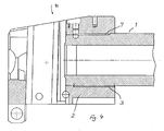
- Fig. 4 shows a further sectional view BB Fig. 2 ,
- the individual locking segment 3 is thereby pushed from the front over a depression in the core tube 1 in the space or cavity 7 between the tube 1 and bottom tube 2.
- blocking segments 3 are arranged in several or all cavities 7 between adjacent bayonet combs.
Landscapes
- Engineering & Computer Science (AREA)
- General Engineering & Computer Science (AREA)
- Toys (AREA)
- Earth Drilling (AREA)
Abstract
Description
- Die Erfindung betrifft ein Geschützrohr mit einem Seelenrohr und einem Bodenstück, die über ein Bajonettgewinde miteinander verbunden sind, wobei zwischen benachbarten Bajonettkämmen des Seelenrohres und den axial dahinter oder davor liegenden Bajonettkämmen des Bodenstückes ein zusammenhängender Hohlraum verbleibt.
- Bei großkalibrigen Geschützrohren wird das den Verschluss enthaltende Bodenstück üblicherweise auf den heckseitigen Endbereich des Seelenrohres aufgeschraubt, um das Waffenrohr gegebenenfalls auswechseln zu können. Um insbesondere bei Verwendung einer Bajonettverschraubung (
DE 199 18 303 C2 ) ein unbeabsichtigtes Herausdrehen des Seelenrohres aus dem Bodenstück zu verhindern und um die Drallmomente, die beim Schuss aus einem gezogenen Rohr entstehen, auf das Bodenstück zu übertragen, ist bei bekannten Geschützrohren eine Nut in dem Seelenrohr vorgesehen, in die eine in das Bodenstück der Waffe eingesetzte Passfeder greift. - Nachteilig ist bei Verwendung einer derartigen Verriegelungseinrichtung, dass die zur Übertragung des Drallmomentes auf das Bodenstück in das Seelenrohr eingefräste Nut eine Schwächung des Seelenrohres bewirkt, so dass die Lebensdauer des Seelenrohres verringert wird oder der Rohraußendurchmesser des Seelenrohres größer als bei Seelenrohren ohne eine derartige Nut gewählt werden muss.
- Der Erfindung liegt die Aufgabe zugrunde, ein Geschützrohr der eingangs erwähnten Art anzugeben, bei dem trotz Verwendung eines Bajonettgewindes zur Verbindung des Seelenrohres mit dem Bodenstück ein unbeabsichtigtes Lösen des Seelenrohres von dem Bodenstück auf einfache Weise sicher vermieden wird.
- Diese Aufgabe wird erfindungsgemäß durch die Merkmale des Anspruchs 1 gelöst. Weitere, besonders vorteilhafte Ausgestaltungen der Erfindung offenbaren die Unteransprüche.
- Die Erfindung beruht im Wesentlichen auf dem Gedanken, in mindestens einen der sich bei einem eingebauten Seelenrohr zwischen benachbarten Bajonettkämmen des Seelenrohres und des Bodenstückes ergebenden Hohlräume ein Sperrsegment einzulegen, das den entsprechenden Hohlraum komplett ausfüllen sollte. Dieses Sperrsegment kann nach der Montage des Seelenrohres, je nach Ausführungsform, von hinten (das heißt durch den Verschlussraum des Bodenstückes hindurch) oder von vorne in das entsprechende Bodenstück eingeschoben werden.
- Die Segmente können sich auch zusammenhängend an einem Ring befinden.
- Dies hat den Vorteil, dass keine zusätzliche Nut oder Bohrung im Seelenrohr erforderlich ist. Über diese Verriegelung werden die auftretende Drallmomente, die beim Schuss aus einem gezogenen Rohr auftreten, vom Rohr auf das Bodenstück übertragen, d.h., das auf das Rohr wirkende Drallmoment wird seitlich von dem Bajonettkamm des Rohres über das Segment auf den Bajonettkamm des Bodenstücks übertragen.
- Weitere Einzelheiten und Vorteile der Erfindung ergeben sich aus dem folgenden Ausführungsbeispiel.
- Es zeigt:
- Fig. 1
- eine perspektivische Darstellung eines Rohres und eines Bodenstücks mit Segmentring,
- Fig. 2
- eine Draufsichtdarstellung auf das Rohr mit Bodenstück aus
Fig. 1 , - Fig. 3
- eine Schnittdarstellung A-A senkrecht zur Rohrachse durch Rohr und Bo- denstück aus
Fig. 2 , - Fig. 4
- eine Schnittdarstellung B-B aus
Fig. 2 . -
Fig. 1 zeigt eine perspektivische Darstellung eines Geschützrohres 10 mit einem Seelenrohr 1 und einem Bodenstück 2, wobei um das Rohr 1 im hinteren Bereich bzw. am hinteren Ende Sperrsegment 3 eingebunden sind, die in dieser Darstellung über einen Segmentring 4 zu einer Einheit zusammengehalten werden, was aber nicht bedingend ist. -
Fig. 2 zeigt das Geschützrohr 10 in einer Draufsichtdarstellung. - In der
Fig. 3 ist der Schnitt A-A senkrecht zur Rohrachse des im Bodenstück 2 befindlichen Seelenrohres 1 wiedergegeben. Das beispielsweise mit Zügen und Feldern zum Verschießen drallstabilisierter Geschosse (nicht näher dargestellt) versehene Seelenrohr 1 und das Bodenstück 2 sind über ein Bajonettgewinde 5 miteinander verbunden, wobei im wiedergegebene Schnitt nur die Bajonettkämme 6 des Seelenrohres 1 zu sehen sind. - Zwischen benachbarten Bajonettkämmen 6 des Seelenrohres 1 (und damit auch zwischen den Bajonettkämmen des Bodenstückes 2, die sich in Richtung der Rohrachse fluchtend hinter bzw. vor den Bajonettkämmen des Seelenrohres befinden) sind Hohlräume 7 im Bodenstück 2 vorhanden.
- Erfindungsgemäß ist nun vorgesehen, in mindestens einen dieser Hohlräume 7 ein Sperrsegment 3 einzuschieben, welches den Hohlraum 7 zwischen den Bajonettkämmen 6 des Seelenrohres 1 und den nicht dargestellten Bajonettkämmen des Bodenstückes 2 vorzugsweise vollständig ausfüllt, so dass bei Schussabgabe eines beispielsweise drallstabilisierten Geschosses das auf das Seelenrohr 1 wirkende Drallmoment von dem Bajonettkamm 6 des Seelenrohres 1 über das Sperrsegment 3 vollständig auf den entsprechenden, axial benachbarten Bajonettkamm des Bodenstückes 2 übertragen wird und ein Verdrehen des Seelenrohres 1 gegenüber dem Bodenstück 2 nicht möglich ist.
-
Fig. 4 zeigt eine weitere Schnittdarstellung B-B ausFig. 2 . Das einzelne Sperrsegment 3 wird hierbei von vorne über eine Vertiefung im Seelenrohr 1 in den Freiraum bzw. Hohlraum 7 zwischen Seelenrohr 1 und Bodenstück 2 geschoben. - Das Einbinden des Sperrsegments 3 mit Segmentring 4 erfolgt durch die Öffnung im Bodenstück 2, in der sich später der Verschlusskeil befindet. Das wenigstens eine Segment 3 wird in den Frei- bzw. Hohlraum 7 eingesetzt. Der Segmentring 4 verschwindet seinerseits im eingebauten Zustand in einer Aussparung am Ende der Aufnahmebohrung für das Rohr 1.
- Als vorteilhaft hat sich gezeigt, dass Sperrsegmente 3 in mehreren oder allen Hohlräumen 7 zwischen benachbarten Bajonettkämmen angeordnet sind.
-
- 1
- Rohr
- 2
- Bodenstück
- 3
- Sperrsegment
- 4
- Segmentring
- 5
- Bajonettgewinde
- 6
- Bajonettkamm des Rohres
- 7
- Hohlräume
- 10
- Geschützrohr
Claims (6)
- Geschützrohr (10) mit einem Seelenrohr (1) und einem Bodenstück (1), die über ein Bajonettgewinde (5) miteinander verbunden sind, wobei zwischen benachbarten Bajonettkämmen (6) des Seelenrohres (1) und den axial dahinter oder davor liegenden Bajonettkämmen des Bodenstückes (2) ein zusammenhängender Hohlraum (7) verbleibt, dadurch gekennzeichnet, dass in mindestens einen der Hohlräume (7) zwischen benachbarten Bajonettkämmen (6) ein den Hohlraum (7) zumindest teilweise ausfüllendes Sperrsegment (3) eingesetzt ist.
- Geschützrohr nach Anspruch 1, dadurch gekennzeichnet, dass das Sperrsegment (3) den Hohlraum (7) vollständig ausfüllt.
- Geschützrohr nach Anspruch 1 oder 2, dadurch gekennzeichnet, dass in mehrere Hohlräume (7) Sperrsegmente (3) eingesetzt sind, die sich zusammenhängend an einem Ring befinden.
- Geschützrohr nach einem der Ansprüche 1 bis 3, dadurch gekennzeichnet, dass das jeweilige Sperrsegment (3) verschlussseitig in einen entsprechenden Hohlraum (7) eingesetzt ist.
- Geschützrohr nach einem der Ansprüche 1 bis 4, dadurch gekennzeichnet, dass es sich bei dem Seelenrohr (1) um ein zum Verschießen drallstabilisierter Geschosse geeignetes gezogenes Waffenrohr handelt.
- Geschützrohr nach einem der Ansprüche 1 bis 5, dadurch gekennzeichnet, dass das Sperrsegment (3) von einem Segmentring (4) gehalten wird.
Applications Claiming Priority (1)
| Application Number | Priority Date | Filing Date | Title |
|---|---|---|---|
| DE102008030143A DE102008030143A1 (de) | 2008-06-27 | 2008-06-27 | Geschützrohr |
Publications (3)
| Publication Number | Publication Date |
|---|---|
| EP2138799A2 true EP2138799A2 (de) | 2009-12-30 |
| EP2138799A3 EP2138799A3 (de) | 2012-05-09 |
| EP2138799B1 EP2138799B1 (de) | 2013-07-10 |
Family
ID=40679284
Family Applications (1)
| Application Number | Title | Priority Date | Filing Date |
|---|---|---|---|
| EP09006380.1A Not-in-force EP2138799B1 (de) | 2008-06-27 | 2009-05-12 | Geschützrohr |
Country Status (4)
| Country | Link |
|---|---|
| US (1) | US8215221B2 (de) |
| EP (1) | EP2138799B1 (de) |
| DE (1) | DE102008030143A1 (de) |
| ES (1) | ES2428903T3 (de) |
Families Citing this family (3)
| Publication number | Priority date | Publication date | Assignee | Title |
|---|---|---|---|---|
| US9429379B2 (en) * | 2014-02-10 | 2016-08-30 | California Business Environments, Inc. | Rimfire rifle |
| US9513074B1 (en) * | 2015-06-01 | 2016-12-06 | Everett McDowell Steil | Firearm with interchangeable parts |
| DE102015008794B4 (de) * | 2015-07-10 | 2021-02-25 | Rheinmetall Waffe Munition Gmbh | Waffenrohrlagerung |
Citations (1)
| Publication number | Priority date | Publication date | Assignee | Title |
|---|---|---|---|---|
| DE19918303C2 (de) | 1999-04-22 | 2002-06-27 | Rheinmetall W & M Gmbh | Waffe und Verfahren zu ihrer Herstellung |
Family Cites Families (25)
| Publication number | Priority date | Publication date | Assignee | Title |
|---|---|---|---|---|
| US616719A (en) * | 1898-12-27 | William mason | ||
| DE2825C (de) * | 1878-02-09 | William Christie | Einrichtungen an Handfeuerwaffen, insbesondere Karabinern | |
| US529455A (en) * | 1893-10-14 | 1894-11-20 | Detachably securing gun-barrels to stocks | |
| US1065341A (en) * | 1913-03-20 | 1913-06-24 | John M Browning | Take-down construction for firearms. |
| US1347756A (en) * | 1920-01-24 | 1920-07-27 | Auto Ordnance Corp | Gun |
| US1370836A (en) * | 1920-03-25 | 1921-03-08 | Savage Arms Corp | Firearm |
| BE447475A (de) * | 1931-01-09 | |||
| US2110165A (en) * | 1935-11-18 | 1938-03-08 | Colt S Mfg Co | Machine gun |
| US2279931A (en) * | 1938-12-01 | 1942-04-14 | Western Cartridge Co | Takedown firearm |
| US2995127A (en) * | 1958-07-17 | 1961-08-08 | Spray Products Corp | Pressurized spray applicator arrangement for engine manifolds |
| US2981154A (en) * | 1960-01-07 | 1961-04-25 | Aircraft Armaments Inc | Safety interlock for machine gun barrel |
| US3057264A (en) * | 1960-05-20 | 1962-10-09 | Musser C Walton | Projectile broach |
| US3786977A (en) * | 1972-05-23 | 1974-01-22 | Usm Corp | Explosive fastener driving tool |
| US3895829A (en) * | 1974-02-04 | 1975-07-22 | Halliburton Co | Releasable pipe connector |
| US4402152A (en) * | 1981-01-12 | 1983-09-06 | Casull Richard J | Bolt mechanism and receiver for bolt action rifle |
| US4644930A (en) * | 1984-07-18 | 1987-02-24 | Robert Mainhardt | Gun for firing a variety of projectiles |
| US5020260A (en) * | 1989-12-29 | 1991-06-04 | H-S Precision, Inc. | Take-down rifle |
| US6295751B1 (en) * | 2000-05-26 | 2001-10-02 | Charles J. Piwonski | Flare attachment for a firearm with a removable barrel |
| US6591534B1 (en) * | 2000-08-25 | 2003-07-15 | The United States Of America As Represented By The Secretary Of The Army | Gun locking interface assembly for non-conforming components |
| US6571676B1 (en) * | 2000-12-04 | 2003-06-03 | Lawrence R. Folsom | Compact artillery |
| DE10226534B4 (de) * | 2002-06-14 | 2004-06-24 | Rheinmetall W & M Gmbh | Rohrwaffe |
| US6594936B1 (en) * | 2002-10-03 | 2003-07-22 | Gary Sniezak | Method for lining a gun barrel |
| DE10252416A1 (de) * | 2002-11-12 | 2004-05-27 | Rheinmetall W & M Gmbh | Rohrwaffe |
| US7243589B2 (en) * | 2004-02-18 | 2007-07-17 | Bae Systems Land & Armaments L.P. | Variable volume chamber cannon |
| US7798045B1 (en) * | 2007-01-11 | 2010-09-21 | Magpul Industries Corp. | Charging handle with forward assist function |
-
2008
- 2008-06-27 DE DE102008030143A patent/DE102008030143A1/de not_active Withdrawn
-
2009
- 2009-05-12 ES ES09006380T patent/ES2428903T3/es active Active
- 2009-05-12 EP EP09006380.1A patent/EP2138799B1/de not_active Not-in-force
- 2009-06-26 US US12/492,349 patent/US8215221B2/en not_active Expired - Fee Related
Patent Citations (1)
| Publication number | Priority date | Publication date | Assignee | Title |
|---|---|---|---|---|
| DE19918303C2 (de) | 1999-04-22 | 2002-06-27 | Rheinmetall W & M Gmbh | Waffe und Verfahren zu ihrer Herstellung |
Also Published As
| Publication number | Publication date |
|---|---|
| ES2428903T3 (es) | 2013-11-12 |
| EP2138799A3 (de) | 2012-05-09 |
| US20090320673A1 (en) | 2009-12-31 |
| DE102008030143A1 (de) | 2009-12-31 |
| US8215221B2 (en) | 2012-07-10 |
| EP2138799B1 (de) | 2013-07-10 |
Similar Documents
| Publication | Publication Date | Title |
|---|---|---|
| DE202012011647U1 (de) | Komponententräger für eine Feuerwaffe | |
| DE102006056130A1 (de) | Gasabnahmeanordnung und Lauf bzw. Waffe mit einer Gasabnahmeanordnung | |
| DE102009039669A1 (de) | Handfeuerwaffe | |
| DE102017002165B4 (de) | Gasabnahme und damit ausgestattetes Waffenrohr sowie Selbstladefeuerwaffe mit einer solchen Gasabnahme | |
| EP2138799B1 (de) | Geschützrohr | |
| EP3623740A1 (de) | Geradezugverschluss für ein repetiergewehr | |
| EP3208567B1 (de) | Schalldämpfer | |
| EP1829665B1 (de) | Schneckenwellen-Kupplung | |
| AT525581B1 (de) | Verschluss für ein geradezug-repetiergewehr | |
| DE102010000617B4 (de) | Repetiergewehr mit austauschbarer Lauf-Verschlussgruppe | |
| EP4070027B1 (de) | Verschlusssystem | |
| CH631542A5 (en) | Device for adjusting the firing rate of an automatic firearm | |
| DE1905294B2 (de) | Geschoss | |
| DE283428C (de) | ||
| EP4166893A1 (de) | Gasabnahme | |
| DE2318382A1 (de) | Uebungsgeraet fuer moerser | |
| DE102009032199A1 (de) | Rohrwaffe | |
| EP2498041B1 (de) | Sicherungseinrichtung für eine Schusswaffe | |
| DE102016111571A1 (de) | Waffenrohr mit Innenprofil | |
| DE3731222C2 (de) | ||
| DE2023816A1 (de) | Verschluß für automatische Feuerwaffen mit Puffereinrichtung | |
| DE274991C (de) | ||
| DE102023117773B4 (de) | Magazinschacht für eine Selbstladefeuerwaffe | |
| DE102011116060A1 (de) | Schalldämpfer mit Angriffsfläche für ein Werkzeug | |
| DE3600469C2 (de) |
Legal Events
| Date | Code | Title | Description |
|---|---|---|---|
| PUAI | Public reference made under article 153(3) epc to a published international application that has entered the european phase |
Free format text: ORIGINAL CODE: 0009012 |
|
| AK | Designated contracting states |
Kind code of ref document: A2 Designated state(s): AT BE BG CH CY CZ DE DK EE ES FI FR GB GR HR HU IE IS IT LI LT LU LV MC MK MT NL NO PL PT RO SE SI SK TR |
|
| PUAL | Search report despatched |
Free format text: ORIGINAL CODE: 0009013 |
|
| AK | Designated contracting states |
Kind code of ref document: A3 Designated state(s): AT BE BG CH CY CZ DE DK EE ES FI FR GB GR HR HU IE IS IT LI LT LU LV MC MK MT NL NO PL PT RO SE SI SK TR |
|
| AX | Request for extension of the european patent |
Extension state: AL BA RS |
|
| RIC1 | Information provided on ipc code assigned before grant |
Ipc: F41A 21/48 20060101AFI20120330BHEP |
|
| 17P | Request for examination filed |
Effective date: 20121107 |
|
| GRAP | Despatch of communication of intention to grant a patent |
Free format text: ORIGINAL CODE: EPIDOSNIGR1 |
|
| GRAS | Grant fee paid |
Free format text: ORIGINAL CODE: EPIDOSNIGR3 |
|
| GRAA | (expected) grant |
Free format text: ORIGINAL CODE: 0009210 |
|
| AK | Designated contracting states |
Kind code of ref document: B1 Designated state(s): AT BE BG CH CY CZ DE DK EE ES FI FR GB GR HR HU IE IS IT LI LT LU LV MC MK MT NL NO PL PT RO SE SI SK TR |
|
| REG | Reference to a national code |
Ref country code: GB Ref legal event code: FG4D Free format text: NOT ENGLISH |
|
| REG | Reference to a national code |
Ref country code: AT Ref legal event code: REF Ref document number: 621200 Country of ref document: AT Kind code of ref document: T Effective date: 20130715 Ref country code: CH Ref legal event code: EP |
|
| REG | Reference to a national code |
Ref country code: IE Ref legal event code: FG4D Free format text: LANGUAGE OF EP DOCUMENT: GERMAN |
|
| REG | Reference to a national code |
Ref country code: DE Ref legal event code: R096 Ref document number: 502009007517 Country of ref document: DE Effective date: 20130905 |
|
| PG25 | Lapsed in a contracting state [announced via postgrant information from national office to epo] |
Ref country code: SI Free format text: LAPSE BECAUSE OF FAILURE TO SUBMIT A TRANSLATION OF THE DESCRIPTION OR TO PAY THE FEE WITHIN THE PRESCRIBED TIME-LIMIT Effective date: 20130710 |
|
| REG | Reference to a national code |
Ref country code: ES Ref legal event code: FG2A Ref document number: 2428903 Country of ref document: ES Kind code of ref document: T3 Effective date: 20131112 |
|
| REG | Reference to a national code |
Ref country code: NL Ref legal event code: VDEP Effective date: 20130710 |
|
| REG | Reference to a national code |
Ref country code: LT Ref legal event code: MG4D |
|
| PG25 | Lapsed in a contracting state [announced via postgrant information from national office to epo] |
Ref country code: IS Free format text: LAPSE BECAUSE OF FAILURE TO SUBMIT A TRANSLATION OF THE DESCRIPTION OR TO PAY THE FEE WITHIN THE PRESCRIBED TIME-LIMIT Effective date: 20131110 Ref country code: HR Free format text: LAPSE BECAUSE OF FAILURE TO SUBMIT A TRANSLATION OF THE DESCRIPTION OR TO PAY THE FEE WITHIN THE PRESCRIBED TIME-LIMIT Effective date: 20130710 Ref country code: CY Free format text: LAPSE BECAUSE OF FAILURE TO SUBMIT A TRANSLATION OF THE DESCRIPTION OR TO PAY THE FEE WITHIN THE PRESCRIBED TIME-LIMIT Effective date: 20130814 Ref country code: SE Free format text: LAPSE BECAUSE OF FAILURE TO SUBMIT A TRANSLATION OF THE DESCRIPTION OR TO PAY THE FEE WITHIN THE PRESCRIBED TIME-LIMIT Effective date: 20130710 Ref country code: LT Free format text: LAPSE BECAUSE OF FAILURE TO SUBMIT A TRANSLATION OF THE DESCRIPTION OR TO PAY THE FEE WITHIN THE PRESCRIBED TIME-LIMIT Effective date: 20130710 Ref country code: NO Free format text: LAPSE BECAUSE OF FAILURE TO SUBMIT A TRANSLATION OF THE DESCRIPTION OR TO PAY THE FEE WITHIN THE PRESCRIBED TIME-LIMIT Effective date: 20131010 Ref country code: PT Free format text: LAPSE BECAUSE OF FAILURE TO SUBMIT A TRANSLATION OF THE DESCRIPTION OR TO PAY THE FEE WITHIN THE PRESCRIBED TIME-LIMIT Effective date: 20131111 |
|
| PG25 | Lapsed in a contracting state [announced via postgrant information from national office to epo] |
Ref country code: PL Free format text: LAPSE BECAUSE OF FAILURE TO SUBMIT A TRANSLATION OF THE DESCRIPTION OR TO PAY THE FEE WITHIN THE PRESCRIBED TIME-LIMIT Effective date: 20130710 Ref country code: FI Free format text: LAPSE BECAUSE OF FAILURE TO SUBMIT A TRANSLATION OF THE DESCRIPTION OR TO PAY THE FEE WITHIN THE PRESCRIBED TIME-LIMIT Effective date: 20130710 Ref country code: LV Free format text: LAPSE BECAUSE OF FAILURE TO SUBMIT A TRANSLATION OF THE DESCRIPTION OR TO PAY THE FEE WITHIN THE PRESCRIBED TIME-LIMIT Effective date: 20130710 Ref country code: NL Free format text: LAPSE BECAUSE OF FAILURE TO SUBMIT A TRANSLATION OF THE DESCRIPTION OR TO PAY THE FEE WITHIN THE PRESCRIBED TIME-LIMIT Effective date: 20130710 Ref country code: GR Free format text: LAPSE BECAUSE OF FAILURE TO SUBMIT A TRANSLATION OF THE DESCRIPTION OR TO PAY THE FEE WITHIN THE PRESCRIBED TIME-LIMIT Effective date: 20131011 |
|
| PG25 | Lapsed in a contracting state [announced via postgrant information from national office to epo] |
Ref country code: CY Free format text: LAPSE BECAUSE OF FAILURE TO SUBMIT A TRANSLATION OF THE DESCRIPTION OR TO PAY THE FEE WITHIN THE PRESCRIBED TIME-LIMIT Effective date: 20130710 |
|
| PG25 | Lapsed in a contracting state [announced via postgrant information from national office to epo] |
Ref country code: CZ Free format text: LAPSE BECAUSE OF FAILURE TO SUBMIT A TRANSLATION OF THE DESCRIPTION OR TO PAY THE FEE WITHIN THE PRESCRIBED TIME-LIMIT Effective date: 20130710 Ref country code: SK Free format text: LAPSE BECAUSE OF FAILURE TO SUBMIT A TRANSLATION OF THE DESCRIPTION OR TO PAY THE FEE WITHIN THE PRESCRIBED TIME-LIMIT Effective date: 20130710 Ref country code: DK Free format text: LAPSE BECAUSE OF FAILURE TO SUBMIT A TRANSLATION OF THE DESCRIPTION OR TO PAY THE FEE WITHIN THE PRESCRIBED TIME-LIMIT Effective date: 20130710 Ref country code: EE Free format text: LAPSE BECAUSE OF FAILURE TO SUBMIT A TRANSLATION OF THE DESCRIPTION OR TO PAY THE FEE WITHIN THE PRESCRIBED TIME-LIMIT Effective date: 20130710 Ref country code: RO Free format text: LAPSE BECAUSE OF FAILURE TO SUBMIT A TRANSLATION OF THE DESCRIPTION OR TO PAY THE FEE WITHIN THE PRESCRIBED TIME-LIMIT Effective date: 20130710 |
|
| PLBE | No opposition filed within time limit |
Free format text: ORIGINAL CODE: 0009261 |
|
| STAA | Information on the status of an ep patent application or granted ep patent |
Free format text: STATUS: NO OPPOSITION FILED WITHIN TIME LIMIT |
|
| 26N | No opposition filed |
Effective date: 20140411 |
|
| REG | Reference to a national code |
Ref country code: DE Ref legal event code: R097 Ref document number: 502009007517 Country of ref document: DE Effective date: 20140411 |
|
| PG25 | Lapsed in a contracting state [announced via postgrant information from national office to epo] |
Ref country code: LU Free format text: LAPSE BECAUSE OF FAILURE TO SUBMIT A TRANSLATION OF THE DESCRIPTION OR TO PAY THE FEE WITHIN THE PRESCRIBED TIME-LIMIT Effective date: 20140512 |
|
| REG | Reference to a national code |
Ref country code: CH Ref legal event code: PL |
|
| GBPC | Gb: european patent ceased through non-payment of renewal fee |
Effective date: 20140512 |
|
| PG25 | Lapsed in a contracting state [announced via postgrant information from national office to epo] |
Ref country code: CH Free format text: LAPSE BECAUSE OF NON-PAYMENT OF DUE FEES Effective date: 20140531 Ref country code: MC Free format text: LAPSE BECAUSE OF FAILURE TO SUBMIT A TRANSLATION OF THE DESCRIPTION OR TO PAY THE FEE WITHIN THE PRESCRIBED TIME-LIMIT Effective date: 20130710 Ref country code: LI Free format text: LAPSE BECAUSE OF NON-PAYMENT OF DUE FEES Effective date: 20140531 |
|
| REG | Reference to a national code |
Ref country code: IE Ref legal event code: MM4A |
|
| REG | Reference to a national code |
Ref country code: FR Ref legal event code: ST Effective date: 20150130 |
|
| PG25 | Lapsed in a contracting state [announced via postgrant information from national office to epo] |
Ref country code: IE Free format text: LAPSE BECAUSE OF NON-PAYMENT OF DUE FEES Effective date: 20140512 |
|
| PG25 | Lapsed in a contracting state [announced via postgrant information from national office to epo] |
Ref country code: GB Free format text: LAPSE BECAUSE OF NON-PAYMENT OF DUE FEES Effective date: 20140512 Ref country code: FR Free format text: LAPSE BECAUSE OF NON-PAYMENT OF DUE FEES Effective date: 20140602 |
|
| REG | Reference to a national code |
Ref country code: AT Ref legal event code: MM01 Ref document number: 621200 Country of ref document: AT Kind code of ref document: T Effective date: 20140512 |
|
| PGFP | Annual fee paid to national office [announced via postgrant information from national office to epo] |
Ref country code: DE Payment date: 20150521 Year of fee payment: 7 Ref country code: ES Payment date: 20150527 Year of fee payment: 7 |
|
| PG25 | Lapsed in a contracting state [announced via postgrant information from national office to epo] |
Ref country code: AT Free format text: LAPSE BECAUSE OF NON-PAYMENT OF DUE FEES Effective date: 20140512 |
|
| PGFP | Annual fee paid to national office [announced via postgrant information from national office to epo] |
Ref country code: IT Payment date: 20150511 Year of fee payment: 7 |
|
| PG25 | Lapsed in a contracting state [announced via postgrant information from national office to epo] |
Ref country code: MT Free format text: LAPSE BECAUSE OF FAILURE TO SUBMIT A TRANSLATION OF THE DESCRIPTION OR TO PAY THE FEE WITHIN THE PRESCRIBED TIME-LIMIT Effective date: 20130710 |
|
| PG25 | Lapsed in a contracting state [announced via postgrant information from national office to epo] |
Ref country code: BG Free format text: LAPSE BECAUSE OF FAILURE TO SUBMIT A TRANSLATION OF THE DESCRIPTION OR TO PAY THE FEE WITHIN THE PRESCRIBED TIME-LIMIT Effective date: 20130710 |
|
| PG25 | Lapsed in a contracting state [announced via postgrant information from national office to epo] |
Ref country code: BE Free format text: LAPSE BECAUSE OF FAILURE TO SUBMIT A TRANSLATION OF THE DESCRIPTION OR TO PAY THE FEE WITHIN THE PRESCRIBED TIME-LIMIT Effective date: 20140531 Ref country code: HU Free format text: LAPSE BECAUSE OF FAILURE TO SUBMIT A TRANSLATION OF THE DESCRIPTION OR TO PAY THE FEE WITHIN THE PRESCRIBED TIME-LIMIT; INVALID AB INITIO Effective date: 20090512 Ref country code: TR Free format text: LAPSE BECAUSE OF FAILURE TO SUBMIT A TRANSLATION OF THE DESCRIPTION OR TO PAY THE FEE WITHIN THE PRESCRIBED TIME-LIMIT Effective date: 20130710 |
|
| REG | Reference to a national code |
Ref country code: DE Ref legal event code: R119 Ref document number: 502009007517 Country of ref document: DE |
|
| PG25 | Lapsed in a contracting state [announced via postgrant information from national office to epo] |
Ref country code: IT Free format text: LAPSE BECAUSE OF NON-PAYMENT OF DUE FEES Effective date: 20160512 |
|
| PG25 | Lapsed in a contracting state [announced via postgrant information from national office to epo] |
Ref country code: DE Free format text: LAPSE BECAUSE OF NON-PAYMENT OF DUE FEES Effective date: 20161201 |
|
| PG25 | Lapsed in a contracting state [announced via postgrant information from national office to epo] |
Ref country code: ES Free format text: LAPSE BECAUSE OF NON-PAYMENT OF DUE FEES Effective date: 20160513 |
|
| PG25 | Lapsed in a contracting state [announced via postgrant information from national office to epo] |
Ref country code: MK Free format text: LAPSE BECAUSE OF FAILURE TO SUBMIT A TRANSLATION OF THE DESCRIPTION OR TO PAY THE FEE WITHIN THE PRESCRIBED TIME-LIMIT Effective date: 20130710 |
|
| REG | Reference to a national code |
Ref country code: ES Ref legal event code: FD2A Effective date: 20181128 |