EP2138798A2 - Header box, in particular of a heat exchanger for automotive vehicle and heat exchanger, more particularly condenser for automotive vehicle - Google Patents
Header box, in particular of a heat exchanger for automotive vehicle and heat exchanger, more particularly condenser for automotive vehicle Download PDFInfo
- Publication number
- EP2138798A2 EP2138798A2 EP09008186A EP09008186A EP2138798A2 EP 2138798 A2 EP2138798 A2 EP 2138798A2 EP 09008186 A EP09008186 A EP 09008186A EP 09008186 A EP09008186 A EP 09008186A EP 2138798 A2 EP2138798 A2 EP 2138798A2
- Authority
- EP
- European Patent Office
- Prior art keywords
- contact
- securing
- box
- contact surfaces
- heat exchanger
- Prior art date
- Legal status (The legal status is an assumption and is not a legal conclusion. Google has not performed a legal analysis and makes no representation as to the accuracy of the status listed.)
- Granted
Links
Images

Classifications
-
- F—MECHANICAL ENGINEERING; LIGHTING; HEATING; WEAPONS; BLASTING
- F28—HEAT EXCHANGE IN GENERAL
- F28F—DETAILS OF HEAT-EXCHANGE AND HEAT-TRANSFER APPARATUS, OF GENERAL APPLICATION
- F28F9/00—Casings; Header boxes; Auxiliary supports for elements; Auxiliary members within casings
- F28F9/02—Header boxes; End plates
- F28F9/0219—Arrangements for sealing end plates into casing or header box; Header box sub-elements
- F28F9/0224—Header boxes formed by sealing end plates into covers
-
- F—MECHANICAL ENGINEERING; LIGHTING; HEATING; WEAPONS; BLASTING
- F28—HEAT EXCHANGE IN GENERAL
- F28F—DETAILS OF HEAT-EXCHANGE AND HEAT-TRANSFER APPARATUS, OF GENERAL APPLICATION
- F28F9/00—Casings; Header boxes; Auxiliary supports for elements; Auxiliary members within casings
- F28F9/02—Header boxes; End plates
- F28F9/0202—Header boxes having their inner space divided by partitions
- F28F9/0204—Header boxes having their inner space divided by partitions for elongated header box, e.g. with transversal and longitudinal partitions
-
- F—MECHANICAL ENGINEERING; LIGHTING; HEATING; WEAPONS; BLASTING
- F28—HEAT EXCHANGE IN GENERAL
- F28D—HEAT-EXCHANGE APPARATUS, NOT PROVIDED FOR IN ANOTHER SUBCLASS, IN WHICH THE HEAT-EXCHANGE MEDIA DO NOT COME INTO DIRECT CONTACT
- F28D1/00—Heat-exchange apparatus having stationary conduit assemblies for one heat-exchange medium only, the media being in contact with different sides of the conduit wall, in which the other heat-exchange medium is a large body of fluid, e.g. domestic or motor car radiators
- F28D1/02—Heat-exchange apparatus having stationary conduit assemblies for one heat-exchange medium only, the media being in contact with different sides of the conduit wall, in which the other heat-exchange medium is a large body of fluid, e.g. domestic or motor car radiators with heat-exchange conduits immersed in the body of fluid
- F28D1/04—Heat-exchange apparatus having stationary conduit assemblies for one heat-exchange medium only, the media being in contact with different sides of the conduit wall, in which the other heat-exchange medium is a large body of fluid, e.g. domestic or motor car radiators with heat-exchange conduits immersed in the body of fluid with tubular conduits
- F28D1/053—Heat-exchange apparatus having stationary conduit assemblies for one heat-exchange medium only, the media being in contact with different sides of the conduit wall, in which the other heat-exchange medium is a large body of fluid, e.g. domestic or motor car radiators with heat-exchange conduits immersed in the body of fluid with tubular conduits the conduits being straight
- F28D1/0535—Heat-exchange apparatus having stationary conduit assemblies for one heat-exchange medium only, the media being in contact with different sides of the conduit wall, in which the other heat-exchange medium is a large body of fluid, e.g. domestic or motor car radiators with heat-exchange conduits immersed in the body of fluid with tubular conduits the conduits being straight the conduits having a non-circular cross-section
- F28D1/05366—Assemblies of conduits connected to common headers, e.g. core type radiators
-
- F—MECHANICAL ENGINEERING; LIGHTING; HEATING; WEAPONS; BLASTING
- F28—HEAT EXCHANGE IN GENERAL
- F28F—DETAILS OF HEAT-EXCHANGE AND HEAT-TRANSFER APPARATUS, OF GENERAL APPLICATION
- F28F2265/00—Safety or protection arrangements; Arrangements for preventing malfunction
- F28F2265/32—Safety or protection arrangements; Arrangements for preventing malfunction for limiting movements, e.g. stops, locking means
-
- F—MECHANICAL ENGINEERING; LIGHTING; HEATING; WEAPONS; BLASTING
- F28—HEAT EXCHANGE IN GENERAL
- F28F—DETAILS OF HEAT-EXCHANGE AND HEAT-TRANSFER APPARATUS, OF GENERAL APPLICATION
- F28F2275/00—Fastening; Joining
- F28F2275/14—Fastening; Joining by using form fitting connection, e.g. with tongue and groove
- F28F2275/143—Fastening; Joining by using form fitting connection, e.g. with tongue and groove with pin and hole connections
Definitions
- the invention relates to a collecting box, in particular a heat exchanger of a motor vehicle, comprising a tube bottom comprising first contact surfaces, with a box part comprising second contact surfaces, wherein the tube sheet and the box part are soldered together at soldering areas, and at Cinemam the first contact surfaces and the second contact surfaces Can form soldering areas. Furthermore, the invention relates to a heat exchanger, in particular a condenser, of a motor vehicle with a heat exchanger block and with collecting boxes, in which cooling tubes of the heat exchanger block open into the collecting boxes.
- Generic headers for heat exchangers are well known in the art and often consist of at least two moldings, which are soldered together, so that the collecting tank can be formed in particular liquid-tight and pressure-resistant.
- the aforementioned moldings is usually a tube plate and a box part or a lid of the header tank.
- a heat exchanger with an at least two-cell collection box of a bottom and a lid wherein the bottom and the lid are soldered together at common contact surfaces.
- the collecting tank is constructed particularly resistant to pressure
- the bottom has edge strips, so that the lid can be inserted into the ground and learns by means of the edge strips lateral guidance.
- further contact surfaces are provided along the central axis of the collecting box, which provide additional soldering areas on the collecting box in addition to the edge strip area.
- edge strips can also be a good pre-fixing the lid on the floor succeed, so that the contact surfaces for forming the soldering areas on the bottom and lid are securely stacked so that they cover well during transport of the components together prefixed and during the soldering process can.
- a collection box in this respect also at least from a bottom and a lid, which form at common contact surfaces soldering areas where they are soldered together.
- at least one of the two moldings has lug-like structures which can at least partially surround the floor inserted in the lid, so that the floor is no longer unintentionally counter to a loading direction can solve from the lid of the collecting tank.
- a cover of a header tank and a bottom of the header tank are crimped lengthwise before brazing at their edge portions, so that the cover and bottom are well pre-fixed for first handling of the header tank.
- a latching connection is provided in a longitudinal dividing wall region of the collecting box, which extends over the entire length of the longitudinal dividing wall region, wherein latching noses of a first molded part can engage in undercuts of a second molded part of the collecting box, whereby the cover and bottom of the collecting box well prefixed together in this longitudinal dividing wall area are.
- the object of the invention is achieved by a collecting box, in particular a heat exchanger of a motor vehicle, having a tube bottom comprising first contact surfaces, comprising a box part comprising further contact surfaces, wherein the tube plate and the box part are soldered to soldering areas, and in which the first contact surfaces and the second contact surfaces can form the soldering areas, the collecting box being characterized by means for securing the contact, by means of which a critical removal of the contact surfaces from one another is prevented in the soldering areas.
- the risk is drastically reduced that two contact surfaces forming a soldering area critically remove one another. This ensures that the collecting tank is particularly pressure-stable. This is particularly advantageous in terms of capacitors, since these often cold processes with high pressures must be controlled.
- contact surface describes surfaces of the tube bottom or the box part, generally of the collecting box, which can provide each other soldering areas in which a solder joint between the tube sheet and the box part to be formed.
- soldering areas describes those areas of the contact surfaces at which molded components of the collecting box are to be soldered to one another by means of soldered connections. In this context, it is understood that not all contact surfaces between the mold components necessarily form soldering areas.
- the means for securing contacts may be of various shapes, as long as an extraordinarily good contact between contact surfaces of the molded components of the collecting tank can be ensured with them, so that soldering takes place at these contact surfaces a common soldering process of the header box can form particularly well.
- the contact securing means can be provided here on almost all contact surfaces that are to form soldering areas of the collecting tank.
- a preferred embodiment variant provides that the means for securing the contact are arranged on a longitudinal dividing wall region of the collecting tank.
- a longitudinal partition wall portion may divide the collecting box into two main channels.
- the contact-securing means can be provided in a structurally simple manner if the means for securing the contact are arranged within the soldering areas. Although this reduces the respective soldering area, but this can be compensated with one of the entire solder joint for. In particular, if not the entire soldering area is required to meet the strength requirements.
- the quality of the solder joints at the soldering areas of the collecting box can be further increased if the means for securing contacts have solder initiation formations.
- Such Lötinitialmaschinesgetrucke can ensure particularly reliable contact between the first contact surfaces and second contact surfaces, starting from which a solder joint can form excellent.
- the means for securing the contact have elevations within the first contact surfaces and / or the second contact surfaces.
- the means for securing the contact to have depressions within the first contact surfaces and / or the second contact surfaces.
- a pin of a tube plate can be inserted into a hub, which may be formed as a through hole on a box part, such that a free end of the pin is accessible from the outside of a header, so that the pin in the hub from the outside, can be pressed.
- a particularly close-fitting Kontakifix ist can be achieved.
- the means for securing the contact along a longitudinal axis of the collecting tank are arranged at a distance from each other, additional soldering areas can form on the contact surfaces between the individual contact securing means, so that the tube bottom and the box part can be soldered together over a sufficiently large area.
- the object is also achieved by a heat exchanger, in particular by a condenser, a motor vehicle with a heat exchanger block and collecting tanks, in which cooling tubes of the heat exchanger open into the manifolds, wherein the heat exchanger is characterized in that it has a collecting box according to one of here comprises feature combinations described.
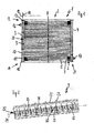
- the Indian FIG. 1 Heat exchangers 1 shown by way of example can be used in motor vehicles, for example, in order to cool coolant of an internal combustion engine (not shown here).
- the heat exchanger 1 comprises a cooler network 2, on which a coolant inlet box 3 and a coolant outlet box 4 are arranged. Between the two coolant boxes 3 and 4 extend coolant tubes 5 (numbered here only by way of example), so that one to cooling coolant can flow from the coolant inlet box 3 to the coolant drainage 4.
- cooling rib shafts 6 are arranged in this embodiment between the individual coolant tubes 5; which extend from the coolant inlet box 3 to the coolant drain box 4.
- Each of the cooling fin shafts 6 provides a plurality of cooling fins 7 on the heat exchanger 1.
- the total leakage area for heat energy of the heat exchanger 1 is advantageously increased, which in turn allows the cooling performance of the heat exchanger 1 can be improved.
- a vertically extending retaining web 8 is provided, by means of which the cooling tubes 5 can be additionally held.
- Both the coolant inlet box 3 and the coolant outlet box 4 are each composed of a bent tube sheet 9 and a bent box part 10 together (numbered here only in terms of the coolant inlet box 3).
- the tube sheet 9 and the box part 10 are pressed liquid-tightly together at a seam 11 and closed at the top 12 with a first closure 13 and at the bottom 14 with a further closure 15.
- the coolant inlet box 3 also has a coolant inlet 16, while thedemitkelablaufkasten 4 has a coolant outlet 17 in the region of the bottom 14.
- the respective bent tube sheet 9 of the coolant inlet box 3 or of the coolant discharge box 4 is arranged relative to the individual coolant tubes 5 such that the coolant tubes 5 are aligned substantially at a right angle 18 to the longitudinal extent 19.
- the passages 20 are arranged along the longitudinal extension 19 at a bottom region of the tube bottom 9.
- the coolant inlet box 3 and the coolant outlet box 4 can generally be referred to as header boxes 21, which are essentially composed of a tube plate 9 and a box part 10, as described by way of example below.
- the Indian FIG. 2 tube sheet 9 shown has at its elongated edges 22 on a plurality of Vorfixierlaschen 23.
- first contact surfaces 26 (here only exemplified), with the second contact surfaces 27 (here only exemplified) of the box part 10 (see FIG. 3 ) Soldering regions 28 of the headers 21 can form.
- the first contact surfaces 26 and the second contact surfaces 27 in a suitable and known manner with solder (not numbered here) be provided.
- the contact-securing means 30 comprise in particular in this exemplary embodiment, therefore, on the one hand, the contact securing pins 29 and, on the other hand, the contact securing hubs 31,
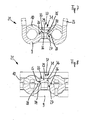
- the contact-securing pins 29 of the tube sheet 9 are advantageously arranged in the Kunststofftechnischsnaben 31 of the box part 10, in such a way that the contact-securing pins 29, the contact securing hubs 31, in the form of the through holes 32, can pierce, as particularly well according to the illustrations of FIGS. 7 and 8 is recognizable.
- the present contact-securing means 30 simultaneously form solder-initiation structures 33, by means of which there is always a contact area 34, even if only a small contact area, between the first contact areas 26 and the second contact areas 27 is trained. This is true even if areas of the first contact surfaces 26 and second contact surfaces 27 are not touching each other.
- contact-securing pins 29 in this embodiment form elevations 35 within the first contact surfaces 26 and the contact-securing hubs 31 depressions 36 within the second contact surfaces 27.
- the means 30 for securing contacts in particular corresponding elevations 35 and depressions 36, are additionally positively connected with one another by pressing the contact securing pins 29 with the contact securing hubs 31, a particularly intimate contact of the first contact surfaces 26 and the second contact surfaces 27 is ensured (see in particular FIGS. 6 to 8 ).
- the means 30 for securing contact sufficiently large contact surfaces 26 and 27 are available for forming the solder regions 28 in particular in the longitudinal partition wall portion 25 of the headers 21, the means 30 for securing each contact by a distance 38 (by way of example only with respect to FIG. 6 located) spaced from each other.
- the means 30 when the means 30 are pressed to secure contact, can alternatively be dispensed with the prefixing tabs 23 still provided here in this embodiment, so that the collecting boxes 21 structurally can be constructed even easier.
Abstract
Description
Die Erfindung betrifft einen Sammelkasten, insbesondere eines Wärmeübertragers eines Kraftfahrzeuges, mit einem Rohrboden umfassend erste Kontaktflächen, mit einem Kastenteil umfassend zweite Kontaktflächen, bei welchem der Rohrboden und das Kastenteil an Lötbereichen miteinander verlötet sind, und bei Welchem die ersten Kontaktflächen und die zweiten Kontaktflächen die Lötbereiche bilden können. Des Weiteren betrifft die Erfindung einen Wärmeübertrager, insbesondere einen Kondensator, eines Kraftfahrzeuges mit einem Wärmeübertragerblock und mit Sammelkästen, bei welchem Kühlrohre des Wärmeübertragerblocks in die Sammelkästen münden.The invention relates to a collecting box, in particular a heat exchanger of a motor vehicle, comprising a tube bottom comprising first contact surfaces, with a box part comprising second contact surfaces, wherein the tube sheet and the box part are soldered together at soldering areas, and at Welchem the first contact surfaces and the second contact surfaces Can form soldering areas. Furthermore, the invention relates to a heat exchanger, in particular a condenser, of a motor vehicle with a heat exchanger block and with collecting boxes, in which cooling tubes of the heat exchanger block open into the collecting boxes.
Gattungsgemäße Sammelkästen für Wärmeübertrager sind aus dem Stand der Technik gut bekannt und bestehen häufig aus wenigstens zwei Formteilen, die miteinander verlötet sind, so dass der Sammelkasten insbesondere flüssigkeitsdicht und druckfest ausgebildet werden kann. Bei den vorgenannten Formteilen handelt es sich in der Regel um einen Rohrboden und ein Kastenteil bzw. einen Deckel des Sammelkastens.Generic headers for heat exchangers are well known in the art and often consist of at least two moldings, which are soldered together, so that the collecting tank can be formed in particular liquid-tight and pressure-resistant. In the aforementioned moldings is usually a tube plate and a box part or a lid of the header tank.
Aus der Offenlegungsschrift
Bei einem anderen Wärmeübertrager aus der Offenlegungsschrift
Aus der Offenlegungsschrift
Es ist Aufgabe vorliegender Erfindung gattungsgemäße Sammelkästen weiter zu entwickeln.It is an object of the present invention to further develop generic collecting tanks.
Die Aufgabe der Erfindung wird von einem Sammelkasten, insbesondere eines Wärmeübertragers eines Kraftfahrzeuges, mit einem Rohrboden umfassend erste Kontaktflächen, mit einem Kastenteil umfassend weitere Kontakflächen gelöst, bei welchem der Rohrboden und das Kastenteil an Lötbereichen miteinander verlötet sind, und bei welchem die ersten Kontaktflächen und die zweiten Kontaktflächen die Lötbereiche bilden können, wobei sich der Sammelkasten durch Mittel zur Kontaktsicherung auszeichnet, mittels welchen in den Lötbereichen ein kritisches Entfernen der Kontaktflächen voneinander verhindert wird.The object of the invention is achieved by a collecting box, in particular a heat exchanger of a motor vehicle, having a tube bottom comprising first contact surfaces, comprising a box part comprising further contact surfaces, wherein the tube plate and the box part are soldered to soldering areas, and in which the first contact surfaces and the second contact surfaces can form the soldering areas, the collecting box being characterized by means for securing the contact, by means of which a critical removal of the contact surfaces from one another is prevented in the soldering areas.
Zwar ist es aus dem Stand der Technik bekannt, miteinander zu verlötende Formteile eines Sammelkastens, wie etwa ein Rohrboden und ein Kastenteil, miteinander vorzufixieren, so dass die beiden Formteile vor dem eigentlichen dauerhaften Zusammenfügen gut handbar sind und die Gefahr eines Auseinanderfallens des vorfixierten Sammelkastens verringert ist. Jedoch kann mittels einer derartigen herkömmlichen Vorfixierung nicht betriebssicher gewährleistet werden, dass die miteinander zu verlötenden Kontaktflächen in den eigentlichen Lötbereichen auch derart eng und gut aneinander liegen, dass sich dort eine qualitativ hochwertige Lötverbindung zwischen den zu verlötenden Formbauteilen des Sammelkastens ausbilden können. Eine nicht optimale Lötverbindung kann drastisch die Festigkeit des Sammelkastens reduzieren, insbesondere die Beständigkeit des Sammelkastens gegenüber hohen Innendrücken, so dass etwa auch der Berstdruck des Sammelkastens wesentlich reduziert ist. Selbst wenn die zu verlötenden Formbauteile des Sammelkastens zuvor während der Vorfixierung aneinander gepresst wurden, kann auf Grund von Fertigungsungenauigkeiten bei der Herstellung der Formbauteile nicht garantiert werden, dass diese an ihren Kontaktflächen immer ausreichend aneinander liegen können. Selbst wenn sie bei der Vorfixierung noch ausreichend aneinander liegen, kann es insbesondere bei einer Erwärmung hinsichtlich eines Lötprozesses dazu kommen, dass sich zwei einen Lötbereich bildende Kontaktflächen kritisch voneinander entfernen, so dass sich dort keine ausreichende Lötverbindung bilden kann.Although it is known from the prior art, prefixed to each other to be soldered moldings of a collecting box, such as a tube sheet and a box part, so that the two moldings are well handleable before the actual permanent assembly and the risk of falling apart of the prefixed header tank is reduced. However, it can not be reliably ensured by means of such conventional prefixing that the contact surfaces to be soldered together in the actual soldering areas are also so close and good that a high quality soldered connection can be formed there between the molded components of the collecting box to be soldered. A non-optimal solder joint can drastically reduce the strength of the header, in particular the resistance of the header to high internal pressures, so that about the bursting pressure of the header is substantially reduced. Even if the molded components of the collecting tank to be soldered were previously pressed against each other during the pre-fixing, it can not be guaranteed due to production inaccuracies in the production of the molded components that they can always lie sufficiently against one another at their contact surfaces. Even if they are still sufficiently adjacent to one another during the pre-fixing, it can happen, in particular in the case of heating with respect to a soldering process, that two contact areas forming a soldering area critically move away from each other so that a sufficient solder joint can not form there.
Mittels der erfindungsgemäßen Mittel zur Kontaktsicherung ist die Gefahr jedoch drastisch verringert, dass sich zwei einen Lötbereich bildende Kontaktflächen kritisch voneinander entfernen. Hierdurch ist gewährleistet, dass der Sammelkasten besonders druckstabil ist. Dies ist besonders im Hinblick auf Kondensatoren vorteilhaft, da bei diesen oftmals Kälteprozesse mit hohen Drücken beherrscht werden müssen.By means of the contact securing means according to the invention, however, the risk is drastically reduced that two contact surfaces forming a soldering area critically remove one another. This ensures that the collecting tank is particularly pressure-stable. This is particularly advantageous in terms of capacitors, since these often cold processes with high pressures must be controlled.
Der Begriff "Kontaktfläche" beschreibt Flächen des Rohrbodens bzw. des Kastenteils, im Allgemeinen also des Sammelkastens, die aneinander liegend Lötbereiche bereitstellen können, in welchen eine Lötverbindung zwischen dem Rohrboden und dem Kastenteil ausgebildet werden sollen.The term "contact surface" describes surfaces of the tube bottom or the box part, generally of the collecting box, which can provide each other soldering areas in which a solder joint between the tube sheet and the box part to be formed.
Der Begriff "Lötbereiche" beschreibt vorliegend diejenigen Bereiche der Kontakflächen, an welchen Formbauteile des Sammelkastens mittels Lötverbindungen miteinander verlötet werden sollen. In diesem Zusammenhang versteht es sich, dass nicht alle Kontaktflächen zwischen den Formbauteilen zwangsläufig Lötbereiche ausbilden müssen.In the present case, the term "soldering areas" describes those areas of the contact surfaces at which molded components of the collecting box are to be soldered to one another by means of soldered connections. In this context, it is understood that not all contact surfaces between the mold components necessarily form soldering areas.
Es versteht sich auch, dass die Mittel zur Kontaktsicherung, nachfolgend auch kurz Kontaktsicherungsmittel genannt, vielfältiger Gestalt sein können, so lange mit ihnen ein außergewöhnlich guter Kontakt zwischen Kontaktflächen der Formbauteile des Sammelkastens sicher gestellt werden können, so dass sich an diesen Kontaktflächen eine Verlötung während eines gemeinsamen Lötprozesses des Sammelkastens besonders gut ausbilden kann. Die Kontaktsicherungsmittel können hierbei an nahezu allen Kontaktflächen vorgesehen sein, die Lötbereiche des Sammelkastens ausbilden sollen.It is also understood that the means for securing contacts, hereinafter also referred to as contact securing means, may be of various shapes, as long as an extraordinarily good contact between contact surfaces of the molded components of the collecting tank can be ensured with them, so that soldering takes place at these contact surfaces a common soldering process of the header box can form particularly well. The contact securing means can be provided here on almost all contact surfaces that are to form soldering areas of the collecting tank.
Eine bevorzugte Ausführungsvariante sieht in diesem Zusammenhang vor, dass die Mittel zur Kontaktsicherung an einem Längstrennwandbereich des Sammelkastens angeordnet sind. Ein solcher Längstrennwandbereich kann den Sammelkasten in zwei Hauptkanäle unterteilen. Insbesondere eignet er sich hierdurch hervorragend zum Platzierten von Kontaktflächen sowohl an dem Rohrboden als auch an dem Kastenteil des Sammelkastens, wobei die Druckbeständigkeit des Sammelkastens besonders hoch sein kann, wenn der Rohrboden und das Kastenteil dort miteinander verlötet sind.In this context, a preferred embodiment variant provides that the means for securing the contact are arranged on a longitudinal dividing wall region of the collecting tank. Such a longitudinal partition wall portion may divide the collecting box into two main channels. In particular, this makes it ideal for placing contact surfaces on both the tube sheet and the box portion of the header tank, with the pressure resistance of the header box being particularly high when the tube sheet and box member are brazed together.
Konstruktiv einfach können die Kontaktsicherungsmittel bereitgestellt werden, wenn die Mittel zu Kontaktsicherung innerhalb der Lötbereiche angeordnet sind. Zwar verkleinert sich hierdurch der jeweilige Lötbereich, jedoch kann dies mit einer der gesamte Lötverbindung für ausgeglichen werden. Insbesondere, wenn nicht der gesamte Lötbereich für die Erfüllung der Festigkeitsanforderungen erforderlich ist.The contact-securing means can be provided in a structurally simple manner if the means for securing the contact are arranged within the soldering areas. Although this reduces the respective soldering area, but this can be compensated with one of the entire solder joint for. In particular, if not the entire soldering area is required to meet the strength requirements.
Die Qualität der Lötverbindungen an den Lötbereichen des Sammelkastens kann weiter erhöht werden, wenn die Mittel zur Kontaktsicherung Lötinitialisierungsgebilde aufweisen. Derartige Lötinitialisierungsgebilde können besonders betriebssicher einen Kontakt zwischen ersten Kontaktflächen und zweiten Kontaktflächen gewährleisten, von denen ausgehend sich eine Lötverbindung ausgezeichnet ausbilden kann.The quality of the solder joints at the soldering areas of the collecting box can be further increased if the means for securing contacts have solder initiation formations. Such Lötinitialisierungsgebilde can ensure particularly reliable contact between the first contact surfaces and second contact surfaces, starting from which a solder joint can form excellent.
In diesem Zusammenhang ist es vorteilhaft, wenn die Mittel zur Kontaktsicherung Erhebungen innerhalb der ersten Kontaktflächen und/oder der zweiten Kontaktflächen aufweisen.In this connection, it is advantageous if the means for securing the contact have elevations within the first contact surfaces and / or the second contact surfaces.
Darüber hinaus ist es vorteilhaft, wenn die Mittel zur Kontaktsicherung Senken innerhalb der ersten Kontaktflächen und/oder der zweiten Kontaktflächen aufweisen.Moreover, it is advantageous for the means for securing the contact to have depressions within the first contact surfaces and / or the second contact surfaces.
Sind Erhebungen der Mittel zur Kontaktsicherung und Senken der Mittel zur Kontaktsicherung formschlüssig miteinander verbunden, können Kontaktflächen an Lötbereichen besonders betriebssicher aneinander liegend gehalten werden.If elevations of the means for securing the contact and lowering the means for securing the contact are positively connected to one another, contact areas on soldering areas can be held in a particularly reliable manner against each other.
In der Praxis hat es sich als vorteilhaft erwiesen, wenn die Mittel zur Kontaktsicherung eine Zapfen-Nabe-Verbindung aufweisen.In practice, it has proven to be advantageous if the means for securing contact a pin-hub connection.
Durchdringen die Mittel zur Kontaktsicherung den Rohrboden oder den Deckel können zusätzlich Pressverbindungen von außen an innenliegenden Lötbereichen hergestellt werden, wodurch eine besonders enge Pressung der ersten und zweiten Kontaktflächen zueinander gewährleistet werden kann.If the means for securing the contact with the tubesheet or the lid penetrate additional pressing connections can be made from outside to inside soldering areas, whereby a particularly close pressure of the first and second contact surfaces can be ensured to each other.
Beispielweise kann in diesem Zusammenhang ein Zapfen eines Rohrbodens in eine Nabe, die etwa als Durchgangsbohrung an einem Kastenteil ausgebildet sein kann, derart eingesteckt werden, dass ein freies Ende des Zapfens von der Außenseite eines Sammelkastens her zugänglich ist, so dass der Zapfen in der Nabe von außen, verpresst werden kann. Insofern kann eine besonders eng anliegende Kontakifixierung erzielt werden.For example, in this connection, a pin of a tube plate can be inserted into a hub, which may be formed as a through hole on a box part, such that a free end of the pin is accessible from the outside of a header, so that the pin in the hub from the outside, can be pressed. In this respect, a particularly close-fitting Kontakifixierung can be achieved.
Sind die Mittel zur Kontaktsicherung entlang einer Längsachse des Sammelkastens zueinander beabstandet angeordnet, können sich zwischen den einzelnen Kontaktsicherungsmitteln an den Kontaktflächen zusätzliche Lötbereiche ausbilden, so dass der Rohrboden und das Kastenteil hinreichend großflächig miteinander verlötet werden können.If the means for securing the contact along a longitudinal axis of the collecting tank are arranged at a distance from each other, additional soldering areas can form on the contact surfaces between the individual contact securing means, so that the tube bottom and the box part can be soldered together over a sufficiently large area.
In diesem Zusammenhang wird die Aufgabe auch von einem Wärmeübertrager, insbesondere von einem Kondensator, eines Kraftfahrzeuges mit einem Wärmeübertragerblock und mit Sammelkästen gelöst, bei welchen Kühlrohre des Wärmeübertragers in die Sammelkästen münden, wobei sich der Wärmeübertrager dadurch auszeichnet, dass er einen Sammelkasten nach einem der hier erläuterten Merkmalskombinationen umfasst.In this context, the object is also achieved by a heat exchanger, in particular by a condenser, a motor vehicle with a heat exchanger block and collecting tanks, in which cooling tubes of the heat exchanger open into the manifolds, wherein the heat exchanger is characterized in that it has a collecting box according to one of here comprises feature combinations described.
Weitere Vorteile, Ziele und Eigenschaften vorliegender Erfindung werden anhand nachfolgender Beschreibung anliegender Zeichnung erläutert, in welcher beispielhaft ein Wärmeübertrager sowie ein Rohrboden und ein Kastenteil eines Sammelkastens des Wärmeübertragers dargestellt sind.Further advantages, objects and characteristics of the present invention will be explained with reference to the following description of the appended drawing, in which an example of a heat exchanger and a tube plate and a box part of a header of the heat exchanger are shown.
Es zeigt
- Figur 1
- schematisch eine Ansicht eines Wärmeübertragers mit seitlich angeordneten Sammelkästen,
- Figur 2
- schematisch eine perspektivische Ansicht eines Rohrbodens mit Mitteln zur Kontaktsicherung in Gestalt von Zapfen im Bereich einer Längstrennwand eines Sammelkastens,
Figur 3- schematisch eine perspektivische Ansicht eines Kastenteils mit Mitteln zur Kontaktsicherung in Gestalt von Durchgangslöchern im Bereich der Längstrennwand eines Sammelkastens,
- Figur 4
- schematisch eine perspektivische Ansicht eines Sammelkastens mit dem Rohrboden aus der
Figur 1 und mit dem Kastenteil aus derFigur 3 - Figur 5
- schematisch eine weitere perspektivische Ansicht des Sammelkastens aus der
Figur 4 mit umgebogenen und fixierten Vorfixierlaschen, - Figur 6
- schematisch nochmals eine perspektivische Ansicht des Sammelkastens aus den
Figuren 4 und 5 mit verpressten Kontaktsicherungsmittel, - Figur 7
- schematisch einen Querschnitt des Sammelkastens aus den
Figuren 4 bis 6 im Bereich verpresster Kontaktsichorungsmittel, und Figur 8- schematisch einen Längsschnitt des Sammelkastens im Bereich verpresster Kontaktsicherungsmittel.
- FIG. 1
- 1 is a schematic view of a heat exchanger with laterally arranged collecting boxes;
- FIG. 2
- 2 is a schematic perspective view of a tube plate with contact securing means in the form of pins in the region of a longitudinal dividing wall of a collecting box;
- FIG. 3
- 1 is a schematic perspective view of a box part with contact securing means in the form of through holes in the region of the longitudinal dividing wall of a collecting box;
- FIG. 4
- schematically a perspective view of a collecting tank with the tube sheet from the
FIG. 1 and with the box part from theFIG. 3 and with additional prefixing tabs, - FIG. 5
- schematically another perspective view of the collecting tank from the
FIG. 4 with bent and fixed prefixing straps, - FIG. 6
- schematically again a perspective view of the collecting tank from the
FIGS. 4 and 5 with pressed contact securing means, - FIG. 7
- schematically a cross section of the collecting tank from the
FIGS. 4 to 6 in the field of compressed contact, and - FIG. 8
- schematically a longitudinal section of the header box in the area pressed contact securing means.
Der in der
Sowohl der Kühlmitteleinlaufkasten 3 als auch der Kühlmittelablaufkasten 4 sind jeweils aus einem gebogenen Rohrboden 9 und einem gebogenen Kastenteil 10 zusammen gesetzt (hier nur hinsichtlich des Kühlmitteleinlaufkastens 3 beziffert).Both the
Der Rohrboden 9 und das Kastenteil 10 sind an einer Naht 11 flüssigkeitsdicht miteinander verpresst und an der Oberseite 12 mit einem ersten Verschluss 13 und an der Unterseite 14 mit einem weiteren Verschluss 15 verschlossen. Im Bereich der Oberseite 12 verfügt der Kühlmitteleinlaufkasten 3 zudem über einen Kühlmittelzulauf 16, während der Kühlmitkelablaufkasten 4 im Bereich der Unterseite 14 einen Kühlmittelablauf 17 aufweist.The
Der jeweilige gebogene Rohrboden 9 des Kühlmitteleinlaufkastens 3 bzw. des Kühlmittelablaufkastens 4 ist gegenüber den einzelnen Kühlmittelrohren 5 derart angeordnet, dass die Kühlmittelrohre 5 im Wesentlichen in einem rechten Winkel 18 zu der Längserstreckung 19 ausrichtet sind.The respective
Während der Kühlmittelzulauf 16 bzw. der Kühlmittelablauf 17 jeweils an dem entsprechenden Kastenteil 10 vorgesehen sind, kommunizieren die Kühlmittelrohre 5 mit dem jeweiligen gebogenen Rohrboden 9 des Kühlmitteleinlaufkastens 3 bzw. des Kühlmittelablaufkastens 4, indem sie Durchzüge 20 des gebogenen Rohrbodens 9 durchstoßen. Die Durchzüge 20 sind entlang der Längserstreckung 19 an einem Bodenbereich des Rohrbodens 9 angeordnet.While the
Der kühlmitteleinlaufkasten 3 und der Kühlmittelablaufkasten 4 können in im Allgemeinen als Sammelkästen 21 bezeichnet werden, die im Wesentlichen jeweils aus einem Rohrboden 9 und einem Kastenteil 10 zusammen gesetzt sind, wie sie im nachfolgenden beispielhaft beschrieben sind.The
Der in der
Entlang seiner Rohrbodenmittelachse 24 erstreckt sich ein Längstrennwandbereich 25 der Sammelkästen 21. In diesem Längstrennwandbereich 25 weist der Rohrboden 9 erste Kontaktflächen 26 (hier nur exemplarisch beziffert) auf, die mit zweiten Kontaktflächen 27 (hier nur exemplarisch beziffert) des Kastenteils 10 (siehe
An jeder der ersten Kontaktflächen 26 des Rohrbodens 9 sind Kontaktsicherungszapfen 29 von Mitteln 30 zur Kontaktsicherung der Sammelkästen 21 angeordnet. Dementsprechend sind die zweiten Kontaktflächen 27 mit Kontaktsicherungsnaben 31 in Form von Durchgangslöchern 32 der Mittel 30 zur Kontaktsicherung ausgestattet. Die Mittel 30 zur Kontaktsicherung umfassen insbesondere in diesem Ausführungsbeispiel also einerseits die Kontaktsicherungszapfen 29 und andererseits die Kontaktsicherungsnaben 31,At each of the first contact surfaces 26 of the
ist das Kastenteil 10 in den Rohrboden 9 gemäß den
Da die Kontaktsicherungszapfen 29 die zweiten Kontaktflächen 27 des Kastenteils 10 durchdringen können, bilden die vorliegenden Mittel 30 zur Kontaktsicherung zugleich Lötinitialisierungsgebilde 33 aus, mittels welchen immer ein Kontaktbereich 34, wenn auch nur ein kleiner Kontaktbereich, zwischen den ersten Kontaktflächen 26 und den zweiten Kontaktflächen 27 ausgebildet ist. Dies trifft selbst dann zu, wenn Bereiche der ersten Kontaktflächen 26 und zweiten Kontaktflächen 27 sich nicht berührend gegenüber liegen.Since the contact-securing
Dies liegt daran, dass die Kontaktsicherungszapfen 29 in diesem Ausführungsbeispiel Erhebungen 35 innerhalb der ersten Kontaktflächen 26 und die Kontaktsicherungsnaben 31 Senken 36 innerhalb der zweiten Kontaktflächen 27 bilden.This is because the contact-securing
Allein dieses Anordnen der Erhebungen 35 und Senken 36 zueinander bedingt bereits eine sehr gute Kontaktsicherung der ersten Kontaktflächen 26 und der zweiten Kontaktflächen 27 zueinander, so dass sich in den Lötbereichen 28 betriebssicher immer sehr gute Lötverbindungen ausbilden können, wodurch wiederum die Sammelkästen 21 insgesamt sehr druckstabil sind und sich darüber hinaus durch einen hohen Berstdruck auszeichnen.Alone, this arranging the
Werden die Mittel 30 zur Kontaktsicherung insbesondere diesbezüglicher Erhebungen 35 und Senken 36 zusätzlich formschlüssig miteinander verbunden, indem die Kontaktsicherungszapfen 29 mit den Kontaktsicherungsnaben 31 verpresst werden, ist eine besonders innige Berührung der ersten Kontaktflächen 26 und der zweiten Kontaktflächen 27 gewährleistet (siehe insbesondere
Hierbei sind auch verpresste und damit besonders feste Zapfen-Nabe-Verbindungen 37 mittels der Mittel 30 zur Kontaktsicherung an den Sammelkästen 21 bereitgestellt.In this case, also pressed and thus particularly strong pin-
Damit insbesondere im Längstrennwandbereich 25 der Sammelkästen 21 trotz der Mittel 30 zur Kontaktsicherung genügend große Kontaktflächen 26 und 27 zum Ausbilden der Lotbereiche 28 zur Verfügung stehen, sind die Mittel 30 zur Kontaktsicherung jeweils um einen Abstand 38 (exemplarisch nur hinsichtlich der
Speziell wenn die Mittel 30 zur Kontaktsicherung verpresst werden, kann alternativ auf die hier bei diesem Ausführungsbeispiel noch vorgesehenen Vorfixierlaschen 23 verzichtet werden, so dass die Sammelkästen 21 baulich noch einfacher konstruiert werden können.Specifically, when the
- 11
- WärmeübertragerHeat exchanger
- 22
- Kühlernetzradiator core
- 33
- KühlwassereinlaufkastenCooling water inlet box
- 44
- KühlwasserablaufkastenCooling water drain box
- 55
- KühlwasserrohreCooling water pipes
- 66
- KühlrippenwellenFins waves
- 77
- Kühlrippencooling fins
- 88th
- Haltestegholding web
- 99
- Rohrbodentube sheet
- 1010
- Kastenteilbox part
- 1111
- Nahtseam
- 1212
- Oberseitetop
- 1313
- erster Verschlussfirst closure
- 1414
- Unterseitebottom
- 1515
- weiterer Verschlussanother closure
- 1616
- KühlwasserzulaufCooling water inlet
- 1717
- KühlwasserablaufCooling water outlet
- 1818
- rechter Winkelright angle
- 1919
- Längserstreckunglongitudinal extension
- 2020
- Durchzügeby trains
- 2121
- Sammelkästencollection boxes
- 2222
- längliche Ränderelongated edges
- 2323
- VorfixierlaschenVorfixierlaschen
- 2424
- Mittelachsecentral axis
- 2525
- LängstrennwandbereichLongitudinal partition area
- 2626
- erste Kontaktflächenfirst contact surfaces
- 2727
- zweite Kontaktflächensecond contact surfaces
- 2828
- Lötbereichensolder bumps
- 2929
- KontaktsicherungszapfenContact security bolts
- 3030
- Mittel zur KontaktsicherungMeans for contact security
- 3131
- KontaktsicherungsnabenContact securement hubs
- 3232
- DurchgangslöcherThrough holes
- 3333
- LötinitialisierungsgebildeLötinitialisierungsgebilde
- 3434
- Kontaktbereichecontact areas
- 3535
- Erhebungensurveys
- 3636
- SenkenReduce
- 3737
- Zapfen-Nabe-VerbindungPin-hub connection
- 3838
- Abstanddistance
Claims (12)
dadurch gekennzeichnet, dass die Mittel (30) zur Kontaktsicherung Lötinitialisierungsgebilde (33) aufweisen.Collecting box (3, 4, 21) according to one of the preceding claims,
characterized in that the means (30) for securing contacts Lötinitialisierungsgebilde (33).
dadurch gekennzeichnet, dass die Mittel (30) zur Kontaktsicherung Erhebungen (35) innerhalb der ersten Kontaktflächen (26) und/oder der zweiten Kontaktflächen (27) aufweisen.Collecting box (3, 4, 21) according to one of the preceding claims,
characterized in that the means (30) for securing contact elevations (35) within the first contact surfaces (26) and / or the second contact surfaces (27).
dadurch gekennzeichnet, dass die Mittel zur Kontaktsicherung Senken (36) innerhalb der ersten Kontaktflächen (26) und/oder der zweiten Kontaktflächen (27) aufweisen.Collecting box (3, 4, 21) according to one of the preceding claims,
characterized in that the means for securing contact depressions (36) within the first contact surfaces (26) and / or the second contact surfaces (27).
dadurch gekennzeichnet dass Erhebungen (35) der Mittel (30) zur Kontaktsicherung und Senken (36) der Mittel (30) zur Kontaktsicherung formschlüssig miteinander verbunden sind.Collecting box (3, 4, 21) according to one of the preceding claims,
characterized in that elevations (35) of the means (30) for securing contact and depressions (36) of the means (30) for securing contact are positively connected to one another.
dadurch gekennzeichnet dass die Mittel (30) zur Kontaktsicherung eine Zapfen-Nabe-Verbindung (37) aufweisen.Collecting box (3, 4, 21) according to one of the preceding claims,
characterized in that the means (30) for securing contact a pin-hub connection (37).
dadurch gekennzeichnet, dass die Mittel (30) zur Kontaktsicherung den Rohrboden (9) oder das Kastenteil (10) durchdringen.Collecting box (3, 4, 21) according to one of the preceding claims,
characterized in that the means (30) for contact securing the tube plate (9) or the box part (10) penetrate.
dadurch gekennzeichnet, dass die Mittel (30) zur Kontaktsicherung entlang einer Längsachse (24) des Sammelkastens (21) zueinander beabstandet angeordnet sind.Collecting box (3, 4, 21) according to one of the preceding claims,
characterized in that the means (30) for securing contact along a longitudinal axis (24) of the collecting tank (21) are arranged spaced from each other.
dadurch gekennzeichnet dass der Rohrboden (9) und/oder das Kastenteil (10) Mittel (23) zur Vorfixierung aufweisen.Collecting box (3, 4, 21) according to one of the preceding claims,
characterized in that the tube plate (9) and / or the box part (10) have means (23) for prefixing.
Applications Claiming Priority (1)
| Application Number | Priority Date | Filing Date | Title |
|---|---|---|---|
| DE102008029420A DE102008029420A1 (en) | 2008-06-23 | 2008-06-23 | Collection box, in particular a heat exchanger of a motor vehicle, and heat exchanger, insbesondere capacitor, a motor vehicle |
Publications (3)
| Publication Number | Publication Date |
|---|---|
| EP2138798A2 true EP2138798A2 (en) | 2009-12-30 |
| EP2138798A3 EP2138798A3 (en) | 2013-08-21 |
| EP2138798B1 EP2138798B1 (en) | 2017-07-19 |
Family
ID=41100869
Family Applications (1)
| Application Number | Title | Priority Date | Filing Date |
|---|---|---|---|
| EP09008186.0A Not-in-force EP2138798B1 (en) | 2008-06-23 | 2009-06-23 | Header box, in particular of a heat exchanger for automotive vehicle and heat exchanger, more particularly condenser for automotive vehicle |
Country Status (2)
| Country | Link |
|---|---|
| EP (1) | EP2138798B1 (en) |
| DE (1) | DE102008029420A1 (en) |
Families Citing this family (2)
| Publication number | Priority date | Publication date | Assignee | Title |
|---|---|---|---|---|
| DE102012002234A1 (en) | 2012-02-04 | 2013-08-08 | Volkswagen Aktiengesellschaft | Heat exchanger, particularly radiator for vehicle, has multiple fins oriented perpendicular to tubing, where adjacent fins surround intermediate space by spacers, and sections of web or spacer are formed on base side or on mold side of fin |
| DE102013021733A1 (en) * | 2013-12-20 | 2015-06-25 | Jürgen Servay | Cooler for pressurized gases |
Citations (3)
| Publication number | Priority date | Publication date | Assignee | Title |
|---|---|---|---|---|
| US20030159813A1 (en) | 2002-02-28 | 2003-08-28 | Norsk Hydro | Heat exchanger manifold and method of assembly |
| DE10315371A1 (en) | 2003-04-03 | 2004-10-14 | Behr Gmbh & Co. Kg | Heat exchanger |
| DE102004037688A1 (en) | 2003-08-05 | 2005-05-25 | Behr Gmbh & Co. Kg | Heat exchanger for use in road vehicle has collection or distribution manifold with two molded parts fitted together to form two flow channels side-by-side with openings for ends of heat exchanger tubes |
Family Cites Families (5)
| Publication number | Priority date | Publication date | Assignee | Title |
|---|---|---|---|---|
| US5366008A (en) * | 1993-08-16 | 1994-11-22 | General Motors Corporation | Method of manufacturing header condensers |
| US6216776B1 (en) * | 1998-02-16 | 2001-04-17 | Denso Corporation | Heat exchanger |
| US6745827B2 (en) * | 2001-09-29 | 2004-06-08 | Halla Climate Control Corporation | Heat exchanger |
| AU2003274761A1 (en) * | 2002-10-30 | 2004-05-25 | Showa Denko K.K. | Heat exchanger, heat exchanger tube member, heat exchanger fin member and process for fabricating the heat exchanger |
| JP4898672B2 (en) * | 2005-06-01 | 2012-03-21 | 昭和電工株式会社 | Heat exchanger |
-
2008
- 2008-06-23 DE DE102008029420A patent/DE102008029420A1/en not_active Withdrawn
-
2009
- 2009-06-23 EP EP09008186.0A patent/EP2138798B1/en not_active Not-in-force
Patent Citations (3)
| Publication number | Priority date | Publication date | Assignee | Title |
|---|---|---|---|---|
| US20030159813A1 (en) | 2002-02-28 | 2003-08-28 | Norsk Hydro | Heat exchanger manifold and method of assembly |
| DE10315371A1 (en) | 2003-04-03 | 2004-10-14 | Behr Gmbh & Co. Kg | Heat exchanger |
| DE102004037688A1 (en) | 2003-08-05 | 2005-05-25 | Behr Gmbh & Co. Kg | Heat exchanger for use in road vehicle has collection or distribution manifold with two molded parts fitted together to form two flow channels side-by-side with openings for ends of heat exchanger tubes |
Also Published As
| Publication number | Publication date |
|---|---|
| EP2138798B1 (en) | 2017-07-19 |
| DE102008029420A1 (en) | 2009-12-24 |
| EP2138798A3 (en) | 2013-08-21 |
Similar Documents
| Publication | Publication Date | Title |
|---|---|---|
| EP1995544B1 (en) | Heat exchanger, in particular charger air cooler or exhaust gas cooler for a combustion engine of a motor vehicle and manufacturing method therefor | |
| EP2044304B1 (en) | Heat exchanger with coupling connection, for example charge air cooler, and coupling connection for heat exchanger | |
| EP1724536B1 (en) | Heat exchanger with accumulator | |
| EP1929233B1 (en) | Charge-air cooler or exhaust gas cooler for an internal combustion engine of a motor vehicle | |
| DE3720483A1 (en) | Heat exchanger | |
| DE10136861A1 (en) | Air-cooled intercooler | |
| DE102007028792A1 (en) | heat exchangers | |
| DE4305060C2 (en) | Soldered heat exchanger, especially evaporator | |
| DE112019003711T5 (en) | Integrated liquid / air cooled condenser and low temperature cooler | |
| DE102006043526A1 (en) | Heat exchanger e.g. intercooler or exhaust gas cooler, for internal combustion engine of motor vehicle, has tank comprising cover and base, where base is provided with passage openings and groove into which wall section of cover extends | |
| DE102004002252B4 (en) | Heat exchanger for vehicles | |
| EP1500892A2 (en) | Heat exchanger for vehicles | |
| DE102006002932A1 (en) | Heat exchanger tube has internal chamber extends from center of tube past location to interior surface of second narrow side | |
| EP2438384A2 (en) | Header for a condenser | |
| DE19961199B4 (en) | The heat exchanger | |
| DE10158387A1 (en) | Heat exchanger for evaporative cooling of electronic/electric components has a pressure-tight container for surrounding the components in a bath of electrically insulating evaporative liquid. | |
| DE102004007510B4 (en) | Heat exchangers, in particular oil coolers for motor vehicles | |
| EP1771697B1 (en) | Heat exchanger, box for receiving a fluid for a heat exchanger, and method for the production of such a box | |
| DE60126381T2 (en) | Heat exchange module, in particular for motor vehicles, and method for its use | |
| EP2138798B1 (en) | Header box, in particular of a heat exchanger for automotive vehicle and heat exchanger, more particularly condenser for automotive vehicle | |
| DE602004004155T2 (en) | HEAT EXCHANGER WITH IMPROVED TRENCH WALL | |
| EP2167895B1 (en) | Heat exchanger | |
| DE19746371A1 (en) | Heat exchanger with twin=chamber collection box | |
| DE19830846A1 (en) | Heat exchanger for IC engine, has stacked flat profile tubes between collector boxes and with space between tubes used for separate coolant circuit | |
| EP2994712B1 (en) | Heat exchanger |
Legal Events
| Date | Code | Title | Description |
|---|---|---|---|
| PUAI | Public reference made under article 153(3) epc to a published international application that has entered the european phase |
Free format text: ORIGINAL CODE: 0009012 |
|
| AK | Designated contracting states |
Kind code of ref document: A2 Designated state(s): AT BE BG CH CY CZ DE DK EE ES FI FR GB GR HR HU IE IS IT LI LT LU LV MC MK MT NL NO PL PT RO SE SI SK TR |
|
| PUAL | Search report despatched |
Free format text: ORIGINAL CODE: 0009013 |
|
| AK | Designated contracting states |
Kind code of ref document: A3 Designated state(s): AT BE BG CH CY CZ DE DK EE ES FI FR GB GR HR HU IE IS IT LI LT LU LV MC MK MT NL NO PL PT RO SE SI SK TR |
|
| AX | Request for extension of the european patent |
Extension state: AL BA RS |
|
| RIC1 | Information provided on ipc code assigned before grant |
Ipc: F28F 9/02 20060101AFI20130718BHEP |
|
| 17P | Request for examination filed |
Effective date: 20140221 |
|
| RBV | Designated contracting states (corrected) |
Designated state(s): AT BE BG CH CY CZ DE DK EE ES FI FR GB GR HR HU IE IS IT LI LT LU LV MC MK MT NL NO PL PT RO SE SI SK TR |
|
| 17Q | First examination report despatched |
Effective date: 20140523 |
|
| RAP1 | Party data changed (applicant data changed or rights of an application transferred) |
Owner name: MAHLE BEHR GMBH & CO. KG |
|
| GRAP | Despatch of communication of intention to grant a patent |
Free format text: ORIGINAL CODE: EPIDOSNIGR1 |
|
| INTG | Intention to grant announced |
Effective date: 20160830 |
|
| GRAS | Grant fee paid |
Free format text: ORIGINAL CODE: EPIDOSNIGR3 |
|
| GRAJ | Information related to disapproval of communication of intention to grant by the applicant or resumption of examination proceedings by the epo deleted |
Free format text: ORIGINAL CODE: EPIDOSDIGR1 |
|
| GRAL | Information related to payment of fee for publishing/printing deleted |
Free format text: ORIGINAL CODE: EPIDOSDIGR3 |
|
| INTC | Intention to grant announced (deleted) | ||
| GRAP | Despatch of communication of intention to grant a patent |
Free format text: ORIGINAL CODE: EPIDOSNIGR1 |
|
| INTG | Intention to grant announced |
Effective date: 20170118 |
|
| GRAJ | Information related to disapproval of communication of intention to grant by the applicant or resumption of examination proceedings by the epo deleted |
Free format text: ORIGINAL CODE: EPIDOSDIGR1 |
|
| GRAL | Information related to payment of fee for publishing/printing deleted |
Free format text: ORIGINAL CODE: EPIDOSDIGR3 |
|
| GRAP | Despatch of communication of intention to grant a patent |
Free format text: ORIGINAL CODE: EPIDOSNIGR1 |
|
| INTC | Intention to grant announced (deleted) | ||
| INTG | Intention to grant announced |
Effective date: 20170327 |
|
| GRAA | (expected) grant |
Free format text: ORIGINAL CODE: 0009210 |
|
| AK | Designated contracting states |
Kind code of ref document: B1 Designated state(s): AT BE BG CH CY CZ DE DK EE ES FI FR GB GR HR HU IE IS IT LI LT LU LV MC MK MT NL NO PL PT RO SE SI SK TR |
|
| REG | Reference to a national code |
Ref country code: GB Ref legal event code: FG4D Free format text: NOT ENGLISH |
|
| REG | Reference to a national code |
Ref country code: CH Ref legal event code: EP |
|
| REG | Reference to a national code |
Ref country code: IE Ref legal event code: FG4D Free format text: LANGUAGE OF EP DOCUMENT: GERMAN |
|
| REG | Reference to a national code |
Ref country code: AT Ref legal event code: REF Ref document number: 910796 Country of ref document: AT Kind code of ref document: T Effective date: 20170815 |
|
| REG | Reference to a national code |
Ref country code: DE Ref legal event code: R096 Ref document number: 502009014161 Country of ref document: DE |
|
| REG | Reference to a national code |
Ref country code: NL Ref legal event code: MP Effective date: 20170719 |
|
| REG | Reference to a national code |
Ref country code: LT Ref legal event code: MG4D |
|
| PG25 | Lapsed in a contracting state [announced via postgrant information from national office to epo] |
Ref country code: FI Free format text: LAPSE BECAUSE OF FAILURE TO SUBMIT A TRANSLATION OF THE DESCRIPTION OR TO PAY THE FEE WITHIN THE PRESCRIBED TIME-LIMIT Effective date: 20170719 Ref country code: NO Free format text: LAPSE BECAUSE OF FAILURE TO SUBMIT A TRANSLATION OF THE DESCRIPTION OR TO PAY THE FEE WITHIN THE PRESCRIBED TIME-LIMIT Effective date: 20171019 Ref country code: NL Free format text: LAPSE BECAUSE OF FAILURE TO SUBMIT A TRANSLATION OF THE DESCRIPTION OR TO PAY THE FEE WITHIN THE PRESCRIBED TIME-LIMIT Effective date: 20170719 Ref country code: HR Free format text: LAPSE BECAUSE OF FAILURE TO SUBMIT A TRANSLATION OF THE DESCRIPTION OR TO PAY THE FEE WITHIN THE PRESCRIBED TIME-LIMIT Effective date: 20170719 Ref country code: LT Free format text: LAPSE BECAUSE OF FAILURE TO SUBMIT A TRANSLATION OF THE DESCRIPTION OR TO PAY THE FEE WITHIN THE PRESCRIBED TIME-LIMIT Effective date: 20170719 Ref country code: SE Free format text: LAPSE BECAUSE OF FAILURE TO SUBMIT A TRANSLATION OF THE DESCRIPTION OR TO PAY THE FEE WITHIN THE PRESCRIBED TIME-LIMIT Effective date: 20170719 |
|
| PG25 | Lapsed in a contracting state [announced via postgrant information from national office to epo] |
Ref country code: IS Free format text: LAPSE BECAUSE OF FAILURE TO SUBMIT A TRANSLATION OF THE DESCRIPTION OR TO PAY THE FEE WITHIN THE PRESCRIBED TIME-LIMIT Effective date: 20171119 Ref country code: ES Free format text: LAPSE BECAUSE OF FAILURE TO SUBMIT A TRANSLATION OF THE DESCRIPTION OR TO PAY THE FEE WITHIN THE PRESCRIBED TIME-LIMIT Effective date: 20170719 Ref country code: BG Free format text: LAPSE BECAUSE OF FAILURE TO SUBMIT A TRANSLATION OF THE DESCRIPTION OR TO PAY THE FEE WITHIN THE PRESCRIBED TIME-LIMIT Effective date: 20171019 Ref country code: LV Free format text: LAPSE BECAUSE OF FAILURE TO SUBMIT A TRANSLATION OF THE DESCRIPTION OR TO PAY THE FEE WITHIN THE PRESCRIBED TIME-LIMIT Effective date: 20170719 Ref country code: PL Free format text: LAPSE BECAUSE OF FAILURE TO SUBMIT A TRANSLATION OF THE DESCRIPTION OR TO PAY THE FEE WITHIN THE PRESCRIBED TIME-LIMIT Effective date: 20170719 Ref country code: GR Free format text: LAPSE BECAUSE OF FAILURE TO SUBMIT A TRANSLATION OF THE DESCRIPTION OR TO PAY THE FEE WITHIN THE PRESCRIBED TIME-LIMIT Effective date: 20171020 |
|
| REG | Reference to a national code |
Ref country code: DE Ref legal event code: R097 Ref document number: 502009014161 Country of ref document: DE |
|
| PG25 | Lapsed in a contracting state [announced via postgrant information from national office to epo] |
Ref country code: CZ Free format text: LAPSE BECAUSE OF FAILURE TO SUBMIT A TRANSLATION OF THE DESCRIPTION OR TO PAY THE FEE WITHIN THE PRESCRIBED TIME-LIMIT Effective date: 20170719 Ref country code: RO Free format text: LAPSE BECAUSE OF FAILURE TO SUBMIT A TRANSLATION OF THE DESCRIPTION OR TO PAY THE FEE WITHIN THE PRESCRIBED TIME-LIMIT Effective date: 20170719 Ref country code: DK Free format text: LAPSE BECAUSE OF FAILURE TO SUBMIT A TRANSLATION OF THE DESCRIPTION OR TO PAY THE FEE WITHIN THE PRESCRIBED TIME-LIMIT Effective date: 20170719 |
|
| PLBE | No opposition filed within time limit |
Free format text: ORIGINAL CODE: 0009261 |
|
| STAA | Information on the status of an ep patent application or granted ep patent |
Free format text: STATUS: NO OPPOSITION FILED WITHIN TIME LIMIT |
|
| PG25 | Lapsed in a contracting state [announced via postgrant information from national office to epo] |
Ref country code: IT Free format text: LAPSE BECAUSE OF FAILURE TO SUBMIT A TRANSLATION OF THE DESCRIPTION OR TO PAY THE FEE WITHIN THE PRESCRIBED TIME-LIMIT Effective date: 20170719 Ref country code: SK Free format text: LAPSE BECAUSE OF FAILURE TO SUBMIT A TRANSLATION OF THE DESCRIPTION OR TO PAY THE FEE WITHIN THE PRESCRIBED TIME-LIMIT Effective date: 20170719 Ref country code: EE Free format text: LAPSE BECAUSE OF FAILURE TO SUBMIT A TRANSLATION OF THE DESCRIPTION OR TO PAY THE FEE WITHIN THE PRESCRIBED TIME-LIMIT Effective date: 20170719 |
|
| REG | Reference to a national code |
Ref country code: FR Ref legal event code: PLFP Year of fee payment: 10 |
|
| 26N | No opposition filed |
Effective date: 20180420 |
|
| PG25 | Lapsed in a contracting state [announced via postgrant information from national office to epo] |
Ref country code: SI Free format text: LAPSE BECAUSE OF FAILURE TO SUBMIT A TRANSLATION OF THE DESCRIPTION OR TO PAY THE FEE WITHIN THE PRESCRIBED TIME-LIMIT Effective date: 20170719 |
|
| PG25 | Lapsed in a contracting state [announced via postgrant information from national office to epo] |
Ref country code: MT Free format text: LAPSE BECAUSE OF FAILURE TO SUBMIT A TRANSLATION OF THE DESCRIPTION OR TO PAY THE FEE WITHIN THE PRESCRIBED TIME-LIMIT Effective date: 20170719 |
|
| REG | Reference to a national code |
Ref country code: CH Ref legal event code: PL |
|
| GBPC | Gb: european patent ceased through non-payment of renewal fee |
Effective date: 20180623 |
|
| REG | Reference to a national code |
Ref country code: BE Ref legal event code: MM Effective date: 20180630 |
|
| REG | Reference to a national code |
Ref country code: IE Ref legal event code: MM4A |
|
| PG25 | Lapsed in a contracting state [announced via postgrant information from national office to epo] |
Ref country code: LU Free format text: LAPSE BECAUSE OF NON-PAYMENT OF DUE FEES Effective date: 20180623 Ref country code: MC Free format text: LAPSE BECAUSE OF FAILURE TO SUBMIT A TRANSLATION OF THE DESCRIPTION OR TO PAY THE FEE WITHIN THE PRESCRIBED TIME-LIMIT Effective date: 20170719 |
|
| PG25 | Lapsed in a contracting state [announced via postgrant information from national office to epo] |
Ref country code: GB Free format text: LAPSE BECAUSE OF NON-PAYMENT OF DUE FEES Effective date: 20180623 Ref country code: IE Free format text: LAPSE BECAUSE OF NON-PAYMENT OF DUE FEES Effective date: 20180623 Ref country code: LI Free format text: LAPSE BECAUSE OF NON-PAYMENT OF DUE FEES Effective date: 20180630 Ref country code: CH Free format text: LAPSE BECAUSE OF NON-PAYMENT OF DUE FEES Effective date: 20180630 |
|
| PG25 | Lapsed in a contracting state [announced via postgrant information from national office to epo] |
Ref country code: BE Free format text: LAPSE BECAUSE OF NON-PAYMENT OF DUE FEES Effective date: 20180630 |
|
| REG | Reference to a national code |
Ref country code: AT Ref legal event code: MM01 Ref document number: 910796 Country of ref document: AT Kind code of ref document: T Effective date: 20180623 |
|
| PG25 | Lapsed in a contracting state [announced via postgrant information from national office to epo] |
Ref country code: AT Free format text: LAPSE BECAUSE OF NON-PAYMENT OF DUE FEES Effective date: 20180623 |
|
| PG25 | Lapsed in a contracting state [announced via postgrant information from national office to epo] |
Ref country code: TR Free format text: LAPSE BECAUSE OF FAILURE TO SUBMIT A TRANSLATION OF THE DESCRIPTION OR TO PAY THE FEE WITHIN THE PRESCRIBED TIME-LIMIT Effective date: 20170719 |
|
| PG25 | Lapsed in a contracting state [announced via postgrant information from national office to epo] |
Ref country code: PT Free format text: LAPSE BECAUSE OF FAILURE TO SUBMIT A TRANSLATION OF THE DESCRIPTION OR TO PAY THE FEE WITHIN THE PRESCRIBED TIME-LIMIT Effective date: 20170719 Ref country code: HU Free format text: LAPSE BECAUSE OF FAILURE TO SUBMIT A TRANSLATION OF THE DESCRIPTION OR TO PAY THE FEE WITHIN THE PRESCRIBED TIME-LIMIT; INVALID AB INITIO Effective date: 20090623 |
|
| PG25 | Lapsed in a contracting state [announced via postgrant information from national office to epo] |
Ref country code: CY Free format text: LAPSE BECAUSE OF FAILURE TO SUBMIT A TRANSLATION OF THE DESCRIPTION OR TO PAY THE FEE WITHIN THE PRESCRIBED TIME-LIMIT Effective date: 20170719 Ref country code: MK Free format text: LAPSE BECAUSE OF NON-PAYMENT OF DUE FEES Effective date: 20170719 |
|
| PGFP | Annual fee paid to national office [announced via postgrant information from national office to epo] |
Ref country code: FR Payment date: 20200620 Year of fee payment: 12 |
|
| PGFP | Annual fee paid to national office [announced via postgrant information from national office to epo] |
Ref country code: DE Payment date: 20200831 Year of fee payment: 12 |
|
| REG | Reference to a national code |
Ref country code: DE Ref legal event code: R119 Ref document number: 502009014161 Country of ref document: DE |
|
| PG25 | Lapsed in a contracting state [announced via postgrant information from national office to epo] |
Ref country code: DE Free format text: LAPSE BECAUSE OF NON-PAYMENT OF DUE FEES Effective date: 20220101 |
|
| PG25 | Lapsed in a contracting state [announced via postgrant information from national office to epo] |
Ref country code: FR Free format text: LAPSE BECAUSE OF NON-PAYMENT OF DUE FEES Effective date: 20210630 |