EP1995544B1 - Heat exchanger, in particular charger air cooler or exhaust gas cooler for a combustion engine of a motor vehicle and manufacturing method therefor - Google Patents
Heat exchanger, in particular charger air cooler or exhaust gas cooler for a combustion engine of a motor vehicle and manufacturing method therefor Download PDFInfo
- Publication number
- EP1995544B1 EP1995544B1 EP08008752.1A EP08008752A EP1995544B1 EP 1995544 B1 EP1995544 B1 EP 1995544B1 EP 08008752 A EP08008752 A EP 08008752A EP 1995544 B1 EP1995544 B1 EP 1995544B1
- Authority
- EP
- European Patent Office
- Prior art keywords
- base
- box
- heat exchanger
- cover
- exchanger according
- Prior art date
- Legal status (The legal status is an assumption and is not a legal conclusion. Google has not performed a legal analysis and makes no representation as to the accuracy of the status listed.)
- Expired - Fee Related
Links
Images


Classifications
-
- F—MECHANICAL ENGINEERING; LIGHTING; HEATING; WEAPONS; BLASTING
- F28—HEAT EXCHANGE IN GENERAL
- F28F—DETAILS OF HEAT-EXCHANGE AND HEAT-TRANSFER APPARATUS, OF GENERAL APPLICATION
- F28F9/00—Casings; Header boxes; Auxiliary supports for elements; Auxiliary members within casings
- F28F9/02—Header boxes; End plates
- F28F9/0219—Arrangements for sealing end plates into casing or header box; Header box sub-elements
- F28F9/0224—Header boxes formed by sealing end plates into covers
-
- F—MECHANICAL ENGINEERING; LIGHTING; HEATING; WEAPONS; BLASTING
- F02—COMBUSTION ENGINES; HOT-GAS OR COMBUSTION-PRODUCT ENGINE PLANTS
- F02B—INTERNAL-COMBUSTION PISTON ENGINES; COMBUSTION ENGINES IN GENERAL
- F02B29/00—Engines characterised by provision for charging or scavenging not provided for in groups F02B25/00, F02B27/00 or F02B33/00 - F02B39/00; Details thereof
- F02B29/04—Cooling of air intake supply
- F02B29/045—Constructional details of the heat exchangers, e.g. pipes, plates, ribs, insulation, materials, or manufacturing and assembly
- F02B29/0462—Liquid cooled heat exchangers
-
- F—MECHANICAL ENGINEERING; LIGHTING; HEATING; WEAPONS; BLASTING
- F02—COMBUSTION ENGINES; HOT-GAS OR COMBUSTION-PRODUCT ENGINE PLANTS
- F02M—SUPPLYING COMBUSTION ENGINES IN GENERAL WITH COMBUSTIBLE MIXTURES OR CONSTITUENTS THEREOF
- F02M26/00—Engine-pertinent apparatus for adding exhaust gases to combustion-air, main fuel or fuel-air mixture, e.g. by exhaust gas recirculation [EGR] systems
- F02M26/13—Arrangement or layout of EGR passages, e.g. in relation to specific engine parts or for incorporation of accessories
- F02M26/22—Arrangement or layout of EGR passages, e.g. in relation to specific engine parts or for incorporation of accessories with coolers in the recirculation passage
- F02M26/29—Constructional details of the coolers, e.g. pipes, plates, ribs, insulation or materials
- F02M26/32—Liquid-cooled heat exchangers
-
- F—MECHANICAL ENGINEERING; LIGHTING; HEATING; WEAPONS; BLASTING
- F28—HEAT EXCHANGE IN GENERAL
- F28D—HEAT-EXCHANGE APPARATUS, NOT PROVIDED FOR IN ANOTHER SUBCLASS, IN WHICH THE HEAT-EXCHANGE MEDIA DO NOT COME INTO DIRECT CONTACT
- F28D21/00—Heat-exchange apparatus not covered by any of the groups F28D1/00 - F28D20/00
- F28D21/0001—Recuperative heat exchangers
- F28D21/0003—Recuperative heat exchangers the heat being recuperated from exhaust gases
-
- F—MECHANICAL ENGINEERING; LIGHTING; HEATING; WEAPONS; BLASTING
- F28—HEAT EXCHANGE IN GENERAL
- F28D—HEAT-EXCHANGE APPARATUS, NOT PROVIDED FOR IN ANOTHER SUBCLASS, IN WHICH THE HEAT-EXCHANGE MEDIA DO NOT COME INTO DIRECT CONTACT
- F28D7/00—Heat-exchange apparatus having stationary tubular conduit assemblies for both heat-exchange media, the media being in contact with different sides of a conduit wall
- F28D7/16—Heat-exchange apparatus having stationary tubular conduit assemblies for both heat-exchange media, the media being in contact with different sides of a conduit wall the conduits being arranged in parallel spaced relation
- F28D7/1684—Heat-exchange apparatus having stationary tubular conduit assemblies for both heat-exchange media, the media being in contact with different sides of a conduit wall the conduits being arranged in parallel spaced relation the conduits having a non-circular cross-section
-
- F—MECHANICAL ENGINEERING; LIGHTING; HEATING; WEAPONS; BLASTING
- F28—HEAT EXCHANGE IN GENERAL
- F28F—DETAILS OF HEAT-EXCHANGE AND HEAT-TRANSFER APPARATUS, OF GENERAL APPLICATION
- F28F9/00—Casings; Header boxes; Auxiliary supports for elements; Auxiliary members within casings
- F28F9/02—Header boxes; End plates
-
- F—MECHANICAL ENGINEERING; LIGHTING; HEATING; WEAPONS; BLASTING
- F28—HEAT EXCHANGE IN GENERAL
- F28D—HEAT-EXCHANGE APPARATUS, NOT PROVIDED FOR IN ANOTHER SUBCLASS, IN WHICH THE HEAT-EXCHANGE MEDIA DO NOT COME INTO DIRECT CONTACT
- F28D21/00—Heat-exchange apparatus not covered by any of the groups F28D1/00 - F28D20/00
- F28D2021/0019—Other heat exchangers for particular applications; Heat exchange systems not otherwise provided for
- F28D2021/008—Other heat exchangers for particular applications; Heat exchange systems not otherwise provided for for vehicles
- F28D2021/0082—Charged air coolers
-
- Y—GENERAL TAGGING OF NEW TECHNOLOGICAL DEVELOPMENTS; GENERAL TAGGING OF CROSS-SECTIONAL TECHNOLOGIES SPANNING OVER SEVERAL SECTIONS OF THE IPC; TECHNICAL SUBJECTS COVERED BY FORMER USPC CROSS-REFERENCE ART COLLECTIONS [XRACs] AND DIGESTS
- Y02—TECHNOLOGIES OR APPLICATIONS FOR MITIGATION OR ADAPTATION AGAINST CLIMATE CHANGE
- Y02T—CLIMATE CHANGE MITIGATION TECHNOLOGIES RELATED TO TRANSPORTATION
- Y02T10/00—Road transport of goods or passengers
- Y02T10/10—Internal combustion engine [ICE] based vehicles
- Y02T10/12—Improving ICE efficiencies
Definitions
- the invention relates to a heat exchanger, in particular intercooler or exhaust gas cooler for an internal combustion engine of a motor vehicle and its manufacturing method.
- Heat exchangers are already known which are designed as so-called all-aluminum heat exchangers. It is also known that such heat exchangers or all-aluminum heat exchangers can be used as intercoolers for an internal combustion engine.
- Known intercoolers have two spaced boxes, which are flow connected via a plurality of tubes, such as flat tubes. The charge air to be cooled then flows from one of the two boxes through the pipes into the other of the two boxes. Between the tubes are transverse to their longitudinal direction Provided intermediate spaces, which can be flowed through by a coolant.
- the tube block formed by these tubes is surrounded by a separate, circumferentially closed around the tube block and a cover or sheath forming sheet, so that between the two boxes, a chamber is formed through which the tubes extend.
- This jacket is provided with an inlet and a drain for coolant.
- a heat exchanger which comprises a tube block and at the respective ends of the tube block a bottom and a patch on the respective floor box, wherein the floors and the boxes are welded together. It is also known that the floors can run in or over the box.
- the floors may, for example, have a circumferential edge projecting in the longitudinal direction of the pipe longitudinal axes, which surrounds the box end facing the floor from the outside or in the area this box end is plugged into the box. In this case, this projecting edge of the floor is soldered to the box.
- the invention has for its object to provide a - designed especially as a whole aluminum heat exchanger - heat exchanger, such as intercooler or exhaust gas cooler for an internal combustion engine of a motor vehicle, and in particular to improve the connection between the ground and the box, and between the floor and cover on. Furthermore, it is the object of the invention to provide a process for the production of a heat exchanger according to the invention.
- a heat exchanger comprises a first box, as well as a second box spaced therefrom, which is fluidly connected to the second box via a plurality of tubes.
- the heat exchanger further comprises a chamber through which a coolant can flow and is arranged between the two boxes which run several or all of these tubes.
- Each box is closed by a bottom which is provided with one or more through holes for receiving the tubes.
- At least one floor has one of the skirt facing outwardly facing skirt, and is provided with a first step and a second step.
- the enclosure is arranged substantially in the edge region of the floor and the second step is arranged offset in the region of the first gradation from the first step outwards.
- the heat input when welding the box may cause leaks in nearby solder joints.
- the distance between the weld on the box and the nearest solder joint, in particular the solder joint in the region of the cover enlarged.
- the temperature at the nearest solder joint no longer reaches the melting temperature of the solder.
- the tubes are inserted with their respective one end in the through holes of the first bottom with their respective other end in the second bottom. It is envisaged that one of the boxes or both boxes are each designed so that the bottom of this box or the respective bottom of each box has a bottom groove which fixes the cover in Kassettieren and the second gradation or in the case of second embodiment of the bottom has a groove which fixes the box and needed for welding Minimum distance of 7-10 mm from the weld to the next solder joint (cover - bottom or pipe - bottom).
- the cover may be configured to confine the chamber to one side; but it can also be such that it forms a substantially circumferentially substantially closed shell for the boundary of the chamber, or be designed in other ways. It may also be provided that it is designed in several parts, or that a plurality of covers, such as cover plates, are provided, which extend in the aforementioned manner - in particular with an edge region - in a (respective) groove or respective grooves in the ground of the first box and / or in the bottom of the second box. For example, such a cover or such a cover plate may be provided on two opposite sides of the tube block formed by the tubes.
- the chamber provided between the boxes is bounded by the boxes on the opposite sides in the longitudinal direction of the tubes.
- This is in an advantageous embodiment such that the chamber is bounded on one of the two opposite sides in the longitudinal direction of the tubes from the bottom of the first box, and limited on the other of these two opposite in the longitudinal direction of the tubes sides of the bottom of the second box becomes.
- An inventive heat exchanger is designed so that the tube bundle (tubes, inner fins, turbulence inserts, covers, floors) is soldered and then the cast case, preferably cast aluminum, fluid-tight welded to the soldered block.
- the bottom of the first box and / or the bottom of the second box has on the side facing the box at least one circumferential step and a second circumferential step or a circumferential groove for fixing the box.
- box and floor designs and the box-floor interaction, or the floor-cover interaction may relate to one of the two boxes or to both boxes.
- a first profiling increase is spaced transversely, in particular perpendicularly, to the longitudinal direction of the tubes from the tube block formed by the tubes, in particular flat tubes, so that transversely, in particular perpendicularly, to the longitudinal extension direction of the tubes at least a first intermediate space between them Pipe block and this first profiling increase is formed, wherein for the limitation of the chamber at least one cover, in particular cover plate, is provided, and wherein a - in particular end-side - wall portion or edge of this cover extends into this first space.
- this in the formed between the tube block and the first profiling increase first space extending wall portion of the cover is substantially applied to this tube block and / or at this first profiling increase and / or with tubes of the tube block and / or with the first Profiltechnikserhöhung, for example by means of solder plating, is soldered.
- a wall portion of the cover extends into a bottom groove of this floor of the type mentioned.
- At least one floor has on the side facing the box a third step with an upper edge, wherein the upper edge lies in a plane with the first step.
- the second step forms a groove between the first step and the third step. If the coolant nozzle is arranged too close to the bottom, in particular if the distance between the weld seam for the box and the coolant nozzle is ⁇ 10 mm, and thus hinders the welding process, the side of the base facing the box has a third step.
- the box then extends into the above groove.
- This groove is advantageously a circumferential or a substantially circumferential groove.
- a bottom overhang is formed in the outer edge region of the bottom.
- the bottom projection of at least one bottom is preferably between 3 mm and 10 mm, preferably 5 mm.
- a cohesive joining method in particular welding, is preferably used, whereby the bottom in the area of the bottom projection decreases outward in its extent, and in particular welded fluid-tight to the heat exchanger.
- the welding can be done for example by means of laser welding, TIG and MIG welding or in another way.
- the ground overhang is removed by the welding process, so that after welding only a small or no ground overhang is present.
- a heat exchanger In a heat exchanger according to the invention extends at least one box, or a wall portion of the same box in the second gradation of this soil.
- a bottom recess is formed on a side facing away from the box at least one bottom, which preferably extends from the first profiling of the soil to the inside of the soil.
- the bottom recess preferably forms a gap between the cover and the first profiling elevation.
- At least one box is preferably produced by a casting process, in particular by the die-casting method.
- the cast box has a standard wall thickness of ⁇ 3 mm.
- Cast boxes also have the advantage that any necessary holders can be cast directly (box and holder from a component).
- the at least one cover in particular cover plate, is soldered to the floor.
- the solder by means of which the bottom and the cover are soldered, is provided in the region of the intermediate space formed between the profiling elevation and the bottom recess.
- the cover is advantageously in the region of the intermediate space, which is formed between the first profiling of the soil and the cover, soldered to this first profiling and / or with the local pipe sections of tubes of the tube block or - in an alternative design - in the field of soil -Nut, so that solder is given in this soil groove.
- the soldering takes place in an advantageous development by means of solder plating.
- the soil is substantially flat or flat.
- the at least one cover may be formed from sheet metal.
- the soil or the floors are advantageously integrally formed or made of a one-piece part.
- the or all tubes are spaced in the direction transverse to the direction of longitudinal extension, so that pipe interspaces for a flow with one of a medium flowing through the tubes (in particular exhaust gas or charge air) different medium (in particular coolant) is formed become.
- Such pipe interspaces may in particular be given in each case between adjacent pipes.
- the tubes can form one or more channels in their interior.
- tube block in the context of this application, the unit of the tubes - especially in their assembled arrangement - is called. The term “tube block” thus does not exclude the mentioned tube interstices, and in particular does not indicate that the tubes must be in contact with each other.
- turbulence inserts are inserted into the tube interspaces. These can, for example, contact the respectively adjacent tubes and / or be soldered to them, in particular by means of solder plating.
- the chamber may include an inlet port for a coolant, such as water or the like, and an outlet port for the coolant.
- a coolant such as water or the like
- ribs are provided in the tubes, in particular for improving the heat conduction.
- the heat exchanger is a charge air cooler or an exhaust gas cooler for an internal combustion engine of a motor vehicle is. It can be provided that the charge air or the exhaust gas can be cooled by means of this charge air cooler or exhaust gas cooler. It can be provided that the charge air or the exhaust gas enters the one of the two boxes of the heat exchanger, and then flows through the pipes in the other of the two boxes. Through the pipe interspaces or the addressed chamber can flow a coolant.
- the heat exchanger according to the invention is a so-called all-aluminum heat exchanger or consists essentially entirely of aluminum.
- the tubes, via which the first box is flow-connected to the second box are preferably-in particular all-flat tubes. It is further preferred that the or all tubes, via which the first box is flow-connected to the second box, parallel to each other.
- the tubes, via which the first box is flow-connected to the second box, are arranged in particular between the first box and the second box.
- the heat exchanger has at least one recess, in particular a plurality of recesses. Due to the recess, a force can be applied to the tubes particularly advantageously during the joining process, in particular during the soldering process.
- the ends of a plurality of tubes are first led through the passage openings of the first floor. Thereafter, the cover or, if the cover is made in several parts, the parts of the cover are arranged around the tubes, which extend into the bottom groove of the first floor. Subsequently, the second floor is placed on the opposite side of the first floor, so that the tubes are passed through the through holes of the second floor. Then, the end portions of the tubes are joined along their circumference to the bottoms by brazing. Subsequently, the cover or the parts of the cover are connected to the floors in the region of the respective bottom recess or in the region of the bottom groove by soldering. Next, the boxes are placed on a respective bottom and fixed by the respective second gradation of the respective soil. Thereafter, the boxes are connected to the respective floor by welding.
- a heat exchanger as described above can be produced inexpensively and / or in a short production time.
- outwardly larger spacing of welding and soldering the thermal load on the solder joint is significantly reduced. This advantageously reduces the risk of leakage of the solder joints and thus increases the manufacturing quality.
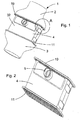
- Fig. 1 shows an embodiment of a heat exchanger according to the invention 1.
- This essentially comprises a first box 2, a first bottom 10, a tube block 4, a second bottom 11 and a second box 3.
- the tube block 4 is surrounded by a cover 32.
- the heat exchanger has a longitudinal direction in which it is flowed through by a charge air flow or an exhaust gas flow.
- Fig. 2 shows an embodiment of the heat exchanger, as it arises after the connection of the tube block 4 with the two floors 10, 11.
- a coolant pipe 5 is arranged, whereby the pipe block 4 coolant can be added or removed.
- Fig. 3 shows a perspective view of a heat exchanger according to the invention, wherein only selected components of the heat exchanger are shown.
- the first floor 10 is connected to both the cover 32 and the first box 2 after assembly of the heat exchanger.
- the boxes 2, 3 have a substantially hood-like shape and in each case an opening on their opposite sides.
- the opening cross-sections are designed such that on the side facing the bottom of the box 2, 3 is a recording in the second gradation 21 of the bottom 10, 11 takes place and on the opposite side to this, the boxes 2, 3 have a substantially circular Cross-section on.
- the boxes 2, 3 are each one-piece components.
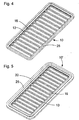
- Fig. 4 shows the rear view of a bottom 10.
- the bottom 10 has a substantially rectangular shape, wherein the corner regions are each rounded.
- passage openings 16 and web-like pipe spacers 13 are arranged alternately transversely to the longitudinal direction of the floor 10, wherein the web-like pipe spacers 13 are regularly spaced apart.
- the through holes 16 receive the plurality of tubes of the tube block (not shown).
- the passage openings 16 have a substantially rectangular shape, wherein the corners may be rounded.
- the profile elevation 25 is formed in the edge region of the bottom 10, which is formed as a circumferential groove.
- Fig. 5 an embodiment of the bottom 10 'according to the present invention is shown.
- the same reference numbers refer to the same Components and features.
- the embodiment of the bottom 10 ' has an additional bottom projection 30 in relation to the first bottom 10, which in particular with a small distance between the coolant connection 5 and the second step 21 in the longitudinal direction of the heat exchanger, welding the bottom 10' to the associated box 2, 3 allows and additionally significantly reduces the distortion of the bottom 10 'and box 2, 3 during welding.
- a section through the bottom 10 for the edge region of the bottom 10 is shown. Inside the bottom 10, a plurality of through openings 16, which alternate with web-like Rohrbeabstandem 13, arranged.
- a skirt 7 is formed, which comprises a first gradation 20 and a second gradation 21, the second gradation 21 being arranged offset in the region of the first gradation 20 to the outside.
- the two steps 20, 21 each form an area on the side facing the box which is essentially planar.
- a profiling increase 25 is formed, which extends from the edge of the bottom 10 to the interior of the bottom 10 substantially to the region of the second step 21 down.
- a bottom recess 22 is formed, which extends into the interior of the bottom 10.
- the bottom recess 22 extends on the side facing away from the box of the bottom 10 to the interior of the bottom 10 towards a second recess 50 which is offset from the bottom recess 22 to the outside and in its edge region, the bottom groove 26 to Recording the cover 32 forms.
- Fig. 7 shows a section through the embodiment of the bottom 10 'for the edge region of the bottom 10'.
- a third step 26 is formed on the side of the bottom 10' facing the box, which is offset outwards relative to the second step 21, whereby a groove is formed between the first step 20 and the third step 26, in which the box extends.
- the upper edge of the first step 20 and the upper edge of the third step 26 are arranged substantially on one level.
- the third step 26 forms outwardly a bottom overhang 30.
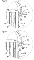
- Fig. 8 shows an enlarged sectional view for the area "A" according to Fig. 1 with a bottom 10.
- the bottom 10 connects the first box 2 and the tube block 4.
- the first box 2 extends into the second step 21.
- a gap is formed between the inside of the first box 2 and the first step 20.
- On the side facing away from the first box 2 of the first bottom 10 a profiling increase 25 is formed, which is a circumferential groove. Between the cover 32 and the profiling elevation 25, a gap in the region of the bottom recess 22 is formed.
- the plurality of tubes 10 in the chamber 6 are received by the through holes in the first floor 10 and the second floor 11 (not shown).
- the tubes 10 are separated in the longitudinal direction of the bottom 10 by web-like pipe spacers 13 from each other.
- the tube block 4 is delimited by the cover 32 from the environment.
- the cover 32 extends in the first floor 10 in the bottom groove 26, whereby it fixes the cover 32 during assembly of the tube block 4 in the first floor 10.
- Fig. 9 shows a heat exchanger according to the invention, which only by the embodiment of the bottom 10 'of the heat exchanger of Fig. 8 different. The following is therefore only compared to the difference Fig. 8 received.
- the second floor 10 ' has a bottom projection 30 in the edge region, which is approximately 5 mm.
- a groove is formed in the region of the second step 21, into which the first case 2 extends. This groove is essentially a circumferential groove.
- the upper edge of the first gradation and the upper edge of the third gradation lie essentially on one level.
Landscapes
- Engineering & Computer Science (AREA)
- Mechanical Engineering (AREA)
- General Engineering & Computer Science (AREA)
- Physics & Mathematics (AREA)
- Thermal Sciences (AREA)
- Chemical & Material Sciences (AREA)
- Combustion & Propulsion (AREA)
- Heat-Exchange Devices With Radiators And Conduit Assemblies (AREA)
Description
Die Erfindung betrifft einen Wärmetauscher, insbesondere Ladeluftkühler oder Abgaskühler für eine Brennkraftmaschine eines Kraftfahrzeuges und dessen Herstellungsverfahren.The invention relates to a heat exchanger, in particular intercooler or exhaust gas cooler for an internal combustion engine of a motor vehicle and its manufacturing method.
Bekannt sind bereits Wärmetauscher, die als sogenannte Ganzaluminium-Wärmetauscher ausgebildet sind. Weiter ist bekannt, dass solche Wärmetauscher bzw. Ganzaluminium-Wärmetauscher als Ladeluftkühler für eine Brennkraftmaschine eingesetzt werden können. Bekannte Ladeluftkühler weisen zwei beabstandete Kästen auf, die über eine Vielzahl von Rohren, wie Flachrohre, strömungsverbunden sind. Die zu kühlende Ladeluft strömt dann von dem einen der beiden Kästen durch die Rohre in den anderen der beiden Kästen. Zwischen den Rohren sind quer zu ihrer Längserstreckungsrichtung Zwischenräume vorgesehen, die von einem Kühlmittel durchströmt werden können. Der von diesen Rohren gebildete Rohrblock ist dabei von einem separaten, um den Rohrblock umfangsmäßig geschlossenen und eine Abdeckung bzw. Ummantelung bildenden Blech umgeben, so dass zwischen den beiden Kästen eine Kammer ausgebildet wird, durch welche die Rohre verlaufen. Diese Ummantelung ist mit einem Zulauf sowie einem Ablauf für Kühlmittel versehen.Heat exchangers are already known which are designed as so-called all-aluminum heat exchangers. It is also known that such heat exchangers or all-aluminum heat exchangers can be used as intercoolers for an internal combustion engine. Known intercoolers have two spaced boxes, which are flow connected via a plurality of tubes, such as flat tubes. The charge air to be cooled then flows from one of the two boxes through the pipes into the other of the two boxes. Between the tubes are transverse to their longitudinal direction Provided intermediate spaces, which can be flowed through by a coolant. The tube block formed by these tubes is surrounded by a separate, circumferentially closed around the tube block and a cover or sheath forming sheet, so that between the two boxes, a chamber is formed through which the tubes extend. This jacket is provided with an inlet and a drain for coolant.
Bekannt ist bei solchen Gestaltungen, dass als Ganzaluminium-Wärmetauscher gestaltete Ladeluftkühler jeweils einen Kasten sowie einen Boden auf einer Seite des Rohrblocks aufweisen. Der Kasten bildet dabei eine Art Haube aus, die auf ihrer offenen Seite durch den Boden verschlossen wird. Im Boden sind dabei mehrere Durchgangsöffnungen vorgesehen, in welche die Rohre eingesetzt sind. Der bzw. die Böden werden daher auch als Rohrboden bzw. Rohrböden bezeichnet. Das Einsetzen der Rohre in diese Böden erfolgt in der Regel vor dem Zusammenfügen der betreffenden Böden mit den ihnen jeweils zugeordneten Kästen. Bei derartigen Gestaltungen werden einerseits die Rohre mit den Böden und andererseits die Böden mit den Kästen über geeignete Verbindungsmittel verbunden. Bekannt ist beispielsweise, dass die Rohre mit den Böden verlötet werden und die Böden mit den Kästen verlötet werden.It is known in such designs that configured as a whole aluminum heat exchanger intercooler each having a box and a bottom on one side of the tube block. The box forms a kind of hood, which is closed on its open side by the ground. In the floor while several through holes are provided, in which the tubes are used. The or the floors are therefore also referred to as tube sheet or tube sheets. The insertion of the pipes in these floors is usually done before joining the respective floors with their respective associated boxes. In such designs, on the one hand, the pipes are connected to the floors and, on the other hand, the floors are connected to the boxes via suitable connecting means. It is known, for example, that the pipes are soldered to the floors and the floors are soldered to the boxes.
Im Stand der Technik ist aus der
Bekannt sind weiter Ausgestaltungen derartiger Kästen, bei denen kein separater Boden vorhanden ist und die lediglich einen Kasten aufweisen. Bei solchen Gestaltungen sind die Rohre in ihren dem jeweilige Kasten zugewandten Endbereichen aufgeweitet und in den aufgeweiteten Bereichen miteinander verlötet.Further known embodiments of such boxes, in which no separate floor is present and have only a box are known. In such designs, the tubes are widened in their end portions facing the respective box and brazed together in the widened areas.
Der Erfindung liegt die Aufgabe zugrunde, einen - insbesondere als Ganzaluminium-Wärmetauscher gestalteten - Wärmetauscher, wie Ladeluftkühler oder Abgaskühler für eine Brennkraftmaschine eines Kraftfahrzeugs, zu schaffen, und insbesondere die Verbindung zwischen Boden und Kasten, sowie zwischen Boden und Abdeckung weiter zu verbessern. Des weiteren ist es die Aufgabe der Erfindung, ein Verfahren für die Herstellung eines erfindungsgemäßen Wärmetauschers zur Verfügung zu stellen.The invention has for its object to provide a - designed especially as a whole aluminum heat exchanger - heat exchanger, such as intercooler or exhaust gas cooler for an internal combustion engine of a motor vehicle, and in particular to improve the connection between the ground and the box, and between the floor and cover on. Furthermore, it is the object of the invention to provide a process for the production of a heat exchanger according to the invention.
Diese Aufgabe wird erfindungsgemäß durch den Wärmetauscher gemäß Anspruch 1 gelöst. Das entsprechende Verfahren für die Herstellung eines erfindungsgemäßen Wärmetauschers zeigt Anspruch 9. Bevorzugte Weiterbildungen sind Gegenstand der Unteransprüche.This object is achieved by the heat exchanger according to
Ein erfindungsgemäßer Wärmetauscher weist einen ersten Kasten, sowie einen von diesem beabstandet angeordneten zweiten Kasten auf, der mit dem zweiten Kasten über eine Vielzahl von Rohren strömungsverbunden ist Der Wärmetauscher weist ferner eine von einem Kühlmittel durchströmbare Kammer auf die zwischen den beiden Kästen angeordnet ist und durch welche mehrere oder alle dieser Rohre verlaufen. Jeder Kasten ist durch einen Boden abgeschlossen, der mit einer oder mehreren Durchgangsöffnungen zur Aufnahme der Rohre versehen ist. Wenigstens ein Boden weist eine von den Rohren nach außen weg weisende Einfassung auf, und ist mit einer ersten Abstufung und einer zweiten Abstufung versehen. Die Einfassung ist im Wesentlichen im Randbereich des Bodens angeordnet und die zweite Abstufung ist im Bereich der ersten Abstufung von der ersten Abstufung nach außen versetzt angeordnet.A heat exchanger according to the invention comprises a first box, as well as a second box spaced therefrom, which is fluidly connected to the second box via a plurality of tubes. The heat exchanger further comprises a chamber through which a coolant can flow and is arranged between the two boxes which run several or all of these tubes. Each box is closed by a bottom which is provided with one or more through holes for receiving the tubes. At least one floor has one of the skirt facing outwardly facing skirt, and is provided with a first step and a second step. The enclosure is arranged substantially in the edge region of the floor and the second step is arranged offset in the region of the first gradation from the first step outwards.
Durch den Hitzeeintrag beim Schweißen des Kastens kann es zu Undichtigkeiten in nahe gelegenen Lötverbindungen kommen. Wird nun der Boden auf der dem Kasten zugewandten Seite mit zwei Abstufungen und auf der dem Kasten gegenüberliegenden Seite mit einer erfindungsgemäßen Boden-Aussparung versehen, so wird der Abstand zwischen der Schweißstelle am Kasten und der nächst liegenden Lötstelle, insbesondere die Lötstelle im Bereich der Abdeckung, vergrößert. Dies führt dazu, dass die Temperatur an der nächstliegenden Lötstelle die Schmelztemperatur des Lots dann nicht mehr erreicht.The heat input when welding the box may cause leaks in nearby solder joints. Now, if the bottom on the side facing the box with two gradations and on the opposite side of the box provided with a bottom recess according to the invention, the distance between the weld on the box and the nearest solder joint, in particular the solder joint in the region of the cover , enlarged. As a result, the temperature at the nearest solder joint no longer reaches the melting temperature of the solder.
Die Rohre sind mit ihrem jeweiligen einen Ende in die Durchgangsöffnungen des ersten Bodens mit ihrem jeweiligen anderen Ende in die des zweiten Bodens eingesteckt. Es ist vorgesehen, dass einer der Kästen oder beide Kästen jeweils so gestaltet sind, dass der Boden dieses Kastens bzw. der jeweilige Boden des jeweiligen Kastens eine Boden-Nut besitzt, welche die Abdeckung beim Kassettieren fixiert und die zweite Abstufung bzw. im Fall der zweiten Ausführungsform des Bodens eine Nut aufweist, die den Kasten fixiert und den für das Schweißen benötigten Mindestabstand von 7-10 mm von der Schweißnaht bis zur nächsten Lötverbindung (Abdeckung - Boden bzw. Rohr - Boden) aufweist.The tubes are inserted with their respective one end in the through holes of the first bottom with their respective other end in the second bottom. It is envisaged that one of the boxes or both boxes are each designed so that the bottom of this box or the respective bottom of each box has a bottom groove which fixes the cover in Kassettieren and the second gradation or in the case of second embodiment of the bottom has a groove which fixes the box and needed for welding Minimum distance of 7-10 mm from the weld to the next solder joint (cover - bottom or pipe - bottom).
Die Abdeckung kann beispielsweise so gestaltet sein, dass sie die Kammer zu einer Seite begrenzt; sie kann aber auch so sein, dass sie eine im Wesentlichen umfangsmäßig im Wesentlichen geschlossene Hülle für die Begrenzung der Kammer bildet, oder auf andere Weise gestaltet sein. Es kann auch vorgesehen sein, dass sie mehrteilig gestaltet ist, bzw. dass mehrere Abdeckungen, wie Abdeckbleche, vorgesehen sind, die sich in vorerwähnter Weise - insbesondere mit einem Randbereich - in eine (jeweilige) Nut bzw. jeweilige Nuten erstrecken, die im Boden des ersten Kastens und / oder im Boden des zweiten Kastens vorgesehen ist. Beispielsweise kann auf zwei gegenüberliegenden Seiten des von den Rohren gebildeten Rohrblocks jeweils eine derartige Abdeckung bzw. ein derartiges Abdeckblech vorgesehen sein.For example, the cover may be configured to confine the chamber to one side; but it can also be such that it forms a substantially circumferentially substantially closed shell for the boundary of the chamber, or be designed in other ways. It may also be provided that it is designed in several parts, or that a plurality of covers, such as cover plates, are provided, which extend in the aforementioned manner - in particular with an edge region - in a (respective) groove or respective grooves in the ground of the first box and / or in the bottom of the second box. For example, such a cover or such a cover plate may be provided on two opposite sides of the tube block formed by the tubes.
Gemäß einer besonders zu bevorzugenden Weiterbildung wird die zwischen den Kästen vorgesehene Kammer auf den in Längserstreckungsrichtung der Rohre gegenüberliegenden Seiten von den Kästen begrenzt. Dies ist in einer vorteilhaften Ausgestaltung so, dass die Kammer auf der einen der beiden in Längserstreckungsrichtung der Rohre gegenüberliegenden Seiten von dem Boden des ersten Kastens begrenzt wird, und auf der anderen dieser beiden in Längserstreckungsrichtung der Rohre gegenüberliegenden Seiten von dem Boden des zweiten Kastens begrenzt wird.According to a particularly preferable development, the chamber provided between the boxes is bounded by the boxes on the opposite sides in the longitudinal direction of the tubes. This is in an advantageous embodiment such that the chamber is bounded on one of the two opposite sides in the longitudinal direction of the tubes from the bottom of the first box, and limited on the other of these two opposite in the longitudinal direction of the tubes sides of the bottom of the second box becomes.
Ein erfindungsgemäßer Wärmetauscher ist so gestaltet, dass das Rohrbündel (Rohre, Innenrippen, Turbulenzeinlagen, Abdeckungen, Böden) verlötet wird und anschließend auf den verlöteten Block die gegossenen Kasten, vorzugsweise aus Aluminiumguss, fluiddicht verschweißt werden.An inventive heat exchanger is designed so that the tube bundle (tubes, inner fins, turbulence inserts, covers, floors) is soldered and then the cast case, preferably cast aluminum, fluid-tight welded to the soldered block.
Der Boden des ersten Kastens und / oder der Boden des zweiten Kastens weist auf der dem Kasten zugewandten Seite wenigstens eine umlaufende Abstufung und eine zweite umlaufende Abstufung bzw. eine umlaufende Nut zur Fixierung des Kastens auf.The bottom of the first box and / or the bottom of the second box has on the side facing the box at least one circumferential step and a second circumferential step or a circumferential groove for fixing the box.
Wie auch die vorstehenden Ausführungen zeigen, können die Ausgestaltungen des Kastens bzw. des Bodens und das Zusammenwirken von Kasten und Boden bzw. das Zusammenwirken von Boden und Abdeckung sich auf einen der beiden Kasten beziehen oder auf beide Kästen.As shown in the foregoing, the box and floor designs and the box-floor interaction, or the floor-cover interaction, may relate to one of the two boxes or to both boxes.
Gemäß der Erfindung ist vorgesehen, dass eine erste Profilierungserhöhung quer, insbesondere senkrecht, zur Längserstreckungsrichtung der Rohre von dem von den Rohren, insbesondere Flachrohren, gebildeten Rohrblock beabstandet ist, so dass quer, insbesondere senkrecht, zur Längserstreckungsrichtung der Rohre wenigstens ein erster Zwischenraum zwischen diesem Rohrblock und dieser ersten Profilierungserhöhung gebildet wird, wobei für die Begrenzung der Kammer zumindest eine Abdeckung, insbesondere Abdeckblech, vorgesehen ist, und wobei sich ein - insbesondere endseitiger - Wandabschnitt bzw. Rand dieser Abdeckung in diesen ersten Zwischenraum erstreckt. Dabei kann vorgesehen sein, dass dieser sich in den zwischen dem Rohrblock und der ersten Profilierungserhöhung gebildeten ersten Zwischenraum erstreckende Wandabschnitt der Abdeckung im Wesentlichen an diesem Rohrblock und / oder an dieser ersten Profilierungserhöhung anliegt und / oder mit Rohren des Rohrblocks und / oder mit der ersten Profilierungserhöhung, beispielsweise mittels Lotplattierung, verlötet ist.According to the invention, it is provided that a first profiling increase is spaced transversely, in particular perpendicularly, to the longitudinal direction of the tubes from the tube block formed by the tubes, in particular flat tubes, so that transversely, in particular perpendicularly, to the longitudinal extension direction of the tubes at least a first intermediate space between them Pipe block and this first profiling increase is formed, wherein for the limitation of the chamber at least one cover, in particular cover plate, is provided, and wherein a - in particular end-side - wall portion or edge of this cover extends into this first space. It can be provided that this in the formed between the tube block and the first profiling increase first space extending wall portion of the cover is substantially applied to this tube block and / or at this first profiling increase and / or with tubes of the tube block and / or with the first Profilierungserhöhung, for example by means of solder plating, is soldered.
Besonders vorteilhaft ist eine bevorzugte Ausgestaltung, gemäß der sich - wie zuvor erwähnt - ein Wandabschnitt der Abdeckung in eine Boden-Nut dieses Bodens der genannten Art erstreckt. Wenigstens ein Boden weist auf der dem Kasten zugewandten Seite eine dritte Abstufung mit einer Oberkante auf, wobei die Oberkante in einer Ebene mit der ersten Abstufung liegt. Die zweite Abstufung bildet zwischen der ersten Abstufung und der dritten Abstufung eine Nut. Ist der Kühlmittelstutzen zu Nahe am Boden angeordnet, insbesondere falls der Abstand zwischen der Schweißnaht für den Kasten und dem Kühlmittelstutzen < 10 mm beträgt, und somit den Schweißprozess behindert, so weist die dem Kasten zugewandten Seite des Bodens eine dritte Abstufung auf. Der Kasten erstreckt sich dann in die oben genannte Nut. Diese Nut ist vorteilhafterweise eine umlaufende oder eine im Wesentlichen umlaufende Nut.Particularly advantageous is a preferred embodiment, according to which - as mentioned above - a wall portion of the cover extends into a bottom groove of this floor of the type mentioned. At least one floor has on the side facing the box a third step with an upper edge, wherein the upper edge lies in a plane with the first step. The second step forms a groove between the first step and the third step. If the coolant nozzle is arranged too close to the bottom, in particular if the distance between the weld seam for the box and the coolant nozzle is <10 mm, and thus hinders the welding process, the side of the base facing the box has a third step. The box then extends into the above groove. This groove is advantageously a circumferential or a substantially circumferential groove.
Des Weiteren wird in einer Ausführungsform im äußeren Randbereich des Bodens ein Bodenüberstand ausgebildet. Der Bodenüberstand wenigstens eines Bodens beträgt bevorzugt zwischen 3 mm und 10 mm, vorzugsweise 5 mm. Für das Fügen von einem diesen Boden und wenigstens einem Kasten wird bevorzugt ein stoffschlüssiges Fügeverfahren, insbesondere Schweißen, eingesetzt, wodurch der Boden im Bereich des Bodenüberstands in seiner Ausdehnung nach außen abnimmt, und den Wärmetauscher insbesondere fluiddicht verschweißt. Das Verschweißen kann beispielsweise mittels Laserschweißen, WIG- und MIG-Schweißen oder auf andere Weise erfolgt sein. Der Bodenüberstand wird durch den Schweißprozess abgetragen, sodass nach dem Schweißen nur noch ein geringer bzw. gar kein Bodenüberstand vorhanden ist.Furthermore, in one embodiment, a bottom overhang is formed in the outer edge region of the bottom. The bottom projection of at least one bottom is preferably between 3 mm and 10 mm, preferably 5 mm. For the joining of a bottom and at least one box, a cohesive joining method, in particular welding, is preferably used, whereby the bottom in the area of the bottom projection decreases outward in its extent, and in particular welded fluid-tight to the heat exchanger. The welding can be done for example by means of laser welding, TIG and MIG welding or in another way. The ground overhang is removed by the welding process, so that after welding only a small or no ground overhang is present.
In einem erfindungsgemäßen Wärmetauscher erstreckt sich wenigstens ein Kasten, bzw. ein Wandabschnitt desselben Kastens in die zweite Abstufung dieses Bodens.In a heat exchanger according to the invention extends at least one box, or a wall portion of the same box in the second gradation of this soil.
In einem erfindungsgemäßen Wärmetauscher ist auf einer dem Kasten abgewandten Seite wenigstens eines Bodens eine Boden-Aussparung ausgebildet, welche sich vorzugsweise von der ersten Profilierungserhöhung des Bodens zur Innenseite des Bodens hin erstreckt. Durch die Boden-Aussparung wird vorzugsweise ein Spalt zwischen der Abdeckung und der ersten Profilierungserhöhung gebildet.In a heat exchanger according to the invention a bottom recess is formed on a side facing away from the box at least one bottom, which preferably extends from the first profiling of the soil to the inside of the soil. The bottom recess preferably forms a gap between the cover and the first profiling elevation.
Es ist vorgesehen, dass bei einem erfindungsgemäßen Wärmetauscher wenigstens ein Kasten vorzugsweise mit einem gießtechnischen Verfahren, insbesondere mit dem Druckguss-Verfahren, hergestellt wird. Der gegossene Kasten hat standardmäßig eine Wanddicke von ≥ 3 mm. Gegossene Kästen weisen des Weiteren den Vorteil auf, dass evtl. erforderliche Halter direkt mitgegossen werden können (Kasten und Halter aus einem Bauteil).It is envisaged that in a heat exchanger according to the invention, at least one box is preferably produced by a casting process, in particular by the die-casting method. The cast box has a standard wall thickness of ≥ 3 mm. Cast boxes also have the advantage that any necessary holders can be cast directly (box and holder from a component).
Bevorzugt ist ferner, dass die wenigstens eine Abdeckung, insbesondere Abdeckblech, mit dem Boden verlötet ist. In vorteilhafter Ausgestaltung ist vorgesehen, dass das Lot, mittels welchem der Boden und die Abdeckung verlötet sind, im Bereich des zwischen der Profilierungserhöhung und der Boden-Aussparung gebildeten Zwischenraums gegeben ist.It is further preferred that the at least one cover, in particular cover plate, is soldered to the floor. In an advantageous embodiment, it is provided that the solder, by means of which the bottom and the cover are soldered, is provided in the region of the intermediate space formed between the profiling elevation and the bottom recess.
Die Abdeckung ist in vorteilhafter Weise im Bereich des Zwischenraums, der zwischen der ersten Profilierungserhöhung des Bodens und der Abdeckung ausgebildet wird, mit dieser ersten Profilierungserhöhung und / oder mit den dortigen Rohrabschnitten von Rohren des Rohrblocks verlötet oder - in alternativer Gestaltung - im Bereich der Boden-Nut, so dass Lot in dieser Boden-Nut gegeben ist. Das Verlöten erfolgt in vorteilhafter Weiterbildung mittels Lotplattierung.The cover is advantageously in the region of the intermediate space, which is formed between the first profiling of the soil and the cover, soldered to this first profiling and / or with the local pipe sections of tubes of the tube block or - in an alternative design - in the field of soil -Nut, so that solder is given in this soil groove. The soldering takes place in an advantageous development by means of solder plating.
Gemäß einer vorteilhaften Weiterbildung ist der Boden im Wesentlichen flach bzw. eben ausgebildet ist.According to an advantageous development of the soil is substantially flat or flat.
Die wenigstens eine Abdeckung kann aus Blech geformt sein. Der Boden bzw. die Böden sind vorteilhafter Weise einstückig ausgebildet bzw. aus einem einstückigen Teil gefertigt.The at least one cover may be formed from sheet metal. The soil or the floors are advantageously integrally formed or made of a one-piece part.
Es ist insbesondere vorgesehen, dass die bzw. sämtliche Rohre in der quer zu der Längserstreckungsrichtung gesehenen Richtung beabstandet sind, so dass Rohrzwischenräume für eine Durchströmung mit einem von einem durch die Rohre strömenden Medium (insbesondere Abgas oder Ladeluft) verschiedenen Medium (insbesondere Kühlmittel) ausgebildet werden. Solche Rohrzwischenräume können insbesondere jeweils zwischen benachbarten Rohren gegeben sein. Die Rohre können in ihrem Inneren einen oder mehrere Kanäle ausbilden. Anzumerken ist, dass als "Rohrblock" im Sinne dieser Anmeldung die Einheit der Rohre - insbesondere in ihrer montierten Anordnung - bezeichnet wird. Der Begriff "Rohrblock" schließt also die angesprochenen Rohrzwischenräume nicht aus, und soll insbesondere nicht anzeigen, dass die Rohre in Kontakt miteinander stehen müssen.It is provided in particular that the or all tubes are spaced in the direction transverse to the direction of longitudinal extension, so that pipe interspaces for a flow with one of a medium flowing through the tubes (in particular exhaust gas or charge air) different medium (in particular coolant) is formed become. Such pipe interspaces may in particular be given in each case between adjacent pipes. The tubes can form one or more channels in their interior. It should be noted that as "tube block" in the context of this application, the unit of the tubes - especially in their assembled arrangement - is called. The term "tube block" thus does not exclude the mentioned tube interstices, and in particular does not indicate that the tubes must be in contact with each other.
Beispielsweise kann auch vorgesehen sein, dass in die Rohrzwischenräume Turbulenzeinlagen eingesetzt sind. Diese können beispielsweise die jeweils benachbarten Rohre kontaktieren und / oder mit diesen verlötet sein, und zwar insbesondere mittels Lotplattieren.For example, it can also be provided that turbulence inserts are inserted into the tube interspaces. These can, for example, contact the respectively adjacent tubes and / or be soldered to them, in particular by means of solder plating.
Die Kammer kann eine Einlassöffnung für ein Kühlmittel, wie Wasser oder dergleichen, sowie eine Auslassöffnung für das Kühlmittel aufweisen.The chamber may include an inlet port for a coolant, such as water or the like, and an outlet port for the coolant.
Es kann vorgesehen sein, dass in den Rohren Rippen vorgesehen sind, und zwar insbesondere zur Verbesserung der Wärmeleitung.It can be provided that ribs are provided in the tubes, in particular for improving the heat conduction.
Besonders bevorzugt ist vorgesehen, dass der Wärmetauscher ein Ladeluftkühler oder ein Abgaskühler für eine Brennkraftmaschine eines Kraftfahrzeugs ist. Dabei kann vorgesehen sein, dass die Ladeluft bzw. das Abgas mittels dieses Ladeluftkühlers bzw. Abgaskühlers abgekühlt werden kann. Es kann vorgesehen sein, dass die Ladeluft bzw. das Abgas in den einen der beiden Kästen des Wärmetauschers eintritt, und anschließend durch die Rohre in den anderen der beiden Kästen strömt. Durch die Rohrzwischenräume bzw. die angesprochene Kammer kann dabei ein Kühlmittel strömen.Particularly preferably, it is provided that the heat exchanger is a charge air cooler or an exhaust gas cooler for an internal combustion engine of a motor vehicle is. It can be provided that the charge air or the exhaust gas can be cooled by means of this charge air cooler or exhaust gas cooler. It can be provided that the charge air or the exhaust gas enters the one of the two boxes of the heat exchanger, and then flows through the pipes in the other of the two boxes. Through the pipe interspaces or the addressed chamber can flow a coolant.
In vorteilhafter Ausgestaltung ist der erfindungsgemäße Wärmetauscher ein sogenannter Ganzaluminium-Wärmetauscher bzw. besteht im Wesentlichen vollständig aus Aluminium.In an advantageous embodiment, the heat exchanger according to the invention is a so-called all-aluminum heat exchanger or consists essentially entirely of aluminum.
Die Rohre, über welche der erste Kasten mit dem zweiten Kasten strömungsverbunden ist, sind vorzugsweise - insbesondere alle - Flachrohre. Bevorzugt ist ferner, dass die bzw. sämtliche Rohre, über welche der erste Kasten mit dem zweiten Kasten strömungsverbunden ist, parallel zueinander verlaufen. Die Rohre, über welche der erste Kasten mit dem zweiten Kasten strömungsverbunden ist, sind insbesondere zwischen dem ersten Kasten und dem zweiten Kasten angeordnet.The tubes, via which the first box is flow-connected to the second box, are preferably-in particular all-flat tubes. It is further preferred that the or all tubes, via which the first box is flow-connected to the second box, parallel to each other. The tubes, via which the first box is flow-connected to the second box, are arranged in particular between the first box and the second box.
In einer weiteren vorteilhaften Ausführung weist der Wärmetauscher mindestens eine Aussparung, insbesondere mehrere Aussparungen, auf. Durch die Aussparung kann insbesondere während des Fügeprozesses, insbesondere während des Lötprozesses, besonders vorteilhaft eine Kraft auf die Rohre aufgebracht werden.In a further advantageous embodiment, the heat exchanger has at least one recess, in particular a plurality of recesses. Due to the recess, a force can be applied to the tubes particularly advantageously during the joining process, in particular during the soldering process.
Zur Herstellung eines erfindungsgemäßen Wärmetauschers werden zuerst die Enden einer Vielzahl von Rohren durch die Durchgangsöffnungen des ersten Bodens geführt. Danach wird die Abdeckung oder, falls die Abdeckung mehrteilig ausgeführt ist, die Teile der Abdeckung um die Rohre angeordnet, wobei diese sich in die Boden-Nut des ersten Bodens erstrecken. Anschließend wird der zweite Boden auf der dem ersten Boden gegenüber liegenden Seite aufgesetzt, so dass die Rohre durch die Durchgangsöffnungen des zweiten Bodens geführt sind. Dann werden die Endbereiche der Rohre entlang ihres Umfangs mit den Böden durch Löten verbunden. Anschließend werden die Abdeckung oder die Teile der Abdeckung mit den Böden im Bereich der jeweiligen Boden-Aussparung oder im Bereich der Boden-Nut durch Löten verbunden. Als nächstes werden die Kästen auf jeweils einen Boden aufgesetzt und durch die jeweilige zweite Abstufung des jeweiligen Bodens fixiert. Danach werden die Kästen mit dem jeweiligen Boden durch Schweißen verbunden.To produce a heat exchanger according to the invention, the ends of a plurality of tubes are first led through the passage openings of the first floor. Thereafter, the cover or, if the cover is made in several parts, the parts of the cover are arranged around the tubes, which extend into the bottom groove of the first floor. Subsequently, the second floor is placed on the opposite side of the first floor, so that the tubes are passed through the through holes of the second floor. Then, the end portions of the tubes are joined along their circumference to the bottoms by brazing. Subsequently, the cover or the parts of the cover are connected to the floors in the region of the respective bottom recess or in the region of the bottom groove by soldering. Next, the boxes are placed on a respective bottom and fixed by the respective second gradation of the respective soil. Thereafter, the boxes are connected to the respective floor by welding.
Nach dem erfindungsgemäßen Herstellungsverfahren kann ein Wärmetauscher, wie er vorstehend beschrieben wurde, kostengünstig und/oder in einer kurzen Herstellungszeit erzeugt werden. Durch die gegenüber dem Stand der Technik nach außen hin größere Beabstandung von Schweiß- und Lötstelle wird die thermische Belastung für die Lötstelle deutlich verringert. Dies reduziert vorteilhaft die Gefahr einer Undichtigkeit der Lötverbindungen und erhöht damit die Fertigungsqualität.According to the manufacturing method of the present invention, a heat exchanger as described above can be produced inexpensively and / or in a short production time. By compared to the prior art outwardly larger spacing of welding and soldering the thermal load on the solder joint is significantly reduced. This advantageously reduces the risk of leakage of the solder joints and thus increases the manufacturing quality.
Im Folgenden sollen nun beispielhafte Ausführungsformen der Erfindung anhand der Figuren näher erläutert werden. Es zeigt:
- Fig. 1
- eine perspektivische Ansicht eines Wärmetauschers nach einer Ausführungsform der vorliegenden Erfindung,
- Fig. 2
- eine perspektivische Ansicht eines Rohrblocks mit jeweils einem Boden an dessen Ende,
- Fig. 3
- eine perspektivische Explosionsansicht für ausgewählte Bauteile eines Wärmetauschers nach einer Ausführungsform der vorliegenden Erfindung,
- Fig. 4
- eine perspektivische Ansicht eines Bodens,
- Fig. 5
- eine perspektivische Ansicht einer Ausführungsform des Bodens gemäß der vorliegenden Erfindung,
- Fig. 6
- eine Schnittdarstellung eines Bodens,
- Fig. 7
- eine Schnittdarstellung der Ausführungsform des Bodens gemäß der vorliegenden Erfindung,
- Fig. 8
- eine Schnittdarstellung für den Bereich "A" gemäß
Fig. 1 des Wärmetauschers mit einem Boden.
- Fig. 9
- eine Schnittdarstellung für den Bereich "A" gemäß
Fig. 1 des Wärmetauschers nach einer Ausführungsform der vorliegenden Erfindung mit einer Ausführungsform des Bodens.
- Fig. 1
- a perspective view of a heat exchanger according to an embodiment of the present invention,
- Fig. 2
- a perspective view of a tube block, each with a bottom at the end,
- Fig. 3
- an exploded perspective view of selected components of a heat exchanger according to an embodiment of the present invention,
- Fig. 4
- a perspective view of a floor,
- Fig. 5
- a perspective view of an embodiment of the soil according to the present invention,
- Fig. 6
- a sectional view of a floor,
- Fig. 7
- a sectional view of the embodiment of the soil according to the present invention,
- Fig. 8
- a sectional view for the area "A" according to
Fig. 1 of the heat exchanger with a bottom.
- Fig. 9
- a sectional view for the area "A" according to
Fig. 1 the heat exchanger according to an embodiment of the present invention with an embodiment of the soil.
In
In
Claims (9)
- A heat exchanger, in particular a charge air cooler or exhaust gas cooler for an internal combustion engine of a motor vehicle, having a first box (2), a first base (10'), a second box (3) which is arranged spaced apart from this first box (2), a second base (11) and a plurality of pipes (12) by means of which the first box (2) and the second box (3) are fluidically connected, and having a chamber (6) through which a coolant can flow and which is arranged between the two boxes (2, 3) and through which a plurality or all of these pipes (12), by means of which the two boxes (2, 3) are fluidically connected, run and the bases (10', 11) are provided with one or more through openings (16) for receiving the pipes (12), wherein at least one base (10') has a border (7) which points away from the pipes (12) toward the outside and is provided with a first step (20) and a second step (21), wherein the border (7) is arranged essentially in the edge region of the base (10'), and the second step (21) is arranged in the region of the first step (20), offset toward the outside from the first step (20), wherein this at least one base (10') has a third step with an upper edge, wherein the upper edge lies in a plane with the first step (20), wherein at least one box (2, 3) or a wall section (28) of the same box (2, 3) extends into the second step (21) of this base (10'), the base (10') has, on its side facing away from the box (2, 3), at least a first profiling elevation (25), in particular a first profiling elevation (25) which runs around in the outer edge region of the base (10') and on a side of at least one base (10') which faces away from the box (2, 3), a base cut-out (22) is formed which extends from the first profiling elevation (25) of the base (10') to the interior of the base (10').
- The heat exchanger according to claim 1, characterised in that the at least one base (10') forms a groove by a second step (21) between the first step (20) and the third step.
- The heat exchanger according to claim 2, characterised in that the second step (21) is a circumferential or essentially circumferential groove.
- The heat exchanger according to claim 1, 2 or 3, characterised in that at least one cover (32), in particular covering plate, is provided for bounding the chamber (6), and in that the base (10') has at least one base groove (26) on the side facing away from the box, into which base groove a wall section (39) of the cover (32) extends.
- The heat exchanger according to claim 4, characterised in that the base cut-out (22) forms a gap between the cover (32) and the first profiling elevation (25) .
- The heat exchanger according to one of the preceding claims, characterised in that at least one base (10') has a base protrusion (30), wherein said protrusion decreases in its extent toward the outside by virtue of a materially-connecting joining method, in particular welding, for joining a base (10') and at least one box (2, 3).
- The heat exchanger according to one of the preceding claims, characterised in that the base protrusion (30) of a base (10') is between 3 mm and 10 mm, preferably 5 mm.
- The heat exchanger according to one of the preceding claims, characterised in that at least one box (2, 3) is manufactured using a casting method.
- A method for manufacturing a heat exchanger (1) according to one of claims 1 to 8, having the steps:- mounting of the pipe block (4);- connection of the pipes (12) to the base (10') by soldering;- connection of the cover (32) to the base (10') in the region of the base cut-out (22) by soldering; and then- connection of the box (2, 3) to the base (10') by welding.
Applications Claiming Priority (1)
| Application Number | Priority Date | Filing Date | Title |
|---|---|---|---|
| DE102007024630A DE102007024630A1 (en) | 2007-05-24 | 2007-05-24 | Heat exchanger, in particular intercooler or exhaust gas cooler for an internal combustion engine of a motor vehicle and its manufacturing method |
Publications (3)
| Publication Number | Publication Date |
|---|---|
| EP1995544A2 EP1995544A2 (en) | 2008-11-26 |
| EP1995544A3 EP1995544A3 (en) | 2013-08-14 |
| EP1995544B1 true EP1995544B1 (en) | 2018-07-18 |
Family
ID=39731658
Family Applications (1)
| Application Number | Title | Priority Date | Filing Date |
|---|---|---|---|
| EP08008752.1A Expired - Fee Related EP1995544B1 (en) | 2007-05-24 | 2008-05-09 | Heat exchanger, in particular charger air cooler or exhaust gas cooler for a combustion engine of a motor vehicle and manufacturing method therefor |
Country Status (3)
| Country | Link |
|---|---|
| US (1) | US8261815B2 (en) |
| EP (1) | EP1995544B1 (en) |
| DE (1) | DE102007024630A1 (en) |
Families Citing this family (19)
| Publication number | Priority date | Publication date | Assignee | Title |
|---|---|---|---|---|
| JP4121085B2 (en) * | 2001-12-21 | 2008-07-16 | ベール ゲーエムベーハー ウント コー カーゲー | Especially heat exchanger for automobile |
| EP2137478A2 (en) * | 2007-04-11 | 2009-12-30 | Behr GmbH & Co. KG | Heat exchanger |
| DE102009053884A1 (en) * | 2009-11-20 | 2011-06-01 | Behr Gmbh & Co. Kg | Suction tube for an internal combustion engine |
| DE102010040983A1 (en) * | 2010-09-17 | 2012-03-22 | Behr Gmbh & Co. Kg | Gas cooler e.g. indirect intercooler, for motor car, has locking element connected with end edge of housing portions and completely penetrating through pipe base in region of outer pipe in direction of pipes |
| EP2458312B1 (en) | 2010-11-26 | 2018-07-18 | MAHLE International GmbH | Heat exchanger for an internal combustion engine |
| DE102011085479A1 (en) | 2011-10-28 | 2013-05-02 | Behr Gmbh & Co. Kg | Heat exchanger |
| FR2984478A1 (en) * | 2011-12-20 | 2013-06-21 | Valeo Systemes Thermiques | HEAT EXCHANGER, ASSEMBLY OF SUCH AN EXCHANGER AND ONE OR COLLECTING BOXES, AIR INTAKE MODULE COMPRISING SUCH AN ASSEMBLY |
| FR2984476B1 (en) * | 2011-12-20 | 2014-02-28 | Valeo Systemes Thermiques | THERMAL EXCHANGER, IN PARTICULAR FOR MOTOR VEHICLE |
| DE102012214221A1 (en) * | 2012-08-09 | 2014-03-06 | Behr Gmbh & Co. Kg | Heat exchanger |
| CN104019691B (en) | 2012-09-28 | 2017-04-26 | 马勒国际公司 | Heat exchanger |
| DE102012217876A1 (en) * | 2012-09-28 | 2014-04-03 | Behr Gmbh & Co. Kg | Heat exchanger for e.g. lithium-ion battery, in electric car, has circumferential groove that is formed between pipe and opening edge, where groove is closed outwardly by pipe and cover plates fitted to set of headers |
| FR3030709B1 (en) * | 2014-12-18 | 2019-04-05 | Valeo Systemes Thermiques | HEAT EXCHANGER |
| DE102016200456A1 (en) | 2016-01-15 | 2017-07-20 | Mahle International Gmbh | Exhaust gas heat exchanger |
| ES2677368B1 (en) * | 2017-01-31 | 2019-05-14 | Valeo Termico Sa | METHOD FOR THE MANUFACTURE OF A HEAT EXCHANGER FOR GASES AND HEAT EXCHANGER FOR GASES MANUFACTURED WITH THE METHOD |
| DE102017219433B4 (en) | 2017-10-30 | 2022-08-11 | Hanon Systems | Heat exchanger for an internal combustion engine |
| WO2020104836A1 (en) | 2018-11-21 | 2020-05-28 | Valeo North America, Inc. | Charge air cooler |
| DE102019112194A1 (en) * | 2019-05-09 | 2020-11-12 | Mahle International Gmbh | Heat exchanger |
| FR3108395B1 (en) * | 2020-03-20 | 2022-11-11 | Valeo Systemes Thermiques | Motor vehicle heat exchanger |
| EP4342624A1 (en) * | 2022-09-20 | 2024-03-27 | Alfa Laval Vicarb | Heat exchanger module, heat exchanger welding method and heat exchanger assembly |
Family Cites Families (8)
| Publication number | Priority date | Publication date | Assignee | Title |
|---|---|---|---|---|
| JPS57132989U (en) * | 1981-02-04 | 1982-08-19 | ||
| US4485867A (en) * | 1982-02-08 | 1984-12-04 | Ex-Cell-O Corporation | Heat exchanger |
| FR2584488A1 (en) * | 1985-07-03 | 1987-01-09 | Chausson Usines Sa | Method for joining at least one collector plate and one water box to the tubes of a heat exchanger including an application thereof |
| DE4436027A1 (en) * | 1994-10-08 | 1996-04-11 | Behr Gmbh & Co | Sealed connection between tube plate and coolant box |
| FR2805036B1 (en) * | 2000-02-10 | 2002-06-14 | Valeo Thermique Moteur Sa | HEAT EXCHANGER WITH IMPROVED SEAL, PARTICULARLY FOR MOTOR VEHICLE |
| DE10233407B4 (en) * | 2001-07-26 | 2016-02-18 | Denso Corporation | Exhaust gas heat exchanger |
| DE10316756A1 (en) * | 2003-04-10 | 2004-10-28 | Behr Gmbh & Co. Kg | Heat exchangers, in particular intercoolers for motor vehicles |
| DE102006043526A1 (en) | 2005-09-12 | 2007-04-05 | Behr Gmbh & Co. Kg | Heat exchanger e.g. intercooler or exhaust gas cooler, for internal combustion engine of motor vehicle, has tank comprising cover and base, where base is provided with passage openings and groove into which wall section of cover extends |
-
2007
- 2007-05-24 DE DE102007024630A patent/DE102007024630A1/en not_active Withdrawn
-
2008
- 2008-05-09 EP EP08008752.1A patent/EP1995544B1/en not_active Expired - Fee Related
- 2008-05-23 US US12/126,299 patent/US8261815B2/en active Active
Non-Patent Citations (1)
| Title |
|---|
| None * |
Also Published As
| Publication number | Publication date |
|---|---|
| EP1995544A2 (en) | 2008-11-26 |
| DE102007024630A1 (en) | 2008-11-27 |
| US20080289833A1 (en) | 2008-11-27 |
| EP1995544A3 (en) | 2013-08-14 |
| US8261815B2 (en) | 2012-09-11 |
Similar Documents
| Publication | Publication Date | Title |
|---|---|---|
| EP1995544B1 (en) | Heat exchanger, in particular charger air cooler or exhaust gas cooler for a combustion engine of a motor vehicle and manufacturing method therefor | |
| DE10231973B4 (en) | Exhaust gas heat exchanger | |
| EP1929233B1 (en) | Charge-air cooler or exhaust gas cooler for an internal combustion engine of a motor vehicle | |
| EP1929231B1 (en) | Heat exchanger, in particular exhaust gas heat exchanger for motor vehicles | |
| DE69720506T2 (en) | Heat Exchanger | |
| DE60031932T2 (en) | Multiple heat exchanger with two cores | |
| EP1616143B1 (en) | Heat exchanger, especially a charge-air cooler for motor vehicles | |
| DE102007049665A1 (en) | Exhaust gas recirculation cooler, for use in e.g. diesel engine, has housing side wall with inner surface which stays in contact with side wall of pipe so that space is separated from connecting chamber and fluid channels | |
| EP1398589B1 (en) | Coolant radiator | |
| DE10392626T5 (en) | Heat pipe and heat exchanger with such a heat pipe | |
| EP1279805A2 (en) | Air-cooled intake air cooler | |
| EP1518043B1 (en) | Exhaust gas heat exchanger and method for the production thereof | |
| DE10215091A1 (en) | Spiral fin / tube as a heat exchanger | |
| DE102008002430A1 (en) | Exhaust gas heat exchanger with vibration-damped exchanger tube bundle | |
| DE3720483A1 (en) | Heat exchanger | |
| DE102007058149A1 (en) | Heat exchanger, assembly and method of making a heat exchanger | |
| DE19906063A1 (en) | Heat exchanger for carbon dioxide coolant circuit | |
| DE112010002744T5 (en) | Heat exchanger with cast housing and method of making the same | |
| DE102008002746A1 (en) | Heat exchanger for the exhaust system of a motor vehicle, method for producing a heat exchanger and assembly tool for this purpose | |
| EP2863157B1 (en) | Heat exchanger | |
| DE102008046024A1 (en) | heat exchangers | |
| DE102006043526A1 (en) | Heat exchanger e.g. intercooler or exhaust gas cooler, for internal combustion engine of motor vehicle, has tank comprising cover and base, where base is provided with passage openings and groove into which wall section of cover extends | |
| EP1376043B1 (en) | Heat exchanger with diffuser | |
| DE112017005880T5 (en) | Stacked heat exchanger | |
| DE102017214822A1 (en) | HEAT EXCHANGERS |
Legal Events
| Date | Code | Title | Description |
|---|---|---|---|
| PUAI | Public reference made under article 153(3) epc to a published international application that has entered the european phase |
Free format text: ORIGINAL CODE: 0009012 |
|
| AK | Designated contracting states |
Kind code of ref document: A2 Designated state(s): AT BE BG CH CY CZ DE DK EE ES FI FR GB GR HR HU IE IS IT LI LT LU LV MC MT NL NO PL PT RO SE SI SK TR |
|
| AX | Request for extension of the european patent |
Extension state: AL BA MK RS |
|
| PUAL | Search report despatched |
Free format text: ORIGINAL CODE: 0009013 |
|
| AK | Designated contracting states |
Kind code of ref document: A3 Designated state(s): AT BE BG CH CY CZ DE DK EE ES FI FR GB GR HR HU IE IS IT LI LT LU LV MC MT NL NO PL PT RO SE SI SK TR |
|
| AX | Request for extension of the european patent |
Extension state: AL BA MK RS |
|
| RIC1 | Information provided on ipc code assigned before grant |
Ipc: F28F 9/02 20060101ALI20130708BHEP Ipc: F02M 25/07 20060101ALI20130708BHEP Ipc: F28D 7/16 20060101AFI20130708BHEP Ipc: F02B 29/04 20060101ALI20130708BHEP |
|
| 17P | Request for examination filed |
Effective date: 20140214 |
|
| RBV | Designated contracting states (corrected) |
Designated state(s): AT BE BG CH CY CZ DE DK EE ES FI FR GB GR HR HU IE IS IT LI LT LU LV MC MT NL NO PL PT RO SE SI SK TR |
|
| AKX | Designation fees paid |
Designated state(s): DE FR |
|
| RAP1 | Party data changed (applicant data changed or rights of an application transferred) |
Owner name: MAHLE BEHR GMBH & CO. KG |
|
| 17Q | First examination report despatched |
Effective date: 20170102 |
|
| GRAP | Despatch of communication of intention to grant a patent |
Free format text: ORIGINAL CODE: EPIDOSNIGR1 |
|
| RIC1 | Information provided on ipc code assigned before grant |
Ipc: F02B 29/04 20060101ALI20180205BHEP Ipc: F28F 9/02 20060101ALI20180205BHEP Ipc: F28D 7/16 20060101AFI20180205BHEP |
|
| INTG | Intention to grant announced |
Effective date: 20180301 |
|
| GRAS | Grant fee paid |
Free format text: ORIGINAL CODE: EPIDOSNIGR3 |
|
| GRAJ | Information related to disapproval of communication of intention to grant by the applicant or resumption of examination proceedings by the epo deleted |
Free format text: ORIGINAL CODE: EPIDOSDIGR1 |
|
| GRAL | Information related to payment of fee for publishing/printing deleted |
Free format text: ORIGINAL CODE: EPIDOSDIGR3 |
|
| GRAR | Information related to intention to grant a patent recorded |
Free format text: ORIGINAL CODE: EPIDOSNIGR71 |
|
| GRAA | (expected) grant |
Free format text: ORIGINAL CODE: 0009210 |
|
| INTC | Intention to grant announced (deleted) | ||
| RIN1 | Information on inventor provided before grant (corrected) |
Inventor name: SCHIENEMANN, MARK Inventor name: MOLDOVAN, FLORIN |
|
| AK | Designated contracting states |
Kind code of ref document: B1 Designated state(s): DE FR |
|
| INTG | Intention to grant announced |
Effective date: 20180608 |
|
| REG | Reference to a national code |
Ref country code: DE Ref legal event code: R096 Ref document number: 502008016187 Country of ref document: DE |
|
| REG | Reference to a national code |
Ref country code: DE Ref legal event code: R097 Ref document number: 502008016187 Country of ref document: DE |
|
| PLBE | No opposition filed within time limit |
Free format text: ORIGINAL CODE: 0009261 |
|
| STAA | Information on the status of an ep patent application or granted ep patent |
Free format text: STATUS: NO OPPOSITION FILED WITHIN TIME LIMIT |
|
| 26N | No opposition filed |
Effective date: 20190423 |
|
| PGFP | Annual fee paid to national office [announced via postgrant information from national office to epo] |
Ref country code: FR Payment date: 20200523 Year of fee payment: 13 |
|
| PGFP | Annual fee paid to national office [announced via postgrant information from national office to epo] |
Ref country code: DE Payment date: 20200721 Year of fee payment: 13 |
|
| REG | Reference to a national code |
Ref country code: DE Ref legal event code: R119 Ref document number: 502008016187 Country of ref document: DE |
|
| PG25 | Lapsed in a contracting state [announced via postgrant information from national office to epo] |
Ref country code: DE Free format text: LAPSE BECAUSE OF NON-PAYMENT OF DUE FEES Effective date: 20211201 |
|
| PG25 | Lapsed in a contracting state [announced via postgrant information from national office to epo] |
Ref country code: FR Free format text: LAPSE BECAUSE OF NON-PAYMENT OF DUE FEES Effective date: 20210531 |