EP1995544B1 - Echangeur thermique, en particulier refroidisseur d'air de suralimentation ou refroidisseur de gaz d'échappement pour un moteur à combustion interne d'un véhicule automobile et son procédé de fabrication - Google Patents
Echangeur thermique, en particulier refroidisseur d'air de suralimentation ou refroidisseur de gaz d'échappement pour un moteur à combustion interne d'un véhicule automobile et son procédé de fabrication Download PDFInfo
- Publication number
- EP1995544B1 EP1995544B1 EP08008752.1A EP08008752A EP1995544B1 EP 1995544 B1 EP1995544 B1 EP 1995544B1 EP 08008752 A EP08008752 A EP 08008752A EP 1995544 B1 EP1995544 B1 EP 1995544B1
- Authority
- EP
- European Patent Office
- Prior art keywords
- base
- box
- heat exchanger
- cover
- exchanger according
- Prior art date
- Legal status (The legal status is an assumption and is not a legal conclusion. Google has not performed a legal analysis and makes no representation as to the accuracy of the status listed.)
- Expired - Fee Related
Links
Images


Classifications
-
- F—MECHANICAL ENGINEERING; LIGHTING; HEATING; WEAPONS; BLASTING
- F28—HEAT EXCHANGE IN GENERAL
- F28F—DETAILS OF HEAT-EXCHANGE AND HEAT-TRANSFER APPARATUS, OF GENERAL APPLICATION
- F28F9/00—Casings; Header boxes; Auxiliary supports for elements; Auxiliary members within casings
- F28F9/02—Header boxes; End plates
- F28F9/0219—Arrangements for sealing end plates into casing or header box; Header box sub-elements
- F28F9/0224—Header boxes formed by sealing end plates into covers
-
- F—MECHANICAL ENGINEERING; LIGHTING; HEATING; WEAPONS; BLASTING
- F02—COMBUSTION ENGINES; HOT-GAS OR COMBUSTION-PRODUCT ENGINE PLANTS
- F02B—INTERNAL-COMBUSTION PISTON ENGINES; COMBUSTION ENGINES IN GENERAL
- F02B29/00—Engines characterised by provision for charging or scavenging not provided for in groups F02B25/00, F02B27/00 or F02B33/00 - F02B39/00; Details thereof
- F02B29/04—Cooling of air intake supply
- F02B29/045—Constructional details of the heat exchangers, e.g. pipes, plates, ribs, insulation, materials, or manufacturing and assembly
- F02B29/0462—Liquid cooled heat exchangers
-
- F—MECHANICAL ENGINEERING; LIGHTING; HEATING; WEAPONS; BLASTING
- F02—COMBUSTION ENGINES; HOT-GAS OR COMBUSTION-PRODUCT ENGINE PLANTS
- F02M—SUPPLYING COMBUSTION ENGINES IN GENERAL WITH COMBUSTIBLE MIXTURES OR CONSTITUENTS THEREOF
- F02M26/00—Engine-pertinent apparatus for adding exhaust gases to combustion-air, main fuel or fuel-air mixture, e.g. by exhaust gas recirculation [EGR] systems
- F02M26/13—Arrangement or layout of EGR passages, e.g. in relation to specific engine parts or for incorporation of accessories
- F02M26/22—Arrangement or layout of EGR passages, e.g. in relation to specific engine parts or for incorporation of accessories with coolers in the recirculation passage
- F02M26/29—Constructional details of the coolers, e.g. pipes, plates, ribs, insulation or materials
- F02M26/32—Liquid-cooled heat exchangers
-
- F—MECHANICAL ENGINEERING; LIGHTING; HEATING; WEAPONS; BLASTING
- F28—HEAT EXCHANGE IN GENERAL
- F28D—HEAT-EXCHANGE APPARATUS, NOT PROVIDED FOR IN ANOTHER SUBCLASS, IN WHICH THE HEAT-EXCHANGE MEDIA DO NOT COME INTO DIRECT CONTACT
- F28D21/00—Heat-exchange apparatus not covered by any of the groups F28D1/00 - F28D20/00
- F28D21/0001—Recuperative heat exchangers
- F28D21/0003—Recuperative heat exchangers the heat being recuperated from exhaust gases
-
- F—MECHANICAL ENGINEERING; LIGHTING; HEATING; WEAPONS; BLASTING
- F28—HEAT EXCHANGE IN GENERAL
- F28D—HEAT-EXCHANGE APPARATUS, NOT PROVIDED FOR IN ANOTHER SUBCLASS, IN WHICH THE HEAT-EXCHANGE MEDIA DO NOT COME INTO DIRECT CONTACT
- F28D7/00—Heat-exchange apparatus having stationary tubular conduit assemblies for both heat-exchange media, the media being in contact with different sides of a conduit wall
- F28D7/16—Heat-exchange apparatus having stationary tubular conduit assemblies for both heat-exchange media, the media being in contact with different sides of a conduit wall the conduits being arranged in parallel spaced relation
- F28D7/1684—Heat-exchange apparatus having stationary tubular conduit assemblies for both heat-exchange media, the media being in contact with different sides of a conduit wall the conduits being arranged in parallel spaced relation the conduits having a non-circular cross-section
-
- F—MECHANICAL ENGINEERING; LIGHTING; HEATING; WEAPONS; BLASTING
- F28—HEAT EXCHANGE IN GENERAL
- F28F—DETAILS OF HEAT-EXCHANGE AND HEAT-TRANSFER APPARATUS, OF GENERAL APPLICATION
- F28F9/00—Casings; Header boxes; Auxiliary supports for elements; Auxiliary members within casings
- F28F9/02—Header boxes; End plates
-
- F—MECHANICAL ENGINEERING; LIGHTING; HEATING; WEAPONS; BLASTING
- F28—HEAT EXCHANGE IN GENERAL
- F28D—HEAT-EXCHANGE APPARATUS, NOT PROVIDED FOR IN ANOTHER SUBCLASS, IN WHICH THE HEAT-EXCHANGE MEDIA DO NOT COME INTO DIRECT CONTACT
- F28D21/00—Heat-exchange apparatus not covered by any of the groups F28D1/00 - F28D20/00
- F28D2021/0019—Other heat exchangers for particular applications; Heat exchange systems not otherwise provided for
- F28D2021/008—Other heat exchangers for particular applications; Heat exchange systems not otherwise provided for for vehicles
- F28D2021/0082—Charged air coolers
-
- Y—GENERAL TAGGING OF NEW TECHNOLOGICAL DEVELOPMENTS; GENERAL TAGGING OF CROSS-SECTIONAL TECHNOLOGIES SPANNING OVER SEVERAL SECTIONS OF THE IPC; TECHNICAL SUBJECTS COVERED BY FORMER USPC CROSS-REFERENCE ART COLLECTIONS [XRACs] AND DIGESTS
- Y02—TECHNOLOGIES OR APPLICATIONS FOR MITIGATION OR ADAPTATION AGAINST CLIMATE CHANGE
- Y02T—CLIMATE CHANGE MITIGATION TECHNOLOGIES RELATED TO TRANSPORTATION
- Y02T10/00—Road transport of goods or passengers
- Y02T10/10—Internal combustion engine [ICE] based vehicles
- Y02T10/12—Improving ICE efficiencies
Definitions
- the invention relates to a heat exchanger, in particular intercooler or exhaust gas cooler for an internal combustion engine of a motor vehicle and its manufacturing method.
- Heat exchangers are already known which are designed as so-called all-aluminum heat exchangers. It is also known that such heat exchangers or all-aluminum heat exchangers can be used as intercoolers for an internal combustion engine.
- Known intercoolers have two spaced boxes, which are flow connected via a plurality of tubes, such as flat tubes. The charge air to be cooled then flows from one of the two boxes through the pipes into the other of the two boxes. Between the tubes are transverse to their longitudinal direction Provided intermediate spaces, which can be flowed through by a coolant.
- the tube block formed by these tubes is surrounded by a separate, circumferentially closed around the tube block and a cover or sheath forming sheet, so that between the two boxes, a chamber is formed through which the tubes extend.
- This jacket is provided with an inlet and a drain for coolant.
- a heat exchanger which comprises a tube block and at the respective ends of the tube block a bottom and a patch on the respective floor box, wherein the floors and the boxes are welded together. It is also known that the floors can run in or over the box.
- the floors may, for example, have a circumferential edge projecting in the longitudinal direction of the pipe longitudinal axes, which surrounds the box end facing the floor from the outside or in the area this box end is plugged into the box. In this case, this projecting edge of the floor is soldered to the box.
- the invention has for its object to provide a - designed especially as a whole aluminum heat exchanger - heat exchanger, such as intercooler or exhaust gas cooler for an internal combustion engine of a motor vehicle, and in particular to improve the connection between the ground and the box, and between the floor and cover on. Furthermore, it is the object of the invention to provide a process for the production of a heat exchanger according to the invention.
- a heat exchanger comprises a first box, as well as a second box spaced therefrom, which is fluidly connected to the second box via a plurality of tubes.
- the heat exchanger further comprises a chamber through which a coolant can flow and is arranged between the two boxes which run several or all of these tubes.
- Each box is closed by a bottom which is provided with one or more through holes for receiving the tubes.
- At least one floor has one of the skirt facing outwardly facing skirt, and is provided with a first step and a second step.
- the enclosure is arranged substantially in the edge region of the floor and the second step is arranged offset in the region of the first gradation from the first step outwards.
- the heat input when welding the box may cause leaks in nearby solder joints.
- the distance between the weld on the box and the nearest solder joint, in particular the solder joint in the region of the cover enlarged.
- the temperature at the nearest solder joint no longer reaches the melting temperature of the solder.
- the tubes are inserted with their respective one end in the through holes of the first bottom with their respective other end in the second bottom. It is envisaged that one of the boxes or both boxes are each designed so that the bottom of this box or the respective bottom of each box has a bottom groove which fixes the cover in Kassettieren and the second gradation or in the case of second embodiment of the bottom has a groove which fixes the box and needed for welding Minimum distance of 7-10 mm from the weld to the next solder joint (cover - bottom or pipe - bottom).
- the cover may be configured to confine the chamber to one side; but it can also be such that it forms a substantially circumferentially substantially closed shell for the boundary of the chamber, or be designed in other ways. It may also be provided that it is designed in several parts, or that a plurality of covers, such as cover plates, are provided, which extend in the aforementioned manner - in particular with an edge region - in a (respective) groove or respective grooves in the ground of the first box and / or in the bottom of the second box. For example, such a cover or such a cover plate may be provided on two opposite sides of the tube block formed by the tubes.
- the chamber provided between the boxes is bounded by the boxes on the opposite sides in the longitudinal direction of the tubes.
- This is in an advantageous embodiment such that the chamber is bounded on one of the two opposite sides in the longitudinal direction of the tubes from the bottom of the first box, and limited on the other of these two opposite in the longitudinal direction of the tubes sides of the bottom of the second box becomes.
- An inventive heat exchanger is designed so that the tube bundle (tubes, inner fins, turbulence inserts, covers, floors) is soldered and then the cast case, preferably cast aluminum, fluid-tight welded to the soldered block.
- the bottom of the first box and / or the bottom of the second box has on the side facing the box at least one circumferential step and a second circumferential step or a circumferential groove for fixing the box.
- box and floor designs and the box-floor interaction, or the floor-cover interaction may relate to one of the two boxes or to both boxes.
- a first profiling increase is spaced transversely, in particular perpendicularly, to the longitudinal direction of the tubes from the tube block formed by the tubes, in particular flat tubes, so that transversely, in particular perpendicularly, to the longitudinal extension direction of the tubes at least a first intermediate space between them Pipe block and this first profiling increase is formed, wherein for the limitation of the chamber at least one cover, in particular cover plate, is provided, and wherein a - in particular end-side - wall portion or edge of this cover extends into this first space.
- this in the formed between the tube block and the first profiling increase first space extending wall portion of the cover is substantially applied to this tube block and / or at this first profiling increase and / or with tubes of the tube block and / or with the first Profiltechnikserhöhung, for example by means of solder plating, is soldered.
- a wall portion of the cover extends into a bottom groove of this floor of the type mentioned.
- At least one floor has on the side facing the box a third step with an upper edge, wherein the upper edge lies in a plane with the first step.
- the second step forms a groove between the first step and the third step. If the coolant nozzle is arranged too close to the bottom, in particular if the distance between the weld seam for the box and the coolant nozzle is ⁇ 10 mm, and thus hinders the welding process, the side of the base facing the box has a third step.
- the box then extends into the above groove.
- This groove is advantageously a circumferential or a substantially circumferential groove.
- a bottom overhang is formed in the outer edge region of the bottom.
- the bottom projection of at least one bottom is preferably between 3 mm and 10 mm, preferably 5 mm.
- a cohesive joining method in particular welding, is preferably used, whereby the bottom in the area of the bottom projection decreases outward in its extent, and in particular welded fluid-tight to the heat exchanger.
- the welding can be done for example by means of laser welding, TIG and MIG welding or in another way.
- the ground overhang is removed by the welding process, so that after welding only a small or no ground overhang is present.
- a heat exchanger In a heat exchanger according to the invention extends at least one box, or a wall portion of the same box in the second gradation of this soil.
- a bottom recess is formed on a side facing away from the box at least one bottom, which preferably extends from the first profiling of the soil to the inside of the soil.
- the bottom recess preferably forms a gap between the cover and the first profiling elevation.
- At least one box is preferably produced by a casting process, in particular by the die-casting method.
- the cast box has a standard wall thickness of ⁇ 3 mm.
- Cast boxes also have the advantage that any necessary holders can be cast directly (box and holder from a component).
- the at least one cover in particular cover plate, is soldered to the floor.
- the solder by means of which the bottom and the cover are soldered, is provided in the region of the intermediate space formed between the profiling elevation and the bottom recess.
- the cover is advantageously in the region of the intermediate space, which is formed between the first profiling of the soil and the cover, soldered to this first profiling and / or with the local pipe sections of tubes of the tube block or - in an alternative design - in the field of soil -Nut, so that solder is given in this soil groove.
- the soldering takes place in an advantageous development by means of solder plating.
- the soil is substantially flat or flat.
- the at least one cover may be formed from sheet metal.
- the soil or the floors are advantageously integrally formed or made of a one-piece part.
- the or all tubes are spaced in the direction transverse to the direction of longitudinal extension, so that pipe interspaces for a flow with one of a medium flowing through the tubes (in particular exhaust gas or charge air) different medium (in particular coolant) is formed become.
- Such pipe interspaces may in particular be given in each case between adjacent pipes.
- the tubes can form one or more channels in their interior.
- tube block in the context of this application, the unit of the tubes - especially in their assembled arrangement - is called. The term “tube block” thus does not exclude the mentioned tube interstices, and in particular does not indicate that the tubes must be in contact with each other.
- turbulence inserts are inserted into the tube interspaces. These can, for example, contact the respectively adjacent tubes and / or be soldered to them, in particular by means of solder plating.
- the chamber may include an inlet port for a coolant, such as water or the like, and an outlet port for the coolant.
- a coolant such as water or the like
- ribs are provided in the tubes, in particular for improving the heat conduction.
- the heat exchanger is a charge air cooler or an exhaust gas cooler for an internal combustion engine of a motor vehicle is. It can be provided that the charge air or the exhaust gas can be cooled by means of this charge air cooler or exhaust gas cooler. It can be provided that the charge air or the exhaust gas enters the one of the two boxes of the heat exchanger, and then flows through the pipes in the other of the two boxes. Through the pipe interspaces or the addressed chamber can flow a coolant.
- the heat exchanger according to the invention is a so-called all-aluminum heat exchanger or consists essentially entirely of aluminum.
- the tubes, via which the first box is flow-connected to the second box are preferably-in particular all-flat tubes. It is further preferred that the or all tubes, via which the first box is flow-connected to the second box, parallel to each other.
- the tubes, via which the first box is flow-connected to the second box, are arranged in particular between the first box and the second box.
- the heat exchanger has at least one recess, in particular a plurality of recesses. Due to the recess, a force can be applied to the tubes particularly advantageously during the joining process, in particular during the soldering process.
- the ends of a plurality of tubes are first led through the passage openings of the first floor. Thereafter, the cover or, if the cover is made in several parts, the parts of the cover are arranged around the tubes, which extend into the bottom groove of the first floor. Subsequently, the second floor is placed on the opposite side of the first floor, so that the tubes are passed through the through holes of the second floor. Then, the end portions of the tubes are joined along their circumference to the bottoms by brazing. Subsequently, the cover or the parts of the cover are connected to the floors in the region of the respective bottom recess or in the region of the bottom groove by soldering. Next, the boxes are placed on a respective bottom and fixed by the respective second gradation of the respective soil. Thereafter, the boxes are connected to the respective floor by welding.
- a heat exchanger as described above can be produced inexpensively and / or in a short production time.
- outwardly larger spacing of welding and soldering the thermal load on the solder joint is significantly reduced. This advantageously reduces the risk of leakage of the solder joints and thus increases the manufacturing quality.
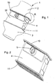
- Fig. 1 shows an embodiment of a heat exchanger according to the invention 1.
- This essentially comprises a first box 2, a first bottom 10, a tube block 4, a second bottom 11 and a second box 3.
- the tube block 4 is surrounded by a cover 32.
- the heat exchanger has a longitudinal direction in which it is flowed through by a charge air flow or an exhaust gas flow.
- Fig. 2 shows an embodiment of the heat exchanger, as it arises after the connection of the tube block 4 with the two floors 10, 11.
- a coolant pipe 5 is arranged, whereby the pipe block 4 coolant can be added or removed.
- Fig. 3 shows a perspective view of a heat exchanger according to the invention, wherein only selected components of the heat exchanger are shown.
- the first floor 10 is connected to both the cover 32 and the first box 2 after assembly of the heat exchanger.
- the boxes 2, 3 have a substantially hood-like shape and in each case an opening on their opposite sides.
- the opening cross-sections are designed such that on the side facing the bottom of the box 2, 3 is a recording in the second gradation 21 of the bottom 10, 11 takes place and on the opposite side to this, the boxes 2, 3 have a substantially circular Cross-section on.
- the boxes 2, 3 are each one-piece components.
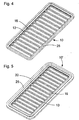
- Fig. 4 shows the rear view of a bottom 10.
- the bottom 10 has a substantially rectangular shape, wherein the corner regions are each rounded.
- passage openings 16 and web-like pipe spacers 13 are arranged alternately transversely to the longitudinal direction of the floor 10, wherein the web-like pipe spacers 13 are regularly spaced apart.
- the through holes 16 receive the plurality of tubes of the tube block (not shown).
- the passage openings 16 have a substantially rectangular shape, wherein the corners may be rounded.
- the profile elevation 25 is formed in the edge region of the bottom 10, which is formed as a circumferential groove.
- Fig. 5 an embodiment of the bottom 10 'according to the present invention is shown.
- the same reference numbers refer to the same Components and features.
- the embodiment of the bottom 10 ' has an additional bottom projection 30 in relation to the first bottom 10, which in particular with a small distance between the coolant connection 5 and the second step 21 in the longitudinal direction of the heat exchanger, welding the bottom 10' to the associated box 2, 3 allows and additionally significantly reduces the distortion of the bottom 10 'and box 2, 3 during welding.
- a section through the bottom 10 for the edge region of the bottom 10 is shown. Inside the bottom 10, a plurality of through openings 16, which alternate with web-like Rohrbeabstandem 13, arranged.
- a skirt 7 is formed, which comprises a first gradation 20 and a second gradation 21, the second gradation 21 being arranged offset in the region of the first gradation 20 to the outside.
- the two steps 20, 21 each form an area on the side facing the box which is essentially planar.
- a profiling increase 25 is formed, which extends from the edge of the bottom 10 to the interior of the bottom 10 substantially to the region of the second step 21 down.
- a bottom recess 22 is formed, which extends into the interior of the bottom 10.
- the bottom recess 22 extends on the side facing away from the box of the bottom 10 to the interior of the bottom 10 towards a second recess 50 which is offset from the bottom recess 22 to the outside and in its edge region, the bottom groove 26 to Recording the cover 32 forms.
- Fig. 7 shows a section through the embodiment of the bottom 10 'for the edge region of the bottom 10'.
- a third step 26 is formed on the side of the bottom 10' facing the box, which is offset outwards relative to the second step 21, whereby a groove is formed between the first step 20 and the third step 26, in which the box extends.
- the upper edge of the first step 20 and the upper edge of the third step 26 are arranged substantially on one level.
- the third step 26 forms outwardly a bottom overhang 30.
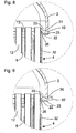
- Fig. 8 shows an enlarged sectional view for the area "A" according to Fig. 1 with a bottom 10.
- the bottom 10 connects the first box 2 and the tube block 4.
- the first box 2 extends into the second step 21.
- a gap is formed between the inside of the first box 2 and the first step 20.
- On the side facing away from the first box 2 of the first bottom 10 a profiling increase 25 is formed, which is a circumferential groove. Between the cover 32 and the profiling elevation 25, a gap in the region of the bottom recess 22 is formed.
- the plurality of tubes 10 in the chamber 6 are received by the through holes in the first floor 10 and the second floor 11 (not shown).
- the tubes 10 are separated in the longitudinal direction of the bottom 10 by web-like pipe spacers 13 from each other.
- the tube block 4 is delimited by the cover 32 from the environment.
- the cover 32 extends in the first floor 10 in the bottom groove 26, whereby it fixes the cover 32 during assembly of the tube block 4 in the first floor 10.
- Fig. 9 shows a heat exchanger according to the invention, which only by the embodiment of the bottom 10 'of the heat exchanger of Fig. 8 different. The following is therefore only compared to the difference Fig. 8 received.
- the second floor 10 ' has a bottom projection 30 in the edge region, which is approximately 5 mm.
- a groove is formed in the region of the second step 21, into which the first case 2 extends. This groove is essentially a circumferential groove.
- the upper edge of the first gradation and the upper edge of the third gradation lie essentially on one level.
Claims (9)
- Echangeur de chaleur, en particulier refroidisseur d'air de suralimentation ou refroidisseur de gaz d'échappement pour un moteur à combustion interne d'un véhicule automobile, ledit échangeur de chaleur comprenant un premier bac (2), un premier fond (10'), un deuxième bac (3) disposé en étant à distance de ce premier bac (2), comprenant un deuxième fond (11) et une multiplicité de tubes (12) au moyen desquels le premier bac (2) et le deuxième bac (3) sont reliés en communiquant fluidiquement, et comprenant une chambre (6) pouvant être traversée par un moyen de refroidissement, chambre qui est disposée entre les deux bacs (2, 3) et à travers laquelle passent plusieurs tubes ou la totalité de ces tubes (12), chambre par laquelle les deux bacs (2, 3) sont reliés en communiquant fluidiquement, et les fonds (10', 11) sont dotés d'une ou de plusieurs ouvertures de passage (16) servant au logement des tubes (12), où au moins un fond (10') présente un rebord (7) s'écartant vers l'extérieur par rapport aux tubes (12), ledit fond étant doté d'un premier étagement (20) et d'un deuxième étagement (21), où le rebord (7) est disposé pratiquement dans la zone de bordure du fond (10'), et le deuxième étagement (21) est disposé, dans la zone du premier étagement (20), en étant décalé vers l'extérieur par rapport au premier étagement (20), où ce fond (10') au moins au nombre de un présente un troisième étagement comportant un bord supérieur, où le bord supérieur se situe dans un plan formé par le premier étagement (20), où au moins un bac (2, 3) ou une partie de paroi (28) de ce même bac (2, 3) s'étend dans le deuxième étagement (21) de ce fond (10'), où le fond (10'), sur son côté placé à l'opposé du bac (2, 3), présente au moins une première élévation de profilage (25), en particulier une première élévation de profilage périphérique (25) située dans la zone de bordure extérieure du fond (10') et, sur un côté d'au moins un fond (10'), placé à l'opposé du bac (2, 3), est formé un évidement (22) se trouvant dans le fond, évidement qui s'étend depuis la première élévation de profilage (25) du fond (10') jusqu'à l'intérieur du fond (10').
- Echangeur de chaleur selon la revendication 1, caractérisé en ce que ce fond (10') au moins au nombre de un forme, à travers le deuxième étagement (21), une rainure située entre le premier étagement (20) et le troisième étagement.
- Echangeur de chaleur selon la revendication 2, caractérisé en ce que le deuxième étagement (21) est une rainure périphérique ou pratiquement périphérique.
- Echangeur de chaleur selon la revendication 1, 2 ou 3, caractérisé en ce qu'il est prévu, pour la délimitation de la chambre (6), au moins une partie couvrante (32), en particulier une tôle de protection, et en ce que le fond (10') présente, sur le côté placé à l'opposé du bac, au moins une rainure (26) se trouvant dans le fond, rainure dans laquelle s'étend une partie de paroi (39) de la partie couvrante (32).
- Echangeur de chaleur selon la revendication 4, caractérisé en ce qu'un intervalle est formé entre la partie couvrante (32) et la première élévation de profilage (25), par l'évidement (22) se trouvant dans le fond.
- Echangeur de chaleur selon l'une quelconque des revendications précédentes, caractérisé en ce qu'au moins un fond (10') présente une partie du fond faisant saillie (30), où cette partie faisant saillie diminue dans son étendue vers l'extérieur, sous l'effet d'un procédé d'assemblage réalisé par continuité de matière, en particulier par soudage, pour l'assemblage d'un fond (10') et d'au moins un bac (2, 3).
- Echangeur de chaleur selon l'une quelconque des revendications précédentes, caractérisé en ce que la partie faisant saillie (30) d'un fond (10') est comprise entre 3 mm et 10 mm, étant de préférence égale à 5 mm.
- Echangeur de chaleur selon l'une quelconque des revendications précédentes, caractérisé en ce qu'au moins un bac (2, 3) est fabriqué en utilisant un procédé d'une technique de moulage.
- Procédé de fabrication d'un échangeur de chaleur (1) selon l'une quelconque des revendications 1 à 8, ledit procédé comprenant les étapes suivantes :- montage du bloc de tubes (4) ;- assemblage, par brasage, des tubes (12) et du fond (10') ;- assemblage, par brasage, de la partie couvrante (32) et du fond (10'), dans la zone de l'évidement (22) se trouvant dans le fond ; étape à laquelle fait suite- l'assemblage, par soudage, du bac (2, 3) et du fond (10').
Applications Claiming Priority (1)
| Application Number | Priority Date | Filing Date | Title |
|---|---|---|---|
| DE102007024630A DE102007024630A1 (de) | 2007-05-24 | 2007-05-24 | Wärmetauscher, insbesondere Ladeluftkühler oder Abgaskühler für eine Brennkraftmaschine eines Kraftfahrzeuges und dessen Herstellungsverfahren |
Publications (3)
| Publication Number | Publication Date |
|---|---|
| EP1995544A2 EP1995544A2 (fr) | 2008-11-26 |
| EP1995544A3 EP1995544A3 (fr) | 2013-08-14 |
| EP1995544B1 true EP1995544B1 (fr) | 2018-07-18 |
Family
ID=39731658
Family Applications (1)
| Application Number | Title | Priority Date | Filing Date |
|---|---|---|---|
| EP08008752.1A Expired - Fee Related EP1995544B1 (fr) | 2007-05-24 | 2008-05-09 | Echangeur thermique, en particulier refroidisseur d'air de suralimentation ou refroidisseur de gaz d'échappement pour un moteur à combustion interne d'un véhicule automobile et son procédé de fabrication |
Country Status (3)
| Country | Link |
|---|---|
| US (1) | US8261815B2 (fr) |
| EP (1) | EP1995544B1 (fr) |
| DE (1) | DE102007024630A1 (fr) |
Families Citing this family (19)
| Publication number | Priority date | Publication date | Assignee | Title |
|---|---|---|---|---|
| BR0215235A (pt) * | 2001-12-21 | 2004-11-16 | Behr Gmbh & Co Kg | Trocador de calor, especialmente para um automóvel |
| EP2137478A2 (fr) * | 2007-04-11 | 2009-12-30 | Behr GmbH & Co. KG | Échangeur de chaleur |
| DE102009053884A1 (de) * | 2009-11-20 | 2011-06-01 | Behr Gmbh & Co. Kg | Saugrohr für einen Verbrennungsmotor |
| DE102010040983A1 (de) * | 2010-09-17 | 2012-03-22 | Behr Gmbh & Co. Kg | Gaskühler |
| EP2458312B1 (fr) | 2010-11-26 | 2018-07-18 | MAHLE International GmbH | Échangeur thermique pour moteur à combustion interne |
| DE102011085479A1 (de) | 2011-10-28 | 2013-05-02 | Behr Gmbh & Co. Kg | Wärmeübertrager |
| FR2984478A1 (fr) * | 2011-12-20 | 2013-06-21 | Valeo Systemes Thermiques | Echangeur de chaleur, ensemble d'un tel echangeur et d'une ou de boites collectrices, module d'admission d'air comprenant un tel ensemble |
| FR2984476B1 (fr) * | 2011-12-20 | 2014-02-28 | Valeo Systemes Thermiques | Echangeur thermique, notamment pour vehicule automobile |
| DE102012214221A1 (de) * | 2012-08-09 | 2014-03-06 | Behr Gmbh & Co. Kg | Wärmeübertrager |
| CN104019691B (zh) | 2012-09-28 | 2017-04-26 | 马勒国际公司 | 热交换器 |
| DE102012217876A1 (de) * | 2012-09-28 | 2014-04-03 | Behr Gmbh & Co. Kg | Wärmeübertrager |
| FR3030709B1 (fr) * | 2014-12-18 | 2019-04-05 | Valeo Systemes Thermiques | Echangeur de chaleur |
| DE102016200456A1 (de) | 2016-01-15 | 2017-07-20 | Mahle International Gmbh | Abgaswärmeübertrager |
| ES2677368B1 (es) * | 2017-01-31 | 2019-05-14 | Valeo Termico Sa | Metodo para la fabricacion de un intercambiador de calor para gases e intercambiador de calor para gases fabricado con el metodo |
| DE102017219433B4 (de) | 2017-10-30 | 2022-08-11 | Hanon Systems | Wärmeübertrager für einen Verbrennungsmotor |
| WO2020104836A1 (fr) | 2018-11-21 | 2020-05-28 | Valeo North America, Inc. | Refroidisseur d'air de charge |
| DE102019112194A1 (de) * | 2019-05-09 | 2020-11-12 | Mahle International Gmbh | Wärmeübertrager |
| FR3108395B1 (fr) * | 2020-03-20 | 2022-11-11 | Valeo Systemes Thermiques | Echangeur thermique pour véhicule automobile |
| EP4342624A1 (fr) * | 2022-09-20 | 2024-03-27 | Alfa Laval Vicarb | Module d'échangeur de chaleur, procédé de soudage d'échangeur de chaleur et ensemble échangeur de chaleur |
Family Cites Families (8)
| Publication number | Priority date | Publication date | Assignee | Title |
|---|---|---|---|---|
| JPS57132989U (fr) * | 1981-02-04 | 1982-08-19 | ||
| US4485867A (en) * | 1982-02-08 | 1984-12-04 | Ex-Cell-O Corporation | Heat exchanger |
| FR2584488A1 (fr) * | 1985-07-03 | 1987-01-09 | Chausson Usines Sa | Procede pour la liaison d'au moins une plaque collectrice et d'une boite a eau sur les tubes d'un echangeur de chaleur et echangeur de chaleur en faisant application. |
| DE4436027A1 (de) * | 1994-10-08 | 1996-04-11 | Behr Gmbh & Co | Verfahren zum Herstellen einer dichten Verbindung |
| FR2805036B1 (fr) * | 2000-02-10 | 2002-06-14 | Valeo Thermique Moteur Sa | Echangeur de chaleur avec joint d'etancheite ameliore, en particulier pour vehicule automobile |
| DE10233407B4 (de) * | 2001-07-26 | 2016-02-18 | Denso Corporation | Abgaswärmeaustauscher |
| DE10316756A1 (de) * | 2003-04-10 | 2004-10-28 | Behr Gmbh & Co. Kg | Wärmeübertrager, insbesondere Ladeluftkühler für Kraftfahrzeuge |
| DE102006043526A1 (de) | 2005-09-12 | 2007-04-05 | Behr Gmbh & Co. Kg | Wärmetauscher, inbesondere Ladeluftkühler oder Abgaskühler für eine Brennkraftmaschine eines Kraftfahrzeuges |
-
2007
- 2007-05-24 DE DE102007024630A patent/DE102007024630A1/de not_active Withdrawn
-
2008
- 2008-05-09 EP EP08008752.1A patent/EP1995544B1/fr not_active Expired - Fee Related
- 2008-05-23 US US12/126,299 patent/US8261815B2/en active Active
Non-Patent Citations (1)
| Title |
|---|
| None * |
Also Published As
| Publication number | Publication date |
|---|---|
| US20080289833A1 (en) | 2008-11-27 |
| EP1995544A2 (fr) | 2008-11-26 |
| US8261815B2 (en) | 2012-09-11 |
| EP1995544A3 (fr) | 2013-08-14 |
| DE102007024630A1 (de) | 2008-11-27 |
Similar Documents
| Publication | Publication Date | Title |
|---|---|---|
| EP1995544B1 (fr) | Echangeur thermique, en particulier refroidisseur d'air de suralimentation ou refroidisseur de gaz d'échappement pour un moteur à combustion interne d'un véhicule automobile et son procédé de fabrication | |
| DE10231973B4 (de) | Abgaswärmetauscher | |
| EP1929233B1 (fr) | Refroidisseur d'air de suralimentation ou refroidisseur de gaz d'echappement pour un moteur a combustion interne d'un vehicule automobile | |
| EP1929231B1 (fr) | Échangeur de chaleur, notamment échangeur de chaleur de gaz d'échappement de véhicules automobiles | |
| DE69720506T2 (de) | Wärmetauscher | |
| DE69823384T2 (de) | Wärmetauscher | |
| DE60031932T2 (de) | Mehrfachwärmetauscher mit zwei Kernen | |
| EP1616143B1 (fr) | Echangeur thermique, en particulier refroidisseur d'air de suralimentation pour vehicules automobiles | |
| DE102007049665A1 (de) | Wärmeaustauscher | |
| EP1398589B1 (fr) | Radiateur pour liquide de refroidissement | |
| DE10392626T5 (de) | Wärmeleitrohr und Wärmetauscher mit einem solchen Wärmeleitrohr | |
| EP1279805A2 (fr) | Refroidisseur de l'air de charge aéroréfrigérée | |
| EP1518043B1 (fr) | Echangeur thermique pour gaz d'echappement et procede de fabrication associe | |
| DE10215091A1 (de) | Spiralförmige Rippe/Röhre als Wärmeaustauscher | |
| DE102008002430A1 (de) | Abgaswärmetauscher mit schwingungsgedämpftem Tauscher-Rohrbündel | |
| DE102005007591A1 (de) | Wärmetauscher | |
| DE102007058149A1 (de) | Wärmetauscher, Anordnung und Verfahren zur Herstellung eines Wärmetauschers | |
| DE19906063A1 (de) | Wärmetauscher und Verfahren zur Herstellung eines Sammel/Verteiler-Behälters | |
| DE112010002744T5 (de) | Wärmetauscher mit Gussgehäuse und Verfahren zur Herstellung desselben | |
| DE102008002746A1 (de) | Wärmetauscher für den Abgasstrang eines Kraftfahrzeugs, Verfahren zur Herstellung eines Wärmetauschers sowie Montagewerkzeug hierzu | |
| EP2863157B1 (fr) | Échangeur de chaleur | |
| DE112017006549B4 (de) | Ladeluftkühler | |
| DE102008046024A1 (de) | Wärmeaustauscher | |
| DE102006043526A1 (de) | Wärmetauscher, inbesondere Ladeluftkühler oder Abgaskühler für eine Brennkraftmaschine eines Kraftfahrzeuges | |
| EP1376043B1 (fr) | Echangeur de chaleur avec diffuseur |
Legal Events
| Date | Code | Title | Description |
|---|---|---|---|
| PUAI | Public reference made under article 153(3) epc to a published international application that has entered the european phase |
Free format text: ORIGINAL CODE: 0009012 |
|
| AK | Designated contracting states |
Kind code of ref document: A2 Designated state(s): AT BE BG CH CY CZ DE DK EE ES FI FR GB GR HR HU IE IS IT LI LT LU LV MC MT NL NO PL PT RO SE SI SK TR |
|
| AX | Request for extension of the european patent |
Extension state: AL BA MK RS |
|
| PUAL | Search report despatched |
Free format text: ORIGINAL CODE: 0009013 |
|
| AK | Designated contracting states |
Kind code of ref document: A3 Designated state(s): AT BE BG CH CY CZ DE DK EE ES FI FR GB GR HR HU IE IS IT LI LT LU LV MC MT NL NO PL PT RO SE SI SK TR |
|
| AX | Request for extension of the european patent |
Extension state: AL BA MK RS |
|
| RIC1 | Information provided on ipc code assigned before grant |
Ipc: F28F 9/02 20060101ALI20130708BHEP Ipc: F02M 25/07 20060101ALI20130708BHEP Ipc: F28D 7/16 20060101AFI20130708BHEP Ipc: F02B 29/04 20060101ALI20130708BHEP |
|
| 17P | Request for examination filed |
Effective date: 20140214 |
|
| RBV | Designated contracting states (corrected) |
Designated state(s): AT BE BG CH CY CZ DE DK EE ES FI FR GB GR HR HU IE IS IT LI LT LU LV MC MT NL NO PL PT RO SE SI SK TR |
|
| AKX | Designation fees paid |
Designated state(s): DE FR |
|
| RAP1 | Party data changed (applicant data changed or rights of an application transferred) |
Owner name: MAHLE BEHR GMBH & CO. KG |
|
| 17Q | First examination report despatched |
Effective date: 20170102 |
|
| GRAP | Despatch of communication of intention to grant a patent |
Free format text: ORIGINAL CODE: EPIDOSNIGR1 |
|
| RIC1 | Information provided on ipc code assigned before grant |
Ipc: F02B 29/04 20060101ALI20180205BHEP Ipc: F28F 9/02 20060101ALI20180205BHEP Ipc: F28D 7/16 20060101AFI20180205BHEP |
|
| INTG | Intention to grant announced |
Effective date: 20180301 |
|
| GRAS | Grant fee paid |
Free format text: ORIGINAL CODE: EPIDOSNIGR3 |
|
| GRAJ | Information related to disapproval of communication of intention to grant by the applicant or resumption of examination proceedings by the epo deleted |
Free format text: ORIGINAL CODE: EPIDOSDIGR1 |
|
| GRAL | Information related to payment of fee for publishing/printing deleted |
Free format text: ORIGINAL CODE: EPIDOSDIGR3 |
|
| GRAR | Information related to intention to grant a patent recorded |
Free format text: ORIGINAL CODE: EPIDOSNIGR71 |
|
| GRAA | (expected) grant |
Free format text: ORIGINAL CODE: 0009210 |
|
| INTC | Intention to grant announced (deleted) | ||
| RIN1 | Information on inventor provided before grant (corrected) |
Inventor name: SCHIENEMANN, MARK Inventor name: MOLDOVAN, FLORIN |
|
| AK | Designated contracting states |
Kind code of ref document: B1 Designated state(s): DE FR |
|
| INTG | Intention to grant announced |
Effective date: 20180608 |
|
| REG | Reference to a national code |
Ref country code: DE Ref legal event code: R096 Ref document number: 502008016187 Country of ref document: DE |
|
| REG | Reference to a national code |
Ref country code: DE Ref legal event code: R097 Ref document number: 502008016187 Country of ref document: DE |
|
| PLBE | No opposition filed within time limit |
Free format text: ORIGINAL CODE: 0009261 |
|
| STAA | Information on the status of an ep patent application or granted ep patent |
Free format text: STATUS: NO OPPOSITION FILED WITHIN TIME LIMIT |
|
| 26N | No opposition filed |
Effective date: 20190423 |
|
| PGFP | Annual fee paid to national office [announced via postgrant information from national office to epo] |
Ref country code: FR Payment date: 20200523 Year of fee payment: 13 |
|
| PGFP | Annual fee paid to national office [announced via postgrant information from national office to epo] |
Ref country code: DE Payment date: 20200721 Year of fee payment: 13 |
|
| REG | Reference to a national code |
Ref country code: DE Ref legal event code: R119 Ref document number: 502008016187 Country of ref document: DE |
|
| PG25 | Lapsed in a contracting state [announced via postgrant information from national office to epo] |
Ref country code: DE Free format text: LAPSE BECAUSE OF NON-PAYMENT OF DUE FEES Effective date: 20211201 |
|
| PG25 | Lapsed in a contracting state [announced via postgrant information from national office to epo] |
Ref country code: FR Free format text: LAPSE BECAUSE OF NON-PAYMENT OF DUE FEES Effective date: 20210531 |