EP2138656A2 - External door handle, in particular for vehicles - Google Patents
External door handle, in particular for vehicles Download PDFInfo
- Publication number
- EP2138656A2 EP2138656A2 EP20090075262 EP09075262A EP2138656A2 EP 2138656 A2 EP2138656 A2 EP 2138656A2 EP 20090075262 EP20090075262 EP 20090075262 EP 09075262 A EP09075262 A EP 09075262A EP 2138656 A2 EP2138656 A2 EP 2138656A2
- Authority
- EP
- European Patent Office
- Prior art keywords
- locking member
- door handle
- outside door
- locking
- projections
- Prior art date
- Legal status (The legal status is an assumption and is not a legal conclusion. Google has not performed a legal analysis and makes no representation as to the accuracy of the status listed.)
- Granted
Links
Images


Classifications
-
- E—FIXED CONSTRUCTIONS
- E05—LOCKS; KEYS; WINDOW OR DOOR FITTINGS; SAFES
- E05B—LOCKS; ACCESSORIES THEREFOR; HANDCUFFS
- E05B77/00—Vehicle locks characterised by special functions or purposes
- E05B77/02—Vehicle locks characterised by special functions or purposes for accident situations
- E05B77/04—Preventing unwanted lock actuation, e.g. unlatching, at the moment of collision
- E05B77/06—Preventing unwanted lock actuation, e.g. unlatching, at the moment of collision by means of inertial forces
-
- E—FIXED CONSTRUCTIONS
- E05—LOCKS; KEYS; WINDOW OR DOOR FITTINGS; SAFES
- E05B—LOCKS; ACCESSORIES THEREFOR; HANDCUFFS
- E05B85/00—Details of vehicle locks not provided for in groups E05B77/00 - E05B83/00
- E05B85/10—Handles
- E05B85/14—Handles pivoted about an axis parallel to the wing
- E05B85/16—Handles pivoted about an axis parallel to the wing a longitudinal grip part being pivoted at one end about an axis perpendicular to the longitudinal axis of the grip part
-
- Y—GENERAL TAGGING OF NEW TECHNOLOGICAL DEVELOPMENTS; GENERAL TAGGING OF CROSS-SECTIONAL TECHNOLOGIES SPANNING OVER SEVERAL SECTIONS OF THE IPC; TECHNICAL SUBJECTS COVERED BY FORMER USPC CROSS-REFERENCE ART COLLECTIONS [XRACs] AND DIGESTS
- Y10—TECHNICAL SUBJECTS COVERED BY FORMER USPC
- Y10T—TECHNICAL SUBJECTS COVERED BY FORMER US CLASSIFICATION
- Y10T292/00—Closure fasteners
- Y10T292/57—Operators with knobs or handles
Definitions
- the invention relates to an outside door handle, in particular for vehicles specified in the preamble of claim 1.
- Such outside door handles find a variety of uses. In the event of a crash, in particular with a strong side impact, it is necessary to prevent the handles of the vehicle doors from pivoting outwards as a result of the released forces and thus opening the vehicle doors. As a result, there would be a risk that the vehicle occupants or objects located in the vehicle will be ejected from the vehicle.
- pivotable locking members are proposed, which are deflected due to the inertia of their mass, before it comes to a deflection of the handle and then block an effective operation of the handle, thus avoiding unwanted opening of the vehicle doors.
- Such a mass barrier describes, for example, the EP 1 050 640 A2 ,
- an outside door handle for vehicles is described, which has a pendulum-like locking member.
- this locking member is deflected, thereby preventing effective operation of the handle.
- a disadvantage of this Arrangement is, however, that for the various doors in the vehicle, such as driver and passenger door, various devices must be provided because the blocking of the movement of the outside door handle takes place only in one direction.
- the locking member can only prevent unintentional opening of the door in accidents with substantially the same Crashraum. If the crash occurs from a direction opposite to the optimum direction to which the device has been designed, inadvertent opening of the door, for example due to the vibration of the handle caused by the crash, can not be prevented.
- the object of the invention is therefore to provide an outside door handle of the type specified, which can be used on all doors of the vehicle and which prevents accidental opening of the vehicle door by a crash from different directions.
- This object is solved by the characterizing features of claim 1, which has the following special significance.
- the locking member has two locking positions. In a crash from a first direction, the locking member then passes through the deflection caused by the crash due to the inertia of its mass in a first locking position. However, if a crash occurs from a second direction, which is at least partially opposite to the first crash direction approximately, the locking member is in another Directed deflected and thus enters a second locked position. This has the advantage that unintentional opening of the door is avoided, regardless of the direction from which the crash occurs. Inadvertent actuation of the handle and an associated opening of the door by the vibrations caused by the impact of the crash are prevented.
- the handle is possible to provide an outside door handle, which can be mounted on all doors, in particular on both sides of the vehicle and which nevertheless meets the requirements for crash safety. This is cheaper to manufacture and also saves on warehousing costs.
- the locking member locks in the present invention, the handle Swissschaltun a blocking lever. This is guided in a slotted guide and moved in the normal operation of the handle. In the event of a crash, however, this movement of the blocking lever is prevented by the locking member, whereby the handle can not be moved and the door does not open unintentionally.
- the interposition of the blocking lever is a good point of attack for the locking member in its locked position.
- the link guide ensures a simple and error-prone actuation and movement of the blocking lever.
- the locking member is moved to a small extent. Since the locking member is naturally rarely used, it could otherwise happen that this gets stuck or jammed over time or that the surfaces corrode. In such a case, a secure operation of the locking member is no longer guaranteed in a then occurring crash case. Due to the comparatively frequent easy operation of the locking member of this setting is avoided. The locking member is thus operational over the entire life of the vehicle.
- the blocking lever is connected in a preferred embodiment with an element which is also moved in the operation of the handle, a so-called Loselement. It is particularly favorable for fixing the Blocking lever that Loselement to use, which also passes on the movement of the handle to the lock and thereby enabling the operation of the handle opening the door. The passing of the movement to the castle is often done by means of a Bowden cable or with the help of a rod. However, it is also possible to provide one or more mass balance weights, which provide in the event of a crash for mass balance. Since the mass weights are usually elements that are moved along with the actuation of the handle, they also offer themselves as a loose element to which the blocking lever can be fastened.
- the locking member should be arranged on a fixed element, which does not move when the handle is operated.
- a bearing bracket or a handle support offer a bearing bracket or a handle support.
- the locking member is spring-loaded, wherein the spring load ensures that the locking member normally remains in its release position. This avoids, on the one hand, that the locking member is deflected by normal movements of the vehicle, for example when driving around a curve, from its release position in one of its locking positions and as an actuation of the handle and thus opening the door is no longer possible. It is also important that after a successful crash outside people can open the vehicle door, for example, to free injured vehicle occupants or children from the vehicle. Therefore, the spring load also conveniently ensures that after the crash and after the decay of the vibrations caused by this crash, the locking member is transferred back to its release position, so that the doors can be opened.
- each one of these projections in one of the two locking positions with a Counter projection occurs in operative connection.
- the projections and counter projections may be configured differently, as will be shown later.
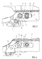
- Fig. 1 shows the outside door handle according to the invention with the handle 10.
- a mass balance weight 12 is provided and also serves as a Loselement 11.
- At mass balance weight 12 of the blocking lever 40 is rotatably articulated.
- the other side of the blocking lever 40 is located in a mounted on the bearing bracket 14 slotted guide 41.
- Also arranged on the bearing bracket 14 is the locking member 20, which is in its release position 21.
- Below the locking member 20, the spring 27 is arranged, which has the tendency to keep the locking member 20 in its release 21.
- the spring 27 is designed so that it counteracts deflections of the locking member 20 in both directions.
- the locking member 20 has two stops 28.1 and 28.2. In each of its locking positions 22.1, 22.2, the locking member 20 enters with one of its stops 28.1, 28.2 with a counter-stop 43 in operative connection, which will be shown in more detail later.
- the locking member 20 itself is approximately Y-shaped 50.
- the stops 28.1, 28.2 are arranged at the ends 52 of the two Y-legs 51.
- FIG. 4 again show the locking member 20 in its release position 21. Since in the illustration in Fig. 4 the covers were removed, it can be seen clearly how the blocking lever 40, which is moved in a normal operation of the handle 10, abuts the locking member 20, in particular to the ends 52 of the Y-leg 51 and thus causes the slight movement of the locking member 20 Protecting this from jamming.
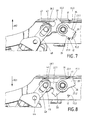
- the locking member 20 is shown in its locking positions 22.1, 22.2.
- the direction 30.1, 30.2 of a crash which has led to the deflection of the blocking member 20 and thus to the illustrated blocking position 22.1, 22.2 is shown.
- the crash does not have to be from exactly the direction shown to result in the result shown. It is quite sufficient if at least a part of the direction of movement of the crash points in the illustrated direction 30.1, 30.2.
- the function of the stopper 42 is clearly visible. Characterized in that the blocking lever 40 is rotatably mounted on the Loselement 11 and is guided on the fixed element 13 in a link 41, the stopper 42 additionally ensures that the blocking lever 40 between the stop 28.1, 28.2 of the locking member 20 and the stopper 42 is wedged , so that a movement of the blocking lever 40 and thus also the handle 10 in the event of a crash is no longer possible. The forces acting on the handle 10 from the crash forces are thus absorbed by the bearing 44 of the locking lever 40 on the Loselement 11 and the stopper 42 with the participation of the locking member 20. Of course, embodiments without stoppers 42 are possible. There, the forces caused by the crash forces from the sliding block 45 of the slotted guide 41 and the bearing 44 of the locking lever 40 are then added.
- FIGS. 7 and 8 This is also from the FIGS. 7 and 8 recognizable, in which also the locking member 20 is shown in its two locking positions 22.1, 22.2.
- lugs 17 are still provided, which form the mating counter-projections 15.1, 15.2.
- the interaction of the projections 23.1, 23.2 and the counter-projections 15.1, 15.2 is from the FIGS. 7 and 8 clearly recognizable.
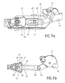
- FIGS. 9a to 14 show a third preferred embodiment of the invention.
- the locking member 20 which is in its release position 21.
- the blocking lever 40 is freely movable in its slotted guide 41.
- the movement of the blocking lever 40 is purely translational here.
- the handle 10, not shown here is in the in the Fig. 9a and 9b shown release position 21 is not actuated.
- the blocking lever 40 projects with its end 47 and in particular with the attached thereto cam 46 in a recess 24 between the legs 51 of the Y-shaped 50 locking member 20. In this position, the cam 46 is aligned with the opening 29 of the recess 24 on the locking member 20th and the stops 28.1, 28.2 are provided in this recess 24.
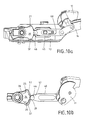
- the first and second barrier layers 22.1, 22.2 are in the Fig. 12a and 12b or 11 a and 11 b shown.
- the arranged at the end 47 of the blocking lever 40 cam 46 is no longer aligned with the opening 29 of the recess 24. Rather, the cam 46 is trapped in the recess 24.
- the sides 25 of the recess 24 serve both as projections 23.1, 23.2 and as stops 28.1, 28.2.
- the counter-projections 15.1, 15.2 are realized by the cam 46 of the blocking lever 40.
- FIGS. 13 and 14 directed. These again give an overview of the arrangement of the most important components of the third embodiment; especially in Fig. 14 the interaction of locking member 20, blocking lever 40 and mass balance weight 12 is clear. It is thus clearly evident that unintentional and accidental actuation of the handle 10 is not possible in the first blocking position 22.1 shown there.
- the embodiments shown here are merely exemplary implementations of the invention. This is not limited to this. Rather, multiple modifications and variations are possible.
- the locking member may have only one Y-leg or configured differently. It is also possible that the locking member has only a single locking position or locks only in a Crashraum.
Landscapes
- Lock And Its Accessories (AREA)
Abstract
Description
Die Erfindung betrifft einen Türaußengriff, insbesondere für Fahrzeuge der im Oberbegriff des Anspruchs 1 angegebenen Art. Solche Türaußengriffe finden vielfältig Verwendung. Bei einem Crash, insbesondere mit starkem Seitenaufprall gilt es zu verhindern, dass sich die Handhaben der Fahrzeugtüren durch die freiwerdenden Kräfte nach außen verschwenken und somit die Fahrzeugtüren öffnen. Hierdurch würde die Gefahr bestehen, dass die Fahrzeuginsassen oder im Fahrzeug befindliche Gegenstände aus dem Fahrzeug herausgeschleudert werden. Im Stand der Technik werden daher schwenkbare Sperrglieder vorgeschlagen, welche aufgrund der Trägheit ihrer Masse ausgelenkt werden, bevor es zu einer Auslenkung der Handhabe kommt und die dann eine wirksame Betätigung der Handhabe blockieren und so ein unerwünschtes Öffnen der Fahrzeugtüren vermeiden.The invention relates to an outside door handle, in particular for vehicles specified in the preamble of
Eine solche Massensperre beschreibt beispielsweise die
Ein ähnliches Problem ergibt sich auch bei dem in der
Aufgabe der Erfindung ist es daher, einen Türaußengriff der eingangs angegebenen Art zu schaffen, welcher an allen Türen des Fahrzeugs eingesetzt werden kann und welcher ein ungewolltes Öffnen der Fahrzeugtür durch einen Crash aus den unterschiedlichsten Richtungen verhindert. Diese Aufgabe wird durch die kennzeichnenden Merkmale des Anspruchs 1 gelöst, denen folgende besondere Bedeutung zukommt.The object of the invention is therefore to provide an outside door handle of the type specified, which can be used on all doors of the vehicle and which prevents accidental opening of the vehicle door by a crash from different directions. This object is solved by the characterizing features of
Das Sperrglied verfügt über zwei Sperrlagen. Bei einem Crash aus einer ersten Richtung gelangt das Sperrglied dann durch die durch den Crash verursachte Auslenkung aufgrund der Trägheit seiner Masse in eine erste Sperrlage. Erfolgt jedoch ein Crash aus einer zweiten Richtung, welche zumindest teilweise der ersten Crashrichtung in etwa entgegengesetzt ist, wird das Sperrglied in eine andere Richtung ausgelenkt und gelangt so in eine zweite Sperrlage. Dies hat den Vorteil, dass ein unbeabsichtigtes Öffnen der Tür vermieden wird, unabhängig von der Richtung, aus der der Crash erfolgt. Auch ein unbeabsichtigtes Betätigen der Handhabe und ein damit verbundenes Öffnen der Tür durch die durch den Aufprall des Crashes verursachten Schwingungen werden verhindert. Außerdem ist es möglich, einen Türaußengriff vorzusehen, welcher an allen Türen, insbesondere auf beiden Seiten des Fahrzeugs montiert werden kann und welcher trotzdem den Anforderungen an die Crashsicherheit gerecht wird. Dies ist kostengünstiger in der Herstellung und spart auch Kosten für die Lagerhaltung. Das Sperrglied sperrt bei der vorliegenden Erfindung die Handhabe unter Zwischenschaltun eines Blockierhebels. Dieser wird in einer Kulissenführung geführt und bei der normalen Betätigung der Handhabe mitbewegt. Im Crashfall wird jedoch gerade diese Bewegung des Blockierhebels vom Sperrglied verhindert, wodurch auch die Handhabe nicht bewegt werden kann und die Tür sich nicht ungewollt öffnet. Durch die Zwischenschaltung des Blockierhebels ist ein guter Angriffspunkt für das Sperrglied in seiner Sperrlage gegeben. Die Kulissenführung sorgt für eine einfache und fehlerunanfällige Betätigungs- und Bewegungsmöglichkeit des Blockierhebels.The locking member has two locking positions. In a crash from a first direction, the locking member then passes through the deflection caused by the crash due to the inertia of its mass in a first locking position. However, if a crash occurs from a second direction, which is at least partially opposite to the first crash direction approximately, the locking member is in another Directed deflected and thus enters a second locked position. This has the advantage that unintentional opening of the door is avoided, regardless of the direction from which the crash occurs. Inadvertent actuation of the handle and an associated opening of the door by the vibrations caused by the impact of the crash are prevented. In addition, it is possible to provide an outside door handle, which can be mounted on all doors, in particular on both sides of the vehicle and which nevertheless meets the requirements for crash safety. This is cheaper to manufacture and also saves on warehousing costs. The locking member locks in the present invention, the handle Zwischenschaltun a blocking lever. This is guided in a slotted guide and moved in the normal operation of the handle. In the event of a crash, however, this movement of the blocking lever is prevented by the locking member, whereby the handle can not be moved and the door does not open unintentionally. The interposition of the blocking lever is a good point of attack for the locking member in its locked position. The link guide ensures a simple and error-prone actuation and movement of the blocking lever.
Besonders vorteilhaft ist es, wenn man vorsieht, dass bei der normalen Betätigung der Handhabe das Sperrglied in einem geringen Maße mitbewegt wird. Da das Sperrglied naturgemäß selten zum Einsatz kommt, könnte es anderenfalls passieren, dass sich dieses mit der Zeit festsetzt bzw. verklemmt oder dass die Oberflächen korrodieren. In einem solchen Fall ist eine sichere Funktion des Sperrgliedes in einem dann erfolgenden Crashfall nicht mehr gewährleistet. Durch die vergleichsweise häufige leichte Betätigung des Sperrgliedes wird dieses Festsetzen vermieden. Das Sperrglied ist somit über die gesamte Lebensdauer des Fahrzeuges einsatzfähig.It is particularly advantageous if it is provided that in the normal operation of the handle, the locking member is moved to a small extent. Since the locking member is naturally rarely used, it could otherwise happen that this gets stuck or jammed over time or that the surfaces corrode. In such a case, a secure operation of the locking member is no longer guaranteed in a then occurring crash case. Due to the comparatively frequent easy operation of the locking member of this setting is avoided. The locking member is thus operational over the entire life of the vehicle.
Der Blockierhebel ist in einem bevorzugten Ausführungsbeispiel mit einem Element verbunden, welches bei der Betätigung der Handhabe ebenfalls bewegt wird, einem sogenannten Loselement. Besonders günstig ist es, zur Befestigung des Blockierhebels dasjenige Loselement zu verwenden, welches auch die Bewegung der Handhabe an das Schloss weitergibt und wodurch überhaupt die Betätigung der Handhabe ein Öffnen der Tür ermöglicht. Die Weitergabe der Bewegung an das Schloss erfolgt häufig mittels eines Bowdenzuges oder auch mit Hilfe einer Stange. Es ist jedoch auch möglich, einen oder mehrere Massenausgleichsgewichte vorzusehen, welche im Crashfall für den Massenausgleich sorgen. Da es sich bei den Massenausgewichten üblicherweise um Elemente handelt, welche bei der Betätigung der Handhabe mitbewegt werden, bieten sich diese auch als Loselement an, an welchem der Blockierhebel befestigbar ist.The blocking lever is connected in a preferred embodiment with an element which is also moved in the operation of the handle, a so-called Loselement. It is particularly favorable for fixing the Blocking lever that Loselement to use, which also passes on the movement of the handle to the lock and thereby enabling the operation of the handle opening the door. The passing of the movement to the castle is often done by means of a Bowden cable or with the help of a rod. However, it is also possible to provide one or more mass balance weights, which provide in the event of a crash for mass balance. Since the mass weights are usually elements that are moved along with the actuation of the handle, they also offer themselves as a loose element to which the blocking lever can be fastened.
Im Gegensatz dazu sollte das Sperrglied an einem fixen Element, welches sich bei der Betätigung der Handhabe nicht mitbewegt, angeordnet werden. Hierbei bieten sich beispielsweise ein Lagerbügel oder ein Griffträger an. Diese Bauteile sind bei einem Türaußengriff in der Regel vorhanden, da sie dazu dienen, den Türgriff in der Tür zu befestigen und zu lagern.In contrast, the locking member should be arranged on a fixed element, which does not move when the handle is operated. Here, for example, offer a bearing bracket or a handle support. These components are usually present in an outside door handle, as they serve to secure the door handle in the door and store.
In einer bevorzugten Ausführungsform ist das Sperrglied federbelastet, wobei die Federbelastung dafür sorgt, dass das Sperrglied im Normalfall in seiner Freigabelage verbleibt. Hierdurch wird einerseits vermieden, dass das Sperrglied durch normale Bewegungen des Fahrzeuges, beispielsweise beim Fahren um eine Kurve, aus seiner Freigabelage in eine seiner Sperrlagen ausgelenkt wird und so eine Betätigung der Handhabe und somit ein Öffnen der Tür nicht mehr möglich ist. Ebenfalls ist es wichtig, dass nach einem erfolgten Crash Personen von außen die Fahrzeugtür öffnen können, um beispielsweise verletzte Fahrzeuginsassen oder Kinder aus dem Fahrzeug zu befreien. Die Federbelastung sorgt daher auch günstigerweise dafür, dass nach erfolgtem Crash und nach dem Abklingen der durch diesen Crash hervorgerufenen Vibrationen das Sperrglied wieder in seine Freigabelage überführt wird, so dass die Türen geöffnet werden können.In a preferred embodiment, the locking member is spring-loaded, wherein the spring load ensures that the locking member normally remains in its release position. This avoids, on the one hand, that the locking member is deflected by normal movements of the vehicle, for example when driving around a curve, from its release position in one of its locking positions and as an actuation of the handle and thus opening the door is no longer possible. It is also important that after a successful crash outside people can open the vehicle door, for example, to free injured vehicle occupants or children from the vehicle. Therefore, the spring load also conveniently ensures that after the crash and after the decay of the vibrations caused by this crash, the locking member is transferred back to its release position, so that the doors can be opened.
Empfehlenswerterweise sind am Sperrglied zwei Vorsprünge vorgesehen, wobei jeweils einer dieser Vorsprünge in einer der beiden Sperrlagen mit einem Gegenvorsprung in Wirkverbindung tritt. Hierdurch kann man verhindern, dass das Sperrglied im Crashfall zu weit ausgelenkt wird und somit die unerwünschte Betätigung der Handhabe nicht vermieden wird. Die Vorsprünge und Gegenvorsprünge können unterschiedlich ausgestaltet sein, wie noch später gezeigt werden wird.It is recommended that two projections are provided on the locking member, wherein each one of these projections in one of the two locking positions with a Counter projection occurs in operative connection. In this way, it is possible to prevent the locking member from being deflected too far in the event of a crash, and thus the undesired actuation of the handle is not avoided. The projections and counter projections may be configured differently, as will be shown later.
Weitere Ausführungsformen und Vorteile der Erfindung ergeben sich aus der nachfolgenden Beschreibung, den Unteransprüchen und den Zeichnungen. In den Zeichnungen ist der Erfindungsgegenstand in drei Ausführungsformen dargestellt.Further embodiments and advantages of the invention will become apparent from the following description, the subclaims and the drawings. In the drawings, the subject invention is shown in three embodiments.
Es zeigen:
- Fig. 1
- einen erfindungsgemäßen Türaußengriff mit Handhabe in perspektivischer Darstellung,
- Fig. 2
- einen vergrößerten Ausschnitt aus
Fig. 1 , - Fig. 3
- den Türaußengriff aus
Fig. 1 und Draufsicht in Freigabelage, - Fig. 4
- die Darstellung von
Fig. 3 mit entfernten Abdeckungen, - Fig. 5
- eine Darstellung analog zu
Fig. 4 , jedoch in der zweiten Sperrlage, - Fig. 6
- eine Darstellung gemäß
Fig. 5 , jedoch in der ersten Sperrlage, - Fig. 7
- eine Darstellung gemäß
Fig. 5 vor einem zweiten Ausführungsbeispiel, - Fig. 8
- eine Darstellung gemäß
Fig. 6 von dem Ausführungsbeispiel ausFig. 7 . - Fig. 9a
- eine weitere Ausführungsform des erfindungsgemäßen Türaußengriffes in Freigabelage
- Fig. 9b
- der Türaußengriff gemäß
Fig. 9a in einer anderen Ansicht - Fig. 10a
- der Türaußengriff gemäß
Fig. 9a bei Betätigung der Handhabe - Fig. 10b
- der Türaußengriff gemäß
Fig. 10a in Ansicht gemäßFig. 9b - Fig. 11a
- der Türaußengriff gemäß
Fig. 9a in der zweiten Sperrlage - Fig. 11b
- der Türaußengriff gemäß
Fig. 11 a in Ansicht gemäßFig. 9b - Fig. 12a
- der Türaußengriff gemäß
Fig. 9a in der ersten Sperrlage - Fig. 12b
- der Türaußengriff gemäß
Fig. 12a in Ansicht gemäßFig. 9b - Fig. 13
- der Türaußengriff gemäß
Fig. 9a in seiner ersten Sperrlage, perspektivisch - Fig. 14
- der Türaußengriff gemäß
Fig. 13 , von anderer Perspektive, Weg der Kraftübertragung
- Fig. 1
- an outside door handle according to the invention with handle in perspective view,
- Fig. 2
- an enlarged section
Fig. 1 . - Fig. 3
- the outside door handle
Fig. 1 and overhead view in release position, - Fig. 4
- the representation of
Fig. 3 with removed covers, - Fig. 5
- a representation analogous to
Fig. 4 but in the second locked position, - Fig. 6
- a representation according to
Fig. 5 but in the first locked position, - Fig. 7
- a representation according to
Fig. 5 before a second embodiment, - Fig. 8
- a representation according to
Fig. 6 from the embodimentFig. 7 , - Fig. 9a
- a further embodiment of the outside door handle according to the invention in the release position
- Fig. 9b
- the outside door handle according to
Fig. 9a in a different view - Fig. 10a
- the outside door handle according to
Fig. 9a upon actuation of the handle - Fig. 10b
- the outside door handle according to
Fig. 10a in view according toFig. 9b - Fig. 11a
- the outside door handle according to
Fig. 9a in the second locked position - Fig. 11b
- the outside door handle according to
Fig. 11 a in view according toFig. 9b - Fig. 12a
- the outside door handle according to
Fig. 9a in the first locked position - Fig. 12b
- the outside door handle according to
Fig. 12a in view according toFig. 9b - Fig. 13
- the outside door handle according to
Fig. 9a in its first locked position, in perspective - Fig. 14
- the outside door handle according to
Fig. 13 , from another perspective, way of power transmission
Etwas detaillierter ist dies aus
Auch
In den
Es zeigt sich, dass in jeder der Sperrlagen 22.1, 22.2 einer der Anschläge 28.1, 28.2 des Sperrgliedes 20 mit einem Gegenanschlag 43 am Blockierhebel 40 in Wirkverbindung steht. Im dargestellten Ausführungsbeispiel gibt es nur einen Gegenanschlag 43 für beide Anschläge 28.1, 28.2. Es kann selbstverständlich auch nur einen Anschlag 28.1, 28.2 und/oder zwei Gegenanschläge 43 geben, je nach Ausführung der Erfindung.It turns out that in each of the locking positions 22.1, 22.2 one of the stops 28.1, 28.2 of the locking
Ebenfalls erkennt man die Ausnehmung 24 am Sperrglied 20 sowie den Zapfen 16, der am Lagerbügel 14 angeordnet ist. Die Seiten 25 der Ausnehmung 24 bilden Vorsprünge 23.1, 23.2, welche mit den vom Zapfen 16 gebildeten Gegenvorsprüngen 15.1, 15.2 in der entsprechenden Sperrlage 22.1, 22.2 in Wirkverbindung treten. Hierdurch wird verhindert, dass durch die durch den Crash verursachte Auslenkung des Sperrgliedes 20 dieses zu weit ausgelenkt wird, so dass die Anschläge 28.1, 28.2 nicht mehr mit dem Gegenanschlag 43 am Blockierhebel 40 in Wirkverbindung treten können. Selbstverständlich ist es genauso möglich, die Ausnehmung 24 am Lagerbügel 14 vorzusehen, während das Sperrglied 20 einen Zapfen 16 aufweist.Also, one recognizes the
Außerdem ist die Funktion des Stoppers 42 deutlich erkennbar. Dadurch, dass der Blockierhebel 40 am Loselement 11 drehbar gelagert ist und am Fixelement 13 in einer Kulisse 41 geführt wird, sorgt der Stopper 42 noch zusätzlich dafür, dass der Blockierhebel 40 zwischen dem Anschlag 28.1, 28.2 des Sperrgliedes 20 und dem Stopper 42 verkeilt wird, so dass eine Bewegung des Blockierhebels 40 und damit auch der Handhabe 10 im Crashfall nicht mehr möglich ist. Die vom Crash auf die Handhabe 10 wirkenden Kräfte werden somit von der Lagerstelle 44 des Blockierhebels 40 am Loselement 11 und vom Stopper 42 unter Mitwirkung des Sperrglieds 20 aufgenommen. Selbstverständlich sind auch Ausführungsformen ohne Stopper 42 möglich. Dort werden dann die durch den Crash verursachten Kräfte vom Kulissenstein 45 der Kulissenführung 41 und der Lagerstelle 44 des Blockierhebels 40 aufgenommen.In addition, the function of the
Dies ist auch aus den
Die
Die hier nicht näher dargestellte Handhabe 10 ist in der in den
Wird nun die Handhabe 10 betätigt, so entsteht die in den
Die ersten und zweiten Sperrlagen 22.1, 22.2 werden in den
Eine unbeabsichtigte Bewegung der Handhabe 10 durch die durch den Crash verursachte Schwingung ist in den Sperrlagen 22.1, 22.2 nicht möglich, da die Bewegung des Blockierhebels 40 durch das Sperrglied 20 gesperrt wird, nämlich dadurch, dass der Nocken 46 in der Ausnehmung 24 gefangen ist.Unintentional movement of the
Abschließend sei noch auf die
Einer der besonderen Vorteile dieser Ausführungsform liegt darin, dass für die Anschläge 28.1, 28.2 sowie die Vorsprünge 23.1, 23.2 keine verschiedenen Bauteile erforderlich sind. Gleiches trifft auf die Gegenanschläge 43.1, 43.2 und Gegenvorsprünge 15.1, 15.2 zu. Hierdurch ist der erfindungsgemäße Türaußengriff gemäß drittem Ausführungsbeispiel besonders einfach und kostengünstig in der Herstellung.One of the particular advantages of this embodiment is that no different components are required for the stops 28.1, 28.2 and the projections 23.1, 23.2. The same applies to the counter-stops 43.1, 43.2 and counter-projections 15.1, 15.2. As a result, the outside door handle according to the invention according to the third embodiment is particularly simple and inexpensive to manufacture.
Abschließend sei noch darauf hingewiesen, dass die hier dargestellten Ausführungsformen lediglich beispielhafte Verwirklichungen der Erfindung sind. Diese ist nicht darauf beschränkt. Vielmehr sind vielfache Abwandlungen und Abänderungen möglich. So kann beispielsweise das Sperrglied nur einen Y-Schenkel aufweisen bzw. anders ausgestaltet sein. Auch ist es möglich, dass das Sperrglied nur eine einzelne Sperrlage besitzt bzw. nur bei einer Crashrichtung sperrt.Finally, it should be pointed out that the embodiments shown here are merely exemplary implementations of the invention. This is not limited to this. Rather, multiple modifications and variations are possible. For example, the locking member may have only one Y-leg or configured differently. It is also possible that the locking member has only a single locking position or locks only in a Crashrichtung.
- 1010
- Handhabehandle
- 1111
- LoselementLoselement
- 1212
- MassenausgleichsgewichtCounterbalancing weight
- 1313
- Fixelementfixed element
- 1414
- Lagerbügelbearing bracket
- 15.115.1
- Erster GegenvorsprungFirst counter-projection
- 15.215.2
- Zweiter GegenvorsprungSecond counter-projection
- 1616
- Zapfenspigot
- 1717
- Nasenose
- 2020
- Sperrgliedlocking member
- 2121
- Freigabelagerelease position
- 22.122.1
- Erste SperrlageFirst blocked position
- 22.222.2
- Zweite SperrlageSecond blocked position
- 23.123.1
- Erster Vorsprung an 20First advantage at 20
- 23.223.2
- Zweiter Vorsprung an 20Second lead at 20
- 2424
- Ausnehmungrecess
- 2525
- Seite von 24Page of 24
- 2626
- Flanke von 20Flank of 20
- 2727
- Federfeather
- 28.128.1
- Erster Anschlag von 20First stop of 20
- 28.228.2
- Zweiter Anschlag von 20Second stop of 20
- 2929
- Öffnung an 24Opening at 24
- 30.130.1
- Erste Richtung des CrashesFirst direction of the crash
- 30.230.2
- Zweite Richtung des CrashesSecond direction of the crash
- 4040
- Blockierhebelblocking lever
- 4141
- Kulissenführunglink guide
- 4242
- Stopperstopper
- 4343
- Gegenanschlagcounterstop
- 43.143.1
-
Erster Gegenanschlag,
Fig. 11 a - 12bFirst counter-attack,Fig. 11 a - 12b - 43.243.2
-
Zweiter Gegenanschlag,
Fig. 11a - 12b Second counter-attack,Fig. 11a - 12b - 4444
- Lagerstelle von 40 an 11Storage place from 40 to 11
- 4545
- Kulissensteinsliding block
- 4646
- Nockencam
- 4747
- Ende von 40End of 40
- 5050
- Y-FormY-shape
- 5151
- Schenkelleg
- 5252
- Endbereich von 50End of 50
Claims (15)
mit einer manuell betätigbaren Handhabe (10), welche bei Betätigung auf ein in der Tür befindliches Schloss einwirken kann,
und mit einem schwenkbaren Sperrglied (20), das sich zwar normalerweise in seiner unwirksamen Freigabelage (21) befindet und dabei die Handhabe (10) betätigbar macht,
das aber, aufgrund der Trägheit seiner Masse, im Crashfall in eine wirksame Sperrlage (22.1, 22.2) gelangt und dadurch die Handhabe (10) blockiert,
wobei das Sperrglied (20) über zwei Sperrlagen (22.1, 22.2) verfügt
und wobei das Sperrglied (20) bei einem Crash aus einer ersten Richtung (30.1) in die erste Sperrlage (22.1) gelangt,
während aber bei einem Crash aus einer zweiten, der ersten entgegengesetzten, Richtung (30.2) das Sperrglied (20) in die zweite Sperrlage (22.2) gelangt,
dadurch gekennzeichnet,
dass das Sperrglied (20) in seiner Sperrlage (22.1, 22.2) die Handhabe (10) unter Zwischenschaltung eines Blockierhebels (40) sperrt
und dass der Blockierhebel (40) in einer Art Kulissenführung (41) geführt wird.Outside door handle, especially for vehicles,
with a manually operable handle (10) which, when actuated, can act on a lock located in the door,
and with a pivotable locking member (20), which is normally in its inactive release position (21) and thereby makes the handle (10) operable,
but that, due to the inertia of its mass, in the event of a crash in an effective blocking position (22.1, 22.2) passes and thereby blocks the handle (10),
wherein the locking member (20) has two locking positions (22.1, 22.2)
and wherein the locking member (20) arrives in a crash from a first direction (30.1) in the first locking position (22.1),
while in a crash from a second, the first opposite, direction (30.2) the locking member (20) in the second locking position (22.2) passes,
characterized,
in that the blocking member (20) in its blocking position (22.1, 22.2) blocks the handle (10) with the interposition of a blocking lever (40)
and that the blocking lever (40) is guided in a kind of slotted guide (41).
dass aber im Crashfall, wenn das Sperrglied (20) sich in einer seiner Sperrlagen (22.1, 22.2) befindet, die Bewegung des Blockierhebels (40) vom Sperrglied (20) gesperrt wird.Outside door handle according to claim 1, characterized in that, in the normal case, during normal operation of the handle (10), the blocking lever (40) is movable,
but that in the event of a crash, when the locking member (20) is in one of its locking positions (22.1, 22.2), the movement of the blocking lever (40) from the locking member (20) is blocked.
dass aber in einer der Sperrlagen (22.1, 22.2) des Sperrgliedes (20) der Nocken (46) nicht mehr mit der Öffnung (29) fluchtet und so in der Ausnehmung (24) gefangen bleibt.Outside door handle according to claim 12, characterized in that the cam (46) at one end (47) of the blocking lever (40) is arranged and in the release position (21) of the locking member (20) having an opening (29) on the recess (24 ) is aligned and thus movable out of this,
but that in one of the locking positions (22.1, 22.2) of the locking member (20) of the cam (46) is no longer aligned with the opening (29) and thus trapped in the recess (24).
Applications Claiming Priority (2)
| Application Number | Priority Date | Filing Date | Title |
|---|---|---|---|
| DE102008030126 | 2008-06-27 | ||
| DE200810034460 DE102008034460A1 (en) | 2008-06-27 | 2008-07-24 | Outside door handle, especially for vehicles |
Publications (3)
| Publication Number | Publication Date |
|---|---|
| EP2138656A2 true EP2138656A2 (en) | 2009-12-30 |
| EP2138656A3 EP2138656A3 (en) | 2011-07-27 |
| EP2138656B1 EP2138656B1 (en) | 2013-01-16 |
Family
ID=41050264
Family Applications (1)
| Application Number | Title | Priority Date | Filing Date |
|---|---|---|---|
| EP20090075262 Not-in-force EP2138656B1 (en) | 2008-06-27 | 2009-06-11 | External door handle, in particular for vehicles |
Country Status (3)
| Country | Link |
|---|---|
| US (1) | US8424936B2 (en) |
| EP (1) | EP2138656B1 (en) |
| DE (1) | DE102008034460A1 (en) |
Cited By (10)
| Publication number | Priority date | Publication date | Assignee | Title |
|---|---|---|---|---|
| DE102010000924A1 (en) * | 2010-01-14 | 2011-07-21 | Huf Hülsbeck & Fürst GmbH & Co. KG, 42551 | Handle for a locking device of a motor vehicle |
| DE102010010833A1 (en) * | 2010-03-10 | 2011-09-15 | Kiekert Ag | Motor vehicle door lock |
| WO2012130201A3 (en) * | 2011-03-31 | 2012-11-22 | Kiekert Aktiengesellschaft | Motor vehicle door lock having a double-acting crash safety mechanism |
| WO2014071908A3 (en) * | 2012-11-06 | 2015-01-08 | Kiekert Aktiengesellschaft | Motor vehicle door lock |
| EP2818614A3 (en) * | 2013-06-25 | 2015-07-29 | Huf Hülsbeck & Fürst GmbH & Co. KG | Door handle assembly for a motor vehicle |
| EP2811090A3 (en) * | 2013-06-05 | 2015-09-09 | Huf Hülsbeck & Fürst GmbH & Co. KG | Door handle assembly for a motor vehicle |
| EP2942460A1 (en) * | 2014-05-05 | 2015-11-11 | U-Shin Italia S.p.A. | Vehicle latch activation system and motor vehicle comprising such vehicle latch activation system |
| EP2743432A3 (en) * | 2012-12-17 | 2016-11-09 | Huf Hülsbeck & Fürst GmbH & Co. KG | Handle for a closing device of a motor vehicle, with an inertial mass blocking element which takes accelerations acting from different directions into account |
| EP2818615B2 (en) † | 2013-06-25 | 2020-08-12 | Huf Hülsbeck & Fürst GmbH & Co. KG | Door handle assembly for a motor vehicle |
| CN114109160A (en) * | 2020-08-28 | 2022-03-01 | 现代自动车株式会社 | Vehicle door handle assembly |
Families Citing this family (22)
| Publication number | Priority date | Publication date | Assignee | Title |
|---|---|---|---|---|
| JP5849460B2 (en) * | 2010-09-28 | 2016-01-27 | アイシン精機株式会社 | Vehicle door outer handle structure |
| WO2012070280A1 (en) * | 2010-11-26 | 2012-05-31 | 株式会社ホンダロック | Device for opening and closing vehicle door |
| CN203796010U (en) * | 2011-09-29 | 2014-08-27 | 爱信精机株式会社 | Vehicle door handle device used for vehicle |
| DE202011106663U1 (en) * | 2011-10-12 | 2013-01-16 | Kiekert Ag | Actuating device for a motor vehicle door lock |
| DE202011106661U1 (en) * | 2011-10-12 | 2013-01-16 | Kiekert Ag | Actuating device for a motor vehicle door lock |
| ITMI20112367A1 (en) * | 2011-12-22 | 2013-06-23 | Valeo Spa | SAFETY DEVICE FOR A VEHICLE DOOR HANDLE. |
| JP6112774B2 (en) | 2012-04-24 | 2017-04-12 | スズキ株式会社 | Automotive door handle structure |
| US9394729B2 (en) * | 2012-07-11 | 2016-07-19 | Huf North America Automotive Parts Mfg. Corp. | Vehicular door handle assembly with electrically deployable latch connection |
| US9404292B2 (en) * | 2012-07-11 | 2016-08-02 | Huf North America Automotive Parts Mfg. Corp. | Vehicular door handle assembly with deployable latch connection |
| EP2735676B1 (en) * | 2012-11-20 | 2017-02-15 | U-Shin Italia S.p.A. | Vehicle panel handle assembly |
| US9062477B2 (en) * | 2012-11-28 | 2015-06-23 | Huf North America Automotive Parts Mfg. Corp. | Vehicular door handle assembly with inertial secondary catch position |
| DE102013106176A1 (en) * | 2013-06-13 | 2014-12-18 | Huf Hülsbeck & Fürst Gmbh & Co. Kg | Door handle assembly for a motor vehicle |
| DE102014220592A1 (en) | 2013-10-10 | 2015-04-16 | Bayerische Motoren Werke Aktiengesellschaft | Handle device for a wing element, in particular a door, a motor vehicle |
| KR101481352B1 (en) * | 2013-12-19 | 2015-01-12 | 현대자동차주식회사 | Door ourside handle |
| DE102014004550A1 (en) * | 2014-03-31 | 2015-10-01 | Kiekert Aktiengesellschaft | Actuation device for a motor vehicle lock |
| DE102014004552A1 (en) * | 2014-03-31 | 2015-10-01 | Kiekert Aktiengesellschaft | Actuation device for a motor vehicle lock |
| KR101628499B1 (en) * | 2014-10-17 | 2016-06-21 | 현대자동차주식회사 | Structure for preventing door opening at side impact and method for preventing door opening at side impact |
| KR20160054990A (en) * | 2014-11-07 | 2016-05-17 | 현대자동차주식회사 | Outside handle device of vehicl |
| DE102014018095A1 (en) * | 2014-12-09 | 2016-06-09 | Huf Hülsbeck & Fürst Gmbh & Co. Kg | Motor vehicle door handle assembly with guide of the handle |
| DE102017216920A1 (en) | 2017-09-25 | 2019-03-28 | Volkswagen Aktiengesellschaft | Door handle device for a door of a motor vehicle, door, motor vehicle |
| FR3079544B1 (en) * | 2018-03-27 | 2022-06-10 | Mgi Coutier Espana Sl | OPENING CONTROL DEVICE WITH INERTIAL SAFETY LOCK |
| JP7050018B2 (en) * | 2019-02-04 | 2022-04-07 | 株式会社アルファ | Vehicle door handle device |
Citations (2)
| Publication number | Priority date | Publication date | Assignee | Title |
|---|---|---|---|---|
| EP1050640A2 (en) | 1999-05-07 | 2000-11-08 | Valeo Sicurezza Abitacolo S.p.A. | Vehicle door handle |
| DE19929022A1 (en) | 1999-06-25 | 2001-01-18 | Huf Huelsbeck & Fuerst Gmbh | Outside door handle, in particular for vehicles |
Family Cites Families (14)
| Publication number | Priority date | Publication date | Assignee | Title |
|---|---|---|---|---|
| US5669642A (en) * | 1996-06-05 | 1997-09-23 | Hyundai Motor Company | Outside door handle automatic locking device for automobiles |
| DE19803871C2 (en) * | 1998-01-31 | 2000-12-07 | Daimler Chrysler Ag | Lock for a movable body part of a motor vehicle |
| DE19806790B4 (en) * | 1998-02-19 | 2006-09-21 | Ewald Witte Gmbh & Co. Kg | Device on an actuating member, in particular a door handle assembly on a motor vehicle |
| DE19949119B4 (en) * | 1999-01-20 | 2005-12-29 | Valeo Gmbh & Co Schliesssysteme Kg | Locking device for moveable part fitted on a motor vehicle, comprises a spherical control part mounted within a fixed cavity |
| US6575508B2 (en) * | 2000-04-21 | 2003-06-10 | Adac Plastics, Inc. | Handle with unidirectional counterweight |
| JP4316304B2 (en) * | 2003-06-10 | 2009-08-19 | 三井金属鉱業株式会社 | Vehicle door handle device |
| US7201405B2 (en) * | 2004-02-23 | 2007-04-10 | Illinois Tool Works Inc. | Inertia-activated mechanism |
| US8408612B2 (en) * | 2004-04-30 | 2013-04-02 | Intier Automotive Closures Inc | Rotary locking mechanism for outside vehicle door handle |
| US7210716B2 (en) * | 2004-06-03 | 2007-05-01 | Illinois Tool Works Inc. | Movement prevention device |
| US7635151B2 (en) * | 2006-06-08 | 2009-12-22 | Illinois Tool Works Inc. | Release handle with integrated inertia locking mechanism |
| DE102006027912A1 (en) * | 2006-06-17 | 2007-12-27 | Itw Automotive Products Gmbh & Co. Kg | Exterior handle for doors of automobiles |
| KR100792931B1 (en) * | 2006-12-12 | 2008-01-08 | 기아자동차주식회사 | Door opening prevention device in case of side collision of door out side handle |
| US8029032B1 (en) * | 2008-02-01 | 2011-10-04 | Lei Yang | Automotive door handle assembly with directly coupled-inertia activated mechanism |
| US8333415B2 (en) * | 2009-05-04 | 2012-12-18 | GM Global Technology Operations LLC | Inertia balanced vehicle outside door handle |
-
2008
- 2008-07-24 DE DE200810034460 patent/DE102008034460A1/en not_active Withdrawn
-
2009
- 2009-06-11 EP EP20090075262 patent/EP2138656B1/en not_active Not-in-force
- 2009-06-26 US US12/459,031 patent/US8424936B2/en not_active Expired - Fee Related
Patent Citations (2)
| Publication number | Priority date | Publication date | Assignee | Title |
|---|---|---|---|---|
| EP1050640A2 (en) | 1999-05-07 | 2000-11-08 | Valeo Sicurezza Abitacolo S.p.A. | Vehicle door handle |
| DE19929022A1 (en) | 1999-06-25 | 2001-01-18 | Huf Huelsbeck & Fuerst Gmbh | Outside door handle, in particular for vehicles |
Cited By (16)
| Publication number | Priority date | Publication date | Assignee | Title |
|---|---|---|---|---|
| DE102010000924A1 (en) * | 2010-01-14 | 2011-07-21 | Huf Hülsbeck & Fürst GmbH & Co. KG, 42551 | Handle for a locking device of a motor vehicle |
| DE102010010833A1 (en) * | 2010-03-10 | 2011-09-15 | Kiekert Ag | Motor vehicle door lock |
| DE102010010833B4 (en) | 2010-03-10 | 2023-12-07 | Kiekert Aktiengesellschaft | Motor vehicle door lock |
| RU2562083C2 (en) * | 2010-03-10 | 2015-09-10 | Киекерт Акциенгезельшафт | Car door lock |
| WO2012130201A3 (en) * | 2011-03-31 | 2012-11-22 | Kiekert Aktiengesellschaft | Motor vehicle door lock having a double-acting crash safety mechanism |
| WO2014071908A3 (en) * | 2012-11-06 | 2015-01-08 | Kiekert Aktiengesellschaft | Motor vehicle door lock |
| EP2743432A3 (en) * | 2012-12-17 | 2016-11-09 | Huf Hülsbeck & Fürst GmbH & Co. KG | Handle for a closing device of a motor vehicle, with an inertial mass blocking element which takes accelerations acting from different directions into account |
| EP2811090A3 (en) * | 2013-06-05 | 2015-09-09 | Huf Hülsbeck & Fürst GmbH & Co. KG | Door handle assembly for a motor vehicle |
| US9765552B2 (en) | 2013-06-05 | 2017-09-19 | Huf Huelsbeck & Fuerst Gmbh & Co. Kg | Door handle assembly for a motor vehicle |
| EP2818615B2 (en) † | 2013-06-25 | 2020-08-12 | Huf Hülsbeck & Fürst GmbH & Co. KG | Door handle assembly for a motor vehicle |
| US9637949B2 (en) | 2013-06-25 | 2017-05-02 | Huf Huelsbeck & Fuerst Gmbh & Co. Kg | Door handle arrangement for a motor vehicle |
| EP2818614A3 (en) * | 2013-06-25 | 2015-07-29 | Huf Hülsbeck & Fürst GmbH & Co. KG | Door handle assembly for a motor vehicle |
| WO2015169743A1 (en) * | 2014-05-05 | 2015-11-12 | U-Shin Italia S.P.A | Vehicle latch activation system and motor vehicle comprising such vehicle latch activation system |
| EP2942460A1 (en) * | 2014-05-05 | 2015-11-11 | U-Shin Italia S.p.A. | Vehicle latch activation system and motor vehicle comprising such vehicle latch activation system |
| US10787842B2 (en) | 2014-05-05 | 2020-09-29 | U-Shin Italia S.P.A. | Vehicle latch activation system and motor vehicle comprising such vehicle latch activation system |
| CN114109160A (en) * | 2020-08-28 | 2022-03-01 | 现代自动车株式会社 | Vehicle door handle assembly |
Also Published As
| Publication number | Publication date |
|---|---|
| DE102008034460A1 (en) | 2009-12-31 |
| US20100225127A1 (en) | 2010-09-09 |
| US8424936B2 (en) | 2013-04-23 |
| EP2138656B1 (en) | 2013-01-16 |
| EP2138656A3 (en) | 2011-07-27 |
Similar Documents
| Publication | Publication Date | Title |
|---|---|---|
| EP2138656B1 (en) | External door handle, in particular for vehicles | |
| DE4343339C2 (en) | Motor vehicle door lock with child safety device | |
| EP2133496B1 (en) | External door handle, in particular for vehicles | |
| EP3665065B1 (en) | Adjustable steering column for a motor vehicle, comprising an energy absorption device | |
| DE102012006060B4 (en) | Unlocking device for the locking means of a seat rail | |
| DE102014201582A1 (en) | Longitudinal adjustment for Längsverstellen a vehicle seat | |
| DE102009048894B4 (en) | System for fastening a seat, in particular an aircraft, and a seat having such a system | |
| EP2362041B1 (en) | Mine safety lock for assembly on doors of military vehicles | |
| DE102008030209A1 (en) | Exterior handle for the door of an automobile | |
| DE102018007926A1 (en) | Locking bracket for a lock, in particular for a door lock, of a motor vehicle and lock, in particular door lock, for a motor vehicle | |
| DE102013220382A1 (en) | Motor vehicle door lock | |
| EP2860333A1 (en) | Lock assembly for closing two sliding wings | |
| DE102011050226A1 (en) | Locking actuator for wing of frame of e.g. door, has primary operating element comprising lever and pivotably attached at wing around pivotal axis that runs parallel to plane of wing and perpendicular to longitudinal direction of bar | |
| DE10040593C2 (en) | Locking device for longitudinally adjustable seats, in particular motor vehicle seats | |
| EP2993090B1 (en) | Steering wheel locking system | |
| EP2784248B1 (en) | Drive unit for a fitting on a connecting rod | |
| DE102010012526B4 (en) | Flap compartment for a motor vehicle | |
| DE102009016898A1 (en) | Outside door handle for motor vehicle, has blocking element and mass element movable and cooperated during crash such that stop and counter-stop are locked together by permanent connection | |
| EP3117057B1 (en) | Motor vehicle door lock | |
| DE102016121735A1 (en) | Lock for a motor vehicle | |
| DE102013212896A1 (en) | Motor vehicle lock with position security | |
| DE4036513C2 (en) | ||
| EP4440875A1 (en) | Child seat base for receiving a seat element | |
| DE102020204593A1 (en) | CAR DOOR ARRANGEMENT FOR AN ELEVATOR WITH A MECHANICAL CAR DOOR LOCK | |
| EP2743432A2 (en) | Handle for a closing device of a motor vehicle, with an inertial mass blocking element which takes accelerations acting from different directions into account |
Legal Events
| Date | Code | Title | Description |
|---|---|---|---|
| PUAI | Public reference made under article 153(3) epc to a published international application that has entered the european phase |
Free format text: ORIGINAL CODE: 0009012 |
|
| AK | Designated contracting states |
Kind code of ref document: A2 Designated state(s): AT BE BG CH CY CZ DE DK EE ES FI FR GB GR HR HU IE IS IT LI LT LU LV MC MK MT NL NO PL PT RO SE SI SK TR |
|
| PUAL | Search report despatched |
Free format text: ORIGINAL CODE: 0009013 |
|
| AK | Designated contracting states |
Kind code of ref document: A3 Designated state(s): AT BE BG CH CY CZ DE DK EE ES FI FR GB GR HR HU IE IS IT LI LT LU LV MC MK MT NL NO PL PT RO SE SI SK TR |
|
| AX | Request for extension of the european patent |
Extension state: AL BA RS |
|
| 17P | Request for examination filed |
Effective date: 20120414 |
|
| GRAP | Despatch of communication of intention to grant a patent |
Free format text: ORIGINAL CODE: EPIDOSNIGR1 |
|
| GRAS | Grant fee paid |
Free format text: ORIGINAL CODE: EPIDOSNIGR3 |
|
| GRAP | Despatch of communication of intention to grant a patent |
Free format text: ORIGINAL CODE: EPIDOSNIGR1 |
|
| GRAA | (expected) grant |
Free format text: ORIGINAL CODE: 0009210 |
|
| AK | Designated contracting states |
Kind code of ref document: B1 Designated state(s): AT BE BG CH CY CZ DE DK EE ES FI FR GB GR HR HU IE IS IT LI LT LU LV MC MK MT NL NO PL PT RO SE SI SK TR |
|
| REG | Reference to a national code |
Ref country code: GB Ref legal event code: FG4D Free format text: NOT ENGLISH |
|
| REG | Reference to a national code |
Ref country code: CH Ref legal event code: EP |
|
| REG | Reference to a national code |
Ref country code: IE Ref legal event code: FG4D Free format text: LANGUAGE OF EP DOCUMENT: GERMAN |
|
| REG | Reference to a national code |
Ref country code: AT Ref legal event code: REF Ref document number: 594020 Country of ref document: AT Kind code of ref document: T Effective date: 20130215 Ref country code: CH Ref legal event code: EP |
|
| REG | Reference to a national code |
Ref country code: DE Ref legal event code: R096 Ref document number: 502009006031 Country of ref document: DE Effective date: 20130314 |
|
| REG | Reference to a national code |
Ref country code: NL Ref legal event code: VDEP Effective date: 20130116 |
|
| REG | Reference to a national code |
Ref country code: LT Ref legal event code: MG4D |
|
| PG25 | Lapsed in a contracting state [announced via postgrant information from national office to epo] |
Ref country code: NO Free format text: LAPSE BECAUSE OF FAILURE TO SUBMIT A TRANSLATION OF THE DESCRIPTION OR TO PAY THE FEE WITHIN THE PRESCRIBED TIME-LIMIT Effective date: 20130416 Ref country code: IS Free format text: LAPSE BECAUSE OF FAILURE TO SUBMIT A TRANSLATION OF THE DESCRIPTION OR TO PAY THE FEE WITHIN THE PRESCRIBED TIME-LIMIT Effective date: 20130516 Ref country code: SE Free format text: LAPSE BECAUSE OF FAILURE TO SUBMIT A TRANSLATION OF THE DESCRIPTION OR TO PAY THE FEE WITHIN THE PRESCRIBED TIME-LIMIT Effective date: 20130116 Ref country code: LT Free format text: LAPSE BECAUSE OF FAILURE TO SUBMIT A TRANSLATION OF THE DESCRIPTION OR TO PAY THE FEE WITHIN THE PRESCRIBED TIME-LIMIT Effective date: 20130116 Ref country code: BG Free format text: LAPSE BECAUSE OF FAILURE TO SUBMIT A TRANSLATION OF THE DESCRIPTION OR TO PAY THE FEE WITHIN THE PRESCRIBED TIME-LIMIT Effective date: 20130416 Ref country code: ES Free format text: LAPSE BECAUSE OF FAILURE TO SUBMIT A TRANSLATION OF THE DESCRIPTION OR TO PAY THE FEE WITHIN THE PRESCRIBED TIME-LIMIT Effective date: 20130427 |
|
| PG25 | Lapsed in a contracting state [announced via postgrant information from national office to epo] |
Ref country code: NL Free format text: LAPSE BECAUSE OF FAILURE TO SUBMIT A TRANSLATION OF THE DESCRIPTION OR TO PAY THE FEE WITHIN THE PRESCRIBED TIME-LIMIT Effective date: 20130116 Ref country code: PL Free format text: LAPSE BECAUSE OF FAILURE TO SUBMIT A TRANSLATION OF THE DESCRIPTION OR TO PAY THE FEE WITHIN THE PRESCRIBED TIME-LIMIT Effective date: 20130116 Ref country code: LV Free format text: LAPSE BECAUSE OF FAILURE TO SUBMIT A TRANSLATION OF THE DESCRIPTION OR TO PAY THE FEE WITHIN THE PRESCRIBED TIME-LIMIT Effective date: 20130116 Ref country code: FI Free format text: LAPSE BECAUSE OF FAILURE TO SUBMIT A TRANSLATION OF THE DESCRIPTION OR TO PAY THE FEE WITHIN THE PRESCRIBED TIME-LIMIT Effective date: 20130116 Ref country code: GR Free format text: LAPSE BECAUSE OF FAILURE TO SUBMIT A TRANSLATION OF THE DESCRIPTION OR TO PAY THE FEE WITHIN THE PRESCRIBED TIME-LIMIT Effective date: 20130417 Ref country code: SI Free format text: LAPSE BECAUSE OF FAILURE TO SUBMIT A TRANSLATION OF THE DESCRIPTION OR TO PAY THE FEE WITHIN THE PRESCRIBED TIME-LIMIT Effective date: 20130116 Ref country code: PT Free format text: LAPSE BECAUSE OF FAILURE TO SUBMIT A TRANSLATION OF THE DESCRIPTION OR TO PAY THE FEE WITHIN THE PRESCRIBED TIME-LIMIT Effective date: 20130516 |
|
| PG25 | Lapsed in a contracting state [announced via postgrant information from national office to epo] |
Ref country code: HR Free format text: LAPSE BECAUSE OF FAILURE TO SUBMIT A TRANSLATION OF THE DESCRIPTION OR TO PAY THE FEE WITHIN THE PRESCRIBED TIME-LIMIT Effective date: 20130116 |
|
| PG25 | Lapsed in a contracting state [announced via postgrant information from national office to epo] |
Ref country code: EE Free format text: LAPSE BECAUSE OF FAILURE TO SUBMIT A TRANSLATION OF THE DESCRIPTION OR TO PAY THE FEE WITHIN THE PRESCRIBED TIME-LIMIT Effective date: 20130116 Ref country code: SK Free format text: LAPSE BECAUSE OF FAILURE TO SUBMIT A TRANSLATION OF THE DESCRIPTION OR TO PAY THE FEE WITHIN THE PRESCRIBED TIME-LIMIT Effective date: 20130116 Ref country code: CZ Free format text: LAPSE BECAUSE OF FAILURE TO SUBMIT A TRANSLATION OF THE DESCRIPTION OR TO PAY THE FEE WITHIN THE PRESCRIBED TIME-LIMIT Effective date: 20130116 Ref country code: DK Free format text: LAPSE BECAUSE OF FAILURE TO SUBMIT A TRANSLATION OF THE DESCRIPTION OR TO PAY THE FEE WITHIN THE PRESCRIBED TIME-LIMIT Effective date: 20130116 Ref country code: RO Free format text: LAPSE BECAUSE OF FAILURE TO SUBMIT A TRANSLATION OF THE DESCRIPTION OR TO PAY THE FEE WITHIN THE PRESCRIBED TIME-LIMIT Effective date: 20130116 |
|
| PLBE | No opposition filed within time limit |
Free format text: ORIGINAL CODE: 0009261 |
|
| STAA | Information on the status of an ep patent application or granted ep patent |
Free format text: STATUS: NO OPPOSITION FILED WITHIN TIME LIMIT |
|
| PG25 | Lapsed in a contracting state [announced via postgrant information from national office to epo] |
Ref country code: CY Free format text: LAPSE BECAUSE OF FAILURE TO SUBMIT A TRANSLATION OF THE DESCRIPTION OR TO PAY THE FEE WITHIN THE PRESCRIBED TIME-LIMIT Effective date: 20130116 |
|
| 26N | No opposition filed |
Effective date: 20131017 |
|
| BERE | Be: lapsed |
Owner name: HUF HULSBECK & FURST G.M.B.H. & CO. KG Effective date: 20130630 |
|
| PG25 | Lapsed in a contracting state [announced via postgrant information from national office to epo] |
Ref country code: IT Free format text: LAPSE BECAUSE OF FAILURE TO SUBMIT A TRANSLATION OF THE DESCRIPTION OR TO PAY THE FEE WITHIN THE PRESCRIBED TIME-LIMIT Effective date: 20130116 |
|
| PG25 | Lapsed in a contracting state [announced via postgrant information from national office to epo] |
Ref country code: MC Free format text: LAPSE BECAUSE OF FAILURE TO SUBMIT A TRANSLATION OF THE DESCRIPTION OR TO PAY THE FEE WITHIN THE PRESCRIBED TIME-LIMIT Effective date: 20130116 |
|
| REG | Reference to a national code |
Ref country code: CH Ref legal event code: PL |
|
| REG | Reference to a national code |
Ref country code: DE Ref legal event code: R097 Ref document number: 502009006031 Country of ref document: DE Effective date: 20131017 |
|
| GBPC | Gb: european patent ceased through non-payment of renewal fee |
Effective date: 20130611 |
|
| REG | Reference to a national code |
Ref country code: IE Ref legal event code: MM4A |
|
| PG25 | Lapsed in a contracting state [announced via postgrant information from national office to epo] |
Ref country code: BE Free format text: LAPSE BECAUSE OF NON-PAYMENT OF DUE FEES Effective date: 20130630 |
|
| PG25 | Lapsed in a contracting state [announced via postgrant information from national office to epo] |
Ref country code: GB Free format text: LAPSE BECAUSE OF NON-PAYMENT OF DUE FEES Effective date: 20130611 Ref country code: LI Free format text: LAPSE BECAUSE OF NON-PAYMENT OF DUE FEES Effective date: 20130630 Ref country code: CH Free format text: LAPSE BECAUSE OF NON-PAYMENT OF DUE FEES Effective date: 20130630 Ref country code: IE Free format text: LAPSE BECAUSE OF NON-PAYMENT OF DUE FEES Effective date: 20130611 |
|
| PG25 | Lapsed in a contracting state [announced via postgrant information from national office to epo] |
Ref country code: MT Free format text: LAPSE BECAUSE OF FAILURE TO SUBMIT A TRANSLATION OF THE DESCRIPTION OR TO PAY THE FEE WITHIN THE PRESCRIBED TIME-LIMIT Effective date: 20130116 |
|
| REG | Reference to a national code |
Ref country code: FR Ref legal event code: PLFP Year of fee payment: 7 |
|
| PG25 | Lapsed in a contracting state [announced via postgrant information from national office to epo] |
Ref country code: TR Free format text: LAPSE BECAUSE OF FAILURE TO SUBMIT A TRANSLATION OF THE DESCRIPTION OR TO PAY THE FEE WITHIN THE PRESCRIBED TIME-LIMIT Effective date: 20130116 |
|
| PG25 | Lapsed in a contracting state [announced via postgrant information from national office to epo] |
Ref country code: HU Free format text: LAPSE BECAUSE OF FAILURE TO SUBMIT A TRANSLATION OF THE DESCRIPTION OR TO PAY THE FEE WITHIN THE PRESCRIBED TIME-LIMIT; INVALID AB INITIO Effective date: 20090611 Ref country code: MK Free format text: LAPSE BECAUSE OF FAILURE TO SUBMIT A TRANSLATION OF THE DESCRIPTION OR TO PAY THE FEE WITHIN THE PRESCRIBED TIME-LIMIT Effective date: 20130116 Ref country code: LU Free format text: LAPSE BECAUSE OF NON-PAYMENT OF DUE FEES Effective date: 20130611 |
|
| REG | Reference to a national code |
Ref country code: AT Ref legal event code: MM01 Ref document number: 594020 Country of ref document: AT Kind code of ref document: T Effective date: 20140611 |
|
| PGFP | Annual fee paid to national office [announced via postgrant information from national office to epo] |
Ref country code: FR Payment date: 20150528 Year of fee payment: 7 |
|
| PG25 | Lapsed in a contracting state [announced via postgrant information from national office to epo] |
Ref country code: AT Free format text: LAPSE BECAUSE OF NON-PAYMENT OF DUE FEES Effective date: 20140611 |
|
| REG | Reference to a national code |
Ref country code: FR Ref legal event code: ST Effective date: 20170228 |
|
| PG25 | Lapsed in a contracting state [announced via postgrant information from national office to epo] |
Ref country code: FR Free format text: LAPSE BECAUSE OF NON-PAYMENT OF DUE FEES Effective date: 20160630 |
|
| PGFP | Annual fee paid to national office [announced via postgrant information from national office to epo] |
Ref country code: DE Payment date: 20210520 Year of fee payment: 13 |
|
| REG | Reference to a national code |
Ref country code: DE Ref legal event code: R119 Ref document number: 502009006031 Country of ref document: DE |
|
| PG25 | Lapsed in a contracting state [announced via postgrant information from national office to epo] |
Ref country code: DE Free format text: LAPSE BECAUSE OF NON-PAYMENT OF DUE FEES Effective date: 20230103 |