EP2138372B1 - Schätzung des Fahrzeug-Straße-Kontaktes - Google Patents
Schätzung des Fahrzeug-Straße-Kontaktes Download PDFInfo
- Publication number
- EP2138372B1 EP2138372B1 EP20080159122 EP08159122A EP2138372B1 EP 2138372 B1 EP2138372 B1 EP 2138372B1 EP 20080159122 EP20080159122 EP 20080159122 EP 08159122 A EP08159122 A EP 08159122A EP 2138372 B1 EP2138372 B1 EP 2138372B1
- Authority
- EP
- European Patent Office
- Prior art keywords
- wheel
- parameters
- relation
- longitudinal
- fictive
- Prior art date
- Legal status (The legal status is an assumption and is not a legal conclusion. Google has not performed a legal analysis and makes no representation as to the accuracy of the status listed.)
- Ceased
Links
Images


Classifications
-
- B—PERFORMING OPERATIONS; TRANSPORTING
- B60—VEHICLES IN GENERAL
- B60T—VEHICLE BRAKE CONTROL SYSTEMS OR PARTS THEREOF; BRAKE CONTROL SYSTEMS OR PARTS THEREOF, IN GENERAL; ARRANGEMENT OF BRAKING ELEMENTS ON VEHICLES IN GENERAL; PORTABLE DEVICES FOR PREVENTING UNWANTED MOVEMENT OF VEHICLES; VEHICLE MODIFICATIONS TO FACILITATE COOLING OF BRAKES
- B60T8/00—Arrangements for adjusting wheel-braking force to meet varying vehicular or ground-surface conditions, e.g. limiting or varying distribution of braking force
- B60T8/17—Using electrical or electronic regulation means to control braking
- B60T8/172—Determining control parameters used in the regulation, e.g. by calculations involving measured or detected parameters
-
- B—PERFORMING OPERATIONS; TRANSPORTING
- B60—VEHICLES IN GENERAL
- B60W—CONJOINT CONTROL OF VEHICLE SUB-UNITS OF DIFFERENT TYPE OR DIFFERENT FUNCTION; CONTROL SYSTEMS SPECIALLY ADAPTED FOR HYBRID VEHICLES; ROAD VEHICLE DRIVE CONTROL SYSTEMS FOR PURPOSES NOT RELATED TO THE CONTROL OF A PARTICULAR SUB-UNIT
- B60W40/00—Estimation or calculation of non-directly measurable driving parameters for road vehicle drive control systems not related to the control of a particular sub unit, e.g. by using mathematical models
- B60W40/02—Estimation or calculation of non-directly measurable driving parameters for road vehicle drive control systems not related to the control of a particular sub unit, e.g. by using mathematical models related to ambient conditions
- B60W40/06—Road conditions
- B60W40/068—Road friction coefficient
-
- B—PERFORMING OPERATIONS; TRANSPORTING
- B60—VEHICLES IN GENERAL
- B60T—VEHICLE BRAKE CONTROL SYSTEMS OR PARTS THEREOF; BRAKE CONTROL SYSTEMS OR PARTS THEREOF, IN GENERAL; ARRANGEMENT OF BRAKING ELEMENTS ON VEHICLES IN GENERAL; PORTABLE DEVICES FOR PREVENTING UNWANTED MOVEMENT OF VEHICLES; VEHICLE MODIFICATIONS TO FACILITATE COOLING OF BRAKES
- B60T2210/00—Detection or estimation of road or environment conditions; Detection or estimation of road shapes
- B60T2210/10—Detection or estimation of road conditions
- B60T2210/12—Friction
-
- G—PHYSICS
- G01—MEASURING; TESTING
- G01N—INVESTIGATING OR ANALYSING MATERIALS BY DETERMINING THEIR CHEMICAL OR PHYSICAL PROPERTIES
- G01N19/00—Investigating materials by mechanical methods
- G01N19/02—Measuring coefficient of friction between materials
Definitions
- the present invention relates to a method for determining at least a first parameter relating to a wheel-to-road contact wherein the wheel has a longitudinal and a lateral extension.
- the method comprises a step of determining a plurality of wheel parameters relating to the load on the wheel and/or relating to the motion of the wheel.
- the present invention relates to a computer program product adapted to carry out the method of the present invention; an electronic control unit comprising such a computer program product, and a vehicle comprising such an electronic control unit.
- the values of parameters relating to the wheel-to-road contact for at least one of the wheels is often of great interest for the driver and/or a driver assistance system of the vehicle.
- a driver assistance system may for instance be: an anti-skid system (ABS); a traction control system (ASR), or an electronic stability program (ESP).
- ABS anti-skid system
- ASR traction control system
- ESP electronic stability program
- slip One parameter relating to the wheel-to-road contact, which parameter is often an important parameter for any one of the systems hereinabove, is the so called slip.
- a longitudinal wheel load case i.e. when a wheel is subjected to loads generally extending in a direction perpendicular to the axis of the rotation of the wheel
- the slip is defined in terms of the difference of the longitudinal velocity and the rotational speed of the wheel normalized by the rotational speed of the wheel.
- a lateral wheel load case i.e. when a wheel is subjected to loads extending in a direction parallel to the axis of rotation
- the slip is generally defined in terms of a ratio between the wheel's lateral velocity and the aforesaid rotational speed.
- wheel-to-road friction Another parameter which generally is of interest is the wheel-to-road friction.
- a value of the wheel-to-road friction may be communicated to the driver of the vehicle so that he or she can adjust his or her driving according to the present wheel-to-road friction.
- the wheel-to-road friction may be used, preferably together with the slip as defined hereinabove, in any one of the previously mentioned driver assistance systems.
- the prior art proposes the use of recursive estimation algorithms which are primarily based on the assumption that tire forces may be expressed by a nonlinear function which is dependent on the slip as well as a plurality of parameters which describe the actual condition of the tire and the road surface.
- US 5 513 907 proposes that a method be used, in which method the wheel speed, the rotational acceleration of the vehicle wheel and a braking pressure is determined. The wheel slip is then calculated from the parameters above and the friction is determined by means of linear recursive estimation algorithms.
- the method as proposed in '907 generally requires that the friction be approximated by an equation which includes the wheel slip, which approximation may in itself impair the result of the estimated friction.
- the linear recursive method used in '907 may be time consuming to execute and may thus require a long computing time and/or advanced computer processing units.
- US 2001/0029419 A1 discloses a road surface friction coefficient estimating apparatus for estimating a road surface friction coefficient of a vehicle that is traveling at a steady state.
- the road surface friction coefficient estimating apparatus basically has a driving/braking force controller, a driving force controller, a braking force controller (brake fluid pressure controller), a plurality of wheel velocity sensors, a wheel load sensor and a control unit.
- a first object of the present invention is to provide a first parameter determination method, which method provides a measure of the first parameter in an appropriately short time and/or by requiring an appropriately low capacity as regards a computer processing unit.
- a second object of the present invention is to provide a first parameter determination method, which method utilizes a robust method for obtaining the first parameter.
- a third object of the present invention is to provide a first parameter determination method, which method may be used for several wheel loads cases, e.g. longitudinal and/or lateral wheel load cases.
- a fourth object of the present invention is to provide a first parameter determination method, which method does not require the introduction of a simplified approximation of the first parameter in terms of other parameters relating to the wheel and/or wheel-to-road contact.
- At least one of the aforementioned objects is achieved by a method for determining at least a first parameter relating to a wheel-to-road contact as set out in appended claim 1.
- the invention relates to a method for determining at least a first parameter relating to a wheel-to-road contact, wherein the wheel has a longitudinal and a lateral extension and wherein the method comprises a step of determining a plurality of wheel parameters relating to the load on the wheel and/or relating to the motion of the wheel.
- the method further comprises the steps of:
- an appropriate value of the first parameter may be determined by a robust method which will always provide a result as regards the first parameter.
- the method of the invention proposes that the fictive relation is proportional to each one of a set of second parameters relating to the wheel-to-road contact, this means that the method may be rapidly executed, since finding appropriate values of each one of the set of second parameters as regards the fictive relation may be performed by for instance using well-known and rapid linear optimization techniques.
- the method of the present invention may preferably be used in a lateral wheel load case, a longitudinal wheel load case or a combination thereof.
- the method of the present invention provides for that basically only one type of parameter determination method needs to be implemented in e.g. a electronic control unit of a vehicle.
- road relates to any type of base on which the wheels of a vehicle may be supported whilst driving. Consequently, the expression “road” as used in the present application is not limited to roads made by man.
- the quality measure is an error function for the fictive relation such that a value of zero of the quality measure is indicative of that the fictive relation is fulfilled.
- a step of finding parameters providing an appropriate value of the quality measure may be regarded as an optimization step.
- well-known and tested optimization techniques may be used in the method of the present invention, which ensures that the parameter determination method may be easily and efficiently implemented.
- the step of determining the value of each one of the parameters in the set of second parameters comprises a step of minimizing the quality measure.
- the step of minimizing the quality measure is performed by utilizing a linear optimization technique.
- the step of determining the value of each one of the parameters in the set of second parameters comprises the steps of:
- the method is performed for a wheel load case comprising a lateral load, wherein the wheel parameters comprise a subset which in turn comprises: an aligning torque, a vertical force and the lateral force of the wheel, wherein the fictive relation comprises the subset.
- the fictive relation further comprises the following parameters: the wheel-to-road friction, a length parameter relating to an effective length of a contact patch between the wheel and the road and a caster offset of the wheel, wherein the length parameter is comprised in the set of second parameters.
- the wheel is mounted on a vehicle and the lateral force is determined by a lateral force relation comprising the following parameters: a vehicle mass, a vehicle longitudinal acceleration, a vehicle lateral acceleration and a vehicle yaw acceleration.
- the load case also comprises a longitudinal load and the fictive relation further comprises a wheel parameter representing the longitudinal load.
- the method is performed for a vehicle comprising a first and a second wheel during a load case comprising a longitudinal load, wherein the first wheel has a first longitudinal velocity and the second wheel has a second longitudinal velocity.
- the method comprises a step of establishing a relation between the first and second longitudinal velocities, wherein the fictive relation comprises the following parameters: a longitudinal load of the first wheel and a longitudinal load of the second wheel.
- the fictive relation further comprises the following parameters: a first longitudinal tire stiffness of the first wheel, a second longitudinal tire stiffness of the second wheel and the wheel-to-road friction, which wheel-to-road friction is assumed to be equal for the first and second wheels, wherein the first and second longitudinal tire stiffnesses are comprised in the set of second parameters.
- the load case also comprises a lateral load and the fictive relation further comprises: a wheel parameter representing the lateral load, a first combined tire stiffness of the first wheel and a second combined tire stiffness of the second wheel, wherein the first and second combined tire stiffnesses are comprised in the set of second parameters.
- the fictive relation further comprises the following parameters: an effective rolling radius of the first wheel, an effective rolling radius of the second wheel, a rotational velocity of the first wheel and a rotational velocity of the second wheel.
- the wheel is mounted on a vehicle and the longitudinal force is determined by a longitudinal force relation comprising the following parameters: a vehicle mass, a vehicle longitudinal acceleration and a parameter representative of a driving or breaking force between the wheels of the vehicle.
- a computer program product comprising a computer program containing computer program code executable in a computer or a processor to implement all the steps of a first parameter determination method of the present invention.
- the product is stored on a computer-readable medium or a carrier wave.
- a third aspect of the present invention relates to an electronic control unit comprising a computer program product according to the second aspect of the present invention and which electronic control unit is arranged to execute a first parameter determination method according to the first aspect of the present invention.
- a fourth aspect of the present invention relates to a vehicle comprising an electronic control unit according to the third aspect of the present invention.
- Fig. 1 schematically illustrates a vehicle 10, such as a car, provided with a plurality of wheels 12, 14, 16, 18.
- the vehicle 10 extends in a global longitudinal direction X which is substantially parallel to the normal direction of travel of the vehicle 10.
- the vehicle 10 extends in a global vertical direction Z which is substantially normal to a road on which the vehicle 10 is located.
- the vehicle 10 extends in a global lateral direction Y which is substantially perpendicular to the global longitudinal direction X as well as the global vertical direction Z.
- Each one of the wheels 12, 14, 16, 18 extends in: a longitudinal direction x, a lateral direction y and a vertical direction z.
- the local direction x of each wheel is substantially parallel to the global longitudinal direction X of the vehicle 10.
- each one of the wheels 12, 14, 16, 18 is furnished with a tire (not shown in Fig. 1 ) providing a contact area between the wheel and a road on which the vehicle 10 is travelling.
- tire not shown in Fig. 1
- wheel-to-road contact parameters such as the friction coefficient ⁇ between the tire and the road, may vary and the present invention provides a method for estimating such contact parameters.
- the present invention provides a method for estimating the friction coefficient for a longitudinal case, e.g. when a wheel is subjected to loads extending substantially in its longitudinal direction x, as well as for a lateral case, wherein a wheel is subjected to loads which are substantially parallel to the lateral direction y.
- the methods for the two aforementioned cases may be generalized so as to yield cases with oblique loading, i.e. cases wherein a wheel is subjected to longitudinal as well as lateral loads.
- a longitudinal wheel load F x relates to a load extending substantially parallel to the longitudinal direction x
- a lateral wheel load F y relates to a load extending substantially parallel to the lateral direction y
- a vertical wheel load F z relates to a load extending substantially parallel to the vertical direction z.
- a moment M z around an axis extending parallel to the vertical direction z. This moment M z is also referred to as an aligning moment.
- a model of the tire - and in particular a model of the contact area between the tire and the road - is preferred.
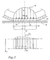
- Fig. 2 schematically illustrates one preferred tire model to be used in the method of the present invention, namely the so called brush model.
- the brush model is obtained by dividing the volume of a tire 20 in the contact region - or contact patch 22 - into small brush elements, or bristles, see Fig. 2 .
- Each bristle is assumed to deform independently in the longitudinal and lateral directions.
- Useful in the model is the separation of the contact patch 22 into one adhesive 24 and one sliding 26 region. In the adhesive region 24, the bristles adhere to a road surface 28 and the deformation force is carried by static friction. In the sliding region 26, the bristles slide across the road surface 28 under influence of sliding friction.
- ⁇ ( ⁇ i , C oi , ⁇ ) denotes the normalized tire force
- ⁇ x 0 3 ⁇ ⁇ / C 0 ⁇ x
- ⁇ y 0 3 ⁇ ⁇ / C 0 ⁇ y
- C 0 x , C 0y denotes the normalized tire stiffness and ⁇ is the friction coefficient.
- the rolling radius of a wheel is denoted R e and ⁇ is the rotational velocity of the wheel.
- the expression according to Eq. 2 is a preferred expression for the slip of the wheel which expression is useful when estimating the friction between the tire and the road. As such, the expression according to Eq. 2 is preferred when establishing methods for determining at least a first parameter - such as the friction - relating to a wheel-to-road contact.
- a first parameter determination method comprising the following steps:
- the fictive relation E may have to be adjusted to that specific load case.
- the fictive relation E may be adjusted so as to model a specific physical condition, e.g. an equilibrium in forces or moments in a specific direction.
- the parameters governing that specific condition may also have to be adjusted, resulting in that fictive relations E for different load cases may include different sets of input parameters. This will be explained more thoroughly hereinbelow for different load cases: a lateral case, a longitudinal case and a combinations thereof, starting with a lateral case.
- the caster offset of a wheel is defined as the distance on the road between where the vertical post, e.g. a strut of a wheel suspension, would touch the road and the point where the wheel touches the road. Furthermore, the parameter a in Eq. 3 stipulates half the tire effective length in the longitudinal direction x of the contact patch.
- the equation governing the aligning torque M z is dependent on the actual contact condition between the wheel and the road, wherein the condition denoted NS is indicative of that the contact is non-saturated and the condition denoted S is indicative of that the contact is saturated, i.e. that there is no adhesion in the contact patch.
- the relation as defined in Eq. 4 may constitute the fictive relation E as laid out in the description of the general parameter determination method of the present invention.
- the wheel parameters included in the fictive relation E - and which parameters thus need to be determined in the determination method of the present invention - are: the aligning moment M z , the lateral force F y , the vertical force F z and the caster offset of the wheel ⁇ c .
- the relation defined therein comprises two unknown parameters, the first one being the tire-to-road friction ⁇ and the other being the half the tire effective length a.
- the tire-to-road friction ⁇ may be regarded as the first parameter whereas half the tire effective length a may be regarded as the second parameter.
- the method of determining the first parameter - which in this case is the tire-to-road friction ⁇ - may for the lateral case be regarded as comprising a step of finding the parameter pair ( ⁇ ,a) fulfilling the fictive relation E as presented in Eq. 4.
- the set of second parameters in this case includes only one parameter, namely half the tire effective length a.
- the parameter a relating to half the tire effective length will be referred to as a second parameter.
- the present invention proposes a step of establishing a quality measure QM, which quality measure QM is indicative of how well the fictive relation E is fulfilled.
- the problem of finding the parameter pair ( ⁇ ,a) fulfilling the fictive relation E may now be reformulated as how to find an appropriate parameter pair ( ⁇ ,a) which results in a preferred value of the quality measure QM.
- QM M z + ⁇ sign F y ⁇ F z ⁇ a ⁇ 1 - 1 - F y F z ⁇ ⁇ 1 3 ⁇ 1 - F y F z ⁇ ⁇ + ⁇ c a ⁇ F y F z ⁇ ⁇ 2
- QM M z + ⁇ sign F y ⁇ F z ⁇ a ⁇ 1 - 1 - F y F z ⁇ ⁇ 1 3 ⁇ 1 - F y F z ⁇ ⁇ + ⁇ c a ⁇ F y F z ⁇ ⁇ .
- the problem of finding a parameter pair ( ⁇ ,a) resulting in a preferred value of the quality measure QM may be regarded as an optimization problem or, even more specifically, a minimization problem, viz min ⁇ , a QM .
- the fictive relation E as well as the quality measure QM may be regarded as relating to an instantaneous wheel load condition.
- the fictive relation E as well as the quality measure QM may be regarded as relating to an instantaneous wheel load condition.
- two or more measurement samples are generally desired in order to obtain a filtered (e.g. average) value of the parameter pair ( ⁇ ,a) during a certain time period. This reasoning as regards two or more measurement samples applies to all the embodiments of the present invention presented hereinbelow.
- the minimization problem as presented in Eq. 9 may be solved in a plurality of ways in order to obtain the preferred parameter pair ( ⁇ ,a).
- the determination method of the present invention proposes two preferred implementations of a method of solving the above minimization problem, which implementations are presented hereinbelow.
- each one of the two implementations is based on an insight made by the inventors of the present invention, namely that the fictive relation E in the lateral case, i.e. the relation E relating to the aligning moment M z as stipulated in Eq. 4, is not linearly proportional to the first parameter, i.e. the tire-to-road friction ⁇ .
- This implementation of the method of finding the appropriate values of the parameter pair ( ⁇ ,a) may be referred to as a grid-approach and is illustrated in Fig. 3 .
- the corresponding value of the quality measure QM may be determined and the combination of the first and second parameter ( ⁇ i ,a j ) resulting in the most preferred, which generally is the lowest, value of the quality measure is selected to constitute the preferred parameter pair ( ⁇ ,a).
- a further variant of the first implementation may comprise the steps of firstly selecting the sets of the first and second parameters ⁇ ,a and then determining the value of the quality measure QM for a plurality, preferably all, of the combinations of the sets of the first and second parameters wherein the order of combining the sets may be selected according to a predetermined scheme or may even be selected randomly.
- the second implementation utilizes the insight that the fictive relation E, c.f. Eq. 4, is in fact linearly proportional to the second parameter a.
- the aligning moment M z is an affine function of the second parameter a.
- a value of the second parameter a i as well as the corresponding local value of the quality measure QM i is determined. Then, the values of all the local quality measures QM i are compared to one another and the lowest local quality measure QM i is selected to be the preferred one. The corresponding values of the first and second parameters ⁇ ⁇ , a i are thus selected to constitute the preferred parameter pair ( ⁇ ,a).
- assumption a) hereinabove a person skilled in the art may realize that this assumption may be most preferred when studying two wheels 12, 18 which are located on the same side of a vehicle 10 since it is likely that these to wheels will experience approximately the same wheel-to-road contact. However, there may of course be situations, e.g. when the vehicle 10 is travelling on a substantially homogenous road, wherein assumption a) may be appropriate for any two wheels of a vehicle 10.
- a relation between the longitudinal velocity v x 1 of the first wheel 12 and the longitudinal velocity v x 2 of the second wheel 18 may be established.
- the above-mentioned relation is formulated such that the longitudinal velocity v x 1 of the first wheel 12 is assumed to equal the longitudinal velocity v x 2 of the second wheel 18, i.e. the stiffnesses of the members connecting the first and second wheels 12, 18 are assumed to be infinitely high.
- the constants K 1 and K 2 of Eq. 12 are in this case assumed to be zero.
- the left hand side LHS of the equation contains data which may be determined by direct or indirect measurements, namely data as regards the rolling radius R e and the rotational velocity ⁇ of each wheel 12, 18 and these data are also present in the right hand side RHS.
- the right hand side RHS of Eq. 15 contains data as regards the normalized longitudinal forces f x1 , f x2 of each wheel which forces may be estimated by a simple dynamic load transfer method which will be presented in detail hereinbelow.
- the relation according to Eq. 15 may be regarded as constituting the fictive relation E.
- Eq. 15 may be regarded as an alternative to Eq. 4 to constitute the fictive relation E.
- the parameters thus needed to be determined in the parameter determination method of the present invention are the rolling radius R e ; the rotational velocity ⁇ and normalized longitudinal force f x of each one of the first 12 and second 18 wheels, respectively.
- the equation presented in Eq. 16 may be referred to as a longitudinal force relation RF x .
- the distribution of the driving or braking is normalized, such that: ⁇ i ⁇ i ⁇ 1.
- the distribution ⁇ i may correspond to a normalized pressure of the braking system for each wheel of the vehicle.
- the unknown parameters of the fictive relation E namely the friction ⁇ and the tire stiffnesses C ox1 , C ox2 of the first and second wheel, respectively, may be estimated by a method similar to the one presented for the lateral case.
- a quality measure QM indicative of how well the fictive relation E according to Eq. 15 is fulfilled is firstly established. Examples of appropriate quality measures QM for Eq.
- the problem of finding a parameter set ( ⁇ ,C ox1 , C ox2 ) resulting in a preferred value of the quality measure QM may be regarded as an optimization problem or, even more specifically, a minimization problem, viz min ⁇ , C 0 ⁇ x ⁇ 1 , C 0 ⁇ x ⁇ 2 QM .
- Obtaining the values of the first and second tire stiffness C ox1 , C ox2 may be performed by utilizing traditional linear minimization techniques.
- the fictive relation E in the longitudinal case as stipulated in Eq. 15 is linearly proportional to the inverse of the tire stiffnesses C ox1 , C ox2 .
- the second implementation for determining an appropriate parameter set ( ⁇ ,C ox1 , C ox2 ) is basically the same as in the lateral case, be it that the minimization step for finding the local minimum QM i of the quality measure QM involves a two-dimensional minimization step, namely as regards the two parameters (1/C ox1 , 1/C ox2 ).
- the fictive relation E as defined therein is actually linearly proportional to the change ⁇ R e 1 in the rolling radius R e1 of the first wheel.
- the set of second parameters may in this case be constituted by the first and second tire stiffness C ox1 , C ox2 as well as the change ⁇ R e 1 in the rolling radius R e1 of the first wheel.
- the fictive relation E as stipulated by Eq. 15 may be expanded so as to include wheel load conditions for a plurality of time instants [t 0 ... t n ].
- the value of the first parameter relating to the tire-to-road contact - which first parameter preferably is the friction ⁇ - may be determined by a determination method which method is used in either a lateral case or a longitudinal case.
- the inventors of the present invention have also realized that either one of the aforesaid cases may be generalized to an oblique load case, i.e. a case wherein the wheel is subjected to lateral as well as longitudinal loads.
- the inventors of the present invention have realized that the relation presented in Eq. 3 may be generalized so as to also include a term relating to the load in the longitudinal direction.
- a load scenario may emanate from a driving situation wherein the vehicle 10 - onto which the wheel is mounted - is subjected to an acceleration or a retardation at the same time as the vehicle 10 is turning.
- M z - ⁇ a ⁇ f y f ⁇ ⁇ ⁇ 1 - f ⁇ + ⁇ c a ⁇ f ⁇ .
- ⁇ 1 - f ⁇ / 3 1
- f f x 2 + f y 2 .
- the relation as stipulated in Eq. 21 also includes a parameter relating to the longitudinal load f x an estimation of which has already been presented, c.f. Eq. 16.
- the relation modelling the aligning moment is an affine function of half the tire effective length a.
- appropriate values of the friction ⁇ as well as half the tire effective length a may be determined using any one of the determination methods, i.e. the first or second implementation, discussed hereinabove in conjunction with the lateral case.
- C in Eq. 22 is a parameter relating to the stiffness in the longitudinal C 0x as well as the lateral C 0y direction of the tire.
- one preferred approximation which may be introduced when formulating the relation as laid out in Eq. 22 is that the longitudinal tire stiffness equals the lateral tire stiffness.
- the determination method as previously proposed as regards the longitudinal case, c.f. Eq 10 to Eq. 20, may be modified by replacing the Eq. 2 relation for the longitudinal slip ⁇ x with the expression as stipulated in Eq. 22. Without going into details, this will result in a fictive relation E wherein the friction ⁇ and the combined stiffnesses of a first and a second wheel C 1 , C 2 are unknown parameters. Furthermore, the aforesaid fictive relation will be linearly proportional to an inverse of each one of the first and second combined tire stiffnesses C 1 , C 2 . As such, at least the first parameter - i.e.
- the friction ⁇ - may in this case be determined by a parameter determination method similar to any one of the methods discussed hereinabove with reference to the longitudinal case.
- an implementation of the method presented hereinabove may use the assumption that the combined tire stiffness C 1 of the first wheel equals the combined stiffness C 2 of the second wheel.
- the present invention provides for a method of determining at least a first parameter ⁇ relating to a wheel-to-road contact for a plurality of load cases for one or several wheels.
- the step of determining an appropriate value of the second parameter for a selected value of the first parameter may include other optimization techniques than the ones presented hereinabove.
- such optimization techniques may comprise a Fibonacci search algorithm or a Newton-Rapson search algorithm.
- a preferred determination method may comprise a step of firstly determining the actual wheel load condition, e.g. if the wheel load is longitudinal, lateral or a combination thereof, and then selecting a specific first parameter implementation, which implementation may preferably be selected from any one of the four embodiments presented hereinabove.
Landscapes
- Engineering & Computer Science (AREA)
- Transportation (AREA)
- Mechanical Engineering (AREA)
- Physics & Mathematics (AREA)
- Automation & Control Theory (AREA)
- Mathematical Physics (AREA)
- Control Of Driving Devices And Active Controlling Of Vehicle (AREA)
Claims (18)
- Ein Verfahren zum Bestimmen mindestens eines Reibkoeffizienten (µ) zwischen Rad und Straße zur Übermittlung an einen Fahrer und / oder an ein Fahrer-Assistenz-System eines Fahrzeuges, wobei das Rad eine Ausdehnung (x) in Längsrichtung und eine Ausdehnung (y) in Querrichtung hat und in welchem das Verfahren folgende Schritte umfasst:- Bestimmen einer Mehrzahl von Radparametern, die sich auf die Belastung des Rades und / oder auf die Bewegung des Rades beziehen,- Aufstellen einer fiktiven Relation (E), umfassend: wenigstens einen aus der Mehrzahl von Radparametern, wobei sich der Reibungskoeffizient (µ) und ein Satz von zweiten Parametern (a, COX1, COX2) auf den Kontakt zwischen Rad und Straße beziehen, wobei die Relation (E) zumindest während eines Falles einer längsgerichteten Rad-Belastung oder während des Falles einer seitlich ausgerichteten Rad-Belastung linear proportional zu jedem der Parameter (a, COX1, COX2) in dem Satz der zweiten Parameter oder einer Umkehrung davon ist;- Aufstellen eines Qualitätsmaßes (QM), welches anzeigt, wie gut die fiktive Relation (E) erfüllt wird,dadurch gekennzeichnet, dass das Verfahren des weiteren folgende Schritte umfasst:- Auswählen eines Satzes von einzelnen Werten {µ}i=1,n des Reibkoeffizienten (µ);- für mindestens zwei der einzelnen Werte in dem Satz:□ Festlegen des Wertes für jeden der Parameter (ai, Ci OX1, Ci OX2) in dem Satz der zweiten Parameter, was zu einem bevorzugten Qualitätsmaß (QMi) für den einzelnen Wert (µi) des Reibkoeffizienten (µ) führt;- Auswählen eines Wertes des Reibungskoeffizienten (µ) als den einzelnen Wert (µi) aus den mindestens zwei einzelnen Werten, dessen zugeordnetes bevorzugtes Qualitätsmaß QMi anzeigt, dass die fiktive Relation (E) am besten erfüllt wird.
- Verfahren nach Anspruch 1, worin das Qualitätsmaß (QM) eine Fehlerfunktion für die fiktive Relation (E) ist, so dass ein Wert von Null des Qualitätsmaßes (QM) dafür steht, dass die fiktive Relation (E) erfüllt ist.
- Verfahren nach Anspruch 2, worin der Schritt des Bestimmens des Wertes für jeden einzelnen der Parameter (ai, Ci OX1, Ci OX2) in dem Satz der zweiten Parameter einen Schritt des Minimierens des Qualitätsmaßes (QM) umfasst.
- Verfahren nach Anspruch 3, worin der Schritt des Minimierens des Qualitätsmaßes (QM) durch Anwenden einer linearen Optimierungstechnik durchgeführt wird.
- Verfahren nach einem der Ansprüche 1 bis 3, worin der Schritt des Bestimmens des Wertes für jeden einzelnen der Parameter (ai, Ci OX1, Ci- OX2) in dem Satz der zweiten Parameter folgende Schritte umfasst:- Auswählen eines zweiten Satzes von einzelnen Werten für jeden der Parameter (ai, Ci OX1, Ci OX2) in dem Satz der zweiten Parameter ({αi j}j=1, {Ci OX1j } j=1, n; {Ci OX2j } j=1, n);- für mindestens zwei der einzelnen Werte in dem zweiten Satz:□ Auswählen des Wertes von jedem einzelnen der Parameter in dem Satz der zweiten Parameter (ai, Ci OX1, Ci OX2) als den einzelnen Wert ({ai j } j=1,n; {Ci OX1i,j } j=1,n; {Ci OX2,j } j=1,n), der das bevorzugte Qualitätsmaß (QM) ergibt.
- Verfahren nach einem der vorhergehenden Ansprüche, worin das Verfahren für einen Fall einer Radlast durchgeführt wird, der eine seitliche Last (Fy) umfasst, wobei die Parameter für das Rad einen Unter-Satz umfassen, der wiederum umfasst: ein Ausricht-Drehmoment (Mz), eine vertikale Kraft (Fz) und die seitliche Kraft (Fy) des Rades, wobei die fiktive Relation (E) den Unter-Satz beinhaltet.
- Verfahren nach Anspruch 6, worin die fiktive Relation (E) weiterhin folgende Parameter beinhaltet: die Reibung (µ) zwischen Rad und Straße, einen Längenparameter (a), der sich auf eine wirksame Länge einer Kontaktfläche zwischen dem Rad und der Straße bezieht, und einen Nachlaufversatz (δc) des Rades, wobei der Längenparameter (a) in dem Satz von zweiten Parametern enthalten ist.
- Verfahren nach Anspruch 6 oder 7, worin das Rad an einem Fahrzeug (10) befestigt ist und die seitliche Kraft (Fy) durch eine Relation (RFy) bestimmt wird, die folgende Parameter umfasst: Eine Masse (m) des Fahrzeugs, eine Beschleunigung (ax) des Fahrzeuges in Längsrichtung, eine Querbeschleunigung (ay) des Fahrzeugs und eine Gierbeschleunigung (ψ") des Fahrzeugs.
- Verfahren nach einem der Ansprüche 6 bis 8, worin der Lastfall auch eine Last (Fx) in Längsrichtung umfasst und die fiktive Relation (E) auch einen Radparameter einschließt, der die Last (Fx) in Längsrichtung verkörpert.
- Verfahren nach einem der Ansprüche 1 bis 5, worin das Verfahren für ein Fahrzeug (10) durchgeführt wird, das ein erstes und ein zweites Rad (12, 18) während eines Lastfalles umfasst, der eine Kraft (Fx) in Längsrichtung beinhaltet, wobei das erste Rad (12) eine erste Geschwindigkeit (vx1) in Längsrichtung und das zweite Rad (18) eine zweite Geschwindigkeit (vx2) in Längsrichtung aufweist, wobei das Verfahren einen Schritt umfasst, eine Beziehung zwischen den ersten und zweiten Geschwindigkeiten (vx1, vx2) in Längsrichtung aufzustellen und wobei die fiktive Relation (E) folgende Parameter einschließt: eine Last (Fx1) in Längsrichtung des ersten Rades (12) und eine Last (Fx2) in Längsrichtung des zweiten Rades (18).
- Verfahren nach Anspruch 10, worin die fiktive Relation (E) weiter folgende Parameter einschließt: eine erste Steifigkeit (Cx1) in Längsrichtung des Reifens des ersten Rades (12), eine zweite Steifigkeit (Cx2) in Längsrichtung des Reifens des zweiten Rades (18) und den Reibkoeffizienten (µ) zwischen Rad und Straße, wobei angenommen wird, dass der Reibkoeffizient (µ) zwischen Rad und Straße für die ersten und zweiten Räder (12,18) gleich ist und wobei die ersten und zweiten Steifigkeiten (Cx1, Cx2) in Längsrichtung der Reifen in dem Satz von zweiten Parametern enthalten sind.
- Verfahren nach Anspruch 10, worin der Lastfall auch eine Last (Fy) in seitlicher Richtung umfasst und die fiktive Relation (E) weiter umfasst: einen Radparameter, der die Last (Fy) in seitlicher Richtung verkörpert, eine erste kombinierte Steifigkeit (C1) des Reifens des ersten Rades (12) und eine zweite kombinierte Steifigkeit (C2) des Reifens des zweiten Rades (18), wobei die ersten und zweiten kombinierten Steifigkeiten (C1, C2) der Reifen in dem Satz von zweiten Parametern enthalten sind.
- Verfahren nach Anspruch 11 oder 12, worin die fiktive Relation (E) weiter folgende Parameter umfasst, einen wirksamen Abrollradius (Re1) des ersten Rades (12), einen wirksamen Abrollradius (Re2) des zweiten Rades (18), eine Winkelgeschwindigkeit (ω1) des ersten Rades und eine Winkels geschwindigkeit (ω2) des zweiten Rades.
- Verfahren nach einem der Ansprüche 9 bis 13, worin das Rad an einem Fahrzeug montiert ist und die Kraft (Fx) in Längsrichtung durch eine Längskraft-Relation (RFx) bestimmt wird, die folgende Parameter beinhaltet: eine Fahrzeugmasse (m), eine Fahrzeugbeschleunigung (ax) in Längsrichtung und einen Parameter (γ), der eine Antriebs- oder Bremskraft zwischen den Rädern (12,18) des Fahrzeugs (10) verkörpert.
- Verfahren nach einem der vorhergehenden Ansprüche, worin die fiktive Relation (E) wiederum eine Mehrzahl von fiktiven Unter-Relationen (Ei) umfasst, wobei jede einzelne der Unter-Relationen (Ei) wenigstens einen aus der Mehrzahl von Rad-Parametern, den Reibkoeffizienten (µ) und einen Satz von zweiten Parametern (a, Cox1, Cox2), die sich auf den Kontakt zwischen Rad und Straße beziehen, beinhaltet, wobei jede der Unter-Relationen (Ei) einen Lastfall zu einem bestimmten Zeitpunkt (ti) verkörpert.
- Computerprogrammprodukt, dadurch gekennzeichnet, dass es ein Computerprogramm umfasst, das einen Computer-Programmcode beinhaltet, der auf einem Computer oder Prozessor ausführbar ist, um alle Schritte eines Verfahrens nach einem der Ansprüche 1 bis 15 zu verwirklichen, wobei das Produkt in einem durch Computer lesbaren Medium oder einer Trägerwelle gespeichert ist.
- Elektronische Steuereinheit (ECU), dadurch gekennzeichnet, dass sie ein Computerprogrammprodukt nach Anspruch 16 umfasst, das so ausgelegt ist, ein Verfahren zum Bestimmen eines Reibkoeffizienten gemäß einem der Ansprüche 1 bis 15 auszuführen.
- Fahrzeug, dadurch gekennzeichnet, dass es eine Elektronische Steuereinheit (ECU) nach Anspruch 17 umfasst.
Priority Applications (1)
| Application Number | Priority Date | Filing Date | Title |
|---|---|---|---|
| EP20080159122 EP2138372B1 (de) | 2008-06-26 | 2008-06-26 | Schätzung des Fahrzeug-Straße-Kontaktes |
Applications Claiming Priority (1)
| Application Number | Priority Date | Filing Date | Title |
|---|---|---|---|
| EP20080159122 EP2138372B1 (de) | 2008-06-26 | 2008-06-26 | Schätzung des Fahrzeug-Straße-Kontaktes |
Publications (2)
| Publication Number | Publication Date |
|---|---|
| EP2138372A1 EP2138372A1 (de) | 2009-12-30 |
| EP2138372B1 true EP2138372B1 (de) | 2012-08-08 |
Family
ID=40122012
Family Applications (1)
| Application Number | Title | Priority Date | Filing Date |
|---|---|---|---|
| EP20080159122 Ceased EP2138372B1 (de) | 2008-06-26 | 2008-06-26 | Schätzung des Fahrzeug-Straße-Kontaktes |
Country Status (1)
| Country | Link |
|---|---|
| EP (1) | EP2138372B1 (de) |
Cited By (2)
| Publication number | Priority date | Publication date | Assignee | Title |
|---|---|---|---|---|
| CN105829185A (zh) * | 2013-12-18 | 2016-08-03 | 米其林集团总公司 | 通过评估滚动半径来估计潜在附着力 |
| US10011284B2 (en) | 2016-07-13 | 2018-07-03 | Mitsubishi Electric Research Laboratories, Inc. | System and method for determining state of stiffness of tires of vehicle |
Families Citing this family (7)
| Publication number | Priority date | Publication date | Assignee | Title |
|---|---|---|---|---|
| US8998765B2 (en) | 2010-07-14 | 2015-04-07 | E-Aam Driveline Systems Ab | Axle assembly with torque distribution drive mechanism |
| US8663051B2 (en) | 2010-07-14 | 2014-03-04 | E-Aam Driveline Systems Ab | Axle assembly with torque distribution drive mechanism |
| ITRM20110550A1 (it) * | 2011-10-19 | 2013-04-20 | Bridgestone Corp | Metodo di stima per determinare la forza laterale di un pneumatico di un veicolo che percorre una curva con fondo a bassa aderenza |
| US9751533B2 (en) * | 2014-04-03 | 2017-09-05 | The Goodyear Tire & Rubber Company | Road surface friction and surface type estimation system and method |
| US9840118B2 (en) | 2015-12-09 | 2017-12-12 | The Goodyear Tire & Rubber Company | Tire sensor-based robust road surface roughness classification system and method |
| JP6975624B2 (ja) * | 2017-11-29 | 2021-12-01 | Toyo Tire株式会社 | 制動性能評価方法 |
| US11298991B2 (en) | 2018-11-28 | 2022-04-12 | The Goodyear Tire & Rubber Company | Tire load estimation system and method |
Family Cites Families (6)
| Publication number | Priority date | Publication date | Assignee | Title |
|---|---|---|---|---|
| DE59304134D1 (de) | 1993-06-22 | 1996-11-14 | Siemens Ag | Verfahren und Schaltungsanordnung zum Ermitteln des Reibwerts |
| JP3633120B2 (ja) * | 1996-07-18 | 2005-03-30 | 日産自動車株式会社 | 車体速および路面摩擦係数推定装置 |
| JP2001171504A (ja) * | 1999-12-16 | 2001-06-26 | Nissan Motor Co Ltd | 路面摩擦係数推定装置 |
| US6549842B1 (en) * | 2001-10-31 | 2003-04-15 | Delphi Technologies, Inc. | Method and apparatus for determining an individual wheel surface coefficient of adhesion |
| JP3853344B2 (ja) * | 2005-02-23 | 2006-12-06 | 横浜ゴム株式会社 | タイヤの摩耗予測方法、タイヤの設計方法、タイヤの製造方法、タイヤの摩耗予測システム及びプログラム |
| DE102005060219A1 (de) * | 2005-12-16 | 2007-06-21 | Ford Global Technologies, LLC, Dearborn | Verfahren und Vorrichtung zur Abschätzung des Reibkoeffizienten zwischen Straße und Reifen eines Kraftfahrzeuges |
-
2008
- 2008-06-26 EP EP20080159122 patent/EP2138372B1/de not_active Ceased
Cited By (3)
| Publication number | Priority date | Publication date | Assignee | Title |
|---|---|---|---|---|
| CN105829185A (zh) * | 2013-12-18 | 2016-08-03 | 米其林集团总公司 | 通过评估滚动半径来估计潜在附着力 |
| CN105829185B (zh) * | 2013-12-18 | 2019-03-19 | 米其林集团总公司 | 通过评估滚动半径来估计潜在附着力 |
| US10011284B2 (en) | 2016-07-13 | 2018-07-03 | Mitsubishi Electric Research Laboratories, Inc. | System and method for determining state of stiffness of tires of vehicle |
Also Published As
| Publication number | Publication date |
|---|---|
| EP2138372A1 (de) | 2009-12-30 |
Similar Documents
| Publication | Publication Date | Title |
|---|---|---|
| EP2138372B1 (de) | Schätzung des Fahrzeug-Straße-Kontaktes | |
| Singh et al. | Estimation of tire–road friction coefficient and its application in chassis control systems | |
| EP3028909B1 (de) | Intelligentes reifenbasiertes fahrbahnreibungsschätzsystem und -verfahren | |
| EP3106360B1 (de) | Verfahren und anordnung zur reibwertschätzung zwischen reifen und fahrbahn | |
| EP3309024B1 (de) | Verfahren und system zur bestimmung der reibung zwischen dem boden und einem reifen eines fahrzeuges | |
| Doumiati et al. | Observers for vehicle tyre/road forces estimation: experimental validation | |
| CN103476657B (zh) | 用于路面摩擦系数的实时估计的方法和装置 | |
| Beal | Rapid road friction estimation using independent left/right steering torque measurements | |
| EP3822137B1 (de) | Fahrzeugsteuerungsverfahren und -vorrichtung | |
| JP3633120B2 (ja) | 車体速および路面摩擦係数推定装置 | |
| US20090177346A1 (en) | Dynamic estimation of vehicle inertial parameters and tire forces from tire sensors | |
| JP7252336B2 (ja) | タイヤの剛性の推定及び道路摩擦の推定の方法、使用、コンピュータプログラム製品、及び装置 | |
| US20030163237A1 (en) | Method of controlling traveling stability of vehicle | |
| Li et al. | Comparative study of vehicle tyre–road friction coefficient estimation with a novel cost-effective method | |
| JPH09249010A (ja) | 初期補正係数演算装置およびこれを利用した装置 | |
| CN117360522A (zh) | 路面峰值附着系数确定方法、装置、电子设备及存储介质 | |
| KR20220022514A (ko) | 노면 마찰계수 추정 장치 및 방법 | |
| JP5206490B2 (ja) | 車両接地面摩擦状態推定装置及びその方法 | |
| US8473174B2 (en) | Method for determining the vehicle longitudinal velocity in a vehicle | |
| Do et al. | Real-time estimation of longitudinal tire stiffness considering dynamic characteristics of tire | |
| Kunjunni et al. | Effect of load distribution on longitudinal and lateral forces acting on each wheel of a compact electric vehicle | |
| JP6037301B2 (ja) | タイヤ消散エネルギー推定装置、方法、及びプログラム | |
| WO2020193860A1 (en) | Modelling dynamics of a vehicle | |
| JP2002104158A (ja) | 路面摩擦状態演算装置、タイヤ種別判定装置、タイヤ摩耗判定装置、路面傾斜推定装置及び加速度センサのオフセット補正装置 | |
| CN116127600A (zh) | 三轴牵引车滑移率的误差消除方法、装置及电子设备 |
Legal Events
| Date | Code | Title | Description |
|---|---|---|---|
| PUAI | Public reference made under article 153(3) epc to a published international application that has entered the european phase |
Free format text: ORIGINAL CODE: 0009012 |
|
| AK | Designated contracting states |
Kind code of ref document: A1 Designated state(s): AT BE BG CH CY CZ DE DK EE ES FI FR GB GR HR HU IE IS IT LI LT LU LV MC MT NL NO PL PT RO SE SI SK TR |
|
| AX | Request for extension of the european patent |
Extension state: AL BA MK RS |
|
| 17P | Request for examination filed |
Effective date: 20100611 |
|
| AKX | Designation fees paid |
Designated state(s): DE GB SE |
|
| RAP1 | Party data changed (applicant data changed or rights of an application transferred) |
Owner name: VOLVO CAR CORPORATION Owner name: HALDEX BRAKE PRODUCTS AKTIEBOLAG |
|
| GRAJ | Information related to disapproval of communication of intention to grant by the applicant or resumption of examination proceedings by the epo deleted |
Free format text: ORIGINAL CODE: EPIDOSDIGR1 |
|
| GRAP | Despatch of communication of intention to grant a patent |
Free format text: ORIGINAL CODE: EPIDOSNIGR1 |
|
| GRAP | Despatch of communication of intention to grant a patent |
Free format text: ORIGINAL CODE: EPIDOSNIGR1 |
|
| RAP1 | Party data changed (applicant data changed or rights of an application transferred) |
Owner name: VOLVO CAR CORPORATION Owner name: HALDEX BRAKE PRODUCTS AKTIEBOLAG |
|
| GRAS | Grant fee paid |
Free format text: ORIGINAL CODE: EPIDOSNIGR3 |
|
| GRAA | (expected) grant |
Free format text: ORIGINAL CODE: 0009210 |
|
| AK | Designated contracting states |
Kind code of ref document: B1 Designated state(s): DE GB SE |
|
| REG | Reference to a national code |
Ref country code: GB Ref legal event code: FG4D |
|
| REG | Reference to a national code |
Ref country code: DE Ref legal event code: R096 Ref document number: 602008017755 Country of ref document: DE Effective date: 20121004 |
|
| PG25 | Lapsed in a contracting state [announced via postgrant information from national office to epo] |
Ref country code: SE Free format text: LAPSE BECAUSE OF FAILURE TO SUBMIT A TRANSLATION OF THE DESCRIPTION OR TO PAY THE FEE WITHIN THE PRESCRIBED TIME-LIMIT Effective date: 20120808 |
|
| PLBE | No opposition filed within time limit |
Free format text: ORIGINAL CODE: 0009261 |
|
| STAA | Information on the status of an ep patent application or granted ep patent |
Free format text: STATUS: NO OPPOSITION FILED WITHIN TIME LIMIT |
|
| 26N | No opposition filed |
Effective date: 20130510 |
|
| REG | Reference to a national code |
Ref country code: DE Ref legal event code: R097 Ref document number: 602008017755 Country of ref document: DE Effective date: 20130510 |
|
| GBPC | Gb: european patent ceased through non-payment of renewal fee |
Effective date: 20130626 |
|
| PG25 | Lapsed in a contracting state [announced via postgrant information from national office to epo] |
Ref country code: GB Free format text: LAPSE BECAUSE OF NON-PAYMENT OF DUE FEES Effective date: 20130626 |
|
| PGFP | Annual fee paid to national office [announced via postgrant information from national office to epo] |
Ref country code: DE Payment date: 20220613 Year of fee payment: 15 |
|
| REG | Reference to a national code |
Ref country code: DE Ref legal event code: R119 Ref document number: 602008017755 Country of ref document: DE |
|
| PG25 | Lapsed in a contracting state [announced via postgrant information from national office to epo] |
Ref country code: DE Free format text: LAPSE BECAUSE OF NON-PAYMENT OF DUE FEES Effective date: 20240103 |