EP2138249A1 - Werkzeug zur Herstellung von clinchartigen Verbindungen - Google Patents
Werkzeug zur Herstellung von clinchartigen Verbindungen Download PDFInfo
- Publication number
- EP2138249A1 EP2138249A1 EP08159293A EP08159293A EP2138249A1 EP 2138249 A1 EP2138249 A1 EP 2138249A1 EP 08159293 A EP08159293 A EP 08159293A EP 08159293 A EP08159293 A EP 08159293A EP 2138249 A1 EP2138249 A1 EP 2138249A1
- Authority
- EP
- European Patent Office
- Prior art keywords
- die
- elements
- tool
- tool part
- figures
- Prior art date
- Legal status (The legal status is an assumption and is not a legal conclusion. Google has not performed a legal analysis and makes no representation as to the accuracy of the status listed.)
- Granted
Links
- 238000000034 method Methods 0.000 description 10
- 239000000463 material Substances 0.000 description 9
- 230000015572 biosynthetic process Effects 0.000 description 4
- 230000000903 blocking effect Effects 0.000 description 4
- 239000002184 metal Substances 0.000 description 4
- 235000001674 Agaricus brunnescens Nutrition 0.000 description 2
- 230000000717 retained effect Effects 0.000 description 2
- 229910000639 Spring steel Inorganic materials 0.000 description 1
- 230000001154 acute effect Effects 0.000 description 1
- 238000006073 displacement reaction Methods 0.000 description 1
- 230000000694 effects Effects 0.000 description 1
- 229920001971 elastomer Polymers 0.000 description 1
- 239000000806 elastomer Substances 0.000 description 1
- 239000013536 elastomeric material Substances 0.000 description 1
- 230000003993 interaction Effects 0.000 description 1
- 229910052755 nonmetal Inorganic materials 0.000 description 1
- 239000012858 resilient material Substances 0.000 description 1
- 230000003019 stabilising effect Effects 0.000 description 1
Images


Classifications
-
- B—PERFORMING OPERATIONS; TRANSPORTING
- B21—MECHANICAL METAL-WORKING WITHOUT ESSENTIALLY REMOVING MATERIAL; PUNCHING METAL
- B21D—WORKING OR PROCESSING OF SHEET METAL OR METAL TUBES, RODS OR PROFILES WITHOUT ESSENTIALLY REMOVING MATERIAL; PUNCHING METAL
- B21D39/00—Application of procedures in order to connect objects or parts, e.g. coating with sheet metal otherwise than by plating; Tube expanders
- B21D39/03—Application of procedures in order to connect objects or parts, e.g. coating with sheet metal otherwise than by plating; Tube expanders of sheet metal otherwise than by folding
- B21D39/031—Joining superposed plates by locally deforming without slitting or piercing
-
- B—PERFORMING OPERATIONS; TRANSPORTING
- B23—MACHINE TOOLS; METAL-WORKING NOT OTHERWISE PROVIDED FOR
- B23P—METAL-WORKING NOT OTHERWISE PROVIDED FOR; COMBINED OPERATIONS; UNIVERSAL MACHINE TOOLS
- B23P19/00—Machines for simply fitting together or separating metal parts or objects, or metal and non-metal parts, whether or not involving some deformation; Tools or devices therefor so far as not provided for in other classes
- B23P19/04—Machines for simply fitting together or separating metal parts or objects, or metal and non-metal parts, whether or not involving some deformation; Tools or devices therefor so far as not provided for in other classes for assembling or disassembling parts
- B23P19/06—Screw or nut setting or loosening machines
- B23P19/062—Pierce nut setting machines
-
- B—PERFORMING OPERATIONS; TRANSPORTING
- B21—MECHANICAL METAL-WORKING WITHOUT ESSENTIALLY REMOVING MATERIAL; PUNCHING METAL
- B21D—WORKING OR PROCESSING OF SHEET METAL OR METAL TUBES, RODS OR PROFILES WITHOUT ESSENTIALLY REMOVING MATERIAL; PUNCHING METAL
- B21D39/00—Application of procedures in order to connect objects or parts, e.g. coating with sheet metal otherwise than by plating; Tube expanders
- B21D39/03—Application of procedures in order to connect objects or parts, e.g. coating with sheet metal otherwise than by plating; Tube expanders of sheet metal otherwise than by folding
- B21D39/031—Joining superposed plates by locally deforming without slitting or piercing
- B21D39/032—Joining superposed plates by locally deforming without slitting or piercing by fitting a projecting part integral with one plate in a hole of the other plate
-
- Y—GENERAL TAGGING OF NEW TECHNOLOGICAL DEVELOPMENTS; GENERAL TAGGING OF CROSS-SECTIONAL TECHNOLOGIES SPANNING OVER SEVERAL SECTIONS OF THE IPC; TECHNICAL SUBJECTS COVERED BY FORMER USPC CROSS-REFERENCE ART COLLECTIONS [XRACs] AND DIGESTS
- Y10—TECHNICAL SUBJECTS COVERED BY FORMER USPC
- Y10T—TECHNICAL SUBJECTS COVERED BY FORMER US CLASSIFICATION
- Y10T29/00—Metal working
- Y10T29/53—Means to assemble or disassemble
- Y10T29/53996—Means to assemble or disassemble by deforming
Definitions
- the present invention relates to a tool for making joints of the so called clinch type between two or several sheet formed members of metal or non-metal.
- a suitable tool comprises generally two separate tool parts which co-operate for producing said joint.
- a first tool part has the form of a punch which in a linear movement is driven in the direction of a co-axial second tool part in the form of a die with a die cavity at the bottom of which an anvil is arranged.
- the sheet formed members are positioned against the second tool part, the die, provided with movable die elements arranged sliding laterally on a support surface against the forces from a spring element.
- the spring element is generally constituted by a ring made of an elastomer or a toroid formed metal spring surrounding the movable die elements.
- the approaching punch impacts on the surface of one of the members to be joined.
- the material of the two members is first drawn into the die cavity and subsequently due to the interaction between the punch and the anvil at the bottom of the cavity laterally extruded thereby displacing the movable die elements outwardly creating in the sheet formed members a mushroom formed button which interlocks the members.
- the invention is related to a complete tool with a punch-die combination, a separate die and a special form of the spring element used in this type of tool.
- the main part of the description will be attributed to the special characteristics of the die and the spring element.
- the punch could be of the conventional type on which the active free end has a cylindrical form, but other forms could be envisaged as well, e.g. slightly conical forms.
- One of the objects of the present invention is to provide a very robust and wear resistant tool.
- a tool according to the invention is possible to realise with very small dimensions especially in the embodiment with only two movable die elements which makes it suitable for use in narrow environments.
- a further object of the invention is to provide a die element on which the movable die elements are very precisely and efficiently guided in their reciprocating movent at the same time as they are efficiently locked against vertical movement. Vertical forces are applied on the die elements at the end of the procedure when the punch and the joint are retracted from the die cavity.
- a still further object of the invention is to provide a new type of spring element which has decisive advantages over spring elements known in the prior art.
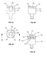
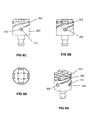
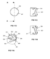
- Figures 1A-D show in different views a first embodiment of the second tool part according to the invention without the movable die elements 108, cf. for instance figure 2A .
- Figure 1A shows the tool part in a perspective view.
- the tool part body 101 carries on its upper surface in this embodiment four support elements 103 arranged on one hand to support, by means of their upper surfaces 110, the sheet formed members (not shown) to be joined together during the joining process, and on the other hand to support and guide the movable die elements 108 in their lateral movement.
- the four support elements 103 are in this embodiment arranged symmetrically around, and at a certain distance from, an anvil 102 having an upper generally flat surface 106.
- the space between the support elements 103 has been given a form such that it in co-operation with the form of the movable die elements 108 will block the vertical movement of the elements 108, i.e. in the direction parallel to the axis of the tool part 101.
- the side walls 104 of the support elements 103 are generally flat and parallel to the same axis and are stabilising and guiding the movable elements in their lateral movement.
- the vertical blocking can be achieved by giving the elements 108 a somewhat larger section at their lower part which co-operates with a corresponding grove 107 at the lower part of the space between the support elements 103.
- the horizontal generally flat surface 105 supports the sliding movement of the elements 108.
- Figure 1B shows a side view of the same embodiment.
- the form of the grove 107 is here clearly visible.
- the arrangement for the vertical blocking could be realised in other ways, e.g. by means of a classical dovetailed grove.
- the grove could alternatively be arranged in the movable element 108 co-operating with a rim arranged on the sidewall 104, etc..
- Figure 1C shows a section through the tool part 101 along the line A-A of figure 1D .
- the anvil 102 is here represented as a separate part inserted in a dead-end hole at the centre of the tool part 101. This arrangement makes it easy to change the anvil and adjust the depth of the die cavity depending on e.g. the thickness of the sheet formed members to be joined.
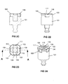
- Figures 2A-D show in different views the first embodiment of the second tool part according to the invention including the movable die elements 108 in the initial closed position. This is the position at the start of a joining procedure.
- the die elements 108 are kept in position by means of some spring element, an example of which will be described more in detail below. It should be noted, however, that traditional spring elements like elastomeric spring sleeves and toroid formed metal springs could be used.
- the die cavity has a generally cylindrical form defined by the upper generally flat surface 106 on the anvil and the side walls 109 of the four die elements 108.
- the sidewalls 109 are here illustrated as vertical but could in other embodiments have a somewhat conical form creating a die cavity with different diameters at the top and the bottom.
- the sheet formed members (not shown) to be joined together are supported by the upper surfaces 110 on the support elements 103 during the joining process.
- the vertical forces on the tool part will, during the formation of the joint, be considerable.
- the vertical dimension of the elements 108 could advantageously be chosen so that the upper generally flat surface 111 of the elements 108 will be somewhat lower than the upper surface 110 on the support elements 103.
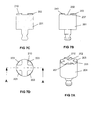
- Figures 3A-D show in different views the first embodiment of the second tool part according to the invention including the movable die elements 108 in the open position.
- the elements 108 are retained in place by means of the spring means e.g. of the type shown in the figures 4 and 6 .
- the joining procedure not necessarily open the die cavity as much as shown in figure 3 and could be finalized before the deformed material in the joint touches the support elements 103.
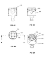
- Figures 4A-D show in different views the first embodiment of the second tool part according to the invention including the movable die elements 108 in the closed position and additionally provided with a spring element 301 according to the invention.
- the element 301 has the general form of a cylindrical cage the surface of which has been provided with four slots having an acute angle, not necessarily constant, relative the axis of the cage to form four long elastic arms or blades 303 equally partitioned around the circumference with their free ends at the upper edge of the cage.
- the free end of each blade 303 is in this embodiment provided with a bent flange 304 arranged to bear against the movable element 108 to transfer the spring force to said element. It is understood that the bent flange 304 or another means for transferring the spring force is not always necessary.
- the inner diameter of the cage corresponds to the outer diameter of the tool part body 101 and the positioning of the cage is made by sliding the cage over the tool part body.
- the cage is made of some suitable resilient material such as spring steel and the material the form and length of the blades are chosen to give the appropriate spring force for the movable elements 108.
- the spring element according to the invention is very compact, easy to change and has excellent properties.
- Figures 5A-D show in different views the embodiment according to figures 1A-D additionally provided with channels 112 for compressed air in the body of the tool part 101.
- Figures 5C and 5D show advantageous positions of the outlets 113 from the channels.
- Figures 6A-D show in different views the first embodiment of the second tool part according to the invention including the movable die elements 108 in the closed position and additionally provided with a spring element 303 according to the invention and air channels 112 in the body of the tool part 101.
- the lower end portion 302 of the slots has been given a form to leave the openings of the air channels 112 free.
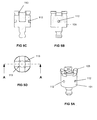
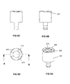
- Figures 7A-D show in different views a second embodiment of the second tool part according to the invention without the movable die elements.
- Figure 7A shows the tool part in a perspective view.
- the tool part body 201 carries on its upper surface in this embodiment four support elements 203 arranged on one hand to support, by means of their upper surfaces 210, the sheet formed members (not shown) to be joined together during the joining process, and on the other hand to support and guide the movable die elements 208 in their lateral movement.
- the four support elements 203 are in this embodiment arranged symmetrically along the circumference of the tool part body 201 and are protruding from a generally flat surface which at the same time in its central part constitutes the anvil 202 and the surface 205 on which the movable elements are displaced.
- the space between the support elements 203 has in this embodiment too been given a form such that it in co-operation with the form of the movable die elements 208, cf. figure 8 , will block the vertical movement of the elements 208, i.e. in the direction parallel to the axis of the tool part 201.
- the vertical blocking is achieved by giving the elements 208 a somewhat larger section at their lower part which co-operates with a corresponding grove 207 at the lower part of the space between the support elements 203.
- the horizontal generally flat surface 205 supports the sliding movement of the elements 208.
- Figure 7B shows a side view of the same embodiment.
- Alternative arrangements for the vertical blocking could be realised in the same ways as for the first embodiment.
- Figures 8A-D show in different views the second embodiment of the second tool part according to the invention including the movable die elements 208 in the initial closed position. This is the position at the start of a joining procedure.
- the die elements 208 are kept in position by means of some spring element, an example of which has been described above. It should be noted, however, that traditional spring elements like spring sleeves of for instance elastomeric material and toroid formed metal springs could be used.
- the die cavity has a generally cylindrical form defined by the generally flat surface 202 on the anvil and the side walls 209 of the four die elements 208.
- the sidewalls 209 are here illustrated as vertical but could in other embodiments have a somewhat conical form creating a die cavity with different diameters at the top and the bottom.
- the sheet formed members (not shown) to be joined together are supported by the upper surfaces 210 on the support elements 203 during the joining process.
- the vertical forces on the tool part will, during the formation of the joint, be considerable.
- the vertical dimension of the elements 208 could advantageously be chosen so that the upper generally flat surface 211 of the elements 208 will be somewhat lower than the upper surface 210 on the support elements 203.
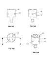
- the displacement of the movable die elements 208 in the direction of the center of the tool part 201 could be limited by means of an end stop.
- Such an end stop could e.g. be implemented by an expanded rear portion of the element 208 in co-operation with a corresponding arrangement of the width of the guiding channel between the support elements 203.
- An example of this type of end stop is illustrated in figures 13A-F , cf. below.
- the protruding anvil 102 also forms the end stop for the movable die elements 108 in the direction of the center of the tool part 101.
- One way of achieving both types of end stops could be to arrange a pin or a screw (not shown) vertically through the movable die element reaching into a co-operating elongated groove (not shown) arranged in the sliding surface 105, 205.
- the outward movement of the die elements 108, 208 will be stopped before the expanded material contacts the support elements 103, 203.
- Figures 9A-D show in different views the second embodiment of the second tool part according to the invention including the movable die elements 208 in the open position.
- the elements 208 are retained in place by means of the spring means e.g. of the type shown in the figures 4 and 6 .
- the joining procedure not necessarily open the die cavity as much as shown in figure 9 and could be finalized before the deformed material in the joint touches the support elements 203.
- Figures 10A-D show in different views the embodiment according to figures 7A-D additionally provided with channels 212 for compressed air in the body of the tool part 201.
- Figures 10C and 10D show advantageous positions of the outlets 213 from the channels.
- Figure 11A-D show in different views said spring element separately. This element has been described in detail in relation to figures 4A-D .
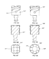
- Figure 12A-F show an embodiment according to which the movable die elements 208' have been provided with an end stop in the form of a vertical heel formed element 215 at the rear end of the elements.
- the heel element 215 could reach along the full width of the element 208' or part of the width.
- the heel element is co-operating with a corresponding recess 214 in the tool part body 201'.
- the figures 12A-C show the die-anvil combination in its open position and the figures 12D-F in its closed position.
- the spring element 301' in this case has arms 303' without a bent flange 304. This is as described above an option.
- Figure 13A-F show an embodiment according to which the movable die elements 208" have been provided with an end stop in the form of an laterally expanded rear portion 216 of the element.
- the figures 13A-C show the die-anvil combination in its open position and the figures 13D-F in its closed position.
- the side walls of the support elements 203" have been arranged with a suitable recess co-operating with the enlarged rear portion of the movable elements.
- double sided enlargements are however preferred.
- FIG 13F is illustrated how the support surfaces 210" have been changed in relation to the surfaces 210.
- the top surface 211" of the elements 208" has in this embodiment also a different form compared to the surface 211.
Landscapes
- Engineering & Computer Science (AREA)
- Mechanical Engineering (AREA)
- Forging (AREA)
- Absorbent Articles And Supports Therefor (AREA)
- Perforating, Stamping-Out Or Severing By Means Other Than Cutting (AREA)
- Insertion Pins And Rivets (AREA)
- Mounting, Exchange, And Manufacturing Of Dies (AREA)
Priority Applications (8)
| Application Number | Priority Date | Filing Date | Title |
|---|---|---|---|
| ES08159293.3T ES2463423T3 (es) | 2008-06-27 | 2008-06-27 | Herramienta para fabricar uniones de tipo remache |
| PL12178068T PL2517804T3 (pl) | 2008-06-27 | 2008-06-27 | Element sprężynowy dla narzędzi do wykonywania złączy typu przetłoczeniowego |
| EP08159293.3A EP2138249B1 (de) | 2008-06-27 | 2008-06-27 | Werkzeug zur Herstellung von clinchartigen Verbindungen |
| PL08159293T PL2138249T3 (pl) | 2008-06-27 | 2008-06-27 | Narzędzie do wykonywania złączy typu przetłoczeniowego |
| ES12178068.8T ES2448440T3 (es) | 2008-06-27 | 2008-06-27 | Elemento de resorte para herramientas que realizan uniones de tipo remache |
| EP12178068.8A EP2517804B1 (de) | 2008-06-27 | 2008-06-27 | Federelement für Werkzeuge zur Herstellung von Nietnagelverbindungen |
| US13/001,445 US9050645B2 (en) | 2008-06-27 | 2009-06-29 | Tool for making joints of clinch type |
| PCT/EP2009/058110 WO2009156519A1 (en) | 2008-06-27 | 2009-06-29 | Tool for making joints of clinch type |
Applications Claiming Priority (1)
| Application Number | Priority Date | Filing Date | Title |
|---|---|---|---|
| EP08159293.3A EP2138249B1 (de) | 2008-06-27 | 2008-06-27 | Werkzeug zur Herstellung von clinchartigen Verbindungen |
Related Child Applications (1)
| Application Number | Title | Priority Date | Filing Date |
|---|---|---|---|
| EP12178068.8A Division-Into EP2517804B1 (de) | 2008-06-27 | 2008-06-27 | Federelement für Werkzeuge zur Herstellung von Nietnagelverbindungen |
Publications (2)
| Publication Number | Publication Date |
|---|---|
| EP2138249A1 true EP2138249A1 (de) | 2009-12-30 |
| EP2138249B1 EP2138249B1 (de) | 2014-02-12 |
Family
ID=39926412
Family Applications (2)
| Application Number | Title | Priority Date | Filing Date |
|---|---|---|---|
| EP08159293.3A Not-in-force EP2138249B1 (de) | 2008-06-27 | 2008-06-27 | Werkzeug zur Herstellung von clinchartigen Verbindungen |
| EP12178068.8A Not-in-force EP2517804B1 (de) | 2008-06-27 | 2008-06-27 | Federelement für Werkzeuge zur Herstellung von Nietnagelverbindungen |
Family Applications After (1)
| Application Number | Title | Priority Date | Filing Date |
|---|---|---|---|
| EP12178068.8A Not-in-force EP2517804B1 (de) | 2008-06-27 | 2008-06-27 | Federelement für Werkzeuge zur Herstellung von Nietnagelverbindungen |
Country Status (5)
| Country | Link |
|---|---|
| US (1) | US9050645B2 (de) |
| EP (2) | EP2138249B1 (de) |
| ES (2) | ES2448440T3 (de) |
| PL (2) | PL2517804T3 (de) |
| WO (1) | WO2009156519A1 (de) |
Cited By (3)
| Publication number | Priority date | Publication date | Assignee | Title |
|---|---|---|---|---|
| FR3016307A1 (fr) * | 2014-01-13 | 2015-07-17 | Jean Claude Chabod | Outils d'assemblage sans element rapporte de tole par emboutissage sertissage de points de toutes formes, dont les matrices sont posees glissantes sur la face d'emboutissage de l'emboutissoir |
| CN106029249A (zh) * | 2013-11-04 | 2016-10-12 | 博莱豪夫亚特索集团 | 用于形成钳紧类型连结部的工具 |
| EP3527299A1 (de) * | 2018-02-14 | 2019-08-21 | Eckold GmbH & Co. KG | Matrize für ein fügewerkzeug |
Families Citing this family (2)
| Publication number | Priority date | Publication date | Assignee | Title |
|---|---|---|---|---|
| CN204221410U (zh) * | 2014-10-15 | 2015-03-25 | 富鼎电子科技(嘉善)有限公司 | 压合机构 |
| CN109411265B (zh) * | 2018-12-12 | 2023-10-10 | 国网四川省电力公司成都供电公司 | 用于梅花触头弹簧的装卸工具 |
Citations (6)
| Publication number | Priority date | Publication date | Assignee | Title |
|---|---|---|---|---|
| WO1997002912A1 (en) * | 1995-07-11 | 1997-01-30 | Attexor Equipements S.A. | A tool for making joints between sheet-formed members |
| WO2003084694A1 (de) * | 2002-04-04 | 2003-10-16 | Tox Pressotechnik Gmbh & Co. Kg | Durchsetzfügeverfahren und werkzeug dafür |
| EP1468758A1 (de) * | 2003-04-17 | 2004-10-20 | ECKOLD GmbH & Co. KG | Matrize für einen Werkzeugsatz zum mechanischen Fügen |
| DE102004033228A1 (de) * | 2004-07-08 | 2006-02-02 | Manfred Kern | Matrize und Vorrichtung zum Durchsetzfügen |
| US20060168792A1 (en) * | 2005-02-02 | 2006-08-03 | Larry Reatherford | Apparatus and method for forming a joint between adjacent members |
| US20060196034A1 (en) | 2005-03-04 | 2006-09-07 | Sawdon Edwin G | Sheet fastening apparatus and method |
Family Cites Families (4)
| Publication number | Priority date | Publication date | Assignee | Title |
|---|---|---|---|---|
| US4910853A (en) * | 1980-09-08 | 1990-03-27 | Btm Corporation | Apparatus for joining sheet material |
| SE9904167D0 (sv) * | 1999-11-16 | 1999-11-16 | Attexor Equip | Atool for joining two or several overlaying sheet formed members |
| US7150086B2 (en) * | 2001-04-04 | 2006-12-19 | Eugen Rapp | Tool that connects pieces through a process of riveting |
| WO2004074695A2 (en) * | 2003-02-14 | 2004-09-02 | Newfrey Llc | Automated monitoring for clinching joints |
-
2008
- 2008-06-27 EP EP08159293.3A patent/EP2138249B1/de not_active Not-in-force
- 2008-06-27 ES ES12178068.8T patent/ES2448440T3/es active Active
- 2008-06-27 PL PL12178068T patent/PL2517804T3/pl unknown
- 2008-06-27 ES ES08159293.3T patent/ES2463423T3/es active Active
- 2008-06-27 PL PL08159293T patent/PL2138249T3/pl unknown
- 2008-06-27 EP EP12178068.8A patent/EP2517804B1/de not_active Not-in-force
-
2009
- 2009-06-29 WO PCT/EP2009/058110 patent/WO2009156519A1/en not_active Ceased
- 2009-06-29 US US13/001,445 patent/US9050645B2/en active Active
Patent Citations (6)
| Publication number | Priority date | Publication date | Assignee | Title |
|---|---|---|---|---|
| WO1997002912A1 (en) * | 1995-07-11 | 1997-01-30 | Attexor Equipements S.A. | A tool for making joints between sheet-formed members |
| WO2003084694A1 (de) * | 2002-04-04 | 2003-10-16 | Tox Pressotechnik Gmbh & Co. Kg | Durchsetzfügeverfahren und werkzeug dafür |
| EP1468758A1 (de) * | 2003-04-17 | 2004-10-20 | ECKOLD GmbH & Co. KG | Matrize für einen Werkzeugsatz zum mechanischen Fügen |
| DE102004033228A1 (de) * | 2004-07-08 | 2006-02-02 | Manfred Kern | Matrize und Vorrichtung zum Durchsetzfügen |
| US20060168792A1 (en) * | 2005-02-02 | 2006-08-03 | Larry Reatherford | Apparatus and method for forming a joint between adjacent members |
| US20060196034A1 (en) | 2005-03-04 | 2006-09-07 | Sawdon Edwin G | Sheet fastening apparatus and method |
Cited By (6)
| Publication number | Priority date | Publication date | Assignee | Title |
|---|---|---|---|---|
| CN106029249A (zh) * | 2013-11-04 | 2016-10-12 | 博莱豪夫亚特索集团 | 用于形成钳紧类型连结部的工具 |
| US10279387B2 (en) | 2013-11-04 | 2019-05-07 | Bollhoff Attexor Sa | Tool for making joints of clinch type |
| CN106029249B (zh) * | 2013-11-04 | 2020-04-28 | 博莱豪夫亚特索集团 | 用于形成钳紧类型连结部的工具部件 |
| FR3016307A1 (fr) * | 2014-01-13 | 2015-07-17 | Jean Claude Chabod | Outils d'assemblage sans element rapporte de tole par emboutissage sertissage de points de toutes formes, dont les matrices sont posees glissantes sur la face d'emboutissage de l'emboutissoir |
| EP3527299A1 (de) * | 2018-02-14 | 2019-08-21 | Eckold GmbH & Co. KG | Matrize für ein fügewerkzeug |
| US11090707B2 (en) | 2018-02-14 | 2021-08-17 | Eckold Gmbh & Co. Kg | Female die for a joining tool |
Also Published As
| Publication number | Publication date |
|---|---|
| PL2138249T3 (pl) | 2014-08-29 |
| US9050645B2 (en) | 2015-06-09 |
| PL2517804T3 (pl) | 2014-06-30 |
| US20110258824A1 (en) | 2011-10-27 |
| ES2448440T3 (es) | 2014-03-13 |
| WO2009156519A1 (en) | 2009-12-30 |
| EP2517804A1 (de) | 2012-10-31 |
| EP2517804B1 (de) | 2013-11-20 |
| ES2463423T3 (es) | 2014-05-27 |
| EP2138249B1 (de) | 2014-02-12 |
Similar Documents
| Publication | Publication Date | Title |
|---|---|---|
| EP2138249A1 (de) | Werkzeug zur Herstellung von clinchartigen Verbindungen | |
| US10328479B2 (en) | Punch assembly with replaceable punch tip secured by coupling pin | |
| US8636186B2 (en) | Apparatus for aligned supply of fastening parts | |
| US5581860A (en) | Apparatus for joining sheet material | |
| CN101453933B (zh) | 用于家用电器的伸缩式延伸件 | |
| US20120190490A1 (en) | Power transmission belt and method of producing the same | |
| JP5325934B2 (ja) | ピアスナットの製造装置 | |
| JP7020587B2 (ja) | リンク部品の製造方法及び製造装置 | |
| MX2011004886A (es) | Ensambles de punzon y metodos para modificarlos. | |
| JPS63210404A (ja) | ピストン式打付装置用くぎ保持帯 | |
| CN101111351A (zh) | 用于冲孔装置的偏压组件 | |
| US20250262731A1 (en) | Ram guide for a crimper | |
| CN104471165A (zh) | 用于在钥匙坯片中形成轮廓凹槽的方法和装置 | |
| CN102554961B (zh) | 一种管内冲孔装置 | |
| CA3136448A1 (en) | Punch assembly with interchangeable tips | |
| US20220203421A1 (en) | Punch assembly with interchangeable tips | |
| KR101992023B1 (ko) | 미세 굵기의 핀 가공용 단조장치 | |
| US10399009B2 (en) | Filling shoe, a filling shoe arrangement having such a filling shoe, a filter medium assembly having such filling shoe arrangements, and a method for providing a filter medium with such a filling shoe | |
| US10279387B2 (en) | Tool for making joints of clinch type | |
| EP0597813A1 (de) | Hydraulisch angetriebener Bohrhammer | |
| CN223043493U (zh) | 一种冲头脱模器 | |
| CN214919706U (zh) | 一种非标斜楔冲裁机构 | |
| CN114126779A (zh) | 脱模器单元 |
Legal Events
| Date | Code | Title | Description |
|---|---|---|---|
| PUAI | Public reference made under article 153(3) epc to a published international application that has entered the european phase |
Free format text: ORIGINAL CODE: 0009012 |
|
| AK | Designated contracting states |
Kind code of ref document: A1 Designated state(s): AT BE BG CH CY CZ DE DK EE ES FI FR GB GR HR HU IE IS IT LI LT LU LV MC MT NL NO PL PT RO SE SI SK TR |
|
| AX | Request for extension of the european patent |
Extension state: AL BA MK RS |
|
| 17P | Request for examination filed |
Effective date: 20100630 |
|
| 17Q | First examination report despatched |
Effective date: 20100726 |
|
| AKX | Designation fees paid |
Designated state(s): AT BE BG CH CY CZ DE DK EE ES FI FR GB GR HR HU IE IS IT LI LT LU LV MC MT NL NO PL PT RO SE SI SK TR |
|
| GRAP | Despatch of communication of intention to grant a patent |
Free format text: ORIGINAL CODE: EPIDOSNIGR1 |
|
| INTG | Intention to grant announced |
Effective date: 20130822 |
|
| GRAS | Grant fee paid |
Free format text: ORIGINAL CODE: EPIDOSNIGR3 |
|
| GRAA | (expected) grant |
Free format text: ORIGINAL CODE: 0009210 |
|
| AK | Designated contracting states |
Kind code of ref document: B1 Designated state(s): AT BE BG CH CY CZ DE DK EE ES FI FR GB GR HR HU IE IS IT LI LT LU LV MC MT NL NO PL PT RO SE SI SK TR |
|
| REG | Reference to a national code |
Ref country code: GB Ref legal event code: FG4D |
|
| REG | Reference to a national code |
Ref country code: CH Ref legal event code: EP |
|
| REG | Reference to a national code |
Ref country code: AT Ref legal event code: REF Ref document number: 651902 Country of ref document: AT Kind code of ref document: T Effective date: 20140215 |
|
| REG | Reference to a national code |
Ref country code: IE Ref legal event code: FG4D |
|
| REG | Reference to a national code |
Ref country code: DE Ref legal event code: R096 Ref document number: 602008030231 Country of ref document: DE Effective date: 20140327 |
|
| REG | Reference to a national code |
Ref country code: RO Ref legal event code: EPE |
|
| REG | Reference to a national code |
Ref country code: ES Ref legal event code: FG2A Ref document number: 2463423 Country of ref document: ES Kind code of ref document: T3 Effective date: 20140527 |
|
| REG | Reference to a national code |
Ref country code: SE Ref legal event code: TRGR |
|
| REG | Reference to a national code |
Ref country code: NL Ref legal event code: VDEP Effective date: 20140212 |
|
| REG | Reference to a national code |
Ref country code: AT Ref legal event code: MK05 Ref document number: 651902 Country of ref document: AT Kind code of ref document: T Effective date: 20140212 |
|
| REG | Reference to a national code |
Ref country code: LT Ref legal event code: MG4D |
|
| PG25 | Lapsed in a contracting state [announced via postgrant information from national office to epo] |
Ref country code: IS Free format text: LAPSE BECAUSE OF FAILURE TO SUBMIT A TRANSLATION OF THE DESCRIPTION OR TO PAY THE FEE WITHIN THE PRESCRIBED TIME-LIMIT Effective date: 20140612 Ref country code: LT Free format text: LAPSE BECAUSE OF FAILURE TO SUBMIT A TRANSLATION OF THE DESCRIPTION OR TO PAY THE FEE WITHIN THE PRESCRIBED TIME-LIMIT Effective date: 20140212 Ref country code: NO Free format text: LAPSE BECAUSE OF FAILURE TO SUBMIT A TRANSLATION OF THE DESCRIPTION OR TO PAY THE FEE WITHIN THE PRESCRIBED TIME-LIMIT Effective date: 20140512 |
|
| PG25 | Lapsed in a contracting state [announced via postgrant information from national office to epo] |
Ref country code: CY Free format text: LAPSE BECAUSE OF FAILURE TO SUBMIT A TRANSLATION OF THE DESCRIPTION OR TO PAY THE FEE WITHIN THE PRESCRIBED TIME-LIMIT Effective date: 20140212 Ref country code: PT Free format text: LAPSE BECAUSE OF FAILURE TO SUBMIT A TRANSLATION OF THE DESCRIPTION OR TO PAY THE FEE WITHIN THE PRESCRIBED TIME-LIMIT Effective date: 20140612 Ref country code: FI Free format text: LAPSE BECAUSE OF FAILURE TO SUBMIT A TRANSLATION OF THE DESCRIPTION OR TO PAY THE FEE WITHIN THE PRESCRIBED TIME-LIMIT Effective date: 20140212 Ref country code: NL Free format text: LAPSE BECAUSE OF FAILURE TO SUBMIT A TRANSLATION OF THE DESCRIPTION OR TO PAY THE FEE WITHIN THE PRESCRIBED TIME-LIMIT Effective date: 20140212 Ref country code: AT Free format text: LAPSE BECAUSE OF FAILURE TO SUBMIT A TRANSLATION OF THE DESCRIPTION OR TO PAY THE FEE WITHIN THE PRESCRIBED TIME-LIMIT Effective date: 20140212 |
|
| REG | Reference to a national code |
Ref country code: PL Ref legal event code: T3 |
|
| PG25 | Lapsed in a contracting state [announced via postgrant information from national office to epo] |
Ref country code: HR Free format text: LAPSE BECAUSE OF FAILURE TO SUBMIT A TRANSLATION OF THE DESCRIPTION OR TO PAY THE FEE WITHIN THE PRESCRIBED TIME-LIMIT Effective date: 20140212 Ref country code: LV Free format text: LAPSE BECAUSE OF FAILURE TO SUBMIT A TRANSLATION OF THE DESCRIPTION OR TO PAY THE FEE WITHIN THE PRESCRIBED TIME-LIMIT Effective date: 20140212 Ref country code: BE Free format text: LAPSE BECAUSE OF FAILURE TO SUBMIT A TRANSLATION OF THE DESCRIPTION OR TO PAY THE FEE WITHIN THE PRESCRIBED TIME-LIMIT Effective date: 20140212 |
|
| PG25 | Lapsed in a contracting state [announced via postgrant information from national office to epo] |
Ref country code: EE Free format text: LAPSE BECAUSE OF FAILURE TO SUBMIT A TRANSLATION OF THE DESCRIPTION OR TO PAY THE FEE WITHIN THE PRESCRIBED TIME-LIMIT Effective date: 20140212 Ref country code: DK Free format text: LAPSE BECAUSE OF FAILURE TO SUBMIT A TRANSLATION OF THE DESCRIPTION OR TO PAY THE FEE WITHIN THE PRESCRIBED TIME-LIMIT Effective date: 20140212 |
|
| REG | Reference to a national code |
Ref country code: DE Ref legal event code: R097 Ref document number: 602008030231 Country of ref document: DE |
|
| PG25 | Lapsed in a contracting state [announced via postgrant information from national office to epo] |
Ref country code: SK Free format text: LAPSE BECAUSE OF FAILURE TO SUBMIT A TRANSLATION OF THE DESCRIPTION OR TO PAY THE FEE WITHIN THE PRESCRIBED TIME-LIMIT Effective date: 20140212 |
|
| PLBE | No opposition filed within time limit |
Free format text: ORIGINAL CODE: 0009261 |
|
| STAA | Information on the status of an ep patent application or granted ep patent |
Free format text: STATUS: NO OPPOSITION FILED WITHIN TIME LIMIT |
|
| 26N | No opposition filed |
Effective date: 20141113 |
|
| PG25 | Lapsed in a contracting state [announced via postgrant information from national office to epo] |
Ref country code: LU Free format text: LAPSE BECAUSE OF FAILURE TO SUBMIT A TRANSLATION OF THE DESCRIPTION OR TO PAY THE FEE WITHIN THE PRESCRIBED TIME-LIMIT Effective date: 20140627 Ref country code: MC Free format text: LAPSE BECAUSE OF FAILURE TO SUBMIT A TRANSLATION OF THE DESCRIPTION OR TO PAY THE FEE WITHIN THE PRESCRIBED TIME-LIMIT Effective date: 20140212 |
|
| REG | Reference to a national code |
Ref country code: DE Ref legal event code: R097 Ref document number: 602008030231 Country of ref document: DE Effective date: 20141113 |
|
| REG | Reference to a national code |
Ref country code: IE Ref legal event code: MM4A |
|
| PG25 | Lapsed in a contracting state [announced via postgrant information from national office to epo] |
Ref country code: IE Free format text: LAPSE BECAUSE OF NON-PAYMENT OF DUE FEES Effective date: 20140627 |
|
| PG25 | Lapsed in a contracting state [announced via postgrant information from national office to epo] |
Ref country code: SI Free format text: LAPSE BECAUSE OF FAILURE TO SUBMIT A TRANSLATION OF THE DESCRIPTION OR TO PAY THE FEE WITHIN THE PRESCRIBED TIME-LIMIT Effective date: 20140212 |
|
| PGFP | Annual fee paid to national office [announced via postgrant information from national office to epo] |
Ref country code: CH Payment date: 20150624 Year of fee payment: 8 Ref country code: RO Payment date: 20150618 Year of fee payment: 8 |
|
| PGFP | Annual fee paid to national office [announced via postgrant information from national office to epo] |
Ref country code: PL Payment date: 20150527 Year of fee payment: 8 |
|
| PG25 | Lapsed in a contracting state [announced via postgrant information from national office to epo] |
Ref country code: MT Free format text: LAPSE BECAUSE OF FAILURE TO SUBMIT A TRANSLATION OF THE DESCRIPTION OR TO PAY THE FEE WITHIN THE PRESCRIBED TIME-LIMIT Effective date: 20140212 |
|
| PG25 | Lapsed in a contracting state [announced via postgrant information from national office to epo] |
Ref country code: BG Free format text: LAPSE BECAUSE OF FAILURE TO SUBMIT A TRANSLATION OF THE DESCRIPTION OR TO PAY THE FEE WITHIN THE PRESCRIBED TIME-LIMIT Effective date: 20140212 |
|
| PG25 | Lapsed in a contracting state [announced via postgrant information from national office to epo] |
Ref country code: GR Free format text: LAPSE BECAUSE OF FAILURE TO SUBMIT A TRANSLATION OF THE DESCRIPTION OR TO PAY THE FEE WITHIN THE PRESCRIBED TIME-LIMIT Effective date: 20140513 |
|
| REG | Reference to a national code |
Ref country code: FR Ref legal event code: PLFP Year of fee payment: 9 |
|
| PG25 | Lapsed in a contracting state [announced via postgrant information from national office to epo] |
Ref country code: HU Free format text: LAPSE BECAUSE OF FAILURE TO SUBMIT A TRANSLATION OF THE DESCRIPTION OR TO PAY THE FEE WITHIN THE PRESCRIBED TIME-LIMIT; INVALID AB INITIO Effective date: 20080627 |
|
| PG25 | Lapsed in a contracting state [announced via postgrant information from national office to epo] |
Ref country code: RO Free format text: LAPSE BECAUSE OF NON-PAYMENT OF DUE FEES Effective date: 20160627 |
|
| REG | Reference to a national code |
Ref country code: CH Ref legal event code: PL |
|
| PG25 | Lapsed in a contracting state [announced via postgrant information from national office to epo] |
Ref country code: LI Free format text: LAPSE BECAUSE OF NON-PAYMENT OF DUE FEES Effective date: 20160630 Ref country code: CH Free format text: LAPSE BECAUSE OF NON-PAYMENT OF DUE FEES Effective date: 20160630 |
|
| REG | Reference to a national code |
Ref country code: FR Ref legal event code: PLFP Year of fee payment: 10 |
|
| PG25 | Lapsed in a contracting state [announced via postgrant information from national office to epo] |
Ref country code: PL Free format text: LAPSE BECAUSE OF NON-PAYMENT OF DUE FEES Effective date: 20160627 |
|
| REG | Reference to a national code |
Ref country code: FR Ref legal event code: PLFP Year of fee payment: 11 |
|
| PGFP | Annual fee paid to national office [announced via postgrant information from national office to epo] |
Ref country code: FR Payment date: 20210615 Year of fee payment: 14 Ref country code: CZ Payment date: 20210528 Year of fee payment: 14 Ref country code: DE Payment date: 20210618 Year of fee payment: 14 Ref country code: IT Payment date: 20210615 Year of fee payment: 14 |
|
| PGFP | Annual fee paid to national office [announced via postgrant information from national office to epo] |
Ref country code: TR Payment date: 20210531 Year of fee payment: 14 Ref country code: SE Payment date: 20210617 Year of fee payment: 14 Ref country code: GB Payment date: 20210617 Year of fee payment: 14 |
|
| PGFP | Annual fee paid to national office [announced via postgrant information from national office to epo] |
Ref country code: ES Payment date: 20210713 Year of fee payment: 14 |
|
| REG | Reference to a national code |
Ref country code: DE Ref legal event code: R119 Ref document number: 602008030231 Country of ref document: DE |
|
| PG25 | Lapsed in a contracting state [announced via postgrant information from national office to epo] |
Ref country code: CZ Free format text: LAPSE BECAUSE OF NON-PAYMENT OF DUE FEES Effective date: 20220627 |
|
| REG | Reference to a national code |
Ref country code: SE Ref legal event code: EUG |
|
| GBPC | Gb: european patent ceased through non-payment of renewal fee |
Effective date: 20220627 |
|
| PG25 | Lapsed in a contracting state [announced via postgrant information from national office to epo] |
Ref country code: SE Free format text: LAPSE BECAUSE OF NON-PAYMENT OF DUE FEES Effective date: 20220628 Ref country code: FR Free format text: LAPSE BECAUSE OF NON-PAYMENT OF DUE FEES Effective date: 20220630 |
|
| PG25 | Lapsed in a contracting state [announced via postgrant information from national office to epo] |
Ref country code: GB Free format text: LAPSE BECAUSE OF NON-PAYMENT OF DUE FEES Effective date: 20220627 Ref country code: DE Free format text: LAPSE BECAUSE OF NON-PAYMENT OF DUE FEES Effective date: 20230103 |
|
| PG25 | Lapsed in a contracting state [announced via postgrant information from national office to epo] |
Ref country code: IT Free format text: LAPSE BECAUSE OF NON-PAYMENT OF DUE FEES Effective date: 20220627 |
|
| REG | Reference to a national code |
Ref country code: ES Ref legal event code: FD2A Effective date: 20230801 |
|
| PG25 | Lapsed in a contracting state [announced via postgrant information from national office to epo] |
Ref country code: ES Free format text: LAPSE BECAUSE OF NON-PAYMENT OF DUE FEES Effective date: 20220628 |
|
| PG25 | Lapsed in a contracting state [announced via postgrant information from national office to epo] |
Ref country code: TR Free format text: LAPSE BECAUSE OF NON-PAYMENT OF DUE FEES Effective date: 20220627 |