EP2138073A2 - Warendisplaysystem für eine Palette - Google Patents
Warendisplaysystem für eine Palette Download PDFInfo
- Publication number
- EP2138073A2 EP2138073A2 EP09007410A EP09007410A EP2138073A2 EP 2138073 A2 EP2138073 A2 EP 2138073A2 EP 09007410 A EP09007410 A EP 09007410A EP 09007410 A EP09007410 A EP 09007410A EP 2138073 A2 EP2138073 A2 EP 2138073A2
- Authority
- EP
- European Patent Office
- Prior art keywords
- goods
- goods display
- pallet
- display system
- foot
- Prior art date
- Legal status (The legal status is an assumption and is not a legal conclusion. Google has not performed a legal analysis and makes no representation as to the accuracy of the status listed.)
- Withdrawn
Links
Images


Classifications
-
- A—HUMAN NECESSITIES
- A47—FURNITURE; DOMESTIC ARTICLES OR APPLIANCES; COFFEE MILLS; SPICE MILLS; SUCTION CLEANERS IN GENERAL
- A47F—SPECIAL FURNITURE, FITTINGS, OR ACCESSORIES FOR SHOPS, STOREHOUSES, BARS, RESTAURANTS OR THE LIKE; PAYING COUNTERS
- A47F5/00—Show stands, hangers, or shelves characterised by their constructional features
- A47F5/01—Show stands, hangers, or shelves characterised by their constructional features made of tubes or wire
-
- A—HUMAN NECESSITIES
- A47—FURNITURE; DOMESTIC ARTICLES OR APPLIANCES; COFFEE MILLS; SPICE MILLS; SUCTION CLEANERS IN GENERAL
- A47F—SPECIAL FURNITURE, FITTINGS, OR ACCESSORIES FOR SHOPS, STOREHOUSES, BARS, RESTAURANTS OR THE LIKE; PAYING COUNTERS
- A47F5/00—Show stands, hangers, or shelves characterised by their constructional features
- A47F5/02—Rotary display stands
-
- A—HUMAN NECESSITIES
- A47—FURNITURE; DOMESTIC ARTICLES OR APPLIANCES; COFFEE MILLS; SPICE MILLS; SUCTION CLEANERS IN GENERAL
- A47F—SPECIAL FURNITURE, FITTINGS, OR ACCESSORIES FOR SHOPS, STOREHOUSES, BARS, RESTAURANTS OR THE LIKE; PAYING COUNTERS
- A47F5/00—Show stands, hangers, or shelves characterised by their constructional features
- A47F5/08—Show stands, hangers, or shelves characterised by their constructional features secured to the wall, ceiling, or the like; Wall-bracket display devices
- A47F5/0807—Display panels, grids or rods used for suspending merchandise or cards supporting articles; Movable brackets therefor
- A47F5/0815—Panel constructions with apertures for article supports, e.g. hooks
Definitions
- the present invention relates to a goods display system for a pallet, having a base and a goods presentation element, wherein the goods presentation element is held by means of at least one rod-shaped connecting element above the base.
- Goods or their packaging are usually stacked on shelves or can be hung on hooks which are attached to walls or fastened.
- signs which usually have a base and can be placed next to a pallet. Advertising posters or images of the goods stacked on the adjacent pallet can be attached to these boards or can be inserted as cardboard boards.
- the signs may also have a stand that allows them to be placed on top of the goods stacked on the pallet, so that the buyer can also immediately from a distance the storage location of the goods and their Price recognizes.
- the disadvantage here is that the signs can easily fall over, and in the arrangement of the signs on the stacked on the pallet goods must always be changed by the buyer, so that the carton located under the sign can be removed from the pallet.
- the object of the present invention is to provide a goods display system for a pallet on which not only images and prices of the stacked goods can be displayed or fastened, but which also has a high level of stability.
- the invention is based on the idea of providing a goods display system on which goods and / or accessories for the goods stacked on the pallet can be fastened and removed by the purchaser, while at the same time ensuring that the goods display system is firmly connected to the pallet that overturning of the goods display system, even if no or only a few cartons are stacked on the pallet, is safely avoided.
- the goods display system advantageously has a clamping mechanism with which it can be attached to the pallet, so that the pallet itself is not damaged.
- a quick release of the clamping device allows the quick assembly and disassembly of the goods display system or its base and stand.
- the clamping system consists of two foot elements, which by means of a screw or z. B. a bayonet lock are connected to each other, wherein with the connection a clamping force can be generated, through which a part of the pallet, in particular the upper support beam between be clamped the foot elements.
- the lower foot element must thus be placed only below the upper support beams, after which then by a relative movement of the foot elements to each other, the clamping force can be generated.
- the lower foot member is formed in a particularly preferred embodiment of the goods display system according to the invention as a narrow strut, which is Kurssteckbar by the upper bar of the pallet column formed from above.
- This is arranged captive below the upper support beam of the pallet, which then by a rotational movement of the upper foot member relative to the lower foot member, the clamping force can be generated.
- the clamping force can be released. After releasing the clamping force, the lower foot element can be adjusted again by turning the entire goods display system so that it can be removed by the bars of the pallet upwards.
- the base element to be arranged under the pallet has a shape by means of which it can be placed on the floor on which the pallet rests.
- two connecting means are provided between the upper and the lower foot member, either by the same or juxtaposed column pass through the pallet and connectable to the lower foot element, which can be placed under the pallet, in particular in this plugged. It is advantageous here to provide a snap-in connection, which is releasable by an increased force counter to the latching, ie vertically upwards.
- the goods display element may have holes and / or hooks, wherein in the holes z. As hooks are hooked to the goods or packaging in turn can be attached.
- the goods display element is rotatably mounted on the connecting element, so that it is rotatable in any desired position relative to the pallet.
- the goods display element is adjustable relative to the base by means of a telescopic system in the vertical and locked in any height, so that it can be positioned or locked according to the particular circumstances in the particular desired and required height.
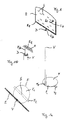
- FIG. 1 shows a perspective view of the goods display system according to the invention, consisting of the base F, the pipe connecting element V and the goods display element E.
- the foot F has the two foot elements F 1 and F 2 , which by means of a screw, snap, plug or bayonet connection can be connected or connected with each other.
- the upper foot element F 1 has a holding device F F , on or in which the connecting element V in the form of a tubular hollow profile with its lower end can be inserted or fastened.
- the two foot elements F 1 and F 2 are mutually rotatable and can, depending on the design of the base generate a clamping force, by means of which a particular upper beam P 3 a pallet (see FIG.
- the connecting element V At the top of the connecting element V is a rod E st , which is connected to the goods display or goods presentation element E or its frame E R , inserted.
- the goods presentation element E is rotatably supported relative to the connecting element V by means of the bearing D.
- different plate elements Ep of the goods presentation element E can be inserted from above, which may have, for example, a different arrangement of the holes.
- the frame E R is U-shaped.
- the plate E p has holes L, in the holder E H are fastened, to which in turn goods or packaging can be fastened, as shown in Figure S.
- FIG. 1a shows a plan view of the goods presentation system according to FIG. 1
- the lower foot member F 2 is rod-shaped and connected via the screw S with the upper foot member F 1 or connectable.
- the lower foot element has a through hole with a corresponding internal thread.
- the fastening device F F is off-center, in particular arranged on the edge of the circular or disk-shaped upper foot element F 1 , so that it can be arranged centrally, ie in the middle of the pallet.
- E S is also possible that the fixing device F F in the middle or any other part of the foot member F 1 is arranged.
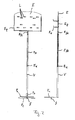
- FIG. 2 shows a front and a cross-sectional view of the goods display system according to the FIG. 1 ,
- the rod E st is telescopically from the connecting element Vshi- or inserted, so that the goods display element E can be locked at different heights above the pallet, at the same time the orientation of the goods display element E is arbitrary.
- the clamping device E K has correspondingly formed clamping means which are not centrally mounted on the rod E St.
- FIG. 3 shows the goods display system according to the invention, which is arranged on a pallet P, so that the goods display element E is arranged approximately above the center of the pallet P.
- the pallet is composed of the spacer blocks P 1 , the base beam P 2 and the upper beam P 3 and the crossbar F s .
- the upper bar P 3 form between them column P 4 through which the lower foot element F 2 can be pushed through with a corresponding embodiment. After passing through the lower foot element F 2 can be rotated transversely to the columns P 4 , after which then a clamping by means of the foot elements F 1 and F 2 can be produced, so that the goods display system is securely attached to the upper beam P 3 of the pallet P.
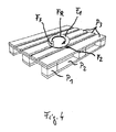
- FIG. 4 clarified by means of the arrow F R, the direction of rotation in which the upper foot member F 1 must be rotated relative to the lower foot member F 2 , so that the clamping is generated.
- To attach the goods display element E can be removed together with the connecting pipe V from the foot F, so that easier handling is given.
- FIG. 5 shows a pallet P stacked with packages P A. Between the packages P A , the connecting pipe V protrudes upward beyond the upper packages, so that the goods display element E together with the goods W attached thereto is visible from all sides and the customers the goods W can optionally remove from the goods display system.
Landscapes
- Pallets (AREA)
- Display Racks (AREA)
Abstract
Description
- Die vorliegende Erfindung betrifft ein Warendisplaysystem für eine Palette, einen Standfuß und ein Warenpräsentationselement aufweisend, wobei das Warenpräsentationselement mittels mindestens eines stabförmigen Verbindungselements über dem Standfuß gehalten ist.
- Waren bzw. deren Verpackungen werden in der Regel in Regalen aufeinander gestapelt oder können an Haken, welche an Wänden befestigt bzw. befestigbar sind, aufgehängt werden. Darüber hinaus existieren noch Hinweisschilder, die meist einen Standfuß aufweisen und neben einer Palette platzierbar sind. An diese Tafeln sind Werbeplakate oder Abbildungen der auf der danebenstehenden Palette gestapelten Waren anbringbar oder aber als kartonierte Platten einschiebbar. Die Schilder können auch über einen Standfuß verfügen, mit dem sie oben auf die auf der Palette gestapelte Ware platzierbar sind, so dass der Käufer auch von weitem sofort den Lagerort der Ware und deren Preis erkennt. Nachteilig hierbei ist, dass die Schilder leicht umfallen können, und bei der Anordnung der Schilder auf der auf der Palette gestapelten Ware vom Käufer stets umgestellt werden müssen, damit der unter dem Schild befindliche Warenkarton von der Palette herabnehmbar ist.
- Aufgabe der vorliegenden Erfindung ist es, ein Warendisplaysystem für eine Palette bereit zu stellen, an dem nicht nur Abbildungen und Preise der gestapelten Waren anzeigbar bzw. befestigbar sind, sondern das auch eine hohe Standfestigkeit aufweist.
- Diese Aufgabe wird erfindungsgemäß dadurch gelöst, dass der Standfuß des Warendisplaysystems an der Palette befestigbar ist und dass das Warenpräsentationselement Mittel zum Befestigen von Waren und/oder Verpackungen aufweist. Vorteilhafte Ausgestaltungen ergeben sich durch die Merkmale der Unteransprüche.
- Der Erfindung liegt der Gedanke zugrunde, ein Warendisplaysystem bereit zu stellen, an dem Waren und/oder Zubehör für die auf der Palette gestapelten Waren befestigbar und vom Käufer abnehmbar sind, wobei gleichzeitig gewährleistet ist, dass das Warendisplaysystem fest mit der Palette verbunden ist, so dass ein Umkippen des Warendisplaysystems, auch wenn keine oder nur wenige Warenkartons auf der Palette gestapelt sind, sicher vermieden wird.
- Das Warendisplaysystem weist vorteilhaft einen Klemmmechanismus auf, mit dem es an der Palette befestigbar ist, so dass die Palette selbst nicht beschädigt wird. Ein schnelles Lösen der Klemmvorrichtung ermöglicht den schnellen Auf- und Abbau des Warendisplaysystems bzw. dessen Standfuß und Ständer. Besonders vorteilhaft ist es, wenn das Klemmsystem aus zwei Fußelementen besteht, die mittels einer Verschraubung oder z. B. einem Bajonettverschluss miteinander verbindbar sind, wobei mit der Verbindung eine Klemmkraft erzeugbar ist, durch die ein Teil der Palette insbesondere die oberen Tragbalken zwischen den Fußelementen eingeklemmt werden. Das untere Fußelement muss somit lediglich unter die oberen Tragbalken platziert werden, wonach dann durch eine Relativbewegung der Fußelemente zueinander die klemmende Kraft erzeugbar ist.
- Das untere Fußelement ist in einer besonders bevorzugten Ausführungsform des erfindungsgemäßen Warendisplaysystems als schmale Strebe ausgebildet, die durch die oberen Balken der Palette gebildeten Spalte von oben durchsteckbar ist. Durch Verdrehen des durchgesteckten Fußelementes ist dieses verliersicher unterhalb der oberen Tragbalken der Palette angeordnet, wonach dann durch eine Drehbewegung des oberen Fußelementes relativ zum unterem Fußelement die Klemmkraft erzeugbar ist. Durch Verstellen der Fußelemente relativ zueinander in die entgegengesetzte Richtung, kann die Klemmkraft gelöst werden. Nach Lösen der Klemmkraft kann durch Drehen des gesamten Warendisplaysystems das untere Fußelement wieder so verstellt werden, dass es durch die Balken der Palette nach oben herausnehmbar ist. In diesem Fall ist lediglich eine Schraubverbindung zwischen den beiden Fußelementen vorzusehen, wobei eines der Fußelemente ein Innengewinde aufweisen muss, welches mit einer in dem anderen Fußelement fest angeordneten Gewindestange zusammenwirkt. Selbstverständlich ist es möglich, dass der Standfuß gesondert vom Warendisplayelement an der Palette befestigt wird, wonach dann das Warendisplayelement an dem Standfuß befestigt wird.
- In einer weiteren möglichen Ausführungsform weist das unter die Palette anzuordnende Fußelement eine Form auf, durch die es auf dem Boden, auf dem auch die Palette aufliegt, auflegbar ist. In diesem Falle muss lediglich ein den Spalt durchgreifendes Verbindungselement, welches mit dem oberen Fußelement verbunden ist, mit dem unteren Fußelement verbunden werden.
- Es ist auch möglich, dass zwei Verbindungsmittel zwischen dem oberen und dem unteren Fußelement vorgesehen sind, die entweder durch den gleichen oder nebeneinander angeordnete Spalte der Palette durchgreifen und mit dem unteren Fußelement, welches unter der Palette platzierbar ist, verbindbar, insbesondere in dieses einsteckbar sind. Vorteilhaft ist hier eine Rastverbindung vorzusehen, die durch eine erhöhte Kraft entgegen der Verrastung, d. h. senkrecht nach oben, wieder lösbar ist.
- Das Warendisplayelement kann Löcher und/oder Haken aufweisen, wobei in die Löcher z. B. Haken einhängbar sind, an die wiederum Waren oder Verpackungen anhängbar sind. Vorteilhaft ist das Warendisplayelement drehbar an dem Verbindungselement gelagert, so dass es in jede gewünschte Position relativ zur Palette verdrehbar ist.
- In einer weiteren vorteilhaften Ausführungsform ist das Warendisplayelement relativ zum Standfuß mittels eines Teleskopsystems in der Vertikalen verstellbar und in jeder beliebigen Höhe arretierbar, so dass es den jeweiligen Gegebenheiten entsprechend in der jeweils gewünschten und erforderlichen Höhe positionier bzw. arretierbar ist.
- Nachfolgend wird das erfindungsgemäße Warendisplaysystem anhand von Zeichnungen näher erläutert.
- Es zeigen:
- Figur 1:
- Perspektivische Darstellung des erfindungsgemäßen Warenpräsentationssystems;
- Figur 1a:
- Draufsicht auf das Warenpräsentationssystem gemäß
Figur 1 ; - Figur 1b:
- Detaildarstellung der Befestigung des Warenpräsentationselements an dem Verbindungsmittel;
- Figur 2:
- Vorderansicht und Querschnittsdarstellung des Warenpräsentationssystems gemäß
Figur 1 ; - Figur 3:
- auf einer Palette befestigtes Warendisplaysystem gemäß der
Figuren 1 und2 ; - Figur 4:
- Palette mit darauf befestigten Standfuß;
- Figur 5:
- Palette mit daran befestigten Warendisplaysystem und gestapelten Verpackungskartons;
- Die
Figur 1 zeigt eine perspektivische Ansicht des erfindungsgemäßen Warendisplaysystems, bestehend aus dem Standfuß F, dem Rohrverbindungselement V und dem Warenpräsentationselement E. Der Standfuß F weist die beiden Fußelemente F1 und F2 auf, welche mittels einer Schraub-, Schnapp-, Steck- oder Bajonett- verbindung miteinander verbindbar bzw. verbunden sind. Das obere Fußelement F1 weist eine Haltevorrichtung FF auf, an bzw. in der das Verbindungselement V in Form eines röhrenförmigen Hohlprofils mit seinem unteren Ende einsteckbar bzw. befestigbar ist. Die beiden Fußelemente F1 und F2 sind zueinander verdrehbar und können, je nach Ausbildung des Standfußes eine Klemmkraft erzeugen, mittels derer ein insbesondere oberer Balken P3 einer Palette (sieheFigur 3 ) einklemmbar ist, so dass das Warendisplaysystem sicher an der Palette befestigt ist. Oben in das Verbindungselement V ist eine Stange Est, welche mit dem Warendisplay- bzw. Warenpräsentationselement E bzw. dessen Rahmen ER verbunden ist, einschiebbar. Das Warenpräsentationselement E ist mittels des Lagers D drehbar gegenüber dem Verbindungselement V gelagert. In den Rahmen ER können verschiedene Plattenelemente Ep des Warenpräsentationselementes E von oben eingeschoben werden, welche z.B. eine unterschiedliche Anordnung der Löcher aufweisen können. Hierzu ist der Rahmen ER u-förmig ausgebildet. Die Platte Ep weist Löcher L auf, in die Halter EH befestigbar sind, an denen wiederum Waren oder Verpackungen befestigbar sind, wie es in Figur S dargestellt ist. - Die
Figur 1a zeigt eine Draufsicht auf das Warenpräsentationssystem gemäßFigur 1 . Das untere Fußelement F2 ist stabförmig ausgebildet und über die Schraubverbindung S mit dem oberen Fußelement F1 verbunden bzw. verbindbar. Das untere Fußelement weist hierzu ein Durchgangsbohrung mit korrespondierendem Innengewinde auf. Die Befestigungsvorrichtung FF ist außermittig, insbesondere am Rand des kreis- bzw. scheibenförmig ausgebildeten oberen Fußelementes F1 angeordnet, so dass sie zentrisch, d. h. in der Mitte der Palette anordbar ist. ES ist jedoch auch möglich, dass die Befestigungsvorrichtung FF in der Mitte oder jeder anderen Stelle des Fußelements F1 angeordnet ist. - Die
Figur 2 zeigt eine Vorder- und eine Querschnittsdarstellung des Warendisplaysystems gemäß derFigur 1 . Die Stange Est ist teleskopartig aus dem Verbindungselement V heraus- bzw. einschiebbar, so dass das Warenpräsentationselement E in verschiedenen Höhen oberhalb der Palette arretierbar ist, wobei gleichzeitig die Ausrichtung des Warenpräsentationselementes E frei wählbar ist. Die Klemmvorrichtung EK weist hierfür entsprechend ausgebildete nicht zentrisch an der Stange ESt befestigte Klemmmittel auf. - Die
Figur 3 zeigt das erfindungsgemäße Warendisplaysystem, welches auf einer Palette P angeordnet ist, so dass das Warenpräsentationselement E ungefähr über der Mitte der Palette P angeordnet ist. Die Palette ist aus den Abstandsklötzen P1, den Grundbalken P2 und den oberen Balken P3 sowie den Querbalken Fs zusammengesetzt. Die oberen Balken P3 bilden zwischen sich Spalte P4 durch die bei entsprechender Ausgestaltung das untere Fußelement F2 durchsteckbar ist. Nach dem Durchstecken kann das untere Fußelement F2 quer zu den Spalten P4 verdreht werden, wonach dann eine Klemmung mittels der Fußelemente F1 und F2 herstellbar ist, so dass das Warendisplaysystem sicher an den oberen Balken P3 der Palette P befestigt ist. - Die
Figur 4 verdeutlicht mittels des Pfeils FR die Drehrichtung, in der das obere Fußelement F1 gegenüber dem unteren Fußelement F2 verdreht werden muss, damit die Klemmung erzeugt wird. Zum Befestigen kann das Warenpräsentationselement E zusammen mit dem Verbindungsrohr V vom Fußelement F abgenommen werden, damit eine leichtere Handhabbarkeit gegeben ist. - Die
Figur 5 zeigt eine mit Packungen PA bestapelte Palette P. Zwischen den Verpackungen PA ragt das Verbindungsrohr V nach oben über die oberen Verpackungen hinaus, so dass das Warenpräsentationselement E zusammen mit den an ihm befestigten Waren W von allen Seiten sichtbar ist und die Kunden die Waren W wahlweise vom Warendisplaysystem abnehmen können.
Claims (9)
- Warendisplaysystem für eine Palette (P), einen Standfuß (F) und ein Warenpräsentationselement (E) aufweisend, wobei das Warenpräsentationselement (E) mittels mindestens eines stabförmigen Verbindungselements (V) über dem Standfuß (F) gehalten ist, dadurch gekennzeichnet, dass der Standfuß (F) an der Palette (P) befestigbar ist, und dass das Warenpräsentationselement (E) Mittel (L, EH) zum Befestigen von Waren und/oder Verpackungen (W) aufweist.
- Warendisplaysystem nach Anspruch 1, dadurch gekennzeichnet, dass der Standfuß (F) zwei miteinander verbindbare Fußelemente (F1, F2) aufweist, wobei das erste Fußelement (F1, F2) auf die Oberseite der Palette (P) aufsetzbar ist und das zweite Fußelement (F2) an der Unterseite der Palette (P) anordbar ist.
- Warendisplaysystem nach Anspruch 2, dadurch gekennzeichnet, dass die Fußelemente (F1, F2) mit einer Verschraubung (S) miteinander verbindbar sind, wobei die Fußelemente (F1, F2) mindestens ein Teil der Palette (P3) zwischen sich einklemmen.
- Warendisplaysystem nach einem der Ansprüche 1 bis 3, dadurch gekennzeichnet, dass das Warenpräsentationselement (E) relativ zum Standfuß (F) drehbar ist.
- Warendisplaysystem nach Anspruch 4, dadurch gekennzeichnet, dass das Warenpräsentationselement (E) mittels eines Drehlagers (D) am Verbindungselement (V) gelagert ist.
- Warendisplaysystem nach einem der vorhergehenden Ansprüche, dadurch gekennzeichnet, dass das Warenpräsentationselement (E) durch eine Platte gebildet ist, die insbesondere fensterartige Öffnungen (L), z.B. in Form von Löchern oder Schlitzen, aufweist, in denen Halter (EH) für Waren (W) befestigbar sind.
- Warendisplaysystem nach einem der vorhergehenden Ansprüche, dadurch gekenntzeichnet, dass das Verbindungselement (V) ein Rohr ist, in dem von oben ein am Warenpräsentationselement (E) befestigte Stange (EST) einschiebbar ist, und das Verbindungselement (V) und die Stange (EST) teleskopartig ineinander schiebbar sind..
- Warendisplaysystem nach Anspruch 7, dadurch gekennzeichnet , dass die Stange (EST) drehbar in dem Rohr (V) gelagert ist und ein Klemmelement (EK) aufweist, mit dessen Hilfe die Stange (EST) und das Rohr (V) in beliebigen Positionen zueinander arretierbar sind.
- Warendisplaysystem nach einem der vorhergehenden Ansprüche, dadurch gekenntzeichnet, dass das Warenpräsentationselement (E) einen Rahmen (ER) und eine darin befestigbare, insbesondere einschiebbare Präsentationsplatte (Ep) aufweist, wobei die Präsentationsplatte (EP) Halter (EH) für Waren (W) und/oder fensterartige Öffnungen (L), z.B, in Form von Löchern oder Schlitzen, aufweist, und in den Öffnungen (L) Halter (EH) für Waren (W) befestigbar sind.
Applications Claiming Priority (1)
| Application Number | Priority Date | Filing Date | Title |
|---|---|---|---|
| DE200810029938 DE102008029938A1 (de) | 2008-06-26 | 2008-06-26 | Warendisplaysystem für eine Palette |
Publications (2)
| Publication Number | Publication Date |
|---|---|
| EP2138073A2 true EP2138073A2 (de) | 2009-12-30 |
| EP2138073A3 EP2138073A3 (de) | 2012-10-10 |
Family
ID=41165345
Family Applications (1)
| Application Number | Title | Priority Date | Filing Date |
|---|---|---|---|
| EP09007410A Withdrawn EP2138073A3 (de) | 2008-06-26 | 2009-06-04 | Warendisplaysystem für eine Palette |
Country Status (2)
| Country | Link |
|---|---|
| EP (1) | EP2138073A3 (de) |
| DE (1) | DE102008029938A1 (de) |
Family Cites Families (7)
| Publication number | Priority date | Publication date | Assignee | Title |
|---|---|---|---|---|
| US3917072A (en) * | 1975-01-15 | 1975-11-04 | Commercial Wire And Display Pr | Upright revolving display rack |
| DE8801144U1 (de) * | 1988-02-01 | 1988-04-28 | Torfstreuverband Gmbh, 2900 Oldenburg | Vorrichtung zur Präsentation von Anzeigemitteln |
| DE29704265U1 (de) * | 1997-03-08 | 1997-05-15 | Kessler, Heiko, 75223 Niefern-Öschelbronn | Ausstellungs- und Verkaufsstand |
| DE20218276U1 (de) * | 2002-11-25 | 2003-02-27 | Fritz Fries + Söhne GmbH + Co, 55743 Idar-Oberstein | Warenpräsentation und Verkaufsregal |
| DE20308032U1 (de) * | 2003-05-22 | 2004-09-23 | Melitta Haushaltsprodukte Gmbh & Co. Kg | Präsentationsständer |
| AU2005100503A4 (en) * | 2005-02-01 | 2005-07-21 | Adline Group Pty Limited | Multi-functional System |
| DE102007005482A1 (de) * | 2007-01-30 | 2008-07-31 | Wanzl Metallwarenfabrik Gmbh | Verkaufsständer |
-
2008
- 2008-06-26 DE DE200810029938 patent/DE102008029938A1/de not_active Withdrawn
-
2009
- 2009-06-04 EP EP09007410A patent/EP2138073A3/de not_active Withdrawn
Also Published As
| Publication number | Publication date |
|---|---|
| EP2138073A3 (de) | 2012-10-10 |
| DE102008029938A1 (de) | 2009-12-31 |
Similar Documents
| Publication | Publication Date | Title |
|---|---|---|
| EP3712354A1 (de) | Schalungsbühne | |
| DE1941854A1 (de) | Stellage fuer stangenfoermiges Material | |
| EP0158368B1 (de) | Aus Einzelelementen zusammensetzbares Gestell für Notstrombatterien | |
| DE102006039569B4 (de) | Verbindungselement, Verbindungssystem, Systemmöbelelement sowie Systemmöbeltisch | |
| DE3822455C2 (de) | Vorrichtung zur Präsentation von Zweirädern | |
| DE102008029938A1 (de) | Warendisplaysystem für eine Palette | |
| DE10038223B4 (de) | Klapptisch | |
| EP1421877B1 (de) | Möbel unter Verwendung von Recycling-Kunststoff | |
| DE10133951B4 (de) | Theke | |
| DE19956951C2 (de) | Arbeitsplatzmöbel mit einem Möbelgestell aus vertikalen Säulen und Quertraversen | |
| EP0582104A2 (de) | Verkaufshilfe | |
| DE202004002782U1 (de) | Verkaufseinrichtung | |
| DE202010010429U1 (de) | Vorrichtung zur Verlängerung eines Möbelfußes eines Möbelstücks | |
| EP1749459A1 (de) | Vorrichtung zur Aufbewahrung wenigstens eines kastenförmigen Gegenstandes | |
| DE10058376B4 (de) | Präsentationsständer für Druckerzeugnisse | |
| AT226404B (de) | Auslegerkonstruktion | |
| DE102010033910B4 (de) | Aufhängevorrrichtung zum temporären Verbinden von Kragarmen | |
| DE4411603C2 (de) | Standkonsole für Heizkörper | |
| DE3429336A1 (de) | Verkaufs- oder praesentationsregal | |
| DE29602473U1 (de) | Präsentationsvorrichtung | |
| WO2007009604A1 (de) | Regallager | |
| EP2223631B1 (de) | Regal, insbesondere Schiffsregal, mit mindestens einer Schlingerleiste mit insbesondere mechanischer Sicherung, und Vorrichtung zur Sicherung der Lage eines Endes einer Schlingerleiste von einem Regal, insbesondere von einem Schiffsregal | |
| DE29712525U1 (de) | Tragvorrichtung, insbesondere für Regale o.dgl. | |
| DE202006003845U1 (de) | Zerlegbares Regal | |
| WO2012113091A1 (de) | Gestellaufbau zur warenpräsentation |
Legal Events
| Date | Code | Title | Description |
|---|---|---|---|
| PUAI | Public reference made under article 153(3) epc to a published international application that has entered the european phase |
Free format text: ORIGINAL CODE: 0009012 |
|
| AK | Designated contracting states |
Kind code of ref document: A2 Designated state(s): AT BE BG CH CY CZ DE DK EE ES FI FR GB GR HR HU IE IS IT LI LT LU LV MC MK MT NL NO PL PT RO SE SI SK TR |
|
| PUAL | Search report despatched |
Free format text: ORIGINAL CODE: 0009013 |
|
| AK | Designated contracting states |
Kind code of ref document: A3 Designated state(s): AT BE BG CH CY CZ DE DK EE ES FI FR GB GR HR HU IE IS IT LI LT LU LV MC MK MT NL NO PL PT RO SE SI SK TR |
|
| AX | Request for extension of the european patent |
Extension state: AL BA RS |
|
| RIC1 | Information provided on ipc code assigned before grant |
Ipc: A47F 5/02 20060101ALN20120831BHEP Ipc: A47F 5/01 20060101AFI20120831BHEP |
|
| STAA | Information on the status of an ep patent application or granted ep patent |
Free format text: STATUS: THE APPLICATION IS DEEMED TO BE WITHDRAWN |
|
| 18D | Application deemed to be withdrawn |
Effective date: 20130411 |