EP2136018B1 - Dispositif de verrouillage en particulier pour des couvercles, bouchons et ailes de porte ou de fenêtre - Google Patents
Dispositif de verrouillage en particulier pour des couvercles, bouchons et ailes de porte ou de fenêtre Download PDFInfo
- Publication number
- EP2136018B1 EP2136018B1 EP09466007.3A EP09466007A EP2136018B1 EP 2136018 B1 EP2136018 B1 EP 2136018B1 EP 09466007 A EP09466007 A EP 09466007A EP 2136018 B1 EP2136018 B1 EP 2136018B1
- Authority
- EP
- European Patent Office
- Prior art keywords
- pinion
- teethed
- locking
- pin
- locking device
- Prior art date
- Legal status (The legal status is an assumption and is not a legal conclusion. Google has not performed a legal analysis and makes no representation as to the accuracy of the status listed.)
- Not-in-force
Links
Images


Classifications
-
- E—FIXED CONSTRUCTIONS
- E05—LOCKS; KEYS; WINDOW OR DOOR FITTINGS; SAFES
- E05C—BOLTS OR FASTENING DEVICES FOR WINGS, SPECIALLY FOR DOORS OR WINDOWS
- E05C1/00—Fastening devices with bolts moving rectilinearly
- E05C1/02—Fastening devices with bolts moving rectilinearly without latching action
- E05C1/06—Fastening devices with bolts moving rectilinearly without latching action with operating handle or equivalent member moving otherwise than rigidly with the bolt
-
- E—FIXED CONSTRUCTIONS
- E02—HYDRAULIC ENGINEERING; FOUNDATIONS; SOIL SHIFTING
- E02D—FOUNDATIONS; EXCAVATIONS; EMBANKMENTS; UNDERGROUND OR UNDERWATER STRUCTURES
- E02D29/00—Independent underground or underwater structures; Retaining walls
- E02D29/12—Manhole shafts; Other inspection or access chambers; Accessories therefor
- E02D29/14—Covers for manholes or the like; Frames for covers
- E02D29/1427—Locking devices
-
- E—FIXED CONSTRUCTIONS
- E05—LOCKS; KEYS; WINDOW OR DOOR FITTINGS; SAFES
- E05B—LOCKS; ACCESSORIES THEREFOR; HANDCUFFS
- E05B13/00—Devices preventing the key or the handle or both from being used
- E05B13/002—Devices preventing the key or the handle or both from being used locking the handle
- E05B13/004—Devices preventing the key or the handle or both from being used locking the handle by locking the spindle, follower, or the like
-
- E—FIXED CONSTRUCTIONS
- E05—LOCKS; KEYS; WINDOW OR DOOR FITTINGS; SAFES
- E05B—LOCKS; ACCESSORIES THEREFOR; HANDCUFFS
- E05B9/00—Lock casings or latch-mechanism casings ; Fastening locks or fasteners or parts thereof to the wing
- E05B9/08—Fastening locks or fasteners or parts thereof, e.g. the casings of latch-bolt locks or cylinder locks to the wing
-
- E—FIXED CONSTRUCTIONS
- E05—LOCKS; KEYS; WINDOW OR DOOR FITTINGS; SAFES
- E05B—LOCKS; ACCESSORIES THEREFOR; HANDCUFFS
- E05B35/00—Locks for use with special keys or a plurality of keys ; keys therefor
- E05B35/008—Locks for use with special keys or a plurality of keys ; keys therefor for simple tool-like keys
-
- E—FIXED CONSTRUCTIONS
- E05—LOCKS; KEYS; WINDOW OR DOOR FITTINGS; SAFES
- E05B—LOCKS; ACCESSORIES THEREFOR; HANDCUFFS
- E05B63/00—Locks or fastenings with special structural characteristics
- E05B63/14—Arrangement of several locks or locks with several bolts, e.g. arranged one behind the other
- E05B63/143—Arrangement of several locks, e.g. in parallel or series, on one or more wings
Definitions
- the inventions relates to a locking device, especially for covers, caps, door and window wings, the locking device comprising a case having a bottom and a cap, wherein a toothed pinion is pivoted inside the case and tangentially slidingly thereto a locking pin is arranged in the case.
- the objective of the invention is to provide a locking device, especially for covers, caps, door and window wings, comprising safety elements for preventing any undesirable manipulation, being of a relatively small size and easily mounted and comprising a small number of components, thus favourably effecting the production costs.
- the locking device has to be suitable for covers located in roadways, too, i.e. in a place substantially polluted by a mixture of water, sand and other mechanical dirt.
- a locking device especially for covers, caps, door and window wings, comprising a case having a bottom and a cover, wherein a teethed pinion is pivoted inside the case and tangentially slidingly thereto a locking pin is arranged, wherein according to the invention a circular socket is arranged at least in the bottom, the teethed pinion is pivoted in the circular socket, an axially shifting control pin is arranged in the axis of the teethed pinion and wherein a longitudinal socket is arranged at least in the bottom and oriented tangentially with respect to the teethed pinion, the locking pin being arranged slidingly in the longitudinal socket and being provided at its central part with annular notches by means of which the locking pin engages the respective teeth of the teethed pinion.
- control pin is provided with two adapted ends, wherein a driver is fixed on the first adapted end, the driver having a shaped head for a control key provided with a complementary shaped hollow and the second adapted end is provided with a transversally arranged securing pin for an engagement with stop noses formed outside the bottom of the case uniformly around a bearing aperture of the control pin, wherein the central part of the control pin is provided with a carrier collar for a pressure spring arranged between the carrier collar and the teethed pinion.
- first adapted end of the control pin with a pair of mutually parallel flattened surfaces so that the driver having a complementary shaped hollow may be set thereon forming a fixed joint and to provide the second adapted end of the control pin with another pair of mutually parallel flattened surfaces so that the teethed pinion having a complementary shaped through-hole may be set thereon forming a fixed joint.
- the locking pin with an elongated end behind the last annular notch to stop the action of the teethed pinion in the locked position by an engagement of its respective tooth with the cylindrical surface of the elongated end and with a locking part before the first annular notch for stopping the action of the teethed pinion in the unlocked position by an engagement of its respective tooth with the cylindrical surface of the locking part of the locking pin.
- stop noses are also advantageous to form stop noses as a part of the bottom of the case by bending the material out of the bearing aperture.
- the locking device according to the invention may comprise longer screws with spacing bushings to mount it spaced from the cover and with pressure springs arranged between the head of a longer screw and the bottom of the case for a tighter attachment of the cover to the frame optionally using a seal.
- An advantage of the locking device according to the invention is that the teeth of the teethed pinion are engaged permanently and with the annular notches of the locking device so that it is not necessary to assure the position of the teethed pinion.
- the teethed pinion is arranged in the case to pivot only and not to be height adjusted the height of the case could be reduced considerably. It is especially advantageous that for any unauthorised person the unlocking of the cover is made difficult by the code of the key and by the shaped head of the driver as well by the stop noses outside the bottom of the case which are intended for the engagement with the securing pin.
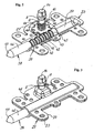
- FIG. 1 depicts an axonometric bottom view of the exploded locking device
- Fig. 2 depicts an axonometric top view of the bottom of the locking device in the locked position, the cover being removed from the case
- Fig. 3 depicts an axonometric top view of the closed case of the locking device
- Fig. 4 depicts an axonometric bottom view of the sewer cover in a frame with an installed locking device
- Fig. 5 depicts an enlarged bottom view of the locking device installed on the sewer cover
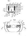
- Fig. 6 depicts a cross sectional view of a part of the sewer cover and of its frame with a part of the locking device taken along line VI-VI in Fig.
- Fig. 7 depicts a cross sectional view of the locking device mounted on the sewer cover by means of spacing bushings, springs and longer screws, taken along the line VII-VII in Fig. 8 but revolved, for 180°
- Fig. 8 depicts a bottom view of a circular sewer cover inserted into a frame and provided with a pair of locking devices.
- the locking device especially for covers, caps, door and window wings, i.e. covers 1 , comprises a control pin 2 having cylindrical form with two adapted ends 3, 4 and provided with a carrier collar 5 in the middle part of the control pin 2 .
- the first adapted end 3 of the control pin 2 is provided with a pair of flattened surfaces 6 , 7 which are parallel to each other, to be inserted into a driver 8 having a complementary cavity 9 to form a fixed joint; and the second adapted end 4 of the control pin 2 is provided with another pair of flattened surfaces 10 . 11 which are parallel to each other, to be inserted into a teethed pinion 12 having a complementary through-hole 13 to form a fixed joint.
- the driver 8 is provided with a shaped head 14 to be inserted into a control key 15 , e.g., a tackle key, as shown partially in Fig. 6 .
- the first adapted end 3 of the control pin 2 is provided with a lateral through hole 16 and the driver 8 is provided with a corresponding lateral opening 17, too, to be connected with a safety pin 18.
- the second adapted end 4 of the control pin 2 has got at its end another lateral through opening 19 for a securing pin 20 .
- the teethed pinion 12 is mounted on the second end 4 of the control pin 2 and a pressure spring 21 is set on the control pin 2 between said teethed pinion 12 and the carrier collar 5 .
- the assembly as described above is arranged in a case 22 ( Fig. 3 ) consisting of a bottom 23 and a cover 24 , wherein the circumferential edge 25 of the cover 24 corresponds to the circumferential edge 26 of the bottom 23 .
- the teethed pinion 12 is floating in a circular socket 27 ( Fig. 2 ) formed in the bottom 23 of the case 22 and the second adapted end 4 of the control pin 2 goes through a bearing aperture 28 ( Fig. 1 ) formed in the bottom 23 of the case 22 .
- Four evenly spaced stop noses 29, 30, 31 , 32 are formed around the bearing aperture 28 outside the bottom 23 . e.g. by bending out its material.
- Gaps 33 , 34 , 35 , 36 between those are intended for an insertion of the securing pin 20 .
- the bottom 23 of the case 22 is provided with a longitudinal socket 37 arranged tangentially with respect to the circular socket 27 and intended for a locking pin 38 . which has got a cylindrical form and a part of the locking pin 38 is provided with annular notches 39 , 40 , 41 , 42, 43 for the engagement with the teeth 44 of the teethed pinion 12 .
- the locking pin 38 has got an extended end 45 behind the last annular notch 43 , the extended end 45 being intended for stopping the motion of the teethed pinion 12 in the locked position by the engagement of its respective tooth 44 with the cylindrical surface of the extended end 45 , and it has got a locking part 46 before the first annular notch 36 for stopping the motion of the teethed pinion 12 in the unlocked position by the engagement of its respective tooth 44 with the cylindrical surface of the locking part 46 .
- the free end of the locking pin 38 is provided with a taper 47 having a conical or spherical form.
- the cover 24 is provided with a circular socket 27a formed according to the inner components and a longitudinal socket 37a for the locking pin 38 .
- the cover 24 is connected with the bottom 23 by means of rivets 48 ( Fig. 3 ).
- the driver 8 with a part of the control pin 2 extends beyond the cover 24 .
- the cover 24 may be flat without the circular socket 27a and without the longitudinal socket 37a, in case the circular socket 27 and the longitudinal socket 37 in the bottom 23 are of deeper form.
- the locking device is to be mounted on the lower side of the cover 1 at its edge so that the locking pin 38 immediately after it has started shifting out of the case 22 gets into the locking aperture 49 in the frame 50 , which is mounted e.g. in a roadway (not shown).
- the opposite end 51 of the cover 1 may be provided with another locking device 52, as shown in Fig. 8 or with at least one bolt 53
- the exemplifying embodiment of Fig. 4 comprises two bolts 53 .
- the cover 1 is inserted into the frame 50 with its opposite end 51 first so that the bolt 53 gets under the lower edge of the frame 50 and then the insertion of the cover 1 may be completed.
- the cover 1 is provided with an operational hole 54 above the driver 8 .
- the operational hole 54 being intended for an insertion of the control key 15 and for putting its shaped hollow 55 ( Fig. 6 ) on the shaped head 14 of the driver 8 .
- the shaped hollow 55 of the control key 15 and the shaped head 14 of the driver 8 have to be identical. But it is possible to use several alternative embodiments of the matched forms for various locking devices to ensure that it may be difficult for an unauthorised person to open the cover 1 . In this way the code of the whole locking device is formed.
- the locking device is fastened to the cover by means of screws 56 ( Fig. 5 ) driven into the cover 1 from the lower side. As shown in Fig. 7 the locking device and a possible another locking device 52 may also be spaced apart fastened to the cover 1 by means of longer screws 57 . Spacing bushings 58 may be applied on the longer screws 57 between the lower side of the cover 1 and the locking device and a possible another locking device 52 .
- a pad 60 is put under the head 59 of each longer screw 57 and a pressure spring 61 is mounted between the pad 60 and the bottom 23 of each locking device to enable a tighter fastening of the cover 1 during the locking by means of the locking pin 38 , e.g. into the seal 62 .
- the whole locking device is arranged under the cover 1 at a distance, its function is good even in an environment highly polluted with a mixture of water and dirt.
- the free space around the shaped head 14 of the driver 8 makes a smooth insertion of the control key 15 possible.
- the locking device according to the invention works as follows:
- the locking device is mounted on the cover 1 as shown in Fig. 7 . i.e. using the longer screws 57 with spacing bushings 58 and the pressure springs 61 .
- the locking pin 28 gets with its taper 47 under an edge of the frame 50 and moving further on the thicker locking part 46 of the locking pin 38 gets under the edge too.
- the case 22 of the locking device is shifted against the action of the pressure springs 61 , by means of which the cover 1 is more tightly pressed against the frame 50 which may be provided with a sealing 62 .
- the locking device especially for covers, caps, door and window wings, according to the invention may be used especially for sewer covers and manhole covers as a protecting element against vandalism, theft and for a protection of covers made of recyclable materials, especially plastics, which have got a low weight and therefore they may get released from the frames and may be drawn out of the frames if loaded by heavy motor vehicles.
- List of reference numerals 1 covers 48 rivet 2 control pin 49 locking aperture 3 first adapted end 50 frame 4 second adapted end 51 opposite end 5 carrier collar 52 another locking device 6 flattened surfaces 53 bolt 7 flattened surface 54 operational hole 8 driver 55 shaped hollow 9 shaped cavity 56 screw 10 flattened surface 57 longer screw 11 flattened surface 58 spacing bushing 12 teethed pinion 59 head 13 through-hole 60 pad 14 shaped head 61 pressure spring 15 control key 62 seal 16 through hole 17 opening 18 safety pin 19 through opening 20 securing pin 21 pressure spring 22 case 23 bottom 24 cover 25 circumferential edge 26 circumferential edge 27 circular socket 27a circular socket 28 bearing aperture 29 stop nose 30 stop nose 31 stop nose 32 stop nose 33 securing gap 34 securing gap 35 securing gap 36 securing gap 37 longitudinal socket 37a longitudinal socket 38 locking pin 39 annular notch 40 annular notch 41 annular notch 42 annular notch 43 annular notch 44 tooth 45 elongated end 46 locking part 47 taper
Landscapes
- Engineering & Computer Science (AREA)
- Mechanical Engineering (AREA)
- Environmental & Geological Engineering (AREA)
- Life Sciences & Earth Sciences (AREA)
- General Life Sciences & Earth Sciences (AREA)
- Mining & Mineral Resources (AREA)
- Paleontology (AREA)
- Civil Engineering (AREA)
- General Engineering & Computer Science (AREA)
- Structural Engineering (AREA)
- Lock And Its Accessories (AREA)
- Hinges (AREA)
Claims (5)
- Un dispositif de verrouillage, en particulier pour les couvercles, chapeaux, battants de portes et fenêtres, comprenant un boîtier (22) ayant un fond (23) et un couvercle (24), dans lequel un pignon denté (12) est logé de manière pivotante à l'intérieur du boîtier (22) et le pivot de verrouillage (38) est disposée tangentiellement de manière coulissante à celui-ci, et un logement circulaire (27) est disposée au moins dans le fond (23), et le pignon denté (12) est logé d'une manière pivotante dans le logement circulaire (27), un pivot de commande (2) est disposé de manière axialement coulissante dans l'axe du pignon denté (12), où un logement longitudinal (37) est disposé au moins dans le fond (23) et orienté tangentiellement par rapport au pignon denté (12), le pivot de verrouillage (38) étant arrangé de manière coulissante dans le logement longitudinal (37), caractérisé en ce que le pivot de verrouillage (38) est muni d'encoches annulaires (39, 40, 41, 42) en sa partie centrale, par moyen de lesquelles le pivot de verrouillage (38) est en prise avec les dents respectives (44) du pignon denté (12), le pivot de commande (2) est munie de deux extrémités adaptées, où un entraîneur (8) ayant une tête façonnée (14) pour une clé de commande (15) munie d'un creux de forme complémentaire (55) est fixé à la première extrémité adaptée (3) et la seconde extrémité adaptée (4) est munie d'une goupille de sécurité disposée transversalement (20) pour un contact avec les saillants d'arrêt (29, 30, 31, 32) formés à l'extérieur du fond (23) du boîtier (22) uniformément autour d'une ouverture de palier (28) du pivot de commande (2), où la partie centrale du pivot de commande (2) est munie d'un collet d'appui (5) pour une ressort de pression (21) disposé entre le collet d'appui (5) et le pignon denté (12).
- Le dispositif de verrouillage selon la revendication 1, caractérisé en ce que la première extrémité adaptée (3) du pivot de commande (2) est munie d'une paire de surfaces aplaties mutuellement parallèles (6, 7) de sorte que l'entraîneur (8) ayant un creux de forme complémentaire (9) puisse être fixé sur celle-ci pour former une liaison non rotative et la seconde extrémité adaptée (4) du pivot de commande (2) est munie d'une autre paire de surfaces aplaties mutuellement parallèles (10, 11) de sorte que le pignon denté (12) ayant un trou traversant (13) de forme complémentaire puisse être fixé sur celle-ci formant ainsi une liaison non rotatif.
- Le dispositif de verrouillage selon la revendication 1, caractérisé en ce que le pivot de verrouillage (38) comporte une extrémité de forme allongée (45) derrière la dernière encoche annulaire (43) pour arrêter l'action du pignon denté (12) dans la position verrouillée par le contact de sa dent respective (44) avec la surface cylindrique de l'extrémité allongée (45) et une section de verrouillage (46) avant la première encoche annulaire (39) pour arrêter l'action du pignon denté dans la position déverrouillée par le contact de sa dent respective (44) avec la surface cylindrique de la section de verrouillage (46) du pivot de verrouillage (38).
- Le dispositif de verrouillage selon la revendication 1, caractérisé en ce que les saillants d'arrêt (29, 30, 31, 32) forment une partie du fond (23) du boîtier (22) et qu'ils sont formés par cintrage du matériau en dehors de l'ouverture de palier (28).
- Le dispositif de verrouillage selon la revendication 1, caractérisé en ce qu'il comprend des vis plus longues (57) avec des douilles d'écartement (58) pour le monter espacé du couvercle (1) et avec des ressorts de pression (61) disposés entre la tête (59) d'une vis plus longue (57) et le fond (23) du boîtier (22) pour une fixation plus serrée du couvercle (1) sur le châssis (50), éventuellement à l'aide d'un joint d'étanchéité (62).
Priority Applications (2)
| Application Number | Priority Date | Filing Date | Title |
|---|---|---|---|
| SI200931137T SI2136018T1 (sl) | 2008-06-19 | 2009-06-15 | Zapiralna naprava, zlasti za pokrivne priprave, pokrove, vrata in okenska krila |
| PL09466007T PL2136018T3 (pl) | 2008-06-19 | 2009-06-15 | Urządzenie ryglujące, zwłaszcza dla pokryw, wiek, drzwi i skrzydeł okiennych |
Applications Claiming Priority (1)
| Application Number | Priority Date | Filing Date | Title |
|---|---|---|---|
| CZ20082048 | 2008-06-19 |
Publications (3)
| Publication Number | Publication Date |
|---|---|
| EP2136018A2 EP2136018A2 (fr) | 2009-12-23 |
| EP2136018A3 EP2136018A3 (fr) | 2013-07-24 |
| EP2136018B1 true EP2136018B1 (fr) | 2014-12-03 |
Family
ID=41128181
Family Applications (1)
| Application Number | Title | Priority Date | Filing Date |
|---|---|---|---|
| EP09466007.3A Not-in-force EP2136018B1 (fr) | 2008-06-19 | 2009-06-15 | Dispositif de verrouillage en particulier pour des couvercles, bouchons et ailes de porte ou de fenêtre |
Country Status (3)
| Country | Link |
|---|---|
| EP (1) | EP2136018B1 (fr) |
| PL (1) | PL2136018T3 (fr) |
| SI (1) | SI2136018T1 (fr) |
Families Citing this family (3)
| Publication number | Priority date | Publication date | Assignee | Title |
|---|---|---|---|---|
| DOP2013000151A (es) * | 2013-06-21 | 2014-03-16 | Enriquillo Manuel Romero Fernandez | Sistema de seguridad para tapas de alcantarillados y sistema soterrado |
| CN107905650A (zh) * | 2017-11-06 | 2018-04-13 | 陈永 | 一种程序式机械解锁装置 |
| IT201800009233A1 (it) * | 2018-10-08 | 2020-04-08 | Dsg Srl | Dispositivo di chiusura di pozzetti o simili |
Family Cites Families (9)
| Publication number | Priority date | Publication date | Assignee | Title |
|---|---|---|---|---|
| DE254340C (fr) * | ||||
| US46740A (en) * | 1865-03-07 | Improvement in bolts for doors | ||
| US1169659A (en) * | 1915-10-13 | 1916-01-25 | Clark N Lowell | Lock. |
| US4438962A (en) * | 1981-10-02 | 1984-03-27 | Emhart Industries, Inc. | Alternate manually and electrically actuated bolt |
| JPH0493423A (ja) * | 1990-08-08 | 1992-03-26 | Nejino Mizutani:Kk | 施錠装置 |
| JP2847435B2 (ja) * | 1990-12-28 | 1999-01-20 | 株式会社フジクラ | マンホール等の蓋の施錠装置 |
| FR2877970B1 (fr) * | 2004-11-16 | 2008-12-26 | Quesdeville Michel Sa | Dispositif d'actionnement d'un mecanisme de condamnation d'un ouvrant par poignee enfoncable, et ouvrant ainsi equipe |
| US7506904B2 (en) * | 2005-12-29 | 2009-03-24 | Bell Helicopter Textron Inc. | Door handle lock assembly with automatic lock and retract |
| WO2008112906A1 (fr) * | 2007-03-14 | 2008-09-18 | Telezygology, Inc. | Actionneur mécanique aligné |
-
2009
- 2009-06-15 PL PL09466007T patent/PL2136018T3/pl unknown
- 2009-06-15 EP EP09466007.3A patent/EP2136018B1/fr not_active Not-in-force
- 2009-06-15 SI SI200931137T patent/SI2136018T1/sl unknown
Also Published As
| Publication number | Publication date |
|---|---|
| EP2136018A2 (fr) | 2009-12-23 |
| EP2136018A3 (fr) | 2013-07-24 |
| PL2136018T3 (pl) | 2015-05-29 |
| SI2136018T1 (sl) | 2015-04-30 |
Similar Documents
| Publication | Publication Date | Title |
|---|---|---|
| EP3194696B1 (fr) | Poignée confortable à fleur de la surface | |
| US7522112B2 (en) | Roof antenna with protected access to a fastener through the cover | |
| EP1730371B1 (fr) | Fermeture quart de tour en deux parties | |
| EP2640608B1 (fr) | Dispositif de protection antivol pour un ensemble caméra | |
| DE102016114494A1 (de) | Türgriff mit einem bewegbaren Notöffnungselement | |
| DE112019002029T5 (de) | Elektrische Steckverbindung mit führungskurvengesteuerter Verriegelungsvorrichtung | |
| EP2920389B1 (fr) | Portière pour véhicule automobile | |
| WO2009049588A2 (fr) | Serrure de véhicule automobile renforcée | |
| EP2136018B1 (fr) | Dispositif de verrouillage en particulier pour des couvercles, bouchons et ailes de porte ou de fenêtre | |
| EP2518245A2 (fr) | Poignée avec un élément de sécurisation dont le moyen de fixation reste totalement à l'intérieur d'une pièce mobile | |
| DE102005010483A1 (de) | Mit einer zu sichernden Vorrichtung zusammenwirkende Sicherungseinrichtung | |
| EP1740422B1 (fr) | Serrure a barillet avec cle codee pour blocage de la colonne de direction et protection d'un vehicule a moteur contre le vol | |
| DE102007045515B4 (de) | Vorrichtung zur Aufnahme und Aufbewahrung eines Objekts, und Fahrzeug mit einer daran befestigten Vorrichtung | |
| DE19955693C2 (de) | Kraftfahrzeugtürverschluss | |
| EP2642049A2 (fr) | Manipulation d'un véhicule automobile doté d'un élément de recouvrement mobile | |
| DE102009007329B4 (de) | Sicherungsanordnung für einen Schachtdeckel | |
| CN109869052B (zh) | 锁具装置、防护系统及乘用车 | |
| DE102012000842B4 (de) | Türanordnung mit Diebstahlsicherungsvorrichtung | |
| EP1777038B1 (fr) | Clé codé pour une jante anti-vol | |
| EP4071327A1 (fr) | Dispositif mobile de sécurité | |
| EP0416448B1 (fr) | Système de verrouillage, notamment pour portes va-et-vient d'omnibus ouvrant vers l'extérieur | |
| EP2423391B1 (fr) | Dispositif de fermeture pour couvercle de logement ou avaloir | |
| DE102008063495B4 (de) | Sicherungsvorrichtung für ein durch ein Schloss verschließbares Bauteil | |
| DE102012103936A1 (de) | Abdeckelement für eine Griffeinheit | |
| EP0952287A1 (fr) | Serrure, notamment sur une porte de véhicule |
Legal Events
| Date | Code | Title | Description |
|---|---|---|---|
| PUAI | Public reference made under article 153(3) epc to a published international application that has entered the european phase |
Free format text: ORIGINAL CODE: 0009012 |
|
| AK | Designated contracting states |
Kind code of ref document: A2 Designated state(s): AT BE BG CH CY CZ DE DK EE ES FI FR GB GR HR HU IE IS IT LI LT LU LV MC MK MT NL NO PL PT RO SE SI SK TR |
|
| PUAL | Search report despatched |
Free format text: ORIGINAL CODE: 0009013 |
|
| AK | Designated contracting states |
Kind code of ref document: A3 Designated state(s): AT BE BG CH CY CZ DE DK EE ES FI FR GB GR HR HU IE IS IT LI LT LU LV MC MK MT NL NO PL PT RO SE SI SK TR |
|
| AX | Request for extension of the european patent |
Extension state: AL BA RS |
|
| RIC1 | Information provided on ipc code assigned before grant |
Ipc: E05B 63/14 20060101ALN20130620BHEP Ipc: E05B 9/08 20060101AFI20130620BHEP Ipc: E02D 29/14 20060101ALI20130620BHEP Ipc: E05B 13/00 20060101ALI20130620BHEP Ipc: E05B 35/00 20060101ALN20130620BHEP Ipc: E05C 1/06 20060101ALI20130620BHEP |
|
| 17P | Request for examination filed |
Effective date: 20140122 |
|
| RBV | Designated contracting states (corrected) |
Designated state(s): AT BE BG CH CY CZ DE DK EE ES FI FR GB GR HR HU IE IS IT LI LT LU LV MC MK MT NL NO PL PT RO SE SI SK TR |
|
| RIC1 | Information provided on ipc code assigned before grant |
Ipc: E05B 35/00 20060101ALN20140317BHEP Ipc: E05B 13/00 20060101ALI20140317BHEP Ipc: E05B 9/08 20060101AFI20140317BHEP Ipc: E05C 1/06 20060101ALI20140317BHEP Ipc: E02D 29/14 20060101ALI20140317BHEP Ipc: E05B 63/14 20060101ALN20140317BHEP |
|
| GRAP | Despatch of communication of intention to grant a patent |
Free format text: ORIGINAL CODE: EPIDOSNIGR1 |
|
| INTG | Intention to grant announced |
Effective date: 20140704 |
|
| GRAS | Grant fee paid |
Free format text: ORIGINAL CODE: EPIDOSNIGR3 |
|
| GRAA | (expected) grant |
Free format text: ORIGINAL CODE: 0009210 |
|
| AK | Designated contracting states |
Kind code of ref document: B1 Designated state(s): AT BE BG CH CY CZ DE DK EE ES FI FR GB GR HR HU IE IS IT LI LT LU LV MC MK MT NL NO PL PT RO SE SI SK TR |
|
| REG | Reference to a national code |
Ref country code: GB Ref legal event code: FG4D |
|
| REG | Reference to a national code |
Ref country code: CH Ref legal event code: EP Ref country code: AT Ref legal event code: REF Ref document number: 699488 Country of ref document: AT Kind code of ref document: T Effective date: 20141215 |
|
| REG | Reference to a national code |
Ref country code: IE Ref legal event code: FG4D |
|
| REG | Reference to a national code |
Ref country code: DE Ref legal event code: R096 Ref document number: 602009028082 Country of ref document: DE Effective date: 20150115 |
|
| REG | Reference to a national code |
Ref country code: NL Ref legal event code: VDEP Effective date: 20141203 |
|
| REG | Reference to a national code |
Ref country code: AT Ref legal event code: MK05 Ref document number: 699488 Country of ref document: AT Kind code of ref document: T Effective date: 20141203 |
|
| PG25 | Lapsed in a contracting state [announced via postgrant information from national office to epo] |
Ref country code: ES Free format text: LAPSE BECAUSE OF FAILURE TO SUBMIT A TRANSLATION OF THE DESCRIPTION OR TO PAY THE FEE WITHIN THE PRESCRIBED TIME-LIMIT Effective date: 20141203 Ref country code: NO Free format text: LAPSE BECAUSE OF FAILURE TO SUBMIT A TRANSLATION OF THE DESCRIPTION OR TO PAY THE FEE WITHIN THE PRESCRIBED TIME-LIMIT Effective date: 20150303 Ref country code: LT Free format text: LAPSE BECAUSE OF FAILURE TO SUBMIT A TRANSLATION OF THE DESCRIPTION OR TO PAY THE FEE WITHIN THE PRESCRIBED TIME-LIMIT Effective date: 20141203 Ref country code: NL Free format text: LAPSE BECAUSE OF FAILURE TO SUBMIT A TRANSLATION OF THE DESCRIPTION OR TO PAY THE FEE WITHIN THE PRESCRIBED TIME-LIMIT Effective date: 20141203 Ref country code: FI Free format text: LAPSE BECAUSE OF FAILURE TO SUBMIT A TRANSLATION OF THE DESCRIPTION OR TO PAY THE FEE WITHIN THE PRESCRIBED TIME-LIMIT Effective date: 20141203 |
|
| REG | Reference to a national code |
Ref country code: LT Ref legal event code: MG4D |
|
| PG25 | Lapsed in a contracting state [announced via postgrant information from national office to epo] |
Ref country code: GR Free format text: LAPSE BECAUSE OF FAILURE TO SUBMIT A TRANSLATION OF THE DESCRIPTION OR TO PAY THE FEE WITHIN THE PRESCRIBED TIME-LIMIT Effective date: 20150304 Ref country code: SE Free format text: LAPSE BECAUSE OF FAILURE TO SUBMIT A TRANSLATION OF THE DESCRIPTION OR TO PAY THE FEE WITHIN THE PRESCRIBED TIME-LIMIT Effective date: 20141203 Ref country code: CY Free format text: LAPSE BECAUSE OF FAILURE TO SUBMIT A TRANSLATION OF THE DESCRIPTION OR TO PAY THE FEE WITHIN THE PRESCRIBED TIME-LIMIT Effective date: 20141203 Ref country code: LV Free format text: LAPSE BECAUSE OF FAILURE TO SUBMIT A TRANSLATION OF THE DESCRIPTION OR TO PAY THE FEE WITHIN THE PRESCRIBED TIME-LIMIT Effective date: 20141203 Ref country code: HR Free format text: LAPSE BECAUSE OF FAILURE TO SUBMIT A TRANSLATION OF THE DESCRIPTION OR TO PAY THE FEE WITHIN THE PRESCRIBED TIME-LIMIT Effective date: 20141203 Ref country code: AT Free format text: LAPSE BECAUSE OF FAILURE TO SUBMIT A TRANSLATION OF THE DESCRIPTION OR TO PAY THE FEE WITHIN THE PRESCRIBED TIME-LIMIT Effective date: 20141203 |
|
| REG | Reference to a national code |
Ref country code: PL Ref legal event code: T3 |
|
| REG | Reference to a national code |
Ref country code: SK Ref legal event code: T3 Ref document number: E 18223 Country of ref document: SK |
|
| REG | Reference to a national code |
Ref country code: FR Ref legal event code: PLFP Year of fee payment: 7 |
|
| PG25 | Lapsed in a contracting state [announced via postgrant information from national office to epo] |
Ref country code: EE Free format text: LAPSE BECAUSE OF FAILURE TO SUBMIT A TRANSLATION OF THE DESCRIPTION OR TO PAY THE FEE WITHIN THE PRESCRIBED TIME-LIMIT Effective date: 20141203 Ref country code: RO Free format text: LAPSE BECAUSE OF FAILURE TO SUBMIT A TRANSLATION OF THE DESCRIPTION OR TO PAY THE FEE WITHIN THE PRESCRIBED TIME-LIMIT Effective date: 20141203 Ref country code: PT Free format text: LAPSE BECAUSE OF FAILURE TO SUBMIT A TRANSLATION OF THE DESCRIPTION OR TO PAY THE FEE WITHIN THE PRESCRIBED TIME-LIMIT Effective date: 20150403 |
|
| PGFP | Annual fee paid to national office [announced via postgrant information from national office to epo] |
Ref country code: SK Payment date: 20150512 Year of fee payment: 7 Ref country code: SI Payment date: 20150526 Year of fee payment: 7 |
|
| PG25 | Lapsed in a contracting state [announced via postgrant information from national office to epo] |
Ref country code: IS Free format text: LAPSE BECAUSE OF FAILURE TO SUBMIT A TRANSLATION OF THE DESCRIPTION OR TO PAY THE FEE WITHIN THE PRESCRIBED TIME-LIMIT Effective date: 20150403 |
|
| PGFP | Annual fee paid to national office [announced via postgrant information from national office to epo] |
Ref country code: PL Payment date: 20150522 Year of fee payment: 7 |
|
| REG | Reference to a national code |
Ref country code: DE Ref legal event code: R097 Ref document number: 602009028082 Country of ref document: DE |
|
| PLBE | No opposition filed within time limit |
Free format text: ORIGINAL CODE: 0009261 |
|
| STAA | Information on the status of an ep patent application or granted ep patent |
Free format text: STATUS: NO OPPOSITION FILED WITHIN TIME LIMIT |
|
| PG25 | Lapsed in a contracting state [announced via postgrant information from national office to epo] |
Ref country code: DK Free format text: LAPSE BECAUSE OF FAILURE TO SUBMIT A TRANSLATION OF THE DESCRIPTION OR TO PAY THE FEE WITHIN THE PRESCRIBED TIME-LIMIT Effective date: 20141203 |
|
| 26N | No opposition filed |
Effective date: 20150904 |
|
| PG25 | Lapsed in a contracting state [announced via postgrant information from national office to epo] |
Ref country code: IT Free format text: LAPSE BECAUSE OF FAILURE TO SUBMIT A TRANSLATION OF THE DESCRIPTION OR TO PAY THE FEE WITHIN THE PRESCRIBED TIME-LIMIT Effective date: 20141203 |
|
| PG25 | Lapsed in a contracting state [announced via postgrant information from national office to epo] |
Ref country code: MC Free format text: LAPSE BECAUSE OF FAILURE TO SUBMIT A TRANSLATION OF THE DESCRIPTION OR TO PAY THE FEE WITHIN THE PRESCRIBED TIME-LIMIT Effective date: 20141203 |
|
| REG | Reference to a national code |
Ref country code: CH Ref legal event code: PL |
|
| PG25 | Lapsed in a contracting state [announced via postgrant information from national office to epo] |
Ref country code: LU Free format text: LAPSE BECAUSE OF FAILURE TO SUBMIT A TRANSLATION OF THE DESCRIPTION OR TO PAY THE FEE WITHIN THE PRESCRIBED TIME-LIMIT Effective date: 20150615 |
|
| REG | Reference to a national code |
Ref country code: IE Ref legal event code: MM4A |
|
| PG25 | Lapsed in a contracting state [announced via postgrant information from national office to epo] |
Ref country code: CH Free format text: LAPSE BECAUSE OF NON-PAYMENT OF DUE FEES Effective date: 20150630 Ref country code: LI Free format text: LAPSE BECAUSE OF NON-PAYMENT OF DUE FEES Effective date: 20150630 Ref country code: IE Free format text: LAPSE BECAUSE OF NON-PAYMENT OF DUE FEES Effective date: 20150615 |
|
| REG | Reference to a national code |
Ref country code: FR Ref legal event code: PLFP Year of fee payment: 8 |
|
| PGFP | Annual fee paid to national office [announced via postgrant information from national office to epo] |
Ref country code: GB Payment date: 20160621 Year of fee payment: 8 |
|
| PGFP | Annual fee paid to national office [announced via postgrant information from national office to epo] |
Ref country code: FR Payment date: 20160627 Year of fee payment: 8 Ref country code: BE Payment date: 20160620 Year of fee payment: 8 |
|
| PG25 | Lapsed in a contracting state [announced via postgrant information from national office to epo] |
Ref country code: MT Free format text: LAPSE BECAUSE OF FAILURE TO SUBMIT A TRANSLATION OF THE DESCRIPTION OR TO PAY THE FEE WITHIN THE PRESCRIBED TIME-LIMIT Effective date: 20141203 |
|
| REG | Reference to a national code |
Ref country code: SK Ref legal event code: MM4A Ref document number: E 18223 Country of ref document: SK Effective date: 20160615 |
|
| REG | Reference to a national code |
Ref country code: SI Ref legal event code: KO00 Effective date: 20170301 |
|
| PG25 | Lapsed in a contracting state [announced via postgrant information from national office to epo] |
Ref country code: BG Free format text: LAPSE BECAUSE OF FAILURE TO SUBMIT A TRANSLATION OF THE DESCRIPTION OR TO PAY THE FEE WITHIN THE PRESCRIBED TIME-LIMIT Effective date: 20141203 Ref country code: SK Free format text: LAPSE BECAUSE OF NON-PAYMENT OF DUE FEES Effective date: 20160615 Ref country code: HU Free format text: LAPSE BECAUSE OF FAILURE TO SUBMIT A TRANSLATION OF THE DESCRIPTION OR TO PAY THE FEE WITHIN THE PRESCRIBED TIME-LIMIT; INVALID AB INITIO Effective date: 20090615 Ref country code: SI Free format text: LAPSE BECAUSE OF NON-PAYMENT OF DUE FEES Effective date: 20160616 |
|
| PG25 | Lapsed in a contracting state [announced via postgrant information from national office to epo] |
Ref country code: TR Free format text: LAPSE BECAUSE OF FAILURE TO SUBMIT A TRANSLATION OF THE DESCRIPTION OR TO PAY THE FEE WITHIN THE PRESCRIBED TIME-LIMIT Effective date: 20141203 |
|
| GBPC | Gb: european patent ceased through non-payment of renewal fee |
Effective date: 20170615 |
|
| PG25 | Lapsed in a contracting state [announced via postgrant information from national office to epo] |
Ref country code: PL Free format text: LAPSE BECAUSE OF NON-PAYMENT OF DUE FEES Effective date: 20160615 |
|
| REG | Reference to a national code |
Ref country code: FR Ref legal event code: ST Effective date: 20180228 |
|
| PG25 | Lapsed in a contracting state [announced via postgrant information from national office to epo] |
Ref country code: GB Free format text: LAPSE BECAUSE OF NON-PAYMENT OF DUE FEES Effective date: 20170615 |
|
| REG | Reference to a national code |
Ref country code: BE Ref legal event code: FP Effective date: 20150302 Ref country code: BE Ref legal event code: MM Effective date: 20170630 |
|
| PG25 | Lapsed in a contracting state [announced via postgrant information from national office to epo] |
Ref country code: FR Free format text: LAPSE BECAUSE OF NON-PAYMENT OF DUE FEES Effective date: 20170630 |
|
| PG25 | Lapsed in a contracting state [announced via postgrant information from national office to epo] |
Ref country code: MK Free format text: LAPSE BECAUSE OF FAILURE TO SUBMIT A TRANSLATION OF THE DESCRIPTION OR TO PAY THE FEE WITHIN THE PRESCRIBED TIME-LIMIT Effective date: 20141203 |
|
| PGFP | Annual fee paid to national office [announced via postgrant information from national office to epo] |
Ref country code: DE Payment date: 20180625 Year of fee payment: 10 Ref country code: CZ Payment date: 20180503 Year of fee payment: 10 |
|
| PG25 | Lapsed in a contracting state [announced via postgrant information from national office to epo] |
Ref country code: BE Free format text: LAPSE BECAUSE OF NON-PAYMENT OF DUE FEES Effective date: 20170630 |
|
| REG | Reference to a national code |
Ref country code: DE Ref legal event code: R119 Ref document number: 602009028082 Country of ref document: DE |
|
| PG25 | Lapsed in a contracting state [announced via postgrant information from national office to epo] |
Ref country code: CZ Free format text: LAPSE BECAUSE OF NON-PAYMENT OF DUE FEES Effective date: 20190615 |
|
| PG25 | Lapsed in a contracting state [announced via postgrant information from national office to epo] |
Ref country code: DE Free format text: LAPSE BECAUSE OF NON-PAYMENT OF DUE FEES Effective date: 20200101 |