EP2135773A1 - Headrest and vehicle seat with the headrest - Google Patents
Headrest and vehicle seat with the headrest Download PDFInfo
- Publication number
- EP2135773A1 EP2135773A1 EP08739018A EP08739018A EP2135773A1 EP 2135773 A1 EP2135773 A1 EP 2135773A1 EP 08739018 A EP08739018 A EP 08739018A EP 08739018 A EP08739018 A EP 08739018A EP 2135773 A1 EP2135773 A1 EP 2135773A1
- Authority
- EP
- European Patent Office
- Prior art keywords
- headrest
- ratchet lever
- ratchet
- frame
- lever
- Prior art date
- Legal status (The legal status is an assumption and is not a legal conclusion. Google has not performed a legal analysis and makes no representation as to the accuracy of the status listed.)
- Withdrawn
Links
- 238000003860 storage Methods 0.000 claims abstract description 15
- 239000000463 material Substances 0.000 claims description 27
- 235000021189 garnishes Nutrition 0.000 claims description 19
- 230000033001 locomotion Effects 0.000 claims description 18
- 230000002159 abnormal effect Effects 0.000 abstract description 7
- 238000009957 hemming Methods 0.000 description 12
- 238000000034 method Methods 0.000 description 7
- 238000003780 insertion Methods 0.000 description 5
- 230000037431 insertion Effects 0.000 description 5
- 238000006073 displacement reaction Methods 0.000 description 3
- 238000005187 foaming Methods 0.000 description 2
- 230000002093 peripheral effect Effects 0.000 description 2
- 230000001105 regulatory effect Effects 0.000 description 2
- 238000003466 welding Methods 0.000 description 2
- 230000005540 biological transmission Effects 0.000 description 1
- 210000000078 claw Anatomy 0.000 description 1
- 238000010276 construction Methods 0.000 description 1
- 238000005520 cutting process Methods 0.000 description 1
- 230000000694 effects Effects 0.000 description 1
- 230000007257 malfunction Effects 0.000 description 1
- 238000003825 pressing Methods 0.000 description 1
- 239000011347 resin Substances 0.000 description 1
- 229920005989 resin Polymers 0.000 description 1
- 230000035939 shock Effects 0.000 description 1
Images






Classifications
-
- B—PERFORMING OPERATIONS; TRANSPORTING
- B60—VEHICLES IN GENERAL
- B60N—SEATS SPECIALLY ADAPTED FOR VEHICLES; VEHICLE PASSENGER ACCOMMODATION NOT OTHERWISE PROVIDED FOR
- B60N2/00—Seats specially adapted for vehicles; Arrangement or mounting of seats in vehicles
- B60N2/80—Head-rests
- B60N2/806—Head-rests movable or adjustable
- B60N2/838—Tiltable
- B60N2/841—Tiltable characterised by their locking devices
- B60N2/844—Release mechanisms, e.g. buttons
-
- B—PERFORMING OPERATIONS; TRANSPORTING
- B60—VEHICLES IN GENERAL
- B60N—SEATS SPECIALLY ADAPTED FOR VEHICLES; VEHICLE PASSENGER ACCOMMODATION NOT OTHERWISE PROVIDED FOR
- B60N2/00—Seats specially adapted for vehicles; Arrangement or mounting of seats in vehicles
- B60N2/80—Head-rests
- B60N2/806—Head-rests movable or adjustable
- B60N2/838—Tiltable
- B60N2/841—Tiltable characterised by their locking devices
- B60N2/847—Tiltable characterised by their locking devices with stepwise positioning
-
- B—PERFORMING OPERATIONS; TRANSPORTING
- B60—VEHICLES IN GENERAL
- B60N—SEATS SPECIALLY ADAPTED FOR VEHICLES; VEHICLE PASSENGER ACCOMMODATION NOT OTHERWISE PROVIDED FOR
- B60N2/00—Seats specially adapted for vehicles; Arrangement or mounting of seats in vehicles
- B60N2/80—Head-rests
- B60N2/806—Head-rests movable or adjustable
- B60N2/838—Tiltable
- B60N2/856—Tiltable movable to an inoperative or stowed position
- B60N2/859—Tiltable movable to an inoperative or stowed position specially adapted for rear seats
-
- B—PERFORMING OPERATIONS; TRANSPORTING
- B60—VEHICLES IN GENERAL
- B60N—SEATS SPECIALLY ADAPTED FOR VEHICLES; VEHICLE PASSENGER ACCOMMODATION NOT OTHERWISE PROVIDED FOR
- B60N2205/00—General mechanical or structural details
- B60N2205/20—Measures for elimination or compensation of play or backlash
Definitions
- the present invention relates to a headrest and a vehicle seat provided with the headrest. More particularly, it relates to a headrest capable of being made in a head support state in which the headrest is raised with respect to a seat back and in a storage state tilted from the head support state, and a vehicle seat provided with the headrest.
- a headrest for protecting the passenger's head is mounted on the upper part of a seat back of a vehicle seat.
- a configuration in which the lower part of a pillar of the headrest is attached to a transverse rod, which extends in the right and left direction in the seat back, so as to be rotatable in the front and rear direction, and the pillar is attached so as to be movable in the right and left direction, whereby the headrest is moved transversely and then is tilted to the rear to be stored (refer to Patent Document 1).
- a headrest includes a pillar that has a transverse shaft part and is mounted on the upper part of a seat back; a headrest main body the lower side of which is rotatably provided in the transverse shaft part of the pillar; and a tilting mechanism incorporated in the headrest main body to tilt the headrest main body to the rear, and the tilting mechanism includes a headrest urging means for urging the upper part of the headrest main body to the rear side; a lock plate that is provided in the transverse shaft part of the pillar and has a first locking part; a latch that is provided in the headrest main body and has a second locking part capable of being locked to the first locking part of the lock plate; a latch urging means for urging the latch so as to lock the second locking part to the first locking part of the lock plate; and an actuator for disengaging the second locking part of the latch from the first locking part of the lock plate against the urging force of the latch urging means (refer to Patent Document 2).
- Patent Document 1 has a problem in that the headrest rotates to the rear greatly together with the pillar and therefore the displacement thereof is large, and also the headrest occupies a large space when being stored because the rotating support point of the headrest exists in the upper part of the seat back under the headrest. That is to say, when the headrest is tilted to the rear, the whole of the headrest projects to the rear side.
- This example also has a problem in that a pillar movement groove must be formed in the upper part of the seat back, so that not only is the construction complicated but also the headrest cannot be used commonly for other seat backs.
- Patent Document 2 has high versatility because the tilting mechanism of the headrest can be accommodated entirely in the headrest main body.
- this technique has a problem in that a size of some degree must be secured in the front and rear direction, and the thinning of headrest is limited because the first locking part of the lock plate and the second locking part provided on the latch to be locked to the first locking part are used, and the lock plate and the latch are arranged in the tilt direction.
- the concave part is formed in the locking reciprocating member and the locking member, and the locking reciprocating member is made slidable to a locked position and to an unlocked position by the spring. Since the locked position and the unlocked position are changed over by the two members of the locking reciprocating member and the locking member, a spring force for urging a bracket in the fold direction is applied directly to the locking reciprocating member and the locking member, so that in some cases, it is difficult for the reciprocating movement of the locking reciprocating member to be accomplished smoothly. Also, in the case where a plurality of locking members are present, one locking reciprocating member is made slidable to the locked position and the unlocked position with respect to all the locking members.
- this technique has a disadvantage in that the locking reciprocating member becomes large, so that a higher load is applied to the locking reciprocating member. Also, in any of the above-described publicly known techniques, in a condition where vibrations occur, for example, when the vehicle is running, consideration has not been given to abnormal sounds and noise caused by the headrest.
- An object of the present invention is to provide a headrest that has high versatility, is thin in shape, and is capable of being operated smoothly by reducing an operation load at the time when the headrest is tilted from a head support state to a storage state, and a vehicle seat provided with the headrest.
- Another object of the present invention is to provide a headrest capable of preventing abnormal sounds and noise caused by a headrest in a condition where vibrations occur, for example, when the vehicle is running, and a vehicle seat provided with the headrest.
- the present invention provides a headrest capable of being made in a head support state in which the headrest is raised with respect to a seat back and in a storage state tilted from the head support state, including a supporting member mounted on the upper part of the seat back; a headrest frame rotatably engaged with the supporting member; a frame urging means for urging the headrest frame to one side; a locking means capable of hindering the rotating of the headrest frame and the supporting member; and an operation lever for operating the locking means, characterized in that the operation lever having a concave part formed toward the supporting member side is formed so as to be movable in the direction different from the rotating direction of the headrest frame, and is urged in the predetermined direction by an operation lever urging means.
- the operation lever urging means urge the operation lever in the direction at a predetermined angle to the movement direction of the operation lever.
- the present invention provides a headrest capable of being made in a head support state in which the headrest is raised with respect to a seat back and in a storage state tilted from the head support state, including a pillar having a transverse shaft part and mounted to the upper part of the seat back; a headrest frame rotatably engaged with the transverse shaft part of the pillar; a headrest urging means for urging the headrest frame to one side; a locking means capable of hindering the rotating of the headrest frame and the pillar; a ratchet lever that operates the locking means and slides in the transverse direction; and a ratchet lever urging means for urging the ratchet lever, characterized in that the ratchet lever urging means urges the ratchet lever in the direction at a predetermined angle to the ratchet lever sliding in the transverse direction.
- a cover material be disposed on the outer periphery side of the headrest frame; at the arrangement position of the ratchet lever of the cover material, a hole be formed so that the end part of the ratchet lever is extendable; a garnish be disposed in the hole; in the end part of the ratchet lever extending from the garnish, an operation knob be disposed; and the operation knob be configured so as to come closest to the garnish in the urging direction of the ratchet lever urging means.
- the operation knob is configured so as to come closest to the garnish in the urging direction of the urging means as described above, the distance between the operation knob and the garnish becomes shortest, or the operation knob comes into contact with the garnish, so that looseness caused by swaying and the like during running can be prevented.
- the headrest frame be formed with at least a tongue piece, which is bent to the inside toward the ratchet lever, on the opposite side to the arrangement position of the ratchet lever urging means so as to hold the ratchet lever, and the tongue piece serve as a guide for the ratchet lever.
- the distance between the operation knob and the garnish is made shortest, or the operation knob is brought into contact with the garnish, and on the other side, the position is fixed by a portion in which the ratchet lever comes into contact with the tongue piece and is guided. Therefore, looseness of the ratchet lever caused by swaying and the like during running can be prevented, and the occurrence of abnormal sounds and noise can be prevented.
- the present invention provides a vehicle seat provided with the headrest having the above-described configuration.
- a headrest that has high versatility, is thin in shape, and is capable of being operated smoothly by reducing an operation load at the time when the headrest is tilted from a head support state to a storage state, and a vehicle seat provided with the headrest. Also, in a condition where vibrations occur, for example, when the vehicle is running, abnormal sounds and noise caused by the headrest can be prevented.
- FIG. 1 is a perspective view of a seat provided with a seat back and a headrest
- FIG. 2 is a sectional view taken along the line A-A of FIG. 1
- FIG. 3 is an exploded perspective view of a headrest frame and a locking means
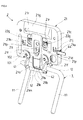
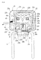
- FIG. 4 is a perspective view of a headrest frame to which a pillar is assembled and a locking means, viewed from the side on which the headrest frame comes into contact with the passenger's head
- FIG. 1 is a perspective view of a seat provided with a seat back and a headrest
- FIG. 2 is a sectional view taken along the line A-A of FIG. 1
- FIG. 3 is an exploded perspective view of a headrest frame and a locking means
- FIG. 4 is a perspective view of a headrest frame to which a pillar is assembled and a locking means, viewed from the side on which the headrest frame comes into contact with the passenger's head
- FIG. 1 is a perspective view of a seat provided with a
- FIG. 5 is a front view of FIG. 4
- FIG. 6 is a rear view of FIG. 4
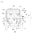
- FIG. 7 is an explanatory view of the locking means
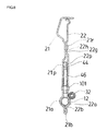
- FIG. 8 is a sectional view taken along the line B-B of FIG. 5
- FIG. 9 is a perspective view of the pillar
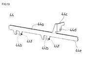
- FIG. 10 is a perspective view of a ratchet lever
- FIG. 11 is a plan view of a ratchet
- FIG. 12 is a side view of a latch plate
- FIG. 13 is a schematic sectional view showing a transverse cross section of the headrest
- FIG. 14 is a partially expanded view of FIG. 13
- FIG. 15 is a partially exploded perspective view of a cover.
- a vehicle seat S of this embodiment is an example of a rear seat of an automobile seat.
- the vehicle seat S includes a seat cushion S1 and a seat back S2, and in the upper part of the seat back S2, a headrest HR is provided.
- the seat cushion S1 and the seat back S2 have a publicly known configuration in which a frame, a pad, and a seat cover material for covering the frame and pad are provided, and therefore the details thereof are omitted.
- explanation is given by taking the rear seat of the automobile seat as an example.
- the present invention can be applied to a front seat or an intermediate seat of vehicle as far as the seat can be mounted with the headrest.
- the headrest HR of this embodiment can be mounted on the seat back S2 via a pillar 1 serving as a supporting member so that the height thereof can be adjusted.
- a publicly known height adjusting mechanism can be used, and therefore the details of the mechanism are omitted.
- the headrest HR of this embodiment can be made in a head support state in which the headrest HR is raised with respect to the seat back S2 and in a storage state tilted from the head support state (in the example shown in FIG. 1 , the left-hand side in the figure shows the storage state).
- the headrest HR of this embodiment includes, as principal components, the pillar 1 serving as the supporting member, a headrest frame 2 serving as a frame, headrest frame urging means 3 serving as frame urging means, and locking means 4.
- the pillar 1 serving as the supporting member of this embodiment has two leg parts 11, 11 mounted on the upper part of the seat back S2, and a transverse shaft part 12 for connecting the two leg parts 11, 11 to each other.
- latch plates 41 and 42 serving as locking members are fixed perpendicularly to the axis of the transverse shaft part 12 at a predetermined interval by welding or the like.
- a portion between the latch plates 41 and 42 of the transverse shaft part 12 is rotatably held by substantially semicircular lower assembling concave parts 21a and 22a formed in the lower part of the headrest frame 2 (a main frame 21 and a sub frame 22) serving as the frame, described below.
- the latch plates 41 and 42 of this embodiment constitute the locking means 4, described below.
- the headrest frame 2 serving as the frame of this embodiment is rotatably engaged with the transverse shaft part 12 of the pillar 1 as described above, and as shown in FIGS. 3 and 6 , is configured by being combined by a plurality of hemming staking parts 21r, 21r and blanked drawn parts 22g each having a hole 22h and hemming staking parts 21b and 22b, described below, so that the sub frame 22 enters the main frame 21.
- a ratchet lever 44 serving as an operation lever and ratchets 46 serving as fixing members are held.
- the main frame 21 and the sub frame 22 are assembled integrally to each other by staking from both front and rear sides with rivets 101 and 102 being held between them.
- the central parts 101a and 102a of the rivets 101 and 102 have a large diameter, and on both sides of the central parts 101a and 102a, staking parts 101b and 102b are formed.
- the ratchet lever 44 and the ratchets 46 of this embodiment constitute the locking means 4, described below.
- the main frame 21 of this embodiment comprises a rectangular plate body.
- the substantially semicircular lower assembling concave part 21a is formed, and the hemming staking part 21b is formed so as to be continuous with the lower assembling concave part 21a.
- the lower assembling concave part 21a is formed with a cut-away part 21m formed by cutting the middle part, and a looseness preventing piece 21k is formed so as to be directed to the cut-away part 21m. On both sides of the looseness preventing piece 21k, slits 21s are formed.
- This looseness preventing piece 21k has a spring effect due to the slits 21s, and is in contact with the transverse shaft part 12 of the pillar 1 so as to be pressed against the transverse shaft part 12. By this, the looseness between headrest frame 2 and the pillar 1 can be prevented with more certainty.
- a jutting-out 21g is formed on the upper side of the main frame 21. This jutting-out 21g is in contact with a projecting portion of a resin-made front cover member 7a, described below, and also secures the strength. Also, at the outer periphery of the main frame 21, a bent wall part 21c is formed excluding predetermined ranges on both sides of the lower assembling concave part 21a.
- boss parts 21e are formed in portions, through which the rivets 101 serving as the rotation shafts for the ratchets 46 are inserted, so as to project toward the inside. Also, on the outer periphery side of the boss part 21e, a substantially arc-shaped protruding part 21f is formed so as to project toward the rotating surface of the ratchet 46. This substantially arc-shaped protruding part 21f, together with a substantially arc-shaped protruding part 22f formed on the sub frame, described below, guides the ratchet 46 so that the ratchet 46 can be turned without play by being held between the protruding parts 21f and 22f.
- a cut-away part 21d is formed on one side face of the bent wall part 21c.
- the ratchet lever 44 is inserted through this cut-away part 21d.
- three tongue pieces 21h, 21i and 21j that are bent toward the inside are formed so as to serve as guides at the time when the ratchet lever 44 is inserted through.
- the two tongue pieces 21h and 21j of the three tongue pieces 21h, 21i and 21j are bent toward the inside from the upside to the downside, and are formed at an interval in the right and left direction. In a substantially central portion of the tongue pieces 21h and 21j arranged in the right and left direction, one tongue piece 21i that is bent toward the inside from the downside to the upside is formed.
- the ratchet lever 44 is inserted through by using the three tongue pieces 21h, 21i and 21j as the guides.
- the ratchet lever 44 of this embodiment constitutes the locking means 4, described below.
- embossed parts 21p, 21p directed to the ratchet lever 44 side are formed.
- the sub frame 22 of this embodiment comprises a rectangular plate body, and is configured so that the upper part of a predetermined position, that is, the arrangement position of the above-described ratchet lever 44 in this embodiment, is offset to one side (toward the direction distant from the cut-away part 21d).
- a bent part 22c is formed in the upper part and at the right and left excluding the lower side.
- the inside of the bent part 22c is formed as an expanding part 22d expanding from the normal surface.
- This expanding part 22d together with an urge receiving part 22k, described below, makes the normal surface (on the front side of paper of FIG. 6 ) low.
- the configuration is made such that the rivets 101 and 102 and the hemming staking parts 21r, 21r are at positions lower than the expanding part 22d and the urge receiving part 22k, so that interference with other members can be prevented.
- FIG. 7 at positions separating through a predetermined distance from the centerline of the sub frame 22, the blanked drawn parts 22g that project to the opposed main frame 21 side and have the hole 22h for hemming staking are formed.
- the substantially semicircular lower assembling concave part 22a is formed, and the hemming staking part 22b is formed so as to be continuous with the lower assembling concave part 22a.
- the main frame 21 and the sub frame 22 are staked in the same direction from the main frame 21 side to the sub frame 22 side by the hemming staking parts 21r, 21r and the blanked drawn parts 22g each having the hole 22h and the hemming staking parts 21b and 22b. Therefore, the working is easy as compared with the case of burring.
- the main frame 21 side is configured so that the staking claw and the like are not exposed, and the headrest frame side on the side of coming into contact with the passenger's head is configured so that protrusions and the like are absent as far as possible.
- the urge receiving part 22k is formed by drawing so as to be continuous with the lower assembling concave part 22a. As shown in FIG. 6 , this urge receiving part 22k is configured so as to be in contact with the other end 33b of a spring 33, and is formed so as to be raised on the spring arrangement side. Also, the urge receiving part 22k is in contact with the spring 33 constituting the headrest frame urging means 3 and also comes into contact with a damper 32, described below, at the rotating time, thereby preventing looseness and noise.
- the bent part 22c (refer to FIG. 7 ) that is bent to the inside is formed in the upper part and at the right and left excluding the side on which the substantially semicircular lower assembling concave part 22a is provided.
- boss parts 22e projecting toward the inside are formed at positions matching the boss parts 21e of the main frame 21, that is, in portions through which the rivets 101 serving as the rotation shafts for the ratchets 46 are inserted.
- the embossed parts 22p, 22p directed to the ratchet lever 44 side are formed.
- the substantially arc-shaped protruding parts 22f projecting toward the rotating surface of the ratchet 46 are formed so as to match the substantially arc-shaped protruding parts 21f formed on the main frame 21.
- the headrest frame urging means 3 serving as the frame urging means are configured so as to urge the headrest frame 2 to one side (that is, the tilt side), and includes a shaft 31, the damper 32, the spring 33, shaft insertion holes 41d and 42d formed in the latch plates 41 and 42 constituting the locking means 4, and the above-described urge receiving part 22k.
- the shaft 31 is a round bar, and the damper 32 is formed by a hollow cylindrical body made of rubber. Also, the spring 33 is disposed so that one end 33a thereof is locked to the latch plate 41, and the other end 33b side is in contact with the damper 32. Also, the other end 33b is made a wide pressing part, and is brought into contact with the above-described urge receiving part 22k. By urging, at the normal time, the headrest frame 2 is subject to an urging force toward the tilt direction.
- the shaft 31 is inserted between the two latch plates 41 and 42.
- the shaft 31 is inserted through the shaft insertion hole 41d (or 42d) in one latch plate 41 (or 42), and then the damper 32 and the spring 33 are placed on the shaft 31.
- the shaft 31 is inserted through the shaft insertion hole 42d (or 41d) in the other latch plate 42 (or 41).
- Symbol 4 shown in FIG. 7 denotes the locking means, which are provided between the pillar 1 and the headrest frame 2.
- the locking means 4 of this embodiment include, as principal components, the latch plates 41 and 42 serving as the locking members, the ratchet lever 44 serving as the operation lever, the ratchets 46 serving as the fixing members, and a spring 45 serving as a ratchet lever urging means (operation lever urging means).
- the latch plates 41 and 42 of this embodiment are fixed to the transverse shaft part 12 of the pillar 1 perpendicularly to the axis of the transverse shaft part 12 at a predetermined interval by welding or the like. As shown in FIG. 9 , in the upper parts of the latch plates 41 and 42, engagement groove parts 41a and 42a are formed along the transverse shaft part 12.
- latch plates 41 and 42 arcuate outer peripheral parts 41b and 42b and stopper parts 41c and 42c configured by walls of portions of the engagement groove parts 41a and 42a are formed.
- the latch plates 41 and 42 are formed so that the engagement groove parts 41a and 42a have a different shape.
- the engagement groove part 42a of the latch plate 42 provided on the right-hand side in FIG. 9 is formed so that the upper end side thereof is narrower, and the engagement groove part 41a of the latch plate 41 provided on the left-hand side in FIG. 9 is formed into a shape such that the groove width is unchanged in the up and down direction.
- stopper parts 41e and 42e are formed on the end part side (the lower side in FIG. 9 ) on the side on which the headrest frame 2 of the latch plates 41 and 42 tilts.
- FIG. 12 is a side view of the latch plate 42.
- the upper side of the engagement groove part 42a of the latch plate 42 tilts to the inside with a portion that is slightly wider than the thickness of the ratchet 46 being left (angle ⁇ in FIG. 12 ).
- the engagement groove part 42a of at least one latch plate (in this embodiment, the latch plate 42) is formed so that the upper end side is narrower. Therefore, the contact points between the latch plate 42 and the ratchet 46 in an raised state are an upper end part 42f of the engagement groove part 42a of the latch plate 42 and a lock engagement point 46c of the ratchet 46 shown in FIG. 11 .
- the lock engagement point 46c which is the contact point, is at a side position at the time when the ratchet 46 comes into contact with a groove bottom 42g of the engagement groove part 42a of the latch plate 42.
- Symbol 46d shown in FIG. 11 denotes a locus along which the ratchet 46 is moved from a disengagement position deviating from the engagement groove part 42a to a position at which the ratchet 46 comes into contact with the groove bottom 42g of the engagement groove part 42a of the latch plate 42.
- the configuration is made such that the portion that comes into contact with the ratchet 46 on the upper end side formed so as to be narrow of the latch plate 42 has a larger distance Z from the transverse shaft part 12 of the pillar 1 than other parts located in the engagement groove part 42a of the ratchet 46. Therefore, the contact point separates from the axis (the rotation center of the headrest frame 2) of the transverse shaft part 12 of the pillar 1, and when the ratchet 46 moves from the engagement position to the disengagement position (when the locking is released), the release load due to the urging force of the headrest frame urging means 3 (the spring 33) from the rear can be reduced, which enables the adjustment of release load.
- the engagement groove part 42a of the latch plate 42 located on the side engaging with an operation knob of the ratchet lever 44 is formed so as to have a narrow width, so that the transmission of a force from the ratchet lever 44 can be accomplished with certainty.
- the latch plates 41 and 42 are provided with the shaft insertion holes 41d and 42d for inserting the shaft 31, respectively.
- the ratchet lever 44 of this embodiment is formed by a slender plate body.
- a main plate body 44a slides in the transverse direction, and the main plate body 44a is formed with engagement concave parts 44b, 44b directed to the pillar 1 side.
- a movement locking part 44c is formed substantially at right angles to the main plate body 44a, and the movement locking part 44c is formed with a locking part 44d of the ratchet lever urging means 45.
- Each of the engagement concave parts 44b, 44b is formed between jutting-out parts 44f, 44f projecting from the main plate body 44a to the pillar 1 side, and is formed so as to hold one circular end side of the ratchet 46 and to allow the ratchet 46 to rotate.
- one end of the ratchet lever urging means (the spring 45) is connected so that the ratchets 46 are urged in the direction of the engagement groove parts 41a and 42a of the latch plates 41 and 42.
- Symbol 44e denotes the end part side engaged with the operation knob.
- a locking part 44d on one end side of the spring 45 is formed, and in the bent wall part 21c of the main frame 21 located on the lower side ( FIG. 6 ) of the locking part 44d of the spring 45, a locking part 21u on the other side of the spring 45 is formed (refer to FIG. 4 ).
- the spring 45 urges the movement locking part 44c of the ratchet lever 44 slantwise downward.
- the main frame 21 is formed with the tongue pieces 21h and 21i.
- the ratchet lever 44 is urged as indicated by the arrow mark in FIG. 6
- the other end side of the ratchet lever 44 is urged to the tongue piece 21h side with the tongue piece 21i being a support point. Therefore, the operation knob 47 side of the ratchet lever 44 comes closest to or into contact with the garnish 7d, and the other side thereof comes into contact with the tongue piece 21h, whereby the movement in the up and down direction is regulated.
- vibrations occur for example, when the vehicle is running, abnormal sounds and noise caused by the movement of the ratchet lever 44 can be prevented.
- FIG. 15 shows an assembled state of a cover material 7.
- the cover material 7 includes the resin-made front cover member 7a and rear cover member 7b, a seat cover fastening cover member 7c, and a garnish 7d for preventing the operation knob and the like of the control section from coming off.
- a pad material 8 is disposed at the outer periphery of the cover material 7, and a seat cover material 9 covers the pad material 8.
- FIG. 13 is a schematic sectional view showing the transverse cross section of the headrest
- FIG. 14 is a partially expanded view of FIG. 13 .
- the cover material 7 comprising the resin-made front cover member 7a and rear cover member 7b.
- the cover material 7 is formed with a hollow cylindrical flange part 7f so that the cylindrical flange part 7f surrounds the end part of the ratchet lever 44.
- the garnish 7d is disposed.
- the terminal treatment is accomplished by holding the end part of the seat cover material 9 between the cylindrical flange part 7f and the garnish 7d.
- the end part 44e of the ratchet lever 44 extends from a space formed by the cylindrical flange part 7f and the garnish 7d, and the operation knob 47 is attached to the end part 44e. Since the movement locking part 44c of the ratchet lever 44 is urged slantwise downward by the above-described spring 45, the operation knob 47 comes closet to or into contact with the garnish 7d, so that regulation is accomplished.
- the ratchet 46 of this embodiment includes a rotation hole 46a serving as a rotation axis, an engagement part 46b, and the lock engagement point 46c, and is pivotally supported on the headrest frame 2 with the rivet 101 arranged between the main frame 21 and the sub frame 22 being used as a rotation shaft.
- the substantially arc-shaped protruding parts 21f and the substantially arc-shaped protruding parts 22f are formed so as to project toward the rotating surface of the ratchet 46 to guide the rotating of the ratchets 46.
- the engagement part 46b on one end side of the ratchet 46 engages with the engagement concave part 44b, 44b of the ratchet lever 44, and the lock engagement point 46c on the other end side engages with the engagement groove part 41a, 42a of the latch plate 41, 42, whereby the raised state of the headrest HR is kept.
- the engagement part 46b on one end side of the ratchet 46 engages with the engagement concave part 44b, 44b of the ratchet lever 44, and the surface tangent to the engagement concave part 44b, 44b is formed into a circular shape, preferably into a complete round shape. Thereby, the ratchet 46 can be rotated stably following the movement of the ratchet lever 44.
- the ratchet 46 has a thickness larger than that of the ratchet lever 44. Therefore, the ratchet 46 can be prevented from coming off the ratchet lever 44.
- the distance X1 between the center of the rotation hole 46a of the ratchet 46 and the center of the engagement part 46b on one end side of the ratchet 46 engaging with the engagement concave part 44b of the ratchet lever 44 is set so as to be longer than the distance Y1 between the center of the rotation hole 46a of the ratchet 46 and the position of the lock engagement point 46c (in FIG. 11 , the locus 46d) on the other end side of the ratchet 46 crossingly engaging with the engagement groove part 42a of the latch plate 42.
- the ratchet 46 pivotally supported on the headrest frame 2 is urged toward the tilt direction by the spring 33, so that friction occurs in a portion in which the ratchet 46 is in contact with the engagement groove part 42a of the latch plate 42. Therefore, when the ratchet 46 is rotated from the engagement position at which the ratchet 46 is positioned in the engagement groove part 42a of the latch plate 42 to the disengagement position at which the ratchet 46 deviates from the engagement groove part 42a, frictional resistance arises, so that a state in which the ratchet 46 is difficult to rotate is formed.
- the ratchet 46 of this embodiment is formed so that the distance X1 between the center (support point) of the rotation hole 46a and the center (power point) of the engagement part 46b to which a load is applied by the ratchet lever 44 is longer than the distance Y1 between the center (support point) of the rotation hole 46a and the position (point of application) of the lock engagement point 46c crossingly engaging with the engagement groove part 42a of the latch plate 42. Therefore, the ratchet 46 can be moved from the engagement position to the disengagement position with a small force. That is to say, a so-called link ratio can be set, and thereby the release load can be adjusted.
- the ratchet lever 44 is configured so as to hold one circular end side of the ratchet 46 and to allow the ratchet 46 to rotate, the engagement part 46b on one end side of the ratchet 46 is held in the engagement concave part 44b of the ratchet lever 44, and always engages with the ratchet lever 44, so that the turning of only one ratchet 46 can be prevented. That is to say, the ratchets 46 smoothly turn always following the movement of the ratchet lever 44, malfunction is prevented, and a changeover due to the locking means 4 can be accomplished with certainty.
- the ratchet 46 of this embodiment can rotate in a rotation angle range of 20 to 40 degrees around the rotation hole (rotation axis) 46a.
- the ratchet 46 is configured so as to rotate in a rotation angle range of 20 to 40 degrees around the rotation hole (rotation axis) 46a, disengagement of the ratchet 46 from the latch plate 41, 42 due to the rotation from the engagement position to the disengagement position and the transverse displacement of the ratchet lever 44 for the rotation of the ratchet 46 can be adjusted so as to be optimum.
- the displacement relating to the operation can be adjusted by the locking means 4.
- the seat cover material 9 of this embodiment is formed into a bag shape one end side of which is open.
- the front cover member 7a and the rear cover member 7b in which the headrest frame 2 and other various members are fitted are inserted through the opening part, and the seat cover terminal part on the opening side of the seat cover material 9 is covered by the seat cover fastening cover member 7c.
- An assembly of the seat cover material 9 and the cover material 7 is arranged in the cavity of a mold, and foaming is performed by injecting a foaming resin into a space between the seat cover material 9 and the cover material 7, whereby the pad material 8 is molded integrally with the seat cover material 9 and the cover material 7.
- the headrest HR configured as described above is explained. Since the headrest frame 2 of the headrest HR is rotatably mounted to the transverse shaft part 12 of the pillar 1, and is fixed by the locking means 4, the headrest HR at the normal time can protect the head of a seated person when a shock is applied in an raised state.
- the pillar 1 mounted on the upper part of the seat back S2 has the transverse shaft part 12, and the transverse shaft part 12 of the pillar 1 and the headrest frame 2 are rotatably engaged with each other.
- the headrest frame 2 is urged so as to be tilted by the headrest frame urging means 3.
- the tilt is made in a locked state by the locking means 4 provided between the headrest frame 2 and the pillar 1.
- This raised state is shown in FIGS. 4 to 7 . Therefore, the headrest HR is in the raised state as shown in FIG. 2 .
- the ratchet 46 rotates around the rotation axis, and the lock engagement point 46c on the other end side of the ratchet 46 moves in the direction crossing the engagement groove part 41a, 42a of the latch plate 41, 42.
- the ratchet 46 is located in the engagement groove part 41a, 42a and is in contact with the latch plate 41, 42. Therefore, the pillar 1 and the headrest frame 2 are in a locked state, and the raised state of the headrest HR is kept.
- the engagement part 46b on one end side of the ratchet 46 is pushed, and the ratchet 46 is rotated around the rotation axis. Therefore, the ratchet 46 retracts from the engagement groove part 41a, 42a, and the ratchet 46 comes off the engagement groove part 41a, 42a of the latch plate 41, 42.
- the spring 33 which is the headrest frame urging means 3, urges the headrest frame 2 toward the tilt direction, so that the headrest HR tilts around the transverse shaft part 12, becoming in a storage state.
- the ratchet lever 44, the latch plates 41 and 42, and the ratchets 46 are used as the locking means 4, and the changeover between the engagement position and the disengagement position is accomplished via the ratchet 46 one end side of which engages with the engagement concave part 44b of the ratchet lever 44 and the other end side of which can crossingly engage with the engagement groove part 41a, 42a of the latch plate 41, 42. Therefore, the locking means 4 themselves can be configured so as to be compact without requiring a great width.
- the engagement groove parts 41a and 42a of the latch plates 41 and 42 serving as the locking members is formed so that the upper end side thereof is narrower, the contact point between the latch plate 42 and the ratchet 46 separates from the transverse shaft part 12 of the pillar 1. Therefore, the release load due to the urging force of the headrest frame urging means 3 (the spring 33) from the rear at the time when the locking is released can be reduced.
- the ratchet lever 44 is urged in the direction in which the ratchet 46 is engaged with the engagement groove part 41a, 42a of the latch plate 41, 42.
- the ratchet lever 44 is urged in the direction in which the ratchet 46 is engaged with the engagement groove part 41a, 42a of the latch plate 41, 42.
- the ratchet lever 44 is disconnected from the engagement groove part 41a, 42a, and by the headrest frame urging means 3, the headrest frame 2 is tilted to the storage state, so that the headrest HR tilts. Therefore, the locking of the locking means 4 can be released by one operation (one action).
- the ratchet 46 is turned smoothly in the engagement concave part 44b of the ratchet lever 44 with the movement of the ratchet lever 44. Therefore, the ratchet 46 can be engaged with and disengaged from the engagement groove part 41a, 42a of the latch plate 41, 42, so that an exact locking releasing operation can be performed.
- two latch plates 41 and 42 serving as the locking members of the locking means 4, and two ratchets 46 serving as the fixing member are provided.
- the number of these elements may be one or three or more. It is a matter of course that according to the number, one or a plurality of engagement concave parts 44b of the ratchet lever 44 serving as the operation lever can be formed.
Landscapes
- Engineering & Computer Science (AREA)
- Aviation & Aerospace Engineering (AREA)
- Transportation (AREA)
- Mechanical Engineering (AREA)
- Seats For Vehicles (AREA)
- Chair Legs, Seat Parts, And Backrests (AREA)
Abstract
Description
- The present invention relates to a headrest and a vehicle seat provided with the headrest. More particularly, it relates to a headrest capable of being made in a head support state in which the headrest is raised with respect to a seat back and in a storage state tilted from the head support state, and a vehicle seat provided with the headrest.
- Generally, a headrest for protecting the passenger's head is mounted on the upper part of a seat back of a vehicle seat. Conventionally, there has been publicly known a configuration in which the lower part of a pillar of the headrest is attached to a transverse rod, which extends in the right and left direction in the seat back, so as to be rotatable in the front and rear direction, and the pillar is attached so as to be movable in the right and left direction, whereby the headrest is moved transversely and then is tilted to the rear to be stored (refer to Patent Document 1).
Also, there has been proposed a technique in which a headrest includes a pillar that has a transverse shaft part and is mounted on the upper part of a seat back; a headrest main body the lower side of which is rotatably provided in the transverse shaft part of the pillar; and a tilting mechanism incorporated in the headrest main body to tilt the headrest main body to the rear, and the tilting mechanism includes a headrest urging means for urging the upper part of the headrest main body to the rear side; a lock plate that is provided in the transverse shaft part of the pillar and has a first locking part; a latch that is provided in the headrest main body and has a second locking part capable of being locked to the first locking part of the lock plate; a latch urging means for urging the latch so as to lock the second locking part to the first locking part of the lock plate; and an actuator for disengaging the second locking part of the latch from the first locking part of the lock plate against the urging force of the latch urging means (refer to Patent Document 2).
Furthermore, there has been proposed a technique in which in a tilting headrest in which a bracket can be moved to a folded position and to an erected position, a concave part is formed in a locking reciprocating member and a locking member, and the locking reciprocating member is made slidable to a locked position and to an unlocked position by a spring (refer to Patent Document 3). -
- Patent Document 1: Japanese Unexamined Utility Model Application Publication No.
7-11951 - Patent Document 2: Japanese Unexamined Patent Application Publication No.
2005-349915 - Patent Document 3:
WO2005/120894A1 - The publicly known example of
Patent Document 1 has a problem in that the headrest rotates to the rear greatly together with the pillar and therefore the displacement thereof is large, and also the headrest occupies a large space when being stored because the rotating support point of the headrest exists in the upper part of the seat back under the headrest.
That is to say, when the headrest is tilted to the rear, the whole of the headrest projects to the rear side. This example also has a problem in that a pillar movement groove must be formed in the upper part of the seat back, so that not only is the construction complicated but also the headrest cannot be used commonly for other seat backs. - The publicly known technique of
Patent Document 2 has high versatility because the tilting mechanism of the headrest can be accommodated entirely in the headrest main body. However, this technique has a problem in that a size of some degree must be secured in the front and rear direction, and the thinning of headrest is limited because the first locking part of the lock plate and the second locking part provided on the latch to be locked to the first locking part are used, and the lock plate and the latch are arranged in the tilt direction. - In the publicly known technique of
Patent Document 3, the concave part is formed in the locking reciprocating member and the locking member, and the locking reciprocating member is made slidable to a locked position and to an unlocked position by the spring. Since the locked position and the unlocked position are changed over by the two members of the locking reciprocating member and the locking member, a spring force for urging a bracket in the fold direction is applied directly to the locking reciprocating member and the locking member, so that in some cases, it is difficult for the reciprocating movement of the locking reciprocating member to be accomplished smoothly. Also, in the case where a plurality of locking members are present, one locking reciprocating member is made slidable to the locked position and the unlocked position with respect to all the locking members. Therefore, this technique has a disadvantage in that the locking reciprocating member becomes large, so that a higher load is applied to the locking reciprocating member.
Also, in any of the above-described publicly known techniques, in a condition where vibrations occur, for example, when the vehicle is running, consideration has not been given to abnormal sounds and noise caused by the headrest. - An object of the present invention is to provide a headrest that has high versatility, is thin in shape, and is capable of being operated smoothly by reducing an operation load at the time when the headrest is tilted from a head support state to a storage state, and a vehicle seat provided with the headrest.
Another object of the present invention is to provide a headrest capable of preventing abnormal sounds and noise caused by a headrest in a condition where vibrations occur, for example, when the vehicle is running, and a vehicle seat provided with the headrest. - To achieve the above object, the present invention provides a headrest capable of being made in a head support state in which the headrest is raised with respect to a seat back and in a storage state tilted from the head support state, including a supporting member mounted on the upper part of the seat back; a headrest frame rotatably engaged with the supporting member; a frame urging means for urging the headrest frame to one side; a locking means capable of hindering the rotating of the headrest frame and the supporting member; and an operation lever for operating the locking means, characterized in that the operation lever having a concave part formed toward the supporting member side is formed so as to be movable in the direction different from the rotating direction of the headrest frame, and is urged in the predetermined direction by an operation lever urging means.
- At this time, it is preferable that the operation lever urging means urge the operation lever in the direction at a predetermined angle to the movement direction of the operation lever.
- To solve the above object, the present invention provides a headrest capable of being made in a head support state in which the headrest is raised with respect to a seat back and in a storage state tilted from the head support state, including a pillar having a transverse shaft part and mounted to the upper part of the seat back; a headrest frame rotatably engaged with the transverse shaft part of the pillar; a headrest urging means for urging the headrest frame to one side; a locking means capable of hindering the rotating of the headrest frame and the pillar; a ratchet lever that operates the locking means and slides in the transverse direction; and a ratchet lever urging means for urging the ratchet lever, characterized in that the ratchet lever urging means urges the ratchet lever in the direction at a predetermined angle to the ratchet lever sliding in the transverse direction.
- By the above-described configuration, a force in the fixed direction is applied to the operation lever (ratchet lever), and the movement in the direction different from the movement direction of the operation lever (ratchet lever) is regulated by this force in the fixed direction, so that looseness can be prevented, and the occurrence of abnormal sounds (noise) can be prevented.
- In the above-described configuration, it is preferable that a cover material be disposed on the outer periphery side of the headrest frame; at the arrangement position of the ratchet lever of the cover material, a hole be formed so that the end part of the ratchet lever is extendable; a garnish be disposed in the hole; in the end part of the ratchet lever extending from the garnish, an operation knob be disposed; and the operation knob be configured so as to come closest to the garnish in the urging direction of the ratchet lever urging means.
- If the operation knob is configured so as to come closest to the garnish in the urging direction of the urging means as described above, the distance between the operation knob and the garnish becomes shortest, or the operation knob comes into contact with the garnish, so that looseness caused by swaying and the like during running can be prevented.
- Also, in the above-described configuration, it is preferable that the headrest frame be formed with at least a tongue piece, which is bent to the inside toward the ratchet lever, on the opposite side to the arrangement position of the ratchet lever urging means so as to hold the ratchet lever, and the tongue piece serve as a guide for the ratchet lever.
- By the above-described configuration, on the side of disposition position of the ratchet lever urging means, the distance between the operation knob and the garnish is made shortest, or the operation knob is brought into contact with the garnish, and on the other side, the position is fixed by a portion in which the ratchet lever comes into contact with the tongue piece and is guided. Therefore, looseness of the ratchet lever caused by swaying and the like during running can be prevented, and the occurrence of abnormal sounds and noise can be prevented.
- To achieve the above object, the present invention provides a vehicle seat provided with the headrest having the above-described configuration.
- According to the present invention, there can be provided a headrest that has high versatility, is thin in shape, and is capable of being operated smoothly by reducing an operation load at the time when the headrest is tilted from a head support state to a storage state, and a vehicle seat provided with the headrest.
Also, in a condition where vibrations occur, for example, when the vehicle is running, abnormal sounds and noise caused by the headrest can be prevented. -
-
FIG. 1 is a perspective view of a seat provided with a seat back and a headrest; -
FIG. 2 is a sectional view taken along the line A-A ofFIG. 1 ; -
FIG. 3 is an exploded perspective view of a headrest frame and a locking means; -
FIG. 4 is a perspective view of a headrest frame to which a pillar is assembled and a locking means, viewed from the side on which the headrest frame comes into contact with the passenger's head; -
FIG. 5 is a front view ofFIG. 4 ; -
FIG. 6 is a rear view ofFIG. 4 ; -
FIG. 7 is an explanatory view of a locking means; -
FIG. 8 is a sectional view taken along the line B-B ofFIG. 5 ; -
FIG. 9 is a perspective view of a pillar; -
FIG. 10 is a perspective view of a ratchet lever; -
FIG. 11 is a plan view of a ratchet; -
FIG. 12 is a side view of a latch plate; -
FIG. 13 is a schematic sectional view showing a transverse cross section of a headrest; -
FIG. 14 is a partially expanded view ofFIG. 13 ; and -
FIG. 15 is a partially exploded perspective view of a cover. -
- 1
- pillar
- 2
- headrest frame
- 3
- headrest frame urging means
- 4
- locking means
- 7
- cover material
- 7a
- front cover member
- 7b
- rear cover member
- 7c
- seat cover fastening cover member
- 7d
- garnish
- 7f
- cylindrical flange part
- 8
- pad material
- 9
- seat cover material
- 11
- leg part
- 12
- transverse shaft part
- 21
- main frame
- 21a
- lower assembling concave part
- 21b
- hemming staking part
- 21c
- bent wall part
- 21d
- cut-away part
- 21e
- boss part
- 21f
- protruding part
- 21g
- jutting-out part
- 21h, 21i, 21j
- tongue piece
- 21k
- looseness preventing piece
- 21m
- cut-away part
- 21p
- embossed part
- 21r
- hemming staking part
- 21s
- slit
- 21u
- locking part
- 22
- sub frame
- 22a
- lower assembling concave part
- 22b
- hemming staking part
- 22c
- bent part
- 22d
- expanding part
- 22e
- boss part
- 22f
- protruding part
- 22g
- blanked drawn part
- 22h
- hole
- 22k
- urge receiving part
- 22p
- embossed part
- 31
- shaft
- 32
- damper
- 33
- spring
- 33a
- one end
- 33b
- the other end
- 41, 42
- latch plate
- 41a, 42a
- engagement groove part
- 41b, 42b
- outer peripheral part
- 41c, 42c
- stopper part
- 41d, 42d
- shaft insertion hole
- 41e, 42e
- stopper part
- 42f
- upper end part
- 42g
- groove bottom
- 44
- ratchet lever
- 44a
- main plate body
- 44b, 44b
- engagement concave part
- 44c
- movement locking part
- 44d
- locking part
- 44e
- end part
- 44f, 44f
- jutting-out part
- 45
- ratchet lever urging means (spring)
- 46
- ratchet
- 46a
- rotation hole
- 46b
- engagement part
- 46c
- lock engagement point
- 46d
- locus
- 47 ...
- operation knob
- 101, 102
- rivet
- 101a, 102a
- central part
- 101b, 102b
- staking part
- S
- vehicle seat
- S1
- seat cushion
- S2
- seat back
- HR
- headrest
- An embodiment of the present invention will now be described with reference to the accompanying drawings. The members, arrangements, and the like explained below do not restrict the present invention, and, needless to say, can be changed variously without departing from the spirit and scope of the present invention.
The figures show one embodiment of the present invention.FIG. 1 is a perspective view of a seat provided with a seat back and a headrest,FIG. 2 is a sectional view taken along the line A-A ofFIG. 1 ,FIG. 3 is an exploded perspective view of a headrest frame and a locking means,FIG. 4 is a perspective view of a headrest frame to which a pillar is assembled and a locking means, viewed from the side on which the headrest frame comes into contact with the passenger's head,FIG. 5 is a front view ofFIG. 4 ,FIG. 6 is a rear view ofFIG. 4 ,FIG. 7 is an explanatory view of the locking means,FIG. 8 is a sectional view taken along the line B-B ofFIG. 5 ,FIG. 9 is a perspective view of the pillar,FIG. 10 is a perspective view of a ratchet lever,FIG. 11 is a plan view of a ratchet,FIG. 12 is a side view of a latch plate;FIG. 13 is a schematic sectional view showing a transverse cross section of the headrest,FIG. 14 is a partially expanded view ofFIG. 13 , andFIG. 15 is a partially exploded perspective view of a cover. - A vehicle seat S of this embodiment is an example of a rear seat of an automobile seat. As shown in
FIG. 1 , the vehicle seat S includes a seat cushion S1 and a seat back S2, and in the upper part of the seat back S2, a headrest HR is provided. The seat cushion S1 and the seat back S2 have a publicly known configuration in which a frame, a pad, and a seat cover material for covering the frame and pad are provided, and therefore the details thereof are omitted. In this embodiment, explanation is given by taking the rear seat of the automobile seat as an example. However, the present invention can be applied to a front seat or an intermediate seat of vehicle as far as the seat can be mounted with the headrest. - The headrest HR of this embodiment can be mounted on the seat back S2 via a
pillar 1 serving as a supporting member so that the height thereof can be adjusted. To adjust the height of the headrest HR, a publicly known height adjusting mechanism can be used, and therefore the details of the mechanism are omitted. - As shown in
FIG. 1 , the headrest HR of this embodiment can be made in a head support state in which the headrest HR is raised with respect to the seat back S2 and in a storage state tilted from the head support state (in the example shown inFIG. 1 , the left-hand side in the figure shows the storage state).
The headrest HR of this embodiment includes, as principal components, thepillar 1 serving as the supporting member, aheadrest frame 2 serving as a frame, headrest frame urging means 3 serving as frame urging means, and locking means 4. - As shown in
FIGS. 3 and9 , thepillar 1 serving as the supporting member of this embodiment has twoleg parts transverse shaft part 12 for connecting the twoleg parts transverse shaft part 12 of thepillar 1,latch plates transverse shaft part 12 at a predetermined interval by welding or the like. A portion between thelatch plates transverse shaft part 12 is rotatably held by substantially semicircular lower assemblingconcave parts main frame 21 and a sub frame 22) serving as the frame, described below.
Thelatch plates - The
headrest frame 2 serving as the frame of this embodiment is rotatably engaged with thetransverse shaft part 12 of thepillar 1 as described above, and as shown inFIGS. 3 and6 , is configured by being combined by a plurality of hemmingstaking parts parts 22g each having ahole 22h andhemming staking parts sub frame 22 enters themain frame 21.
In theheadrest frame 2 comprising themain frame 21 and thesub frame 22, aratchet lever 44 serving as an operation lever and ratchets 46 serving as fixing members are held. Themain frame 21 and thesub frame 22 are assembled integrally to each other by staking from both front and rear sides withrivets central parts rivets central parts parts ratchet lever 44 and theratchets 46 of this embodiment constitute the locking means 4, described below. - As shown in
FIGS. 3 and5 , themain frame 21 of this embodiment comprises a rectangular plate body. In the lower part thereof, the substantially semicircular lower assemblingconcave part 21a is formed, and thehemming staking part 21b is formed so as to be continuous with the lower assemblingconcave part 21a. The lower assemblingconcave part 21a is formed with a cut-awaypart 21m formed by cutting the middle part, and alooseness preventing piece 21k is formed so as to be directed to the cut-awaypart 21m. On both sides of thelooseness preventing piece 21k,slits 21s are formed. Thislooseness preventing piece 21k has a spring effect due to theslits 21s, and is in contact with thetransverse shaft part 12 of thepillar 1 so as to be pressed against thetransverse shaft part 12. By this, the looseness betweenheadrest frame 2 and thepillar 1 can be prevented with more certainty.
On the upper side of themain frame 21, a jutting-out 21g is formed. This jutting-out 21g is in contact with a projecting portion of a resin-madefront cover member 7a, described below, and also secures the strength.
Also, at the outer periphery of themain frame 21, abent wall part 21c is formed excluding predetermined ranges on both sides of the lower assemblingconcave part 21a. - On the inside of the
main frame 21,boss parts 21e are formed in portions, through which therivets 101 serving as the rotation shafts for theratchets 46 are inserted, so as to project toward the inside. Also, on the outer periphery side of theboss part 21e, a substantially arc-shaped protrudingpart 21f is formed so as to project toward the rotating surface of theratchet 46. This substantially arc-shaped protrudingpart 21f, together with a substantially arc-shaped protrudingpart 22f formed on the sub frame, described below, guides theratchet 46 so that theratchet 46 can be turned without play by being held between the protrudingparts - On one side face of the
bent wall part 21c, a cut-awaypart 21d is formed. Theratchet lever 44 is inserted through this cut-awaypart 21d. Also, on the extension of the cut-awaypart 21d, threetongue pieces ratchet lever 44 is inserted through. - The two
tongue pieces tongue pieces tongue pieces tongue piece 21i that is bent toward the inside from the downside to the upside is formed. Theratchet lever 44 is inserted through by using the threetongue pieces ratchet lever 44 of this embodiment constitutes the locking means 4, described below. - Furthermore, in the state in which the
ratchet lever 44 is inserted through, at the position of theratchet lever 44 of themain frame 21, embossedparts ratchet lever 44 side are formed. The embossedparts 21p, together withembossed parts 22p formed on thesub frame 22, described below, guide theratchet lever 44 so that theratchet lever 44 can be moved without a play by being held between theembossed parts - As shown in
FIGS. 3 ,6 and7 , thesub frame 22 of this embodiment comprises a rectangular plate body, and is configured so that the upper part of a predetermined position, that is, the arrangement position of the above-describedratchet lever 44 in this embodiment, is offset to one side (toward the direction distant from the cut-awaypart 21d). - Also, as shown in
FIGS. 6 and7 , abent part 22c is formed in the upper part and at the right and left excluding the lower side. The inside of thebent part 22c is formed as an expandingpart 22d expanding from the normal surface. This expandingpart 22d, together with an urge receiving part 22k, described below, makes the normal surface (on the front side of paper ofFIG. 6 ) low. By this, the configuration is made such that therivets hemming staking parts part 22d and the urge receiving part 22k, so that interference with other members can be prevented.
As shown inFIG. 7 , at positions separating through a predetermined distance from the centerline of thesub frame 22, the blanked drawnparts 22g that project to the opposedmain frame 21 side and have thehole 22h for hemming staking are formed. - In the lower part of the
sub frame 22, the substantially semicircular lower assemblingconcave part 22a is formed, and thehemming staking part 22b is formed so as to be continuous with the lower assemblingconcave part 22a.
As described above, themain frame 21 and thesub frame 22 are staked in the same direction from themain frame 21 side to thesub frame 22 side by thehemming staking parts parts 22g each having thehole 22h and thehemming staking parts main frame 21 side is configured so that the staking claw and the like are not exposed, and the headrest frame side on the side of coming into contact with the passenger's head is configured so that protrusions and the like are absent as far as possible. - Also, on the opposite side to the
hemming staking part 22b, the urge receiving part 22k is formed by drawing so as to be continuous with the lower assemblingconcave part 22a. As shown inFIG. 6 , this urge receiving part 22k is configured so as to be in contact with theother end 33b of aspring 33, and is formed so as to be raised on the spring arrangement side. Also, the urge receiving part 22k is in contact with thespring 33 constituting the headrest frame urging means 3 and also comes into contact with adamper 32, described below, at the rotating time, thereby preventing looseness and noise.
Thebent part 22c (refer toFIG. 7 ) that is bent to the inside is formed in the upper part and at the right and left excluding the side on which the substantially semicircular lower assemblingconcave part 22a is provided. - On the
sub frame 22,boss parts 22e projecting toward the inside are formed at positions matching theboss parts 21e of themain frame 21, that is, in portions through which therivets 101 serving as the rotation shafts for theratchets 46 are inserted. At positions of theratchet lever 44 of thesub frame 22, the embossedparts ratchet lever 44 side are formed.
Also, on the inside of thesub frame 22, the substantially arc-shaped protrudingparts 22f projecting toward the rotating surface of theratchet 46 are formed so as to match the substantially arc-shaped protrudingparts 21f formed on themain frame 21. - As shown in
FIGS. 3 and6 , the headrest frame urging means 3 serving as the frame urging means are configured so as to urge theheadrest frame 2 to one side (that is, the tilt side), and includes ashaft 31, thedamper 32, thespring 33,shaft insertion holes latch plates - The
shaft 31 is a round bar, and thedamper 32 is formed by a hollow cylindrical body made of rubber. Also, thespring 33 is disposed so that oneend 33a thereof is locked to thelatch plate 41, and theother end 33b side is in contact with thedamper 32. Also, theother end 33b is made a wide pressing part, and is brought into contact with the above-described urge receiving part 22k. By urging, at the normal time, theheadrest frame 2 is subject to an urging force toward the tilt direction. - In assembling, the
shaft 31 is inserted between the twolatch plates shaft 31 is inserted through theshaft insertion hole 41d (or 42d) in one latch plate 41 (or 42), and then thedamper 32 and thespring 33 are placed on theshaft 31. Next, theshaft 31 is inserted through theshaft insertion hole 42d (or 41d) in the other latch plate 42 (or 41). - Symbol 4 shown in
FIG. 7 denotes the locking means, which are provided between thepillar 1 and theheadrest frame 2.
The locking means 4 of this embodiment include, as principal components, thelatch plates ratchet lever 44 serving as the operation lever, theratchets 46 serving as the fixing members, and aspring 45 serving as a ratchet lever urging means (operation lever urging means). - As described above, the
latch plates transverse shaft part 12 of thepillar 1 perpendicularly to the axis of thetransverse shaft part 12 at a predetermined interval by welding or the like.
As shown inFIG. 9 , in the upper parts of thelatch plates engagement groove parts transverse shaft part 12. - On the
latch plates peripheral parts 41b and 42b andstopper parts 41c and 42c configured by walls of portions of theengagement groove parts
In this embodiment, thelatch plates engagement groove parts engagement groove part 42a of thelatch plate 42 provided on the right-hand side inFIG. 9 is formed so that the upper end side thereof is narrower, and theengagement groove part 41a of thelatch plate 41 provided on the left-hand side inFIG. 9 is formed into a shape such that the groove width is unchanged in the up and down direction. On the end part side (the lower side inFIG. 9 ) on the side on which theheadrest frame 2 of thelatch plates stopper parts -
FIG. 12 is a side view of thelatch plate 42. The upper side of theengagement groove part 42a of thelatch plate 42 tilts to the inside with a portion that is slightly wider than the thickness of theratchet 46 being left (angle α inFIG. 12 ). Thus, in this embodiment, theengagement groove part 42a of at least one latch plate (in this embodiment, the latch plate 42) is formed so that the upper end side is narrower. Therefore, the contact points between thelatch plate 42 and theratchet 46 in an raised state are anupper end part 42f of theengagement groove part 42a of thelatch plate 42 and alock engagement point 46c of theratchet 46 shown inFIG. 11 . Thelock engagement point 46c, which is the contact point, is at a side position at the time when theratchet 46 comes into contact with a groove bottom 42g of theengagement groove part 42a of thelatch plate 42.
Symbol 46d shown inFIG. 11 denotes a locus along which theratchet 46 is moved from a disengagement position deviating from theengagement groove part 42a to a position at which theratchet 46 comes into contact with the groove bottom 42g of theengagement groove part 42a of thelatch plate 42. - That is to say, as shown in
FIG. 7 , the configuration is made such that the portion that comes into contact with theratchet 46 on the upper end side formed so as to be narrow of thelatch plate 42 has a larger distance Z from thetransverse shaft part 12 of thepillar 1 than other parts located in theengagement groove part 42a of theratchet 46. Therefore, the contact point separates from the axis (the rotation center of the headrest frame 2) of thetransverse shaft part 12 of thepillar 1, and when theratchet 46 moves from the engagement position to the disengagement position (when the locking is released), the release load due to the urging force of the headrest frame urging means 3 (the spring 33) from the rear can be reduced, which enables the adjustment of release load. In the case of this embodiment, theengagement groove part 42a of thelatch plate 42 located on the side engaging with an operation knob of theratchet lever 44 is formed so as to have a narrow width, so that the transmission of a force from theratchet lever 44 can be accomplished with certainty.
Also, thelatch plates shaft insertion holes shaft 31, respectively. - As shown in
FIG. 10 , theratchet lever 44 of this embodiment is formed by a slender plate body. A main plate body 44a slides in the transverse direction, and the main plate body 44a is formed with engagement concave parts 44b, 44b directed to thepillar 1 side. On the opposite side to the engagement concave parts 44b, 44b, a movement locking part 44c is formed substantially at right angles to the main plate body 44a, and the movement locking part 44c is formed with a lockingpart 44d of the ratchet lever urging means 45. - Each of the engagement concave parts 44b, 44b is formed between jutting-
out parts pillar 1 side, and is formed so as to hold one circular end side of theratchet 46 and to allow theratchet 46 to rotate.
To theratchet lever 44, one end of the ratchet lever urging means (the spring 45) is connected so that theratchets 46 are urged in the direction of theengagement groove parts latch plates Symbol 44e denotes the end part side engaged with the operation knob. - At this time, in the movement locking part 44c of the
ratchet lever 44, a lockingpart 44d on one end side of thespring 45 is formed, and in thebent wall part 21c of themain frame 21 located on the lower side (FIG. 6 ) of the lockingpart 44d of thespring 45, a locking part 21u on the other side of thespring 45 is formed (refer toFIG. 4 ). As indicated by an arrow mark inFIG. 6 , due to the difference in locking position, thespring 45 urges the movement locking part 44c of theratchet lever 44 slantwise downward. - On the other hand, the
main frame 21 is formed with thetongue pieces ratchet lever 44 is urged as indicated by the arrow mark inFIG. 6 , the other end side of theratchet lever 44 is urged to thetongue piece 21h side with thetongue piece 21i being a support point. Therefore, theoperation knob 47 side of theratchet lever 44 comes closest to or into contact with thegarnish 7d, and the other side thereof comes into contact with thetongue piece 21h, whereby the movement in the up and down direction is regulated. By doing this, in a condition where vibrations occur, for example, when the vehicle is running, abnormal sounds and noise caused by the movement of theratchet lever 44 can be prevented. -
FIG. 15 shows an assembled state of acover material 7. After thepillar 1 serving as the supporting member, theheadrest frame 2 serving as the frame, the headrest frame urging means 3 serving as the frame urging means, the locking means 4, and the like have been assembled, these elements are covered with thecover material 7. Thecover material 7 includes the resin-madefront cover member 7a andrear cover member 7b, a seat cover fastening cover member 7c, and agarnish 7d for preventing the operation knob and the like of the control section from coming off.
As shown inFIG. 2 , apad material 8 is disposed at the outer periphery of thecover material 7, and aseat cover material 9 covers thepad material 8. -
FIG. 13 is a schematic sectional view showing the transverse cross section of the headrest, andFIG. 14 is a partially expanded view ofFIG. 13 . Referring to these figures, a state in which theoperation knob 47 side comes closest to or into contact with thegarnish 7d is explained.
As shown inFIG. 13 , the headrest frame is covered with thecover material 7 comprising the resin-madefront cover member 7a andrear cover member 7b. At this time, thecover material 7 is formed with a hollowcylindrical flange part 7f so that thecylindrical flange part 7f surrounds the end part of theratchet lever 44. In thiscylindrical flange part 7f, thegarnish 7d is disposed. The terminal treatment is accomplished by holding the end part of theseat cover material 9 between thecylindrical flange part 7f and thegarnish 7d. Theend part 44e of theratchet lever 44 extends from a space formed by thecylindrical flange part 7f and thegarnish 7d, and theoperation knob 47 is attached to theend part 44e. Since the movement locking part 44c of theratchet lever 44 is urged slantwise downward by the above-describedspring 45, theoperation knob 47 comes closet to or into contact with thegarnish 7d, so that regulation is accomplished. - As shown in
FIGS. 3 ,7 and11 , theratchet 46 of this embodiment includes a rotation hole 46a serving as a rotation axis, anengagement part 46b, and thelock engagement point 46c, and is pivotally supported on theheadrest frame 2 with therivet 101 arranged between themain frame 21 and thesub frame 22 being used as a rotation shaft.
On the inside (the opposed side) of themain frame 21 and thesub frame 22, the substantially arc-shaped protrudingparts 21f and the substantially arc-shaped protrudingparts 22f are formed so as to project toward the rotating surface of theratchet 46 to guide the rotating of theratchets 46.
Theengagement part 46b on one end side of theratchet 46 engages with the engagement concave part 44b, 44b of theratchet lever 44, and thelock engagement point 46c on the other end side engages with theengagement groove part latch plate - The
engagement part 46b on one end side of theratchet 46 engages with the engagement concave part 44b, 44b of theratchet lever 44, and the surface tangent to the engagement concave part 44b, 44b is formed into a circular shape, preferably into a complete round shape. Thereby, theratchet 46 can be rotated stably following the movement of theratchet lever 44. Theratchet 46 has a thickness larger than that of theratchet lever 44. Therefore, theratchet 46 can be prevented from coming off theratchet lever 44. - Also, as shown in
FIG. 11 , the distance X1 between the center of the rotation hole 46a of theratchet 46 and the center of theengagement part 46b on one end side of theratchet 46 engaging with the engagement concave part 44b of theratchet lever 44 is set so as to be longer than the distance Y1 between the center of the rotation hole 46a of theratchet 46 and the position of thelock engagement point 46c (inFIG. 11 , thelocus 46d) on the other end side of theratchet 46 crossingly engaging with theengagement groove part 42a of thelatch plate 42. Thereby, the release load at the time when the engagement (locking) of theratchet 46 with thelatch plate - That is to say, in this embodiment, in the raised state, the
ratchet 46 pivotally supported on theheadrest frame 2 is urged toward the tilt direction by thespring 33, so that friction occurs in a portion in which theratchet 46 is in contact with theengagement groove part 42a of thelatch plate 42. Therefore, when theratchet 46 is rotated from the engagement position at which theratchet 46 is positioned in theengagement groove part 42a of thelatch plate 42 to the disengagement position at which theratchet 46 deviates from theengagement groove part 42a, frictional resistance arises, so that a state in which theratchet 46 is difficult to rotate is formed. - However, the
ratchet 46 of this embodiment is formed so that the distance X1 between the center (support point) of the rotation hole 46a and the center (power point) of theengagement part 46b to which a load is applied by theratchet lever 44 is longer than the distance Y1 between the center (support point) of the rotation hole 46a and the position (point of application) of thelock engagement point 46c crossingly engaging with theengagement groove part 42a of thelatch plate 42. Therefore, theratchet 46 can be moved from the engagement position to the disengagement position with a small force. That is to say, a so-called link ratio can be set, and thereby the release load can be adjusted. - Also, since the
ratchet lever 44 is configured so as to hold one circular end side of theratchet 46 and to allow theratchet 46 to rotate, theengagement part 46b on one end side of theratchet 46 is held in the engagement concave part 44b of theratchet lever 44, and always engages with theratchet lever 44, so that the turning of only oneratchet 46 can be prevented. That is to say, theratchets 46 smoothly turn always following the movement of theratchet lever 44, malfunction is prevented, and a changeover due to the locking means 4 can be accomplished with certainty.
Theratchet 46 of this embodiment can rotate in a rotation angle range of 20 to 40 degrees around the rotation hole (rotation axis) 46a. - If the
ratchet 46 is configured so as to rotate in a rotation angle range of 20 to 40 degrees around the rotation hole (rotation axis) 46a, disengagement of theratchet 46 from thelatch plate ratchet lever 44 for the rotation of theratchet 46 can be adjusted so as to be optimum. Thus, the displacement relating to the operation can be adjusted by the locking means 4. - The
seat cover material 9 of this embodiment is formed into a bag shape one end side of which is open. Thefront cover member 7a and therear cover member 7b in which theheadrest frame 2 and other various members are fitted are inserted through the opening part, and the seat cover terminal part on the opening side of theseat cover material 9 is covered by the seat cover fastening cover member 7c. An assembly of theseat cover material 9 and thecover material 7 is arranged in the cavity of a mold, and foaming is performed by injecting a foaming resin into a space between theseat cover material 9 and thecover material 7, whereby thepad material 8 is molded integrally with theseat cover material 9 and thecover material 7. - Next, the operation of the headrest HR configured as described above is explained.
Since theheadrest frame 2 of the headrest HR is rotatably mounted to thetransverse shaft part 12 of thepillar 1, and is fixed by the locking means 4, the headrest HR at the normal time can protect the head of a seated person when a shock is applied in an raised state. - That is to say, the
pillar 1 mounted on the upper part of the seat back S2 has thetransverse shaft part 12, and thetransverse shaft part 12 of thepillar 1 and theheadrest frame 2 are rotatably engaged with each other. At the normal time, theheadrest frame 2 is urged so as to be tilted by the headrest frame urging means 3. In the case of the raised state, the tilt is made in a locked state by the locking means 4 provided between theheadrest frame 2 and thepillar 1. This raised state is shown inFIGS. 4 to 7 . Therefore, the headrest HR is in the raised state as shown inFIG. 2 . - In the locking means 4, when the
engagement part 46b on one end side of theratchet 46 is pushed by the sliding motion of theratchet lever 44, theratchet 46 rotates around the rotation axis, and thelock engagement point 46c on the other end side of theratchet 46 moves in the direction crossing theengagement groove part latch plate
In the case of the raised state, theratchet 46 is located in theengagement groove part latch plate pillar 1 and theheadrest frame 2 are in a locked state, and the raised state of the headrest HR is kept. - By operating the
ratchet lever 44 against the ratchet lever urging means 45, theengagement part 46b on one end side of theratchet 46 is pushed, and theratchet 46 is rotated around the rotation axis. Therefore, theratchet 46 retracts from theengagement groove part ratchet 46 comes off theengagement groove part latch plate spring 33, which is the headrest frame urging means 3, urges theheadrest frame 2 toward the tilt direction, so that the headrest HR tilts around thetransverse shaft part 12, becoming in a storage state. - As described above, when the headrest HR is made in the head support state in which the headrest HR is raised with respect to the seat back S2 and in the storage state tilted from the head support state, in the present invention, the
ratchet lever 44, thelatch plates ratchets 46 are used as the locking means 4, and the changeover between the engagement position and the disengagement position is accomplished via theratchet 46 one end side of which engages with the engagement concave part 44b of theratchet lever 44 and the other end side of which can crossingly engage with theengagement groove part latch plate engagement groove parts latch plates latch plate 42 and theratchet 46 separates from thetransverse shaft part 12 of thepillar 1. Therefore, the release load due to the urging force of the headrest frame urging means 3 (the spring 33) from the rear at the time when the locking is released can be reduced. - Also, at the normal time, by the ratchet lever urging means 45, the
ratchet lever 44 is urged in the direction in which theratchet 46 is engaged with theengagement groove part latch plate ratchet lever 44 against the ratchet lever urging means 45, theratchet 46 is disconnected from theengagement groove part headrest frame 2 is tilted to the storage state, so that the headrest HR tilts. Therefore, the locking of the locking means 4 can be released by one operation (one action). - Furthermore, by making one end side of the
ratchet 46, which is in contact with the engagement concave part 44b of theratchet lever 44, circular, theratchet 46 is turned smoothly in the engagement concave part 44b of theratchet lever 44 with the movement of theratchet lever 44. Therefore, theratchet 46 can be engaged with and disengaged from theengagement groove part latch plate - In the case where the headrest HR in the storage state is made in the raised state, since at the normal time, the
ratchet lever 44 is urged by the ratchet lever urging means (spring) 45, and theratchet 46 is urged in the direction in which theratchet 46 engages with theengagement groove part latch plate ratchet 46 rotates and thelock engagement point 46c engages with theengagement groove part latch plate - In the above-described embodiment, two
latch plates ratchets 46 serving as the fixing member are provided. However, the number of these elements may be one or three or more. It is a matter of course that according to the number, one or a plurality of engagement concave parts 44b of theratchet lever 44 serving as the operation lever can be formed.
Claims (6)
- A headrest capable of being made in a head support state in which the headrest is raised with respect to a seat back and in a storage state tilted from the head support state, comprising:a supporting member mounted on the upper part of the seat back;a headrest frame rotatably engaged with the supporting member;a frame urging means for urging the headrest frame to one side;a locking means capable of hindering the rotating of the headrest frame and the supporting member; andan operation lever for operating the locking means, characterized in thatthe operation lever having a concave part formed toward the supporting member side is formed so as to be movable in the direction different from the rotating direction of the headrest frame, and is urged in the predetermined direction by an operation lever urging means.
- The headrest according to claim 1, characterized in that the operation lever urging means urges the operation lever in the direction at a predetermined angle to the movement direction of the operation lever.
- A headrest capable of being made in a head support state in which the headrest is raised with respect to a seat back and in a storage state tilted from the head support state, comprising:a pillar having a transverse shaft part and mounted to the upper part of the seat back;a headrest frame rotatably engaged with the transverse shaft part of the pillar;a headrest urging means for urging the headrest frame to one side;a locking means capable of hindering the rotating of the headrest frame and the pillar;a ratchet lever that operates the locking means and slides in the transverse direction; anda ratchet lever urging means for urging the ratchet lever, characterized in thatthe ratchet lever urging means urges the ratchet lever in the direction at a predetermined angle to the ratchet lever sliding in the transverse direction.
- The headrest according to claim 3, characterized in that a cover material is disposed on the outer periphery side of the headrest frame; at the arrangement position of the ratchet lever of the cover material, a hole is formed so that the end part of the ratchet lever is extendable; a garnish is disposed in the hole; in the end part of the ratchet lever extending from the garnish, an operation knob is disposed; and the operation knob is configured so as to come closest to the garnish in the urging direction of the ratchet lever urging means.
- The headrest according to claim 3 or 4, characterized in that the headrest frame is formed with at least a tongue piece, which is bent to the inside toward the ratchet lever, on the opposite side to the arrangement position of the ratchet lever urging means so as to hold the ratchet lever, and the tongue piece serves as a guide for the ratchet lever.
- A vehicle seat provided with the headrest described in any one of claims 1 to 5.
Applications Claiming Priority (2)
| Application Number | Priority Date | Filing Date | Title |
|---|---|---|---|
| JP2007095909A JP5057823B2 (en) | 2007-03-31 | 2007-03-31 | Headrest and vehicle seat provided with the headrest |
| PCT/JP2008/055889 WO2008120668A1 (en) | 2007-03-31 | 2008-03-27 | Headrest and vehicle seat with the headrest |
Publications (2)
| Publication Number | Publication Date |
|---|---|
| EP2135773A1 true EP2135773A1 (en) | 2009-12-23 |
| EP2135773A4 EP2135773A4 (en) | 2011-01-26 |
Family
ID=39808250
Family Applications (1)
| Application Number | Title | Priority Date | Filing Date |
|---|---|---|---|
| EP08739018A Withdrawn EP2135773A4 (en) | 2007-03-31 | 2008-03-27 | Headrest and vehicle seat with the headrest |
Country Status (5)
| Country | Link |
|---|---|
| US (1) | US8864236B2 (en) |
| EP (1) | EP2135773A4 (en) |
| JP (1) | JP5057823B2 (en) |
| CN (1) | CN101641236B (en) |
| WO (1) | WO2008120668A1 (en) |
Families Citing this family (13)
| Publication number | Priority date | Publication date | Assignee | Title |
|---|---|---|---|---|
| US20080203801A1 (en) * | 2007-02-28 | 2008-08-28 | Lear Corporation | Folding head restraint mechanism |
| FR2917344B1 (en) * | 2007-06-15 | 2009-08-21 | Airbus France Sas | MULTIMODAL HEADREST FOR VEHICLE SEAT |
| US8246116B1 (en) * | 2009-08-24 | 2012-08-21 | Sutter Jr Robert R | Head restraint assembly with sliding latch |
| EP2657072B1 (en) | 2010-12-24 | 2018-11-21 | TS Tech Co., Ltd. | Headrest fore-aft position adjuster |
| JP5913767B2 (en) * | 2012-05-25 | 2016-04-27 | 株式会社タチエス | Headrest interference prevention structure |
| DE102014001980B3 (en) * | 2014-02-17 | 2015-04-23 | Grammer Ag | Headrest for vehicle seats |
| WO2015158666A1 (en) * | 2014-04-14 | 2015-10-22 | Johnson Controls Technology Company | Folding head restraint mechanism |
| CN105882478B (en) * | 2016-05-16 | 2018-08-21 | 沈阳金杯延锋汽车内饰系统有限公司 | A kind of headrest gesture stability holder and turnover type headrest |
| DE102016219765A1 (en) * | 2016-10-11 | 2018-04-12 | Brose Fahrzeugteile Gmbh & Co. Kg, Coburg | Headrest assembly with sliding actuator |
| CN107054180B (en) * | 2017-03-22 | 2023-11-14 | 安道拓(重庆)汽车部件有限公司 | Seat headrest with four-way adjustment |
| ES2909026T3 (en) * | 2017-06-29 | 2022-05-05 | Tesca France | car vehicle seat headrest |
| JP2022549411A (en) * | 2019-09-17 | 2022-11-25 | オステムインプラント カンパニー リミテッド | unit chair |
| FI128999B (en) * | 2019-09-26 | 2021-04-30 | Planmeca Oy | Mechanism for adjusting the headrest on a treatment chair |
Family Cites Families (29)
| Publication number | Priority date | Publication date | Assignee | Title |
|---|---|---|---|---|
| JPS5636911A (en) * | 1979-09-05 | 1981-04-10 | Aisin Seiki | Mechanism for adjusting headrest |
| JPS5914531A (en) * | 1982-07-16 | 1984-01-25 | Shiraki Kinzoku Kogyo Kk | Head rest device for seat |
| JPH0141323Y2 (en) * | 1984-11-15 | 1989-12-07 | ||
| JPH0711951U (en) | 1993-07-28 | 1995-02-28 | 株式会社タチエス | Retractable headrest structure |
| DE19528456A1 (en) * | 1995-08-03 | 1997-02-06 | Opel Adam Ag | Retractable headrest, especially for motor vehicles |
| JP3895468B2 (en) * | 1998-06-13 | 2007-03-22 | 株式会社タチエス | Method for manufacturing headrest with forward device |
| DE19840263C1 (en) * | 1998-09-03 | 2000-05-25 | Deutsches Krebsforsch | Papillomaviruses, means for their detection and for the therapy of diseases caused by them |
| US6129421A (en) * | 1999-08-05 | 2000-10-10 | Lear Corporation | Foldable halo style headrest |
| JP4280950B2 (en) * | 1999-08-09 | 2009-06-17 | アイシン精機株式会社 | Headrest device |
| JP4411715B2 (en) * | 2000-01-28 | 2010-02-10 | アイシン精機株式会社 | Headrest device |
| JP4465782B2 (en) * | 2000-02-29 | 2010-05-19 | アイシン精機株式会社 | Headrest device |
| FR2814122B1 (en) * | 2000-09-20 | 2003-01-10 | Cera | MULTI-POSITION HEADREST AND SEAT WITH HEADREST |
| US6899395B2 (en) * | 2003-10-28 | 2005-05-31 | Lear Corporation | Cam-driven four-way head restraint assembly |
| JP4432111B2 (en) * | 2004-06-09 | 2010-03-17 | テイ・エス テック株式会社 | Retractable headrest for vehicle |
| WO2005120894A1 (en) | 2004-06-09 | 2005-12-22 | Kongsberg Automotive Ab | A device for a collapsible headrest |
| FR2881694B1 (en) * | 2005-02-04 | 2008-07-25 | Faurecia Sieges Automobile | GUIDING MECHANISM IN TRANSLATION WITH BLOCKING IN POSITION IN PARTICULAR FOR ADJUSTABLE ELEMENTS OF A SEAT OF A MOTOR VEHICLE |
| US7234778B1 (en) * | 2005-12-07 | 2007-06-26 | Ts Tech Co., Ltd. | Retractable headrest for vehicle |
| US20070164593A1 (en) * | 2006-01-17 | 2007-07-19 | Windsor Machine & Stamping Limited | Articulating headrest assembly |
| US7431400B2 (en) * | 2006-01-20 | 2008-10-07 | Christopher J. Vitito | Tilting mechanism for automobile headrests |
| US7669932B1 (en) * | 2006-02-28 | 2010-03-02 | Grammer A.G. | Headrest |
| DE102006027646C5 (en) * | 2006-05-31 | 2010-10-14 | Grammer Ag | Headrest for vehicles |
| US20080203801A1 (en) * | 2007-02-28 | 2008-08-28 | Lear Corporation | Folding head restraint mechanism |
| KR100982796B1 (en) * | 2008-01-30 | 2010-09-16 | 정해일 | Headrest for cars |
| DE102008048313B3 (en) * | 2008-09-22 | 2010-03-04 | Lear Corp., Southfield | Adjustable vehicle headrest device for a vehicle seat |
| JP5428308B2 (en) * | 2008-11-28 | 2014-02-26 | 東海化成工業株式会社 | Headrest device |
| US8348347B2 (en) * | 2009-05-06 | 2013-01-08 | Lear Corporation | Folding vehicle head restraint assembly |
| US8851574B2 (en) * | 2009-05-06 | 2014-10-07 | Lear Corporation | Folding vehicle head restraint assembly |
| WO2010132548A2 (en) * | 2009-05-13 | 2010-11-18 | Johnson Controls Technology Company | Rotating head rests |
| US8807653B2 (en) * | 2010-09-17 | 2014-08-19 | Lear Corporation | Adjustable head restraint assembly for vehicle seats |
-
2007
- 2007-03-31 JP JP2007095909A patent/JP5057823B2/en not_active Expired - Fee Related
-
2008
- 2008-03-27 US US12/593,971 patent/US8864236B2/en not_active Expired - Fee Related
- 2008-03-27 WO PCT/JP2008/055889 patent/WO2008120668A1/en not_active Ceased
- 2008-03-27 EP EP08739018A patent/EP2135773A4/en not_active Withdrawn
- 2008-03-27 CN CN2008800093155A patent/CN101641236B/en not_active Expired - Fee Related
Also Published As
| Publication number | Publication date |
|---|---|
| JP2008253332A (en) | 2008-10-23 |
| WO2008120668A1 (en) | 2008-10-09 |
| US8864236B2 (en) | 2014-10-21 |
| JP5057823B2 (en) | 2012-10-24 |
| EP2135773A4 (en) | 2011-01-26 |
| CN101641236B (en) | 2013-03-13 |
| CN101641236A (en) | 2010-02-03 |
| US20100072803A1 (en) | 2010-03-25 |
Similar Documents
| Publication | Publication Date | Title |
|---|---|---|
| EP2138347B1 (en) | Headrest and vehicle seat with the headrest | |
| US8864236B2 (en) | Headrest and vehicle seat provided with the same | |
| JP5851556B2 (en) | Headrest | |
| US7984951B2 (en) | Headrest and vehicle seat provided with the same | |
| JP4984471B2 (en) | Vehicle seat slide device | |
| JP4101703B2 (en) | Shift lever device | |
| EP1749692A2 (en) | Seat apparatus for vehicle | |
| KR100404753B1 (en) | Table for moving vehicle | |
| EP2116150A1 (en) | Headrest and vehicle seat with the headrest | |
| JP2008253336A (en) | Headrest and vehicle seat with this headrest | |
| JP2007160009A (en) | Vehicle seat reclining device | |
| JP5345761B2 (en) | Headrest and vehicle seat provided with the headrest | |
| JP5259114B2 (en) | Headrest and vehicle seat provided with the headrest | |
| WO2002100676A1 (en) | Operating lever, and seat having the same | |
| JP2008253334A (en) | Headrest and vehicle seat equipped with this headrest | |
| JP5038735B2 (en) | Headrest and vehicle seat provided with the headrest | |
| JP7651401B2 (en) | Seat slide device | |
| JP2008253333A (en) | Headrest and vehicle seat equipped with this headrest | |
| JP5052941B2 (en) | Headrest and vehicle seat provided with the headrest | |
| JP5038734B2 (en) | Headrest and vehicle seat provided with the headrest | |
| JP2008254474A (en) | Head rest, and vehicular seat provided with head rest | |
| KR100494226B1 (en) | Reclining device for seat of vehicle | |
| JP2508242B2 (en) | Wagon drawer locking device | |
| US20070096495A1 (en) | Motor vehicle with direction-lockable seat assembly |
Legal Events
| Date | Code | Title | Description |
|---|---|---|---|
| PUAI | Public reference made under article 153(3) epc to a published international application that has entered the european phase |
Free format text: ORIGINAL CODE: 0009012 |
|
| 17P | Request for examination filed |
Effective date: 20091012 |
|
| AK | Designated contracting states |
Kind code of ref document: A1 Designated state(s): AT BE BG CH CY CZ DE DK EE ES FI FR GB GR HR HU IE IS IT LI LT LU LV MC MT NL NO PL PT RO SE SI SK TR |
|
| DAX | Request for extension of the european patent (deleted) | ||
| A4 | Supplementary search report drawn up and despatched |
Effective date: 20101229 |
|
| GRAP | Despatch of communication of intention to grant a patent |
Free format text: ORIGINAL CODE: EPIDOSNIGR1 |
|
| INTG | Intention to grant announced |
Effective date: 20151030 |
|
| STAA | Information on the status of an ep patent application or granted ep patent |
Free format text: STATUS: THE APPLICATION IS DEEMED TO BE WITHDRAWN |
|
| 18D | Application deemed to be withdrawn |
Effective date: 20160310 |