EP2135687B1 - Cleaning apparatus and cleaning method - Google Patents
Cleaning apparatus and cleaning method Download PDFInfo
- Publication number
- EP2135687B1 EP2135687B1 EP09162888A EP09162888A EP2135687B1 EP 2135687 B1 EP2135687 B1 EP 2135687B1 EP 09162888 A EP09162888 A EP 09162888A EP 09162888 A EP09162888 A EP 09162888A EP 2135687 B1 EP2135687 B1 EP 2135687B1
- Authority
- EP
- European Patent Office
- Prior art keywords
- cleaning
- cleaned
- cleaning tank
- medium
- opening
- Prior art date
- Legal status (The legal status is an assumption and is not a legal conclusion. Google has not performed a legal analysis and makes no representation as to the accuracy of the status listed.)
- Not-in-force
Links
Images


Classifications
-
- G—PHYSICS
- G03—PHOTOGRAPHY; CINEMATOGRAPHY; ANALOGOUS TECHNIQUES USING WAVES OTHER THAN OPTICAL WAVES; ELECTROGRAPHY; HOLOGRAPHY
- G03G—ELECTROGRAPHY; ELECTROPHOTOGRAPHY; MAGNETOGRAPHY
- G03G15/00—Apparatus for electrographic processes using a charge pattern
- G03G15/06—Apparatus for electrographic processes using a charge pattern for developing
- G03G15/08—Apparatus for electrographic processes using a charge pattern for developing using a solid developer, e.g. powder developer
- G03G15/0894—Reconditioning of the developer unit, i.e. reusing or recycling parts of the unit, e.g. resealing of the unit before refilling with toner
-
- B—PERFORMING OPERATIONS; TRANSPORTING
- B08—CLEANING
- B08B—CLEANING IN GENERAL; PREVENTION OF FOULING IN GENERAL
- B08B15/00—Preventing escape of dirt or fumes from the area where they are produced; Collecting or removing dirt or fumes from that area
- B08B15/02—Preventing escape of dirt or fumes from the area where they are produced; Collecting or removing dirt or fumes from that area using chambers or hoods covering the area
-
- B—PERFORMING OPERATIONS; TRANSPORTING
- B08—CLEANING
- B08B—CLEANING IN GENERAL; PREVENTION OF FOULING IN GENERAL
- B08B15/00—Preventing escape of dirt or fumes from the area where they are produced; Collecting or removing dirt or fumes from that area
- B08B15/04—Preventing escape of dirt or fumes from the area where they are produced; Collecting or removing dirt or fumes from that area from a small area, e.g. a tool
-
- B—PERFORMING OPERATIONS; TRANSPORTING
- B08—CLEANING
- B08B—CLEANING IN GENERAL; PREVENTION OF FOULING IN GENERAL
- B08B7/00—Cleaning by methods not provided for in a single other subclass or a single group in this subclass
- B08B7/02—Cleaning by methods not provided for in a single other subclass or a single group in this subclass by distortion, beating, or vibration of the surface to be cleaned
-
- B—PERFORMING OPERATIONS; TRANSPORTING
- B24—GRINDING; POLISHING
- B24C—ABRASIVE OR RELATED BLASTING WITH PARTICULATE MATERIAL
- B24C9/00—Appurtenances of abrasive blasting machines or devices, e.g. working chambers, arrangements for handling used abrasive material
Abstract
Description
- The present invention generally relates to a cleaning apparatus and a cleaning method which is used in an electrophotographic type image forming apparatus such as a copier or a laser printer to remove deposits such as dust or an extraneous substance attached or fixed on a component having a complicated shape by using a solid cleaning medium. More specifically, the present invention provides an effective technique to efficiently clean a long and thin object to be cleaned.
- To realize a society with an environmentally-sound material cycle, business equipment manufacturers of copiers, facsimile machines, or printers actively practice recycling activities. In the activities, they collect used products or various units from users, and then disassemble, clean, and reassemble them so as to be used as components or a resin material. In order to reuse components used in these products or various units, a step of removing toner, which is minute particles, attached on the disassembled components or units has been required. Thus, it has been a great challenge to reduce cost and environmental load.
- For the cleaning, in general, a wet-type cleaning method has been often employed, such as an ultrasonic wave cleaning method to dip the components or units in a water tank and apply ultrasonic waves, and a shower cleaning method to direct a high speed stream of water to an object to be cleaned by using a nozzle. When such a wet-type cleaning method is used to clean the components or units on which a stain of toner and the like are attached, processing of a waste solution including the toner and the like and a drying process after the cleaning consume a large amount of energy and are very costly.
- On the other hand, a dry-type cleaning method using an air blow does not exhibit a sufficient cleaning performance with respect to toner and the like that have a strong attaching force. Therefore, a post-step of wiping with a waste cloth by hand and the like have been required. In this manner, cleaning has been one of the bottleneck steps in reusing and recycling the products.
- To solve the above-described problems, a cleaning apparatus disclosed in
Patent Document 1 flows air in a cleaning tank, causing lightweight, solid, and easy-to-fly cleaning media to fly in the cleaning tank, so that the cleaning media continuously contact an object to be cleaned, and a deposit attached on the object to be cleaned (attached dust, powder, or a stain fixed in a film state on the object to be cleaned) is separated without using water. In particular, by using cleaning media in flexible thin pieces, a cleaning performance equivalent to or more than the ultrasonic wave cleaning method can be exhibited even with a small amount of the cleaning media. - Moreover, there has been known a method to clean a whole surface of the object to be cleaned without using a cleaning tank for storing the object to be cleaned. By this method, the whole surface of the object to be cleaned is cleaned by removing an extraneous substance in a small spot area of the object by using a blast gun and the like and scanning a blowing position of the blast gun over the object to be cleaned. For example, a cleaning apparatus disclosed in
Patent Document 2 causes flying substances formed of a sponge or a rubber sphere having a hollow center, which have a diameter of about 10 to 30 mm, to fly in a cone shaped housing by using compressed air, so as to collide with and clean a spot area of the object to be cleaned. - [Patent Document 1] Japanese Patent Application Publication No.
2007-29945 WO 2006/137264 ) - [Patent Document 2] Japanese Utility Model Registration No.
2515833 - The dry-type cleaning apparatus as disclosed in
Patent Document 1 employs a method to put the object to be cleaned in the cleaning tank so as to be collided with cleaning media. Therefore, a cleaning tank that has a volume equal to or more than the size of the object to be cleaned has been required to be prepared. Because of this, it has been difficult to clean a large object to be cleaned. Moreover, when various components in different sizes are to be cleaned by one cleaning apparatus, a cleaning tank and process conditions have had to be adjusted for the largest component. In this case, when a small object to be cleaned is put in the cleaning tank, it is inefficient since flying cleaning media which do not contribute to cleaning are increased. Further, since an optimum cleaning condition changes depending on the size of the object to be cleaned, there have been problems in that it has been troublesome to adjust the condition in cleaning various kinds of objects, and quality of the cleaning is not consistent. - In the cleaning method disclosed in
Patent Document 2, the inside of the housing has a positive pressure. Therefore, it has been difficult to prevent leakage of the small and flexible flying media. Moreover, this cleaning method is more suitable for cleaning a plane surface. In the case of cleaning an object having a three-dimensionally complicated shape, there is usually a space formed between the housing and the object to be cleaned. Thus, it has been difficult to perform cleaning without leaking the cleaning medium. When the cleaning medium is leaked, there have been problems in that an operation environment is polluted, and at the same time, the number of cleaning media flying in the housing is decreased and that the cleaning performance is degraded. -
US 5,265,298 A relates to a container cleaning system using ionized air flow. An apparatus for cleaning dust particles form open-ended cans and the like in an automated container filling assembly line. The apparatus utilizes an ionized air injector with a nozzle and a vacuum source having an inlet positioned in close proximity thereto. Both the injector nozzle and the inlet are situated so that the containers can be made to move with their open ends crossing the paths of air flows directed from the nozzle and into the inlet. By means of the injector, an ionized air stream is directed into each empty container to dislodge any dust particles there and to neutralize electrostatic charges causing the particles to adhere to the container walls. Suction, acting through the vacuum source inlet immediately downstream of the ionized air flow, removes any dislodged dust particles before electrostatic charges can build up again between them and the container. The apparatus further includes an enclosure surrounding the injector nozzle and vacuum source inlet. The enclosure, through whose end openings the containers pass virtually unimpeded, is pressurized with filtered air to keep the containers from being recontaminated immediately after cleaning. Ideally, the enclosure is sited close to the location where the containers are ultimately filled and sealed. For highly efficient cleaning, a series of ionized air injector nozzles each followed by its own vacuum source inlet is employed. The apparatus can be readily added to a conventional automated container filling assembly line. -
EP 0 316 622 A2 relates to a method and apparatus for elutriation of shaped particles of polymeric resin. A method and apparatus is disclosed for elutriating shaped particles of a polymeric resin. The method and the apparatus impact propelled particles of the particles with a jet of a compressed gas to shake them free of associated fines, dusts, smaller particles and like contaminants. An applied vacuum removes the freed fines, dusts and associated smaller particles. -
WO2006/137264 A1 relates to a dry cleaning apparatus and method capable of cleaning the cleaning agent. A dry cleaning apparatus which causes cleaning agent to fly in a gas current to impact an object to be cleaned so as to remove extraneous substance attached to the object includes a cleaning tank defining an interior space for accommodating the cleaning agent and the object with the attached extraneous substance, an inflow unit configured to guide a gas current into the cleaning tank through an inlet, an aspiration unit configured to discharge gas from the cleaning tank through an aspiration opening, and a separation unit disposed between the interior space of the cleaning tank and both the inflow unit and the aspiration unit, the separation unit having openings that allow the gas and the extraneous substance to pass through but do not allow the cleaning agent to pass through, wherein the inlet, the aspiration opening, and the separation unit are configured such that relative motion is created between the separation unit and both the inlet and the aspiration opening. -
JP10-034100 A nylon 6, by entraining these solids in the high-velocity air flow of the low pressure and large amt. generated from a Roots blower, etc. The nozzles are arranged with a suitable number of the nozzles arranged to face downward above the resin container and the nozzles arranged to face upward below the resin container. The respective nozzles are held in an oscillating device. The respective nozzles are oscillated coupled with rotation of the resin container held in a holding member around a revolving shaft during the operation of this cleaning device, by which the granular solids are ejected evenly to the respective parts of the surface of the resin container. -
EP 1 782 895 A1 -
EP 1 897 628 A2 - The present invention is made to improve such disadvantages and provides a cleaning apparatus and a cleaning method which can efficiently clean even an object to be cleaned having a complicated surface shape, by causing cleaning media to fly in a cleaning tank without stagnation as well as by downsizing the volume of the cleaning tank.
- Further, the present invention is made to obtain a consistent cleaning performance by effectively using cleaning media by quickly collecting the cleaning media into the cleaning tank when the cleaning media leak from the space in the cleaning tank where the cleaning medium fly.
- In order to achieve the above-mentioned objects, there is provided a cleaning apparatus according to
claim 1. In addition, there is provided a method for cleaning an object to be cleaned according to claim 7. - Advantageous embodiments are defined by the dependent claims.
- Advantageously, a cleaning apparatus for cleaning an object to be cleaned by allowing a cleaning medium caused to fly by an air flow to collide with the object to be cleaned includes a cleaning tank in which the cleaning medium is caused to fly by the air flow and which has an opening configured to allow the object to be cleaned to pass through; a cleaning medium accelerating part provided at a bottom part of the cleaning tank and configured to inject the air flow to cause the cleaning medium to fly; a hollow elongated member configured to have substantially the same inner diameter as a diameter of the opening of the cleaning tank, connected outside the opening of the cleaning tank, and configured to form a movement path for the object to be cleaned; and a cleaning medium returning part configured to return the cleaning medium stagnant in the hollow elongated member into the cleaning tank.
- Advantageously, a method for cleaning an object to be cleaned by colliding a cleaning medium caused to fly by an air flow with the object to be cleaned in a cleaning tank having an opening through which the object to be cleaned can pass through is provided. The method includes the steps of sucking air in the cleaning tank; inserting the object to be cleaned into the cleaning tank through a cylindrical movement path for the object to be cleaned, said cylindrical movement path having the substantially same inner diameter as a diameter of the opening and being connected outside the opening; and injecting an air flow into the cleaning tank in which the object to be cleaned is inserted so as to cause the cleaning medium to fly.
-
-
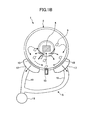
FIGS. 1A and1B are configuration diagrams of a cleaning apparatus of the present invention; -
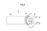
FIG. 2 is a perspective view showing a configuration of a holding part; -
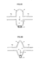
FIGS. 3A to 3D are cross-sectional views showing other shapes of cleaning tanks; -
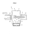
FIG. 4 is a cross-sectional view showing a state where an object to be cleaned is held by a hand of an operator; -
FIGS. 5A and 5B are configuration diagrams of a cleaning medium accelerating nozzle; -
FIG. 6 is a configuration diagram of a dry-type cleaning apparatus having plural cleaning medium accelerating nozzles; -
FIGS. 7A and7B are configuration diagrams of a cleaning apparatus having a deformable mechanism at one opening of a cleaning tank; -
FIGS. 8A to 8C are configuration diagrams of cleaning apparatuses each having a different deformable mechanism at one opening of a cleaning tank; -
FIG. 9 is a configuration diagram of a cleaning apparatus having a separating part at a whole surface of a cleaning tank; -
FIG. 10 is a configuration diagram of a cleaning apparatus in which plural cleaning tank units are provided in series; and -
FIG. 11 is a perspective view showing another configuration of a holding part. -
FIGS. 1A and1B show configurations of acleaning apparatus 1 of the present invention.FIGS. 1A and1B show a front cross-sectional view and a side cross-sectional view of thecleaning apparatus 1, respectively. Thecleaning apparatus 1 includes acleaning tank unit 2, a holdingpart 3, a cleaning medium accelerating part 7, and asuction part 8. In thiscleaning apparatus 1, a deposit (dust, powder, or a stain fixed in a film state) attached on anobject 4 to be cleaned that is held by the holdingpart 3 is removed by colliding cleaningmedia 5 caused to fly by an air flow supplied by the cleaning medium accelerating part 7 with the object to be cleaned. The removed deposit is exhausted outside thecleaning tank unit 2 by thesuction part 8. - The cleaning
medium 5 used in thecleaning apparatus 1 is formed of a thin piece material in a square shape having a side of 5 to 10 mm and a thickness of 0.1 to 0.2 mm, by using any flexible material having resistance against shock, such as ceramic, cloth, paper, and resin. In some cases, it is effective to change the size or material of the cleaningmedium 5 depending on theobject 4 to be cleaned. Appropriate conditions for the cleaningmedium 5 can be selected in accordance with theobject 4 to be cleaned, without being limited to the above-described conditions. - In this manner, when a force of an air flow is applied to the cleaning
medium 5 having a thin piece shape in a direction where a projection area is larger, the cleaningmedium 5 is easily accelerated and caused to fly because the cleaningmedium 5 having a thin piece shape has quite a small mass with respect to air resistance. Moreover, the cleaningmedium 5 has low air resistance in a direction where the projection area is small. When the cleaningmedium 5 flies in that direction, a high speed movement is maintained for a long distance. Therefore, the cleaningmedium 5 has a high energy and a large effect when contacted with theobject 4 to be cleaned. Thus, the deposit (dust, powder, or a stain fixed in a film state) attached on theobject 4 to be cleaned can be effectively removed. By repeating circulation of the cleaningmedium 5, the cleaning medium 5 contacts theobject 4 to be cleaned more frequently. Therefore, a cleaning efficiency of thecleaning apparatus 1 can be enhanced. - In addition, air resistance of the cleaning
medium 5 having a thin piece shape largely changes depending on its posture. Therefore, the cleaningmedium 5 repeatedly contacts theobject 4 to be cleaned by moving in a complicated way such as rapidly changing directions as well as moving along the air flow. Therefore, a high cleaning performance can be exhibited for theobject 4 to be cleaned, having a relatively complicated shape. - The
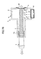
cleaning tank unit 2 includes acleaning tank 6, separatingparts 10, and hollowelongated members cleaning tank 6 includes the cleaning medium accelerating part 7, and the separatingparts 10. Thecleaning tank 6 is formed so that a cleaningmedium flying space 9 in thecleaning tank 6 has, for example, a cylindrical shape. Opposing end parts of the cleaningmedium flying space 9 are sealed with opposing side walls, and circular openings each having such a diameter that allows theobject 4 to be cleaned to pass through are provided at centers of the opposing side walls. The separatingparts 10 are formed of a porous member such as a wire mesh, a plastic mesh, a mesh, a perforated metal, or a slit plate, having small apertures or slits which allow gas or a deposit (dust, powder, or a stain fixed in a film state) to pass through but does not allow the cleaningmedium 5 to pass through. The separatingparts 10 are formed of the above-described member in a smooth shape such as a semi-cylindrical shape, which does not stagnate the cleaningmedium 5, at parts of a wall of the cylindrical shape of thecleaning tank 6 with a predetermined distance provided from the bottommost part of thecleaning tank 6. The hollowelongated members cleaning tank 6. The hollowelongated members cleaning tank 6 to form a movement path of theobject 4 to be cleaned. On the other hand, an opening end of the hollowelongated member 11b, which is at the opposite side to thecleaning tank 6, is covered with aporous member 12 having a mesh or slits that allows an air flow to pass through but does not allow the cleaningmedium 5 to pass through. - The cleaning medium accelerating part 7 includes a cleaning
medium accelerating nozzle 13 having plural injecting holes, a compressedair supplying apparatus 14 formed of a compressor, acontrol valve 15, and anairline 16. The cleaningmedium accelerating nozzle 13 has the plural injecting holes aligned in a straight line at a bottom surface of thecleaning tank 6, passing through thecleaning tank 6. The compressedair supplying apparatus 14 supplies compressed air through theairline 16 having thecontrol valve 15 to the cleaningmedium accelerating nozzles 13 to cause thenozzle 13 to inject an air so that the cleaningmedia 5 fly. Thecontrol valve 15 controls the compressed air supplied by the compressedair supplying apparatus 14. Theairline 16 supplies the compressed air supplied from the compressedair supplying apparatus 14 to the cleaningmedium accelerating nozzle 13. - The
suction part 8 includessuction ducts 17, asuction pipe 19, and asuction apparatus 18. Thesuction ducts 17 remove dust or a deposit (dust, powder, or a stain fixed in a film state) included in the air in thecleaning tank 6 or attached on the cleaningmedium 5 by the separatingparts 10 and sucks them. Thesuction apparatus 18 sucks the air and/or the deposit in thecleaning tank 6 through thesuction pipe 19. Thesuction pipe 19 carries the air and/or deposit, and the like sucked by thesuction ducts 17 through the separatingparts 10. - As shown in a perspective view of
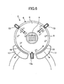
FIG. 2 , the holdingpart 3 includes a cylindrical linear actingarm 20 having an inner diameter slightly smaller (for example, an outer diameter smaller by about several millimeters) than the openings of the hollowelongated members grip part 21 provided rotatably at a leading end of the linear actingarm 20. Thegrip part 21 is provided with ascraper part 22 formed of a mesh, slits, or a dense brush that allows an air flow pass through to a peripheral surface but does not allow the cleaningmedium 5 to pass through, so as to internally contact inner surfaces of the hollowelongated member 11a. - An operation to remove a deposit (powder or dust) attached on the
object 4 to be cleaned by thecleaning apparatus 1 of the present invention is described below. - The
cleaning apparatus 1 drives thesuction apparatus 18 at all times to suck air in thecleaning tank 6 from thesuction ducts 17 through the separatingparts 10. The opening of the hollowelongated member 11a and theporous member 12 of the hollowelongated member 11b generate a suction air flow directed into thecleaning tank 6. In this state, an operator grips theobject 4 to be cleaned by thegrip part 21 of the holdingpart 3, and inserts the holdingpart 3 by which theobject 4 to be cleaned is held, through the opening of the hollowelongated member 11a, to insert theobject 4 to be cleaned into thecleaning tank 6. When theobject 4 to be cleaned held by the holdingpart 3 reaches the cleaningmedium flying space 9, the compressedair supplying apparatus 14 which constitutes the cleaning medium accelerating part 7 is driven. While driving the compressedair supplying apparatus 14, thecontrol valve 15 is opened to supply the compressed air to the cleaningmedium accelerating nozzle 13, and an air flow is generated perpendicularly upward in the cleaningmedium flying space 9 from the cleaningmedium accelerating nozzle 13. By this air flow, the cleaningmedia 5 fly and a part of them collide with theobject 4 to be cleaned, thereby a deposit attached on the surface of theobject 4 to be cleaned is efficiently removed. - A part of the cleaning
media 5 which have collided with theobject 4 to be cleaned fly in a direction of the movement path of the hollowelongated members cleaning tank 6. Further, the cleaningmedia 5 which have not collided with theobject 4 to be cleaned fly straight as they are and collide with a ceiling of thecleaning tank 6. Here, in the vicinity of an inner wall of thecleaning tank 6, the compressed air supplied by the cleaning medium accelerating part 7 flows along an inner wall of the cylinder perpendicularly crossing the opposing side walls of thecleaning tank 6, and at the same time, a circulation air flow is generated by an air flow sucked by thesuction apparatus 18 to flow to the bottom surface of thecleaning tank 6. Therefore, most of the cleaningmedia 5 which have reached the inner wall of thecleaning tank 6 fall due to the circulation air flow and gravity, and slide down to the vicinity of the cleaningmedium accelerating nozzle 13 over the separatingpart 10. A centrifugal force by the circulation air flow is applied to the cleaningmedia 5 moving along the inner wall of the cylinder of thecleaning tank 6. Therefore, a probability that theobject 4 to be cleaned moves from the openings at the centers of the opposing side walls of thecleaning tank 6 into the hollowelongated members media 5 fly in thecleaning tank 6, a leakage of the cleaningmedia 5 into the hollowelongated members media 5 which have leaked into the hollowelongated members elongated members suction apparatus 18 to be collected into thecleaning tank 6. Further, another part of the cleaningmedia 5 which have leaked into the hollowelongated member 11a is prevented by thescraper part 22 of the holdingpart 3 to be collected into thecleaning tank 6. In this manner, the cleaningmedia 5 can be effectively used and a cleaning efficiency can be improved. Moreover, it can be prevented that the cleaningmedia 5 are leaked outside from the movement path of theobject 4 to be cleaned, which is formed of the hollowelongated member 11a. - While the cleaning
media 5 slide down to the vicinity of the cleaningmedia accelerating nozzle 13 by being sucked over the separatingpart 10, a deposit is separated and sucked from the cleaningmedia 5 when passing through the separatingpart 10. The deposit separated by the separatingpart 10 is collected by thesuction apparatus 18 through thesuction duct 17 and thesuction pipe 19. Moreover, the cleaningmedia 5 which have reached the vicinity of the cleaningmedia accelerating nozzle 13 is caused to fly again in a perpendicular upward direction by an air flow injected by the cleaningmedia accelerating nozzle 13. By repeating this operation, a deposit attached on the surface of theobject 4 to be cleaned is removed. - While cleaning the
object 4 to be cleaned by using theflying cleaning media 5, the linear actingarm 20 of the holdingpart 3 is rotated to rotate theobject 4 to be cleaned, and at the same time the linear actingarm 20 is moved back and forth so as to clean a whole surface of theobject 4 to be cleaned. By rotating and moving back and forth theobject 4 to be cleaned by the holdingpart 3 in this manner, the whole surface of theobject 4 to be cleaned having a long size can be surely cleaned. - When the cleaning
medium 5 is caused to fly by the cleaningmedium accelerating nozzle 13 to clean theobject 4 to be cleaned, it is more effective to repeat injecting and stopping of an air flow from the cleaningmedium accelerating nozzle 13 by intermittently driving thecontrol valve 15. By repeating injecting and stopping of the air flow in this manner, the cleaningmedia 5 which have entered the hollowelongated members cleaning tank 6 by a suction air flow generated in the hollowelongated members suction apparatus 18. Further, by rotating theobject 4 to be cleaned at a high speed by using a posture changing function of the holdingpart 3 when the cleaningmedium accelerating nozzle 13 is not injecting an air flow, a centrifugal force is applied to the cleaningmedia 5. Therefore, the cleaningmedia 5 can be more reliably separated from theobject 4 to be cleaned. - In this manner, by circulating the cleaning
media 5 in the cleaningmedium flying space 9 by suppressing a leakage of the cleaningmedia 5 from thecleaning tank 6 so as to collide with theobject 4 to be cleaned at a high frequency, a cleaning performance can be enhanced. Moreover, by moving theobject 4 to be cleaned straight so as to be taken in and out thecleaning tank 6, theobject 4 to be cleaned with a size equal to or larger than thecleaning tank 6 can be cleaned even when thecleaning tank 6 has a small volume. Moreover, by configuring thecleaning tank 6 to have a smaller volume, a flying density of the cleaningmedia 5 can be increased. As a result, a cleaning performance can be considerably improved compared to a conventional cleaning tank. - The description has been made of the case where the
cleaning tank 6 is formed in a cylindrical shape. However, the shape of thecleaning tank 6 is not limited to the cylindrical shape as long as the cleaningmedia 5 circulate along opposing side walls and an inner wall perpendicularly crossing the side walls of thecleaning tank 6 and moves to the position of the cleaningmedium accelerating nozzle 13 without stagnation. For example, thecleaning tank 6 may have a front cross-section in a prism shape as shown inFIG. 3A or a ∽-shape which is along a convection flow as shown inFIG. 3B , or a side cross-section in a U-shape as shown inFIG. 3C or a V-shape as shown inFIG. 3D . - The holding
part 3 may have any configuration as long as it can hold theobject 4 to be cleaned and change the posture of the heldobject 4 to be cleaned. As shown inFIG. 4 , theobject 4 to be cleaned may be directly held by an operator. When the operator holds theobject 4 to be cleaned in this manner, a leakage of the cleaningmedia 5 can be more effectively prevented when thescraper part 22 is mounted on a wrist of the operator. - The above description has been made of the case of generating an air flow in a perpendicular upward direction in the cleaning
medium flying space 9 from the cleaningmedium accelerating nozzle 13. As shown in a front view ofFIG. 5A and a cross-sectional view ofFIG. 5B taken along a line A-A inFIG. 5A , a cleaningmedium accelerating nozzle 13a having two systems of injectingholes cleaning tank 6. Pressurized air to be supplied to the two systems of the injectingholes valve 24 so as to generate an air flow along a cylindrical inner wall of thecleaning tank 6. The cleaningmedium accelerating nozzle 13 may be provided for each path of air flows so that the cleaningmedium 5 is caused to fly along the cylindrical inner wall of thecleaning tank 6 by an air flow alternately generated along the cylindrical inner wall of thecleaning tank 6 from the cleaningmedium accelerating nozzle 13a. Then, the flyingcleaning medium 5 may be collided with theobject 4 to be cleaned by the air flow alternately injected from the cleaningmedium accelerating nozzle 13. - In this manner, by alternately generating air flows at a certain cycle from the two systems of injecting
holes medium 5 flying along the cylindrical inner wall of thecleaning tank 6 with theobject 4 to be cleaned by the air flow alternately injected from the cleaningmedium accelerating nozzle 13, peaks and valleys of a surface of theobject 4 to be cleaned, which has protrusions and recessions, can be cleaned. The whole surface of theobject 4 to be cleaned having a complicated shape can be surely cleaned, and at the same time, a cleaning speed of thecleaning apparatus 1 can be improved. - In the above description, the two systems of the injecting
holes medium accelerating nozzle 13a, however, one injecting hole 23 may be provided for the cleaningmedium accelerating nozzle 13a and an angle of the cleaningmedium accelerating nozzle 13a may be variably set. Moreover, a direction changing mechanism to change a direction of an injected air flow may be provided in the vicinity of the injecting hole 23. The direction changing mechanism may be formed by providing a flow control plate of which an angle is variable or plural injecting holes with different angles so that air flows are simultaneously generated and an angle of the air flow is changed by combining the air flows. - In the above description, the hollow
elongated members cleaning tank 6. However, as shown in a cross-sectional view ofFIGS. 7A and7B , the hollowelongated member 11a may be connected to the opening of one of the side walls of thecleaning tank 6, while adeformable mechanism 25 formed of, for example, a flexible rubber film capable of deforming by a sufficient deforming amount with respect to the direct (linear) acting direction of theobject 4 to be cleaned may be connected to the opening of the other side wall of thecleaning tank 6. - In this manner, in the
cleaning apparatus 1 in which the hollowelongated member 11a is connected to the opening of one of the side walls of thecleaning tank 6 and thedeformable mechanism 25 formed of a flexible rubber film is provided at the opening of the other side wall, theobject 4 to be cleaned is inserted from the hollow elongated member 11 into thecleaning tank 6 in a state where a suction air flow is generated by thesuction apparatus 18. When theobject 4 to be cleaned is cleaned by the cleaningmedia 5 which are caused to fly by injecting an air flow from the cleaningmedium accelerating nozzle 13, an influent air flow (which flows into the hollowelongated member 11a) is generated at an input slot of the hollowelongated member 11a connected to the opening of one of the side walls of thecleaning tank 6. The opening of the other side wall of thecleaning tank 6 is sealed with thedeformable mechanism 25 formed of a flexible rubber film. Thedeformable mechanism 25 is deformed inward of thecleaning tank 6 due to the suction air flow of thesuction apparatus 18. Thus, stagnation of the flyingcleaning media 5 can be prevented. Therefore, the cleaningmedia 5 can be effectively used and a cleaning performance can be improved. - When the
object 4 to be cleaned is further advanced in thecleaning apparatus 1 in this state, a leading end of theobject 4 to be cleaned contacts thedeformable mechanism 25 as shown inFIG. 7A and deforms the rubber film that constitutes thedeformable mechanism 25. In this manner, by protruding (deviating) the leading end of theobject 4 to be cleaned out of thecleaning tank 6, an end part of theobject 4 to be cleaned on the holdingpart 3 side can be accommodated in the cleaningmedium flying space 9 to be cleaned. After the whole surface of theobject 4 to be cleaned is cleaned, injection of an air flow from the cleaningmedium accelerating nozzle 13 is stopped and theobject 4 to be cleaned is pulled back while the suction air flow is generated by thesuction apparatus 18 in thecleaning tank 6. As shown inFIG. 7B , by the reversing of theobject 4 to be cleaned, thedeformable mechanism 25 is restored from the deformation by a negative pressure in thecleaning tank 6 and a restoring force of the rubber film which constitutes thedeformable mechanism 25. At this time, the cleaningmedium 5 stagnant between theobject 4 to be cleaned and the rubber film constituting thedeformable mechanism 25 can be returned into thecleaning tank 6. If necessary, after the whole surface of theobject 4 to be cleaned is cleaned by repeating the advancements in back and forth directions and a stationary state of theobject 4 to be cleaned, theobject 4 to be cleaned is taken out of thecleaning tank 6, thereby the cleaning operation is completed. - As the
deformable mechanism 25 provided at a forward direction of the advancement of theobject 4 to be cleaned in thecleaning tank 6, acornice member 26 as shown inFIG. 8A , acrank mechanism 28 provided with amovable sealing member 27 as shown inFIG. 8B , or a connectingpipe member 29 which has a sealed outer end surface and is extendable in the forward direction of the advancement of theobject 4 to be cleaned may be used to obtain a similar effect. Further, a driving part may be provided for thedeformable mechanism 25 so as to control the deformation and movement of thedeformable mechanism 25 in accordance with a position of theobject 4 to be cleaned. - In this manner, by providing the
deformable mechanism 25 in the forward direction of the advancement of theobject 4 to be cleaned in thecleaning tank 6, the cleaningmedium 5 can be caused to fly efficiently by preventing a leakage or stagnation of the cleaningmedium 5. Further, the whole surface of theobject 4 to be cleaned, which has a longer size than thecleaning tank 6, can be cleaned. - The description has been made on the case where the separating
parts 10 are provided at the parts of the cylindrical wall of thecleaning tank 6 with a predetermined distance provided from the bottommost part of thecleaning tank 6. However, the separatingpart 10 may be provided along the entire surface of the cylindrical wall of thecleaning tank 6 and thesuction duct 17 may be provided in an outer peripheral part of the separatingpart 10 as shown in a front cross-sectional view ofFIG. 9 . In this manner, by providing the separatingpart 10 along the entire surface of the cylindrical wall of thecleaning tank 6 so as to increase an area of the separatingpart 10 formed of a porous member, clogging of the separatingpart 10 can be prevented and a probability that the cleaningmedia 5 contact the separatingpart 10 can be increased. As a result, a deposit attached on the cleaningmedia 5 can be efficiently separated and the cleaning medium 5 from which a stain and the like are removed can be collided again with theobject 4 to be cleaned. Thus, a cleaning efficiency of thecleaning apparatus 1 can be improved. - in the above description, one set of the
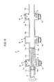
cleaning tank unit 2 is provided for thecleaning apparatus 1. A description is made below on a cleaning apparatus la provided with three sets ofcleaning tank units 2a to 2c arranged in series as shown in a configuration diagram ofFIG. 10 . - The three respective sets of the
cleaning tank units 2a to 2c have the hollowelongated members respective cleaning tanks 6. The hollowelongated member 11b of thecleaning tank unit 2a and the hollowelongated member 11a of thecleaning tank unit 2b are connected to each other. In a manner similar to this, the hollowelongated member 11b of thecleaning tank unit 2b and the hollowelongated member 11a of thecleaning tank unit 2c are connected to each other. In this manner, thecleaning apparatus 1a is constituted. - As shown in a perspective view of
FIG. 11 , the holdingpart 3 of thecleaning apparatus 1a includes thegrip part 21, awire frame 30,scraper parts object 4 to be cleaned is fixed in the holdingpart 3 by thegrip part 21. Thewire frame 30 has openings in such a size that does not prevent the cleaning medium 5 from passing through. Thescraper parts medium 5 to pass through. Thescraper parts wire frame 30 in a movement direction of the holdingpart 3. - The plural cleaning
medium accelerating nozzles 13 provided for thecleaning tanks 6 of thecleaning tank units 2a to 2c can have different air injecting directions from each other with respect to the movement direction of the holdingpart 3. For example, the air injecting direction of the cleaningmedium accelerating nozzle 13 of thecleaning tank unit 2a is set 90° with respect to the movement direction of the holdingpart 3. The air injecting direction of the cleaningmedium accelerating nozzle 13 of thecleaning tank unit 2b is set to 120° with respect to the movement direction of the holdingpart 3. The air injecting direction of the cleaningmedium accelerating nozzle 13 of thecleaning tank unit 2c is set to 60° with respect to the movement direction of the holdingpart 3. In this state, the holdingpart 3 holding theobject 4 to be cleaned is moved from thecleaning tank 2a side. When theobject 4 to be cleaned that is held by the holdingpart 3 is at positions of thecleaning tank units 2a to 2c, air flows are injected from the cleaningmedium accelerating nozzles 13 of thecleaning tank units 2a to 2c to cause the cleaningmedia 5 to fly, thereby theobject 4 to be cleaned is cleaned. - In this manner, by providing the plural
cleaning tank units 2a to 2c in thecleaning apparatus 1a and setting the cleaningmedium accelerating nozzles 13 of thecleaning tank units 2a to 2c to inject air flows at different angles from each other, the cleaningmedia 5 can be collided with theobject 4 to be cleaned at the different directions even when theobject 4 to be cleaned has a complicated shape with protrusions and recessions. As a result, theobject 4 to be cleaned can be cleaned evenly. When there is a sufficient number of thecleaning tank units 2, the holdingpart 3 is not required to be reciprocated, but is only required to be driven in one direction to obtain a required cleaning result. In this case, moreover, theplural holding parts 3 holding theobjects 4 to be cleaned can be inserted in succession to be cleaned. As a result, theplural objects 4 to be cleaned can be successively cleaned in a short time. - Further, the
scraper parts part 3 can prevent a part of the cleaningmedia 5 collided with theobject 4 from being leaked outside thecleaning tank units 2a to 2c. - Moreover, when the holding
part 3 advances straight, thescraper parts media 5 accumulated on the hollowelongated members media 5 can be collected into thecleaning tank 6. Accordingly, an amount of the cleaningmedia 5 flying in thecleaning tank 6 can be maintained to be constant, and the cleaning performance of thecleaning apparatus 1 can be improved. - According to at least one embodiment of the present invention, cleaning media can be caused to fly in a cleaning medium flying space without stagnation. Moreover, the cleaning performance can be maintained by effectively using the cleaning media and stabilizing the amount of flying cleaning media.
- According to at least one embodiment, an object to be cleaned passes through a hollow elongated member and an opening for the object to be cleaned, is inserted at a position facing a cleaning medium accelerating part, and collided with the accelerated cleaning media to be cleaned. By placing the opening for the object to be cleaned at a position that does not face the cleaning medium accelerating part, a leakage of the cleaning media from the cleaning tank is suppressed. Further, by quickly collecting the cleaning media which have leaked into the hollow elongated member connected to the opening for the object to be cleaned into the cleaning tank by a cleaning medium returning part, the number of cleaning media in the cleaning tank is stabilized and the cleaning performance is maintained.
Claims (7)
- A cleaning apparatus for cleaning an object (4) to be cleaned by allowing a cleaning medium (5) contained in the cleaning apparatus (1) and caused to fly by an air flow to collide with the object (4) to be cleaned, comprising:a cleaning tank (6) in which the cleaning medium (5) is caused to fly by the air flow and which has an opening configured to allow the object (4) to be cleaned to pass through;a cleaning medium accelerating part (7) provided at a bottom part of the cleaning tank (6) and configured to inject the air flow to cause the cleaning medium (5) to fly;a cleaning medium returning part (12) configured to return the cleaning medium (5) stagnant in the hollow elongated member(s) (11a, 11b) into the cleaning tank (6);a suction part (8) including suction ducts (17) configured to remove dust or a deposit included in the air in the cleaning tank (6), a suction pipe (19) configured to carry the air and/or the deposit sucked by the suction ducts (17) and a suction apparatus (18) configured to suck the air and/or the deposit in the cleaning tank (6) through the suction pipe (19);a first hollow elongated member (11a) connected outside an opening of the cleaning tank (6), and configured to have substantially the same inner diameter as a diameter of the opening of the cleaning tank (6), and to form a movement path for the object (4) to be cleaned,wherein in an opening to the side wall of the cleaning tank (6) opposite the first hollow elongated member (11a) there is located either a second hollow elongated member (11b) also connected outside an opening of the cleaning tank (6), and configured to have substantially the same inner diameter as a diameter of the opening of the cleaning tank (6), and to form a movement path for the object (4) to be cleaned, or a deformable mechanism (25) connected outside an opening of the cleaning tank (6) and capable of deforming by a sufficient deforming amount with respect to the direct acting direction of the object (4) to be cleaned.
- The cleaning apparatus as claimed in claim 1, wherein the hollow elongated member has a length equal to or more than a length of the object (4) to be cleaned and allows movement of the object (4) to be cleaned within the hollow elongated member.
- The cleaning apparatus as claimed in claim 1 or 2, wherein the cleaning medium accelerating part (7) has a cleaning medium accelerating nozzle (13) having plural injecting holes along the movement path in which the object (4) to be cleaned moves.
- The cleaning apparatus as claimed in any one of claims 1 to 3, wherein the cleaning medium returning part (12) is provided at one of said openings of the hollow elongated member for the object (4) to be cleaned and is deformable by stretching in the direction of forward advancement in the cleaning tank (6) of the object (4) to be cleaned in synchronization with the movement of the object (4) to be cleaned.
- The cleaning apparatus as claimed in any one of claims 1 to 4, further comprising, in the cleaning tank (6), a separating part (10) which allows air or a removed stain to pass through but does not allow the cleaning medium (5) to pass through, and the suction part (8) connected to the separating part (10) and configured to suck air from the cleaning tank (6).
- The cleaning apparatus as claimed in any one of claims 2 to 5, further comprising a holding part (3) having a holder configured to hold the object (4) to be cleaned; and a scraper member (22) configured to seal a space formed between the hollow elongated member (11a, 11b) and the holding part (3) with respect to the cleaning medium (5), in a vicinity of the holder.
- A method for cleaning an object (4) to be cleaned by colliding a cleaning medium (5) caused to fly by an air flow with the object (4) to be cleaned in a cleaning tank (6) containing the cleaning medium and having an opening through which the object (4) to be cleaned can pass through, said method comprising:sucking air in the cleaning tank (6) by a suction part (8), removing dust or a deposit included in the air in the cleaning tank (6) by suction ducts (17) included in the suction part (8) carrying the air and/or the deposit sucked by the suction ducts (17) by a suction pipe (19) and sucking the air and/or the deposit in the cleaning tank (6) through the suction pipe (19) by a suction apparatus (18);injecting an air flow into the cleaning tank (6) in which the object (4) to be cleaned is inserted so as to cause the cleaning medium (5) to fly,inserting the object (4) to be cleaned into the cleaning tank (6) through a first hollow elongated member (11a) for the object (4) to be cleaned, said first hollow elongated member (11a) connected outside an opening of the cleaning tank (6), and configured to have substantially the same inner diameter as a diameter of the opening of the cleaning tank (6), and to form a movement path for the object (4) to be cleaned,returning the cleaning medium (5) stagnant in the hollow elongated member(s) into the cleaning tank (6) by means of a medium returning part (12), andeither advancing the object (4) to be cleaned forward through the cleaning tank (6) and into a second hollow elongated member (11b) also connected outside an opening of the cleaning tank (6), and configured to have substantially the same inner diameter as a diameter of the opening of the cleaning tank (6), and to form a movement path for the object (4) to be cleaned, oradvancing the object (4) to be cleaned forward to deform a deformable mechanism (25) connected outside an opening of the cleaning tank (6) and capable of deforming by a sufficient deforming amount with respect to the direct acting direction of the object (4) to be cleaned.
Applications Claiming Priority (2)
| Application Number | Priority Date | Filing Date | Title |
|---|---|---|---|
| JP2008158618 | 2008-06-18 | ||
| JP2009111799A JP5403407B2 (en) | 2008-06-18 | 2009-05-01 | Cleaning device |
Publications (2)
| Publication Number | Publication Date |
|---|---|
| EP2135687A1 EP2135687A1 (en) | 2009-12-23 |
| EP2135687B1 true EP2135687B1 (en) | 2011-08-24 |
Family
ID=40848434
Family Applications (1)
| Application Number | Title | Priority Date | Filing Date |
|---|---|---|---|
| EP09162888A Not-in-force EP2135687B1 (en) | 2008-06-18 | 2009-06-17 | Cleaning apparatus and cleaning method |
Country Status (5)
| Country | Link |
|---|---|
| US (1) | US8584312B2 (en) |
| EP (1) | EP2135687B1 (en) |
| JP (1) | JP5403407B2 (en) |
| CN (1) | CN101607254B (en) |
| AT (1) | ATE521422T1 (en) |
Families Citing this family (17)
| Publication number | Priority date | Publication date | Assignee | Title |
|---|---|---|---|---|
| JP4770821B2 (en) * | 2007-11-16 | 2011-09-14 | パナソニック株式会社 | Vacuum cleaner |
| JP4531841B2 (en) * | 2008-02-27 | 2010-08-25 | 株式会社リコー | Cleaning device and cleaning method |
| JP5793980B2 (en) | 2010-11-10 | 2015-10-14 | 株式会社リコー | Dry cleaning housing and dry cleaning device |
| JP5712826B2 (en) | 2010-11-17 | 2015-05-07 | 株式会社リコー | Dry cleaning housing and dry cleaning device |
| JP5879903B2 (en) | 2011-02-25 | 2016-03-08 | 株式会社リコー | Dry cleaning housing, dry cleaning device and dry cleaning system |
| JP5953975B2 (en) | 2011-10-26 | 2016-07-20 | 株式会社リコー | Cleaning medium splash prevention member, cleaning object holder and dry cleaning device |
| JP5919786B2 (en) | 2011-12-12 | 2016-05-18 | 株式会社リコー | Dry cleaning housing and dry cleaning device |
| JP5440622B2 (en) * | 2012-01-27 | 2014-03-12 | 株式会社リコー | Dry cleaning device and dry cleaning method |
| JP6492429B2 (en) | 2013-10-15 | 2019-04-03 | 株式会社リコー | Dry cleaning housing, dry cleaning device, and separation plate mounting method |
| KR101375498B1 (en) * | 2013-11-20 | 2014-04-01 | 김영도 | Shoes of inside cleaning and sterilization machine |
| KR101795918B1 (en) | 2015-07-24 | 2017-11-10 | 주식회사 포스코 | Hot dip galvanized and galvannealed steel sheet having higher bake hardening and aging properties, and method for the same |
| CA2946415C (en) * | 2015-11-11 | 2023-11-07 | Engineered Abrasives, Inc. | Part processing and cleaning apparatus and method of same |
| US10569309B2 (en) * | 2015-12-15 | 2020-02-25 | General Electric Company | Equipment cleaning system and method |
| JP6975953B2 (en) * | 2016-12-28 | 2021-12-01 | ヒューグル開発株式会社 | Foreign matter removal device and foreign matter removal method |
| CN107866415A (en) * | 2017-12-21 | 2018-04-03 | 上海芯湃电子科技有限公司 | Carrier band destatics cleaning device |
| DE102019112044A1 (en) * | 2019-05-08 | 2020-11-12 | Ecoclean Gmbh | Cleaning device |
| CN113060190B (en) * | 2021-04-03 | 2022-07-29 | 浙江泰阳建设集团有限公司 | Transport vechicle that construction was used |
Family Cites Families (21)
| Publication number | Priority date | Publication date | Assignee | Title |
|---|---|---|---|---|
| US1910497A (en) * | 1930-01-02 | 1933-05-23 | American Foundry Equip Co | Sand blast gun |
| US2657409A (en) * | 1949-05-06 | 1953-11-03 | Robert A J Dawson | Rowel type pipe cleaning tool |
| US2649757A (en) * | 1950-07-11 | 1953-08-25 | Edward W Sharpe | Coating device for coating elongated objects |
| US3508997A (en) * | 1966-12-01 | 1970-04-28 | John Mckenney Werling | Method and apparatus for cleaning and reconditioning of material containing cans |
| EP0316622B1 (en) | 1987-11-20 | 1993-08-04 | General Electric Company | Method and apparatus for elutriation of shaped particles of polymeric resin |
| US5443801A (en) * | 1990-07-20 | 1995-08-22 | Kew Import/Export Inc. | Endoscope cleaner/sterilizer |
| JP2515833Y2 (en) | 1991-03-27 | 1996-10-30 | スバル興業株式会社 | Cleaning device using flying objects |
| US5265298A (en) * | 1992-02-25 | 1993-11-30 | Raymond Young | Container cleaning system using ionized air flow |
| JP2582321Y2 (en) * | 1992-09-03 | 1998-09-30 | 石川島播磨重工業株式会社 | Cleaning device for incinerator filters |
| CA2103685C (en) * | 1993-08-06 | 1997-11-11 | Charles P. Elliott | Blast cleaning apparatus and method with laterally moving conveyor |
| JP3373050B2 (en) | 1994-05-30 | 2003-02-04 | ナミテイ株式会社 | Surface treatment equipment |
| JP3468995B2 (en) | 1996-07-30 | 2003-11-25 | 澁谷工業株式会社 | Method and apparatus for cleaning resin container |
| US6034351A (en) * | 1998-06-24 | 2000-03-07 | Sato; Katsuhiro | Cleaning apparatus for welding torch nozzle and method of cleaning the same |
| JP2005296853A (en) * | 2004-04-13 | 2005-10-27 | Ricoh Co Ltd | Fine powder removal apparatus |
| JP4598694B2 (en) | 2005-06-22 | 2010-12-15 | 株式会社リコー | Cleaning device and cleaning method |
| JP4580916B2 (en) | 2005-11-02 | 2010-11-17 | 株式会社リコー | Cleaning device and cleaning method |
| FR2900915B1 (en) * | 2006-05-10 | 2008-12-26 | Financ De Gestion Soc Civ Ile | SEALING BUTTON FOR CONVEYOR |
| US7730896B2 (en) | 2006-09-06 | 2010-06-08 | Ricoh Company, Limited | Dry cleaning device and dry cleaning method |
| JP4749287B2 (en) * | 2006-09-06 | 2011-08-17 | 株式会社リコー | Cleaning device |
| US7854648B2 (en) * | 2006-12-15 | 2010-12-21 | Ricoh Company, Ltd. | Cleaning medium and dry cleaning apparatus using the same |
| US20090095160A1 (en) * | 2007-10-12 | 2009-04-16 | Ronald Troxell | Electrostatically charged engine intake filter media |
-
2009
- 2009-05-01 JP JP2009111799A patent/JP5403407B2/en not_active Expired - Fee Related
- 2009-06-15 US US12/484,574 patent/US8584312B2/en not_active Expired - Fee Related
- 2009-06-17 EP EP09162888A patent/EP2135687B1/en not_active Not-in-force
- 2009-06-17 AT AT09162888T patent/ATE521422T1/en not_active IP Right Cessation
- 2009-06-18 CN CN2009101461930A patent/CN101607254B/en not_active Expired - Fee Related
Also Published As
| Publication number | Publication date |
|---|---|
| CN101607254B (en) | 2011-01-05 |
| US20090314312A1 (en) | 2009-12-24 |
| CN101607254A (en) | 2009-12-23 |
| JP5403407B2 (en) | 2014-01-29 |
| US8584312B2 (en) | 2013-11-19 |
| ATE521422T1 (en) | 2011-09-15 |
| EP2135687A1 (en) | 2009-12-23 |
| JP2010023025A (en) | 2010-02-04 |
Similar Documents
| Publication | Publication Date | Title |
|---|---|---|
| EP2135687B1 (en) | Cleaning apparatus and cleaning method | |
| EP1782895B1 (en) | Dry type cleaning apparatus and dry type cleaning method | |
| EP2244847B1 (en) | Cleaning device and cleaning method | |
| US7854648B2 (en) | Cleaning medium and dry cleaning apparatus using the same | |
| JP4898939B2 (en) | Dry cleaning equipment | |
| EP1897628A2 (en) | Dry cleaning device and dry cleaning method | |
| JP2007029945A (en) | Dry cleaning device and dry cleaning method | |
| JP5061053B2 (en) | Dry cleaning apparatus, dry cleaning method, cleaning product cleaned by the dry cleaning apparatus, and method of manufacturing the regenerator | |
| JP4860764B2 (en) | Cleaning device and cleaning method | |
| JP4950329B2 (en) | Cleaning device | |
| JP5101873B2 (en) | Cleaning medium | |
| JP2010279949A5 (en) | ||
| JP2007330947A (en) | Dry cleaning apparatus and method | |
| JP2008062148A (en) | Apparatus and method for dry-cleaning | |
| JP4954030B2 (en) | Cleaning medium and dry cleaning apparatus using the same | |
| JP5298681B2 (en) | Dry cleaning equipment | |
| JP5310812B2 (en) | Cleaning medium and dry cleaning apparatus using the same | |
| JP4902399B2 (en) | Dry cleaning equipment | |
| JP2008062145A (en) | Apparatus and method for dry-cleaning | |
| JP5218615B2 (en) | Dry cleaning equipment | |
| JP2012210617A (en) | Washing apparatus |
Legal Events
| Date | Code | Title | Description |
|---|---|---|---|
| PUAI | Public reference made under article 153(3) epc to a published international application that has entered the european phase |
Free format text: ORIGINAL CODE: 0009012 |
|
| 17P | Request for examination filed |
Effective date: 20090617 |
|
| AK | Designated contracting states |
Kind code of ref document: A1 Designated state(s): AT BE BG CH CY CZ DE DK EE ES FI FR GB GR HR HU IE IS IT LI LT LU LV MC MK MT NL NO PL PT RO SE SI SK TR |
|
| 17Q | First examination report despatched |
Effective date: 20100520 |
|
| GRAP | Despatch of communication of intention to grant a patent |
Free format text: ORIGINAL CODE: EPIDOSNIGR1 |
|
| GRAS | Grant fee paid |
Free format text: ORIGINAL CODE: EPIDOSNIGR3 |
|
| GRAA | (expected) grant |
Free format text: ORIGINAL CODE: 0009210 |
|
| AK | Designated contracting states |
Kind code of ref document: B1 Designated state(s): AT BE BG CH CY CZ DE DK EE ES FI FR GB GR HR HU IE IS IT LI LT LU LV MC MK MT NL NO PL PT RO SE SI SK TR |
|
| REG | Reference to a national code |
Ref country code: GB Ref legal event code: FG4D |
|
| REG | Reference to a national code |
Ref country code: CH Ref legal event code: EP |
|
| REG | Reference to a national code |
Ref country code: IE Ref legal event code: FG4D |
|
| REG | Reference to a national code |
Ref country code: DE Ref legal event code: R096 Ref document number: 602009002245 Country of ref document: DE Effective date: 20111020 |
|
| REG | Reference to a national code |
Ref country code: NL Ref legal event code: VDEP Effective date: 20110824 |
|
| LTIE | Lt: invalidation of european patent or patent extension |
Effective date: 20110824 |
|
| PG25 | Lapsed in a contracting state [announced via postgrant information from national office to epo] |
Ref country code: IS Free format text: LAPSE BECAUSE OF FAILURE TO SUBMIT A TRANSLATION OF THE DESCRIPTION OR TO PAY THE FEE WITHIN THE PRESCRIBED TIME-LIMIT Effective date: 20111224 Ref country code: PT Free format text: LAPSE BECAUSE OF FAILURE TO SUBMIT A TRANSLATION OF THE DESCRIPTION OR TO PAY THE FEE WITHIN THE PRESCRIBED TIME-LIMIT Effective date: 20111226 Ref country code: LT Free format text: LAPSE BECAUSE OF FAILURE TO SUBMIT A TRANSLATION OF THE DESCRIPTION OR TO PAY THE FEE WITHIN THE PRESCRIBED TIME-LIMIT Effective date: 20110824 Ref country code: NL Free format text: LAPSE BECAUSE OF FAILURE TO SUBMIT A TRANSLATION OF THE DESCRIPTION OR TO PAY THE FEE WITHIN THE PRESCRIBED TIME-LIMIT Effective date: 20110824 Ref country code: SE Free format text: LAPSE BECAUSE OF FAILURE TO SUBMIT A TRANSLATION OF THE DESCRIPTION OR TO PAY THE FEE WITHIN THE PRESCRIBED TIME-LIMIT Effective date: 20110824 Ref country code: FI Free format text: LAPSE BECAUSE OF FAILURE TO SUBMIT A TRANSLATION OF THE DESCRIPTION OR TO PAY THE FEE WITHIN THE PRESCRIBED TIME-LIMIT Effective date: 20110824 Ref country code: NO Free format text: LAPSE BECAUSE OF FAILURE TO SUBMIT A TRANSLATION OF THE DESCRIPTION OR TO PAY THE FEE WITHIN THE PRESCRIBED TIME-LIMIT Effective date: 20111124 Ref country code: HR Free format text: LAPSE BECAUSE OF FAILURE TO SUBMIT A TRANSLATION OF THE DESCRIPTION OR TO PAY THE FEE WITHIN THE PRESCRIBED TIME-LIMIT Effective date: 20110824 |
|
| REG | Reference to a national code |
Ref country code: AT Ref legal event code: MK05 Ref document number: 521422 Country of ref document: AT Kind code of ref document: T Effective date: 20110824 |
|
| PG25 | Lapsed in a contracting state [announced via postgrant information from national office to epo] |
Ref country code: GR Free format text: LAPSE BECAUSE OF FAILURE TO SUBMIT A TRANSLATION OF THE DESCRIPTION OR TO PAY THE FEE WITHIN THE PRESCRIBED TIME-LIMIT Effective date: 20111125 Ref country code: AT Free format text: LAPSE BECAUSE OF FAILURE TO SUBMIT A TRANSLATION OF THE DESCRIPTION OR TO PAY THE FEE WITHIN THE PRESCRIBED TIME-LIMIT Effective date: 20110824 Ref country code: PL Free format text: LAPSE BECAUSE OF FAILURE TO SUBMIT A TRANSLATION OF THE DESCRIPTION OR TO PAY THE FEE WITHIN THE PRESCRIBED TIME-LIMIT Effective date: 20110824 Ref country code: SI Free format text: LAPSE BECAUSE OF FAILURE TO SUBMIT A TRANSLATION OF THE DESCRIPTION OR TO PAY THE FEE WITHIN THE PRESCRIBED TIME-LIMIT Effective date: 20110824 Ref country code: LV Free format text: LAPSE BECAUSE OF FAILURE TO SUBMIT A TRANSLATION OF THE DESCRIPTION OR TO PAY THE FEE WITHIN THE PRESCRIBED TIME-LIMIT Effective date: 20110824 Ref country code: CY Free format text: LAPSE BECAUSE OF FAILURE TO SUBMIT A TRANSLATION OF THE DESCRIPTION OR TO PAY THE FEE WITHIN THE PRESCRIBED TIME-LIMIT Effective date: 20110824 |
|
| PG25 | Lapsed in a contracting state [announced via postgrant information from national office to epo] |
Ref country code: BE Free format text: LAPSE BECAUSE OF FAILURE TO SUBMIT A TRANSLATION OF THE DESCRIPTION OR TO PAY THE FEE WITHIN THE PRESCRIBED TIME-LIMIT Effective date: 20110824 |
|
| PG25 | Lapsed in a contracting state [announced via postgrant information from national office to epo] |
Ref country code: SK Free format text: LAPSE BECAUSE OF FAILURE TO SUBMIT A TRANSLATION OF THE DESCRIPTION OR TO PAY THE FEE WITHIN THE PRESCRIBED TIME-LIMIT Effective date: 20110824 Ref country code: CZ Free format text: LAPSE BECAUSE OF FAILURE TO SUBMIT A TRANSLATION OF THE DESCRIPTION OR TO PAY THE FEE WITHIN THE PRESCRIBED TIME-LIMIT Effective date: 20110824 |
|
| PG25 | Lapsed in a contracting state [announced via postgrant information from national office to epo] |
Ref country code: EE Free format text: LAPSE BECAUSE OF FAILURE TO SUBMIT A TRANSLATION OF THE DESCRIPTION OR TO PAY THE FEE WITHIN THE PRESCRIBED TIME-LIMIT Effective date: 20110824 Ref country code: RO Free format text: LAPSE BECAUSE OF FAILURE TO SUBMIT A TRANSLATION OF THE DESCRIPTION OR TO PAY THE FEE WITHIN THE PRESCRIBED TIME-LIMIT Effective date: 20110824 Ref country code: IT Free format text: LAPSE BECAUSE OF FAILURE TO SUBMIT A TRANSLATION OF THE DESCRIPTION OR TO PAY THE FEE WITHIN THE PRESCRIBED TIME-LIMIT Effective date: 20110824 |
|
| PG25 | Lapsed in a contracting state [announced via postgrant information from national office to epo] |
Ref country code: DK Free format text: LAPSE BECAUSE OF FAILURE TO SUBMIT A TRANSLATION OF THE DESCRIPTION OR TO PAY THE FEE WITHIN THE PRESCRIBED TIME-LIMIT Effective date: 20110824 |
|
| PLBE | No opposition filed within time limit |
Free format text: ORIGINAL CODE: 0009261 |
|
| STAA | Information on the status of an ep patent application or granted ep patent |
Free format text: STATUS: NO OPPOSITION FILED WITHIN TIME LIMIT |
|
| 26N | No opposition filed |
Effective date: 20120525 |
|
| REG | Reference to a national code |
Ref country code: DE Ref legal event code: R097 Ref document number: 602009002245 Country of ref document: DE Effective date: 20120525 |
|
| PG25 | Lapsed in a contracting state [announced via postgrant information from national office to epo] |
Ref country code: MC Free format text: LAPSE BECAUSE OF NON-PAYMENT OF DUE FEES Effective date: 20120630 |
|
| PG25 | Lapsed in a contracting state [announced via postgrant information from national office to epo] |
Ref country code: MK Free format text: LAPSE BECAUSE OF FAILURE TO SUBMIT A TRANSLATION OF THE DESCRIPTION OR TO PAY THE FEE WITHIN THE PRESCRIBED TIME-LIMIT Effective date: 20110824 |
|
| REG | Reference to a national code |
Ref country code: IE Ref legal event code: MM4A |
|
| PG25 | Lapsed in a contracting state [announced via postgrant information from national office to epo] |
Ref country code: ES Free format text: LAPSE BECAUSE OF FAILURE TO SUBMIT A TRANSLATION OF THE DESCRIPTION OR TO PAY THE FEE WITHIN THE PRESCRIBED TIME-LIMIT Effective date: 20111205 Ref country code: IE Free format text: LAPSE BECAUSE OF NON-PAYMENT OF DUE FEES Effective date: 20120617 |
|
| PG25 | Lapsed in a contracting state [announced via postgrant information from national office to epo] |
Ref country code: BG Free format text: LAPSE BECAUSE OF FAILURE TO SUBMIT A TRANSLATION OF THE DESCRIPTION OR TO PAY THE FEE WITHIN THE PRESCRIBED TIME-LIMIT Effective date: 20111124 |
|
| PG25 | Lapsed in a contracting state [announced via postgrant information from national office to epo] |
Ref country code: MT Free format text: LAPSE BECAUSE OF FAILURE TO SUBMIT A TRANSLATION OF THE DESCRIPTION OR TO PAY THE FEE WITHIN THE PRESCRIBED TIME-LIMIT Effective date: 20110824 |
|
| REG | Reference to a national code |
Ref country code: CH Ref legal event code: PL |
|
| PG25 | Lapsed in a contracting state [announced via postgrant information from national office to epo] |
Ref country code: LI Free format text: LAPSE BECAUSE OF NON-PAYMENT OF DUE FEES Effective date: 20130630 Ref country code: CH Free format text: LAPSE BECAUSE OF NON-PAYMENT OF DUE FEES Effective date: 20130630 Ref country code: TR Free format text: LAPSE BECAUSE OF FAILURE TO SUBMIT A TRANSLATION OF THE DESCRIPTION OR TO PAY THE FEE WITHIN THE PRESCRIBED TIME-LIMIT Effective date: 20110824 |
|
| PG25 | Lapsed in a contracting state [announced via postgrant information from national office to epo] |
Ref country code: LU Free format text: LAPSE BECAUSE OF NON-PAYMENT OF DUE FEES Effective date: 20120617 |
|
| PG25 | Lapsed in a contracting state [announced via postgrant information from national office to epo] |
Ref country code: HU Free format text: LAPSE BECAUSE OF FAILURE TO SUBMIT A TRANSLATION OF THE DESCRIPTION OR TO PAY THE FEE WITHIN THE PRESCRIBED TIME-LIMIT Effective date: 20090617 |
|
| REG | Reference to a national code |
Ref country code: FR Ref legal event code: PLFP Year of fee payment: 8 |
|
| REG | Reference to a national code |
Ref country code: FR Ref legal event code: PLFP Year of fee payment: 9 |
|
| REG | Reference to a national code |
Ref country code: FR Ref legal event code: PLFP Year of fee payment: 10 |
|
| PGFP | Annual fee paid to national office [announced via postgrant information from national office to epo] |
Ref country code: DE Payment date: 20180625 Year of fee payment: 10 |
|
| PGFP | Annual fee paid to national office [announced via postgrant information from national office to epo] |
Ref country code: FR Payment date: 20180620 Year of fee payment: 10 |
|
| PGFP | Annual fee paid to national office [announced via postgrant information from national office to epo] |
Ref country code: GB Payment date: 20180620 Year of fee payment: 10 |
|
| REG | Reference to a national code |
Ref country code: DE Ref legal event code: R119 Ref document number: 602009002245 Country of ref document: DE |
|
| GBPC | Gb: european patent ceased through non-payment of renewal fee |
Effective date: 20190617 |
|
| PG25 | Lapsed in a contracting state [announced via postgrant information from national office to epo] |
Ref country code: GB Free format text: LAPSE BECAUSE OF NON-PAYMENT OF DUE FEES Effective date: 20190617 Ref country code: DE Free format text: LAPSE BECAUSE OF NON-PAYMENT OF DUE FEES Effective date: 20200101 |
|
| PG25 | Lapsed in a contracting state [announced via postgrant information from national office to epo] |
Ref country code: FR Free format text: LAPSE BECAUSE OF NON-PAYMENT OF DUE FEES Effective date: 20190630 |