EP1897628A2 - Dry cleaning device and dry cleaning method - Google Patents
Dry cleaning device and dry cleaning method Download PDFInfo
- Publication number
- EP1897628A2 EP1897628A2 EP07253501A EP07253501A EP1897628A2 EP 1897628 A2 EP1897628 A2 EP 1897628A2 EP 07253501 A EP07253501 A EP 07253501A EP 07253501 A EP07253501 A EP 07253501A EP 1897628 A2 EP1897628 A2 EP 1897628A2
- Authority
- EP
- European Patent Office
- Prior art keywords
- cleaning
- medium
- air
- circulation
- unit
- Prior art date
- Legal status (The legal status is an assumption and is not a legal conclusion. Google has not performed a legal analysis and makes no representation as to the accuracy of the status listed.)
- Granted
Links
Images


Classifications
-
- G—PHYSICS
- G03—PHOTOGRAPHY; CINEMATOGRAPHY; ANALOGOUS TECHNIQUES USING WAVES OTHER THAN OPTICAL WAVES; ELECTROGRAPHY; HOLOGRAPHY
- G03G—ELECTROGRAPHY; ELECTROPHOTOGRAPHY; MAGNETOGRAPHY
- G03G21/00—Arrangements not provided for by groups G03G13/00 - G03G19/00, e.g. cleaning, elimination of residual charge
-
- B—PERFORMING OPERATIONS; TRANSPORTING
- B08—CLEANING
- B08B—CLEANING IN GENERAL; PREVENTION OF FOULING IN GENERAL
- B08B7/00—Cleaning by methods not provided for in a single other subclass or a single group in this subclass
- B08B7/02—Cleaning by methods not provided for in a single other subclass or a single group in this subclass by distortion, beating, or vibration of the surface to be cleaned
-
- B—PERFORMING OPERATIONS; TRANSPORTING
- B24—GRINDING; POLISHING
- B24C—ABRASIVE OR RELATED BLASTING WITH PARTICULATE MATERIAL
- B24C5/00—Devices or accessories for generating abrasive blasts
-
- B—PERFORMING OPERATIONS; TRANSPORTING
- B24—GRINDING; POLISHING
- B24C—ABRASIVE OR RELATED BLASTING WITH PARTICULATE MATERIAL
- B24C7/00—Equipment for feeding abrasive material; Controlling the flowability, constitution, or other physical characteristics of abrasive blasts
- B24C7/0046—Equipment for feeding abrasive material; Controlling the flowability, constitution, or other physical characteristics of abrasive blasts the abrasive material being fed in a gaseous carrier
-
- B—PERFORMING OPERATIONS; TRANSPORTING
- B24—GRINDING; POLISHING
- B24C—ABRASIVE OR RELATED BLASTING WITH PARTICULATE MATERIAL
- B24C9/00—Appurtenances of abrasive blasting machines or devices, e.g. working chambers, arrangements for handling used abrasive material
Definitions
- the present invention generally relates to an image forming apparatus, and specifically relates to a technology for performing dry cleaning of components used in an image forming apparatus.
- Some conventional methods i.e., wet cleaning methods, use water or solvent for cleaning the toner.
- wet cleaning methods use water or solvent for cleaning the toner.
- Some other conventional methods i.e., dry cleaning methods, use air blow for cleaning the toner.
- cleaning performance is not sufficient for removing toner attached with strong adhesive force, an extra process is necessary for manually removing toner using a cloth or the like.
- the cleaning process is considered as one of bottleneck processes in a product reusing/recycling process.
- Some still other conventional methods i.e., blast cleaning methods, use dry ice for the toner.
- blast cleaning methods use dry ice for the toner.
- these methods have higher running costs and they put a lot of burden on the environment because they use a large amount of dry ice.
- Japanese Patent No. 3288462 discloses a dry cleaning device that removes dust attached to a cleaning target object.
- the dry cleaning device agitates an electrified cleaning target object with an elastically flexible contact member in a rotating cylinder to neutralize the cleaning target object, so that adhesive force of the dust can be weakened, and the dust can be removed from the cleaning target object.
- it is difficult to remove dust with strong adhesive force because contact force between the contact member and the cleaning target object due to agitation is not sufficient.
- Japanese Patent No. 2889547 discloses a technology for removing attachment from a cleaning target object by blowing particles finely cut from a small sphere or a wire rod made of steel, aluminum or stainless to the cleaning target object.
- Japanese Patent No. 3468995 discloses a technology for a shot blast method of removing dust and dirt from a container made of resin by blowing high-velocity air containing particulate solids to a surface of the container.
- Japanese Patent Application Laid-Open No. 2005-329292 discloses a dry cleaning method of removing attachment from a cleaning target object.
- a particulate cleaning medium that adsorbs fine particles is introduced into a cleaning target container, and a cleaning nozzle is put into an opening portion of the cleaning target container.
- High-velocity air is injected into the cleaning target container and discharged from the cleaning nozzle to blow up the cleaning medium inside the cleaning target container.
- the cleaning medium that has been blown up removes particles attached to internal surfaces of the cleaning target container.
- the cleaning medium collides with a mesh portion at an end portion of the cleaning nozzle, so that fine particles adsorbed on the cleaning medium is removed and filtered to make it possible to reuse the cleaning medium.
- Recycled cleaning medium is re-blown up by air to repeatedly clean the cleaning target container.
- the shot blast method disclosed in the Japanese Patents No. 2889547 and No. 3468995 because a small piece or a particulate solid finely cut from a metal small sphere or a wire rod is used, a surface of the cleaning target object is scratched and scrubbed, making the surface rough during a process of removing dust from the cleaning target object. Therefore, the shot blast method is not suitable when it is not allowed to scratch the cleaning target object.
- a dry cleaning device including a circulation-air generating unit that generates high-velocity air inside a cleaning tank to flow up flexible flaked-shaped cleaning medium present in the cleaning tank; a cleaning-medium accelerating unit that accelerates the cleaning medium flowing in the cleaning tank so that the cleaning medium collides with a cleaning target object thereby separating particles sticking onto the cleaning target object; and a cleaning-medium recycle unit that sucks the particles separated from the cleaning target object and recycles the cleaning medium.
- a dry cleaning method including delivering a flaked-shaped flexible cleaning media accumulated on a surface of a cleaning tank, by circulation air flowing along surfaces of the cleaning tank; flowing up the flaked-shaped flexible cleaning media delivered at the delivering in the cleaning tank; causing the cleaning media flown at the flowing up to collide with a cleaning target object by high-velocity air; and removing particles sticking to the cleaning target object.
- Fig. 1 is a schematic diagram of a dry cleaning device 1 according to a first embodiment of the present invention.
- the dry cleaning device 1 removes various dusts 3, such as toner, attached to a cleaning target object 2 by using a cleaning medium 4 flown by high-velocity air as shown in Fig. 2.
- the dry cleaning device 1 includes a cleaning tank 5, a circulation-air generating unit 6, a cleaning-medium accelerating unit 7, and a cleaning-medium recycle unit 8.
- the cleaning medium 4 used in the dry cleaning device 1 can be formed in one of granular shape, stick shape, tubular shape, fibriform, flaked shape, and the like, which is made of one of metals, ceramics, synthetic resin, sponge, fabric, and the like.
- a shape and material of the cleaning medium 4 can be determined depending on characteristics of a shape and material of the cleaning target object 2 or a particle size or attachment strength of the dust 3 attached to the cleaning target object 2.
- a preferable size is such that its area is in a range between 1 square millimeter (mm 2 ) and 1000 mm 2 , and its thickness is in a range between 1 micrometer ( ⁇ m) and 500 ⁇ m.
- the cleaning medium 4 made of resin film, paper, or metal flake, in a flaked-shape.
- the cleaning medium 4 When the cleaning medium 4 is in a flaked shape, when the cleaning medium 4 collides with the cleaning target object 2 at an edge portion of the cleaning medium 4, contact force is concentrated on the edge portion, enabling the cleaning medium 4 to obtain force necessary for removing the dust 3 even though mass of the cleaning medium 4 is small. Because the cleaning medium 4 gets bent and loses applied force when the contact force to the cleaning target object 2 increases, unwanted extra force is not applied to the cleaning target object 2. Accordingly, the cleaning target object 2 hardly gets damaged unlike a general blast shot material or an abrasive for barell finishing. Furthermore, inelastic collision occurs between the flaked-shaped cleaning medium 4 and the cleaning target object 2 largely due to viscous drag of air applied when the cleaning medium 4 is bent caused by collision with the cleaning target object 2.
- the cleaning medium 4 is hardly bounced.
- the cleaning medium 4 slides across a surface of the cleaning target object 2, contacting a wide area of the surface by a single collision. Due to scratching action or scrubbing action caused by the contact, a parallel force is applied to a contact surface of the dust 3 attached to the cleaning target object 2. As a result, it is possible to remove the dust 3 from the cleaning target object 2 with small force, increasing cleaning efficiency.
- the cleaning tank 5 is formed in substantially rectangular solid with a hollow body, and includes a cleaning-target loading port 9 on its top surface for loading the cleaning target object 2, an opening portion on its bottom portion, a cover 10, which can be flexibly opened and closed, on the cleaning-target loading port 9, and the cleaning-medium recycle unit 8 at an opening portion of its bottom portion.
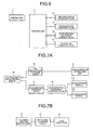
- the circulation-air generating unit 6 is arranged as shown in Fig. 3, forming a circulation path of circulation air on internal surfaces of both side surfaces, the bottom surface, and the top surface of the cleaning tank 5.
- Each of corner portions of the internal surfaces constituting the circulation path is formed in R shape as shown in Fig.
- the predetermined angle ⁇ is preferably determined between 120° and 150° for circulating the circulation air with less resistance.
- each of the corner portions of the internal surfaces with the circulation path is formed in a circular shape or with a predetermined angle between each of adjacent side surfaces. Therefore, the cleaning medium can be delivered without colliding with the internal surfaces. As a result, it is possible to effectively deliver the cleaning medium, increasing cleaning efficiency, and to deliver the cleaning medium with less air supplied, realizing energy saving.
- the circulation-air generating unit 6 includes an inlet portion 62 having an inlet opening 61 with a large diameter, and an outlet portion 64 having a compressed-air supply opening 63 arranged on a periphery of an outlet side of the inlet portion 62.
- the circulation-air generating unit 6 inlets air from the inlet portion 62 by high-velocity airflow supplied from the compressed-air supply opening 63 generated toward an outlet opening 65 of the outlet portion 64, and outlets air with amount of several times to dozens of times of amount of compressed air supplied from the compressed-air supply opening 63.
- the circulation-air generating unit 6 is arranged on a side surface constituting the circulation path near the bottom portion of the cleaning tank 5, with the inlet opening 61 side up while the outlet opening 65 side down.
- the cleaning-medium accelerating unit 7 includes a plurality of acceleration nozzles 71a arrayed on a front surface orthogonal to an internal surface constituting the circulation path, and a plurality of acceleration nozzles 71b arrayed on a back surface facing the front surface with the acceleration nozzles 71a arranged.
- the cleaning-medium accelerating unit 7 blowouts compressed air supplied from a compressed-air source, such as a compressor and a compression tank, inside the cleaning tank 5 via each of the acceleration nozzles 71a and 71b to cause the cleaning medium 4 to collide with the cleaning target object 2. It is preferable to use a blowout nozzle, like the circulation-air generating unit 6, for the acceleration nozzles 71a and 71b.
- the cleaning-medium accelerating unit 7 arranged on a surface orthogonal to the surface constituting the circulation path of the circulation air inside the cleaning tank, and with the nozzle of the cleaning-medium accelerating unit 7 embedded inside the surface of the cleaning tank, it is possible to avoid interference in circulation of the circulation air and effectively cause the cleaning medium to collide with the cleaning target object.
- the cleaning-medium recycle unit 8 includes a separation member 81 and a hood 82 arranged on an internal surface of the bottom portion of the cleaning tank 5, forming a closed space as shown in a perspective view of Fig. 5A and a partial cross section of Fig. 5B.
- the closed space is connected to a dust collector (not shown) including a negative-pressure generating source via a suction tube 11, such as a hose, to generate negative pressure in the hood 82.
- the separation member 81 includes a plurality of small poles and slits 83 in a size through which air and particles can pass while the cleaning medium 4 cannot pass, and are made of porous member, such as metal, plastic mesh, mesh, punched metal plate, and slit plate. With this configuration, the separation member 81 removes dust removed from the cleaning target object 2, and eliminates the cleaning medium 4 worn and chipped by collision with the cleaning target object 2, or the cleaning medium 4 with degraded elasticity due to long-term use.
- the cleaning-medium recycle unit By arranging the cleaning-medium recycle unit at the bottom portion of the cleaning tank, it is possible to increase possibility that the cleaning medium, which has been fallen down the bottom portion of the cleaning tank by gravitation, passes through the cleaning-medium recycle unit, increasing efficiency of recycling the cleaning medium. As a result, the cleanness of the cleaning medium can be improved, improving quality in cleaning.
- a controller 12 of the dry cleaning device 1 includes an air-circulation solenoid valve 14, an acceleration solenoid valve 15, an acceleration-switching control valve 16, and a recycling solenoid valve 17, which are connected to the controller 12 with one another, and controls each of the solenoid valves by a drive signal from a driving unit 13, as shown in a block diagram of Fig. 6 and pipeline diagrams shown in Figs. 7A and 7B.
- the air-circulation solenoid valve 14 performs conduction and non-conduction of an air pipe for supplying compressed air from a compressed-air supplying device 18 to the circulation-air generating unit 6.
- the acceleration solenoid valve 15 performs conduction and non-conduction of an air pipe for supplying compressed air to the cleaning-medium accelerating unit 7.
- the acceleration-switching control valve 16 switches directions of flow of compressed air to be supplied to the acceleration nozzles 71a and 71b respectively arranged on side surfaces of the cleaning-medium accelerating unit 7.
- the recycling solenoid valve 17 performs conduction and non-conduction of the suction tube 11 connecting the cleaning-medium recycle unit 8 to a dust collector 19.
- the flaked-shaped cleaning medium 4 is introduced into the cleaning tank 5 and accumulated on the separation member 81 of the cleaning-medium recycle unit 8. Subsequently, the cleaning target object 2 held by the work holding unit 20 is loaded from the cleaning-target loading port 9 by the work moving unit 21 and set at an initial position. The cover 10 is closed to seal off the cleaning tank 5.
- the controller 12 Upon receiving a cleaning start signal by an operation of the driving unit 13, the controller 12 opens the air-circulation solenoid valve 14 and supplies compressed air to the circulation-air generating unit 6 from the compressed-air supplying device 18, such as a compressor, so that the circulation-air generating unit 6 generates circulation air that flows along the circulation path arranged on the internal surfaces of the cleaning tank 5.
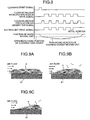
- the circulation air flows along the separation member 81, so that the circulation air acts on the flaked-shaped cleaning medium 4 accumulated on the separation member 81 from a longitudinal direction as shown in Fig. 9A, and gradually chips away accumulation of the cleaning medium 4 from an upper portion of the accumulation.
- the cleaning medium 4 is delivered and flown up in the cleaning tank 5 as shown in Figs. 9B and 9C. Because the circulation air for flowing up the cleaning medium 4 is directly blown from the circulation-air generating unit 6 into the cleaning tank 5, large impact force can be applied to the accumulated cleaning medium 4. Therefore, it is possible to assuredly flow up the accumulated cleaning medium 4 by the circulation air.
- the circulation-air generating unit generates the circulation air that flows along the surface of the cleaning medium accumulated on the cleaning-medium recycle unit. Therefore, it is possible to apply large force for flowing up the accumulated cleaning medium to a large amount of the cleaning media, and circulate the cleaning medium along the internal surfaces of the cleaning tank. As a result, cleaning efficiency can be improved.
- the circulation air is not dispersed and its force is not lost upon flowing. Therefore, it is possible to effectively apply the force of the circulation air to the cleaning medium accumulated on the bottom portion of the cleaning tank. Furthermore, it is possible to deliver and flow up the cleaning medium even with small number of the circulation-air generating units and small amount of air supplied to the circulation-air generating unit. As a result, it is possible to suppress amount of energy necessary for cleaning.
- the cleaning medium 4 is delivered by air using a duct or a hose, the cleaning medium 4 may be clogged in the duct or the hose.
- the circulation path of the circulation air is formed on the internal surfaces of the cleaning tank 5 in the first embodiment, it is possible to avoid clogging the cleaning medium 4 in the circulation path, resulting in flowing up the cleaning medium 4 in the cleaning tank 5.
- circulation air for delivering and flowing up the flaked-shaped flexible cleaning medium flows along the internal surfaces of the cleaning tank, so that the circulation air is not dispersed and its force is not lost. Therefore, it is possible to effectively apply force of the circulation air to the cleaning medium accumulated on the cleaning tank, delivering and flowing up a large amount of the cleaning media with less amount of air supplied. As a result, energy consumption necessary for cleaning can be suppressed. Furthermore, even when once-removed dust is re-attached to the internal surfaces of the cleaning tank, the internal surfaces can be continuously cleaned because a large amount of the cleaning media is circulating. Therefore, it is possible to reduce operations in maintenance, such as cleaning, of the cleaning tank.
- the circulation-air generating unit 6 that generates circulation air is arranged with the inlet opening 61 side up and the outlet opening 65 side down, around the bottom portion of a side surface constituting the circulation path in the cleaning tank 5. Therefore, it is possible to apply air with strong force to the cleaning medium 4 accumulated on the separation member 81 on the bottom portion of the cleaning tank 5, along a bottom surface of the cleaning tank 5. As a result, it is possible to deliver the cleaning medium 4 along the internal surfaces of the cleaning tank 5 to an area away from the outlet opening 65.
- the cleaning media 4 introduced into the inlet opening 61 are dispersed, reducing space density. Therefore, the cleaning medium 4 hardly clogs the inlet opening 61, resulting in stably generating the circulation air.
- the controller 12 closes the air-circulation solenoid valve 14 when a predetermined time elapsed, and causes the circulation-air generating unit 6 to stop generating the circulation air. Subsequently, the controller 12 causes the work moving unit 21 to move down the cleaning target object 2 from the initial position, opens the acceleration solenoid valve 15 to supply compressed air to the cleaning-medium accelerating unit 7 via the acceleration-switching control valve 16, so that compressed air is blown out from the acceleration nozzle 71a of the cleaning-medium accelerating unit 7. The controller 12 opens the recycling solenoid valve 17 to conduct the cleaning-medium recycle unit 8 to the dust collector 19, and generates negative pressure in the hood 82.
- the cleaning medium 4 flown by the circulation air is fallen down.
- the falling down cleaning medium 4 is caused to collide with the cleaning target object 2 by the compressed air blown from the acceleration nozzle 71a, removing the dust 3 attached to a surface of the cleaning target object 2.
- the dust 3 removed from the cleaning target object 2 and the cleaning medium 4 with the dust attached due to collision with the cleaning target object 2 are fallen by gravity, and accumulated on the separation member 81 of the cleaning-medium recycle unit 8 that is vacuuming air due to the negative pressure inside the hood 82.
- the dust fallen on the separation member 81 and the dust attached to the cleaning medium 4 are vacuumed into the hood 82 due to the negative pressure inside the hood 82, and collected by the dust collector 19. As a result, the cleaning medium 4 with the dust attached can be effectively recycled.
- the controller 12 Upon blowing compressed air from the acceleration nozzle 71a for a predetermined time period, the controller 12 closes the acceleration solenoid valve 15 and the recycling solenoid valve 17, and stops operations of the cleaning-medium accelerating unit 7 and the cleaning-medium recycle unit 8.
- the recycling solenoid valve 17 When the recycling solenoid valve 17 is closed, the negative pressure inside the hood 82 is released, so that vacuum force of the hood 82 to the cleaning medium 4 accumulated on the separation member 81 is lost. Therefore, the cleaning medium 4 is removed from the separation member 81 by subsequent flow of the circulation air. Accordingly, the dust can be continuously removed from the cleaning medium 4 without causing the cleaning medium 4 to cover and seal a mesh portion of the separation member 81. Therefore, it is not required to replace all the cleaning media 4, making it possible to effectively use the cleaning medium 4 by supplying deficient amounts due to damage. As a result, maintenance efficiency can be improved.
- the controller 12 re-opens the air-circulation solenoid valve 14 to cause the circulation-air generating unit 6 to generate circulation air, flows the cleaning medium 4 recycled and accumulated on the separation member 81 of the cleaning-medium recycle unit 8 for a predetermined time period T1. Subsequently, the controller 12 opens the acceleration solenoid valve 15 and the recycling solenoid valve 17 to switch the acceleration-switching control valve 16 to the acceleration nozzle 71b, and performs a process of removing dust from the cleaning target object 2 and a process of recycling the cleaning medium 4 for a predetermined time period.
- the time for performing the processes of removing dust from the cleaning target object 2 and recycling the cleaning medium 4 are set longer than a time for generating the circulation air, so that wide range of the cleaning target object 2 can be cleaned. Because compressed air is blown out alternately from each of the acceleration nozzles 71a and 71b, it is possible to avoid interference between air blown out from each of the acceleration nozzles 71a and 71b. Therefore, it is possible to assuredly cause the cleaning medium 4 to collide with the cleaning target object 2. As a result, cleaning efficiency of the cleaning medium 4 can be improved.
- the processes of generating the circulation air, removing dust from the cleaning target object 2, and recycling the cleaning medium 4 are repeatedly performed while the cleaning target object 2 gradually moves down from the initial position.
- the work moving unit 21 stops moving down the cleaning target object 2, and gradually moves up the cleaning target object 2.
- the controller 12 alternately performs each of the processes of generating the circulation air, removing dust from the cleaning target object 2, and recycling the cleaning medium 4 when the cleaning target object 2 is gradually moving up, removing the dust 3 from an entire surface of the cleaning target object 2.
- the controller 12 stops a cleaning operation.
- the controller 12 opens the cover 10 of the cleaning tank 5 to discharge the cleaning target object 2 held by the work holding unit 20 from the cleaning tank 5 using the work moving unit 21. Subsequently, the cleaning target object 2 is replaced with new cleaning target object and the cleaning operation is restarted.
- the compressed air is alternately blown out from each of the acceleration nozzles 71a and 71b of the cleaning-medium accelerating unit 7 to clean an entire surface of the cleaning target object 2, it is possible to simultaneously blow out compressed air from each of the acceleration nozzles 71a and 71b by adjusting an angle for blowing air.
- dust is attached to exclusively on one surface of the cleaning target object 2, it is sufficient to blow compressed air from one of the acceleration nozzles 71a and 71b.
- the cleaning-medium accelerating unit By arranging the cleaning-medium accelerating unit in such a manner that generated air and circulation air generated by the circulation-air generating unit do not flow in the same plane, avoiding interference between the circulation air and the air for accelerating the cleaning medium. As a result, it is possible to realize stable cleaning performance.
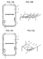
- the circulation path of the circulation air generated by the circulation-air generating unit is formed on a flat surface inside the cleaning tank 5, it is possible to arrange a plurality of grooves 23 formed in a square shape or in a curved surface along a direction of flow of the circulation air, on a surface 51 constituting the circulation path in the cleaning tank 5 as shown in Figs. 13A and 13B. It is preferable to arrange the groove 23 with a width smaller than a face size of the cleaning medium 4, so that the cleaning medium 4 hardly falls into the groove 23.
- a space is formed between the surface 51 of the cleaning tank 5 and the cleaning medium 4, so that contact resistance between the surface 51 and the cleaning medium 4 can be reduced.
- a height of the groove 23 is sufficient as long as air can pass through the groove 23. For example, if the height is set in a range between 0.1 millimeter (mm) and 1 mm, the groove 23 can be easily processed.
- the surface 51, on which the circulation path is formed in the cleaning tank 5, is acceptable to form on a concavely curved surface as shown in Figs. 13C and 13D.
- the surface 51 formed on the concavely curved surface it is possible to prevent dispersion of the circulation air. Accordingly, a large amount of the cleaning media 4 can be delivered, making it possible to disperse large amounts of the cleaning media 4 in the cleaning tank 5. As a result, cleaning efficiency can be improved.
- an air rectifying unit 24 that leads the cleaning medium 4 toward the cleaning-medium accelerating unit 7, on an upper surface or an upper portion of a side surface of the cleaning tank 5, where the circulation path is formed.
- the air rectifying unit 24 By arranging the air rectifying unit 24 on the circulation path, it is possible to disperse a large amount of the cleaning media 4 between the cleaning-medium accelerating unit 7 and the cleaning target object 2, resulting in improving cleaning efficiency.
- the air rectifying unit that leads the circulation air toward a path of blowing high-velocity air from the cleaning-medium accelerating unit, it is possible to assuredly cause the cleaning medium to collide with the cleaning target object even when the air flow speed for delivering the cleaning medium increases. Therefore, it is possible to reduce such a loss that the cleaning medium circulates without colliding with the cleaning target object. As a result, it is possible to effectively use the cleaning medium. Furthermore, it is possible to use kinetic energy delivered through the circulation path in addition to energy from the cleaning-medium accelerating unit to cause the cleaning medium to collide with the cleaning target object. Therefore, cleaning efficiency can be improved.
- Figs. 15A and 15B it is possible to arrange an inclined surface 52 including an opening portion on a bottom portion of the cleaning tank 5, without forming the cleaning tank in a rectangular shape. It is possible to arrange the cleaning-medium recycle unit 8 on the inclined surface 52, the circulation-air generating unit 6 on the lower portion of the inclined surface 52, and flows the circulation air along the inclined surface from the circulation-air generating unit 6. With such configuration, when the cleaning medium 4 falls on the separation member 81 of the cleaning-medium recycle unit 8 after removing the dust from the cleaning target object 2 by a collision with the cleaning target object 2, the cleaning medium 4 can be easily collected around the outlet opening 65 of the circulation-air generating unit 6.
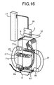
- the circulation-air generating unit 6 is singularly arranged in the cleaning tank 5.
- the circulation-air generating units 6a and 6b are arranged outside of the cleaning tank 5, the outlet opening 65 is arranged at the lower portion of the cleaning tank 5, and the inlet opening 61 is connected to an upper portion of the cleaning tank 5 via a duct hose 25.
- the controller 12 controls an operation of a circulation-switching control valve 26 that switches supply of compressed air to the circulation-air generating units 6a and 6b as shown in a block diagram of Fig. 18, in addition to the air-circulation solenoid valve 14, the acceleration solenoid valve 15, the acceleration-switching control valve 16, and the recycling solenoid valve 17 as shown in a block diagram of Fig. 17.
- the controller 12 controls the circulation-switching control valve 26 to alternately generate the circulation air from each of the circulation-air generating units 6a and 6b. Accordingly, the cleaning media 4 are hardly accumulated inside the cleaning tank 5. Therefore, it is possible to effectively use the cleaning medium 4 inside the cleaning tank 5, increasing possibility of collision between the cleaning medium 4 and the cleaning target object 2. As a result, cleaning efficiency can be improved.
- the inlet opening 61 is connected to the cleaning tank 5 via the duct hose 25, because the duct hose 25 is connected to the upper portion of the cleaning tank 5, where space density due to the cleaning medium 4 is small, it is possible to prevent the cleaning medium 4 from clogging the duct hose 25 or the circulation-air generating units 6a and 6b.
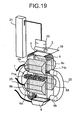
- the cleaning-medium recycle unit 8 is singularly arranged in the cleaning tank 5, it is possible to arrange a plurality of the cleaning-medium recycle units 8 in a third embodiment of the present invention.
- a plurality of cleaning-medium recycle units 8a to 8d which sandwich the arrayed acceleration nozzles 71a and 71b, in addition to the cleaning-medium recycle unit 8 arranged on the bottom portion of the cleaning tank 5.
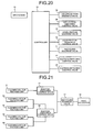
- the controller 12 controls operations of each of a suction-switching control valve 27 that switches a suction operation performed to the cleaning-medium recycle unit 8, and a suction-switching control valve 28 that switches a suction operation performed to each of the cleaning-medium recycle units 8a to 8d as shown in a block diagram of Fig. 21, in addition to the air-circulation solenoid valve 14, the acceleration solenoid valve 15, the acceleration-switching control valve 16, the recycling solenoid valve 17, and the circulation-switching control valve 26 as shown in a block diagram of Fig. 20. As shown in Fig.
- the controller 12 when cleaning the cleaning target object 2 by blowing compressed air from the acceleration nozzle 71a arranged on a front surface of the cleaning tank 5, the controller 12 connects the suction-switching control valve 28 to the cleaning-medium recycle unit 8, and connects the suction-switching control valve 28 to the cleaning-medium recycle units 8c and 8d arranged on a back surface of the cleaning tank 5.
- the controller 12 when cleaning the cleaning target object 2 by blowing compressed air from the acceleration nozzle 71b arranged on the back surface of the cleaning tank 5, the controller 12 connects the suction-switching control valve 28 to the cleaning-medium recycle units 8a and 8b arranged on the front surface of the cleaning tank 5.
- the dust 3 and the cleaning medium 4 flown up by the compressed air blown from the acceleration nozzle 71a are stuck to the cleaning-medium recycle units 8c and 8d.
- air-flow from the acceleration nozzle 71a acts on the dust 3 and the cleaning medium 4, in addition to suction air from the cleaning-medium recycle units 8c and 8d. Therefore, it is possible to largely increase flow speed at a mesh portion of the separation member 81 of each of the cleaning-medium recycle units 8c and 8d, improving performance of removing the dust 3 attached to the cleaning medium 4. As a result, the cleaning medium 4 can be assuredly recycled.
- the cleaning-medium recycle units 8c and 8d terminates a suction operation after a predetermined time elapsed. Therefore, it is possible to assuredly remove, from the cleaning-medium recycle units 8c and 8b, the cleaning medium stuck to the cleaning-medium recycle units 8c and 8b.
- the flaked-shaped cleaning medium 4 is introduced into the cleaning tank 5 and accumulated on the separation member 81 of the cleaning-medium recycle unit 8. Subsequently, the cleaning target object 2 held by the work holding unit 20 is loaded from the cleaning-target loading port 9 by the work moving unit 21, and set at an initial position. The cover 10 is closed to seal off the cleaning tank 5.
- the controller 12 Upon receiving a cleaning start signal by an operation of the driving unit 13, the controller 12 opens the acceleration solenoid valve 15 to switch the acceleration-switching control valve 16 at a predetermined interval, so that each of the acceleration nozzles 71a and 71b alternately blows compressed air.
- the controller 12 switches the acceleration-switching control valve 16 in synchronization with switching of blowing compressed air from each of the acceleration nozzles 71a and 71b, to switch adsorption performed by each pair of the cleaning-medium recycle units 8a, 8b, and 8c, 8d, arranged on surfaces facing each of the acceleration nozzles 71a and 71b.
- the cleaning-medium recycle units 8c and 8d arranged on the back surface of the cleaning tank 5 performs suction operation.
- the circulation-air generating unit 6 generates circulation air to deliver and flow up the cleaning medium 4 accumulated on the separation member 81 of the cleaning-medium recycle unit 8, and the cleaning target object 2 is cleaned using the flowing cleaning medium 4.
- each of the acceleration nozzles 71a and 71b alternately blows compressed air, so that the controller 12 switches the acceleration-switching control valve 16 in synchronization with switching of blowing compressed air from each of the acceleration nozzles 71a and 71b. Accordingly, suction performed by each pair of the cleaning-medium recycle units 8a, 8b, and 8c, 8d, which are arranged on surfaces respectively facing the acceleration nozzles 71a and 71b, can be switched from one another. Subsequently, the controller 12 shakes off the cleaning medium 4 attached by static electricity to the cleaning target object 2, and terminates a cleaning operation.
- the controller 12 opens the cover 10 of the cleaning tank 5 to take off the cleaning target object 2 from the cleaning tank 5 by the work moving unit 21, and replaces the cleaning target object with a new cleaning target object to restart the cleaning operation.
- the cleaning-medium recycle units 8a to 8d are arranged on the front and the back surfaces of the cleaning tank 5, it is possible to arrange differently.
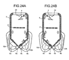
- inclined surfaces 52a and 52b including respective openings, which make V-shaped bottom portion of the cleaning tank 5, are arranged on a bottom portion of the cleaning tank 5
- the cleaning-medium recycle units 8 is arranged on each of the inclined surfaces 52a and 52b
- the circulation-air generating units 6a and 6b are arranged at respective lower end portions of the inclined surfaces 52a and 52b
- the air rectifying unit 24 that leads the cleaning medium 4 toward the cleaning-medium accelerating unit 7, on a top surface or a top portion of a side surface of the cleaning tank 5 constituting the circulation path of the circulation air.
- the circulation-air generating unit that generates circulation air along each of the inclined surfaces is arranged on the lower end portion of each of the inclined surfaces, and each of the circulation-air generating unit arranged on each of the lower end portions of the inclined surfaces are alternately operated, the cleaning medium can be collected at one area on the circulation path. Furthermore, the circulation air is intermittently generated along the internal surfaces of the cleaning tank to circulate the collected cleaning medium along the internal surfaces of the cleaning tank. Thus, it is possible to deliver a large amount of the cleaning media at one time with less amounts of air. As a result, energy saving can be realized and cleaning efficiency can be improved.
- the cleaning media 4 are flown up to clean the cleaning target object 2 by colliding with the cleaning target object 2, part of the cleaning media 4 are discharged to the dust collector 19 through the mesh portion included in the separation member 81 of the cleaning-medium recycle unit 8. Accordingly, the number of the cleaning media 4 in the cleaning tank 5 decreases during cleaning. When amount of the flowing cleaning medium 4 decreases in the cleaning tank 5 due to a decrease of the number of the cleaning media 4 in the cleaning tank 5, cleaning effect decreases. In some cases, a plurality of the cleaning target objects 2 held by the work holding unit 20 are loaded into the cleaning tank 5 for cleaning.
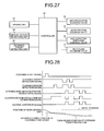
- the medium-amount measuring unit 29 is constituted of a photoelectronic sensor 291 arranged in such a manner that an optical axis of the photoelectronic sensor 291 becomes orthogonal to a direction of circulation of the cleaning medium 4 as shown in Fig. 26.
- the cleaning-target detecting units 30a and 30b are constituted of a photoelectronic sensor including a light projecting/receiving unit 301 and a reflecting plate 302.
- the light projecting/receiving unit 301 is attached to either the front surface or the back surface of the cleaning tank 5 via a transparent window for preventing interference with the cleaning medium 4.
- the reflecting plate 302 is attached to an internal surface that faces the light projecting/receiving unit 301, and arranged in such a manner that its optical axis crosses the cleaning tank 5 in a longitudinal direction.
- the medium-amount measuring unit 29, and the cleaning-target detecting units 30a, 30b are connected to the controller 12 as shown in Fig. 27.
- the controller 12 measures how many times the optical axis of the photoelectronic sensor 291 as the medium-amount measuring unit 29 is blocked, quantifies amounts of the flowing cleaning medium 4 during a predetermined time period, and controls the cleaning operation when one of the cleaning-target detecting units 30a and 30b detects the cleaning target object 2.
- the circulation-air generating unit 6 After a plurality of the cleaning target objects 2 held by the work holding unit 20 are loaded into the cleaning tank 5 as shown in Fig. 25, and when receiving a cleaning start signal, the circulation-air generating unit 6 generates circulation air for delivering the cleaning medium 4 accumulated on the cleaning-medium recycle unit 8 and flowing up the cleaning medium 4 inside the cleaning tank 5.
- the photoelectronic sensor 291 as the medium-amount measuring unit 29 detects the amount of the flowing cleaning medium 4 and inputs measured amount to the controller 12.
- the controller 12 compares input amount of the flowing cleaning medium 4 in a predetermined time period with a predetermined threshold. When the amount of the flowing cleaning medium 4 exceeds the threshold, the controller 12 starts a cleaning operation.
- the controller 12 When the amount of the flowing cleaning medium 4 is equal to or smaller the threshold, the controller 12 issues a warning indicating scarcity of the cleaning medium 4, and terminates the cleaning operation. Subsequently, when the cleaning medium 4 with a predetermined amount or an amount corresponding to the scarcity is supplied from a hopper or the like. When the cleaning medium 4 is flown up in response to the reception of the cleaning start signal, and the amount of the flowing cleaning medium 4 exceeds the threshold, the controller 12 restarts the cleaning operation.
- the controller 12 determines cleaning quality from the amount of the flowing cleaning medium 4 for each predetermined time period. Furthermore, it is possible to assuredly quantify the cleaning quality and cleaning performance by recording variation of the amount of the flowing cleaning medium 4.
- a plurality of the cleaning target objects 2 held by the work holding unit 20 is moved up and down by the work moving unit 21.
- the controller 12 determines a timing of performing an operation of blowing compressed air from the acceleration nozzle 71a and a suction operation by the cleaning-medium recycle unit 8.
- the timing is determined to include a delayed time taken by the cleaning target object 2 to reach a position of the acceleration nozzles 71a and 71b based on a moving speed of the cleaning target object 2 and a distance between the cleaning-target detecting unit 30a and the acceleration nozzles 71a and 71b. Subsequently, the controller 12 stops flowing circulation air at the timing, blows compressed air from the acceleration nozzle 71a, and cleans the first cleaning target object 2 by causing the cleaning-medium recycle unit 8 to start the suction operation.
- the controller 12 terminates the operation of blowing the compressed air from the acceleration nozzle 71a and the suction operation of the cleaning-medium recycle unit 8, at a timing including a delayed time taken by the cleaning target object 2 to reach a position of the acceleration nozzles 71a and 71b, which is obtained from a moving speed of the cleaning target object 2 and a distance between the cleaning-target detecting unit 30a and the acceleration nozzles 71a and 71b. Subsequently, the controller 12 causes the circulation-air generating unit 6 to generate circulation air.
- the controller 12 repeats the above control operation every time the cleaning-target detection signal is input from the cleaning-target detecting unit 30a, and sequentially cleans each of the cleaning target objects 2.
- the controller 12 repeats the above control operation every time the cleaning-target detection signal is input from the cleaning-target detecting unit 30b arranged under the acceleration nozzles 71a and 71b to blow compressed air from the acceleration nozzle 71b. Accordingly, the entire surfaces of the cleaning target objects 2 can be cleaned.
- the photoelectronic sensor 291 is used as the medium-amount measuring unit 29, it is possible to employ a method of accumulating impact force of the cleaning medium 4 to the cleaning target object 2 by a force sensor, weight measurement at a time of termination of a process by a weight sensor, or a method of measuring accumulation amount at a bottom portion of the cleaning tank 5 by a distance sensor or the like.
- a force sensor weight measurement at a time of termination of a process by a weight sensor
- a method of measuring accumulation amount at a bottom portion of the cleaning tank 5 by a distance sensor or the like.
- a work-position changing unit 31 that rotates the work holding unit 20 in a direction of rotation of an axis in a longitudinal direction by a motor or an air cylinder, between the work moving unit 21 and the work holding unit 20.
- the cleaning target object 2 held by the work holding unit 20 and loaded into the cleaning tank 5 is rotated by the work-position changing unit 31 to move up and down in the cleaning tank 5, and cleaned by alternately blowing compressed air from a plurality of pairs of the acceleration nozzles 71.
- the cleaning target object 2 is rotated when moving up and down, and compressed air is blown to the cleaning target object 2 from each different direction. Therefore, it is possible to assuredly clean an entire surface of the cleaning target object 2 even when the cleaning target object 2 is in a complicated shape.
- the circulation-air generating unit directly generates circulation air that flows along an internal surface of the cleaning tank, generated circulation air is applied to the cleaning medium from a direction orthogonal to a direction of a face of the cleaning medium accumulated in the cleaning tank, so that the cleaning medium is delivered and flown up. Accordingly, it is possible to apply effective force for flowing the accumulated cleaning medium by the circulation air, resulting in flowing large number of the cleaning media and increasing frequency of collision of the cleaning medium with the cleaning target object. As a result, it is possible to realize desired quality in cleaning.
- the cleaning-medium recycle unit removes attachment on the cleaning medium by suction. Therefore, cleanness of the cleaning medium can be maintained, maintaining desired quality in cleaning. Furthermore, the cleaning medium can be repeatedly used, realizing to perform a cleaning with low environmental burdens.
Abstract
Description
- The present application claims priority to and incorporates by reference the entire contents of
Japanese priority documents, 2006-240920 2006-240948 2006-240971 - The present invention generally relates to an image forming apparatus, and specifically relates to a technology for performing dry cleaning of components used in an image forming apparatus.
- Recently, manufactures of office equipments, such as copying machines, facsimile machines, and printers, have been proactively making recycling activities to create a resource recycling society. Such recycling activities include collecting used products from users, disassembling, cleaning, and reassembling the products, and reusing the products themselves or certain components of the products. In the case of image forming apparatuses, such as copying machines, facsimile machines, and printers, toner, which is a very fine powder, generally inevitably adheres to the components inside the image forming apparatuses. When recycling the image forming apparatuses itself or the components thereof, it is necessary to clean the toner.
- Some conventional methods, i.e., wet cleaning methods, use water or solvent for cleaning the toner. However, in such methods, there is a problem of increase of energy consumption, environmental burdens, and costs because of processes necessary for disposing effluent that contains toner and for drying the components after the cleaning is finished.
- Some other conventional methods, i.e., dry cleaning methods, use air blow for cleaning the toner. However, because cleaning performance is not sufficient for removing toner attached with strong adhesive force, an extra process is necessary for manually removing toner using a cloth or the like. Thus, the cleaning process is considered as one of bottleneck processes in a product reusing/recycling process.
- Some still other conventional methods, i.e., blast cleaning methods, use dry ice for the toner. However, these methods have higher running costs and they put a lot of burden on the environment because they use a large amount of dry ice.
- For counteracting above problems,
Japanese Patent No. 3288462 - Furthermore,
Japanese Patent No. 2889547 Japanese Patent No. 3468995 - Furthermore,
Japanese Patent Application Laid-Open No. 2005-329292 - However, in the dry cleaning device disclosed in the
Japanese Patent No. 3288462 - Furthermore, in the shot blast method disclosed in the
Japanese Patents No. 2889547 No. 3468995 - Moreover, in the dry cleaning device disclosed in the
Japanese Patent Application Laid-Open No. 2005-329292 - It is an object of the present invention to at least partially solve the problems in the conventional technology.
- According to an aspect of the present invention, there is provided a dry cleaning device including a circulation-air generating unit that generates high-velocity air inside a cleaning tank to flow up flexible flaked-shaped cleaning medium present in the cleaning tank; a cleaning-medium accelerating unit that accelerates the cleaning medium flowing in the cleaning tank so that the cleaning medium collides with a cleaning target object thereby separating particles sticking onto the cleaning target object; and a cleaning-medium recycle unit that sucks the particles separated from the cleaning target object and recycles the cleaning medium.
- According to another aspect of the present invention, there is provided a dry cleaning method including delivering a flaked-shaped flexible cleaning media accumulated on a surface of a cleaning tank, by circulation air flowing along surfaces of the cleaning tank; flowing up the flaked-shaped flexible cleaning media delivered at the delivering in the cleaning tank; causing the cleaning media flown at the flowing up to collide with a cleaning target object by high-velocity air; and removing particles sticking to the cleaning target object.
- The above and other objects, features, advantages and technical and industrial significance of this invention will be better understood by reading the following detailed description of presently preferred embodiments of the invention, when considered in connection with the accompanying drawings.
-
- Fig. 1 is a schematic diagram of a dry cleaning device according to a first embodiment of the present invention;
- Figs. 2A and 2B are schematic diagrams for explaining a process of removing dust from a cleaning target object shown in Fig. 1 by a flake-shaped cleaning medium;
- Figs. 3A and 3B are cross sections of a cleaning tank shown in Fig. 1;
- Fig. 4 is a cross section of a circulation-air generating unit shown in Fig. 1;
- Figs. 5A and 5B are schematic diagrams of a cleaning-medium recycle unit shown in Fig. 1;
- Fig. 6 is a block diagram of a drive control unit of the dry cleaning device shown in Fig. 1;
- Figs. 7A and 7B are block diagrams of a driving unit of the dry cleaning device shown in Fig. 1;
- Fig. 8 is a timechart of a cleaning operation performed by the dry cleaning device shown in Fig. 1;
- Figs. 9A to 9C are schematic diagrams for explaining a state of delivery, by circulation air, of cleaning media accumulated on the cleaning-medium recycle unit shown in Fig. 1;
- Figs. 10A to 10C are schematic diagrams for explaining another state of delivery, by circulation air, of cleaning media accumulated on the cleaning-medium recycle unit shown in Fig. 1;
- Figs. 11A to 11C are schematic diagrams for explaining a process of cleaning a cleaning target object shown in Fig. 1;
- Fig. 12 is a schematic diagram for explaining collision of a cleaning medium with a cleaning target object by air output from an acceleration nozzle of a cleaning-medium accelerating unit shown in Fig. 1;
- Figs. 13A to 13D are schematic diagrams of internal surfaces with circulation paths for circulating air in the cleaning tank shown in Fig. 1;
- Figs. 14A and 14B are cross sections of the cleaning tank with air rectifying unit on the circulation paths shown in Figs. 13A to 13D;
- Figs. 15A and 15B are cross sections of the cleaning tank with an inclined surface according to the first embodiment;
- Fig. 16 is a schematic diagram of a dry cleaning device according to a second embodiment of the present invention;
- Fig. 17 is a block diagram of a drive control unit of the dry cleaning device shown in Fig. 16;
- Fig. 18 is a block diagram of a driving unit of the dry cleaning device shown in Fig. 16;
- Fig. 19 is a schematic diagram of a dry cleaning device according to a third embodiment of the present invention;
- Fig. 20 is a block diagram of a drive control unit of the dry cleaning device shown in Fig. 19;
- Fig. 21 is a block diagram of a driving unit of the dry cleaning device shown in Fig. 19;
- Fig. 22 is a schematic diagram for explaining a state of colliding a cleaning medium with a cleaning target object in the dry cleaning device shown in Fig. 19;
- Fig. 23 is a timechart of a cleaning operation including a rough cleaning and a shake-off operation according to the third embodiment;
- Figs. 24A and 24B are schematic diagrams of a dry cleaning device according to a fourth embodiment of the present invention;
- Fig. 25 is a schematic diagram of a dry cleaning device including a medium-amount measuring unit and a cleaning-target detecting unit according to a fifth embodiment of the present invention;
- Fig. 26 is a schematic diagram of a photoelectronic sensor constituting the medium-amount measuring unit shown in Fig. 25;
- Fig. 27 is a block diagram of a drive control unit of the dry cleaning device shown in Fig. 25;
- Fig. 28 is a timechart of an operation performed by the dry cleaning device shown in Fig. 25; and
- Fig. 29 is a schematic diagram of a dry cleaning device according to a sixth embodiment of the present invention.
- Exemplary embodiments of the present invention are explained in detail below with reference to the accompanying drawings.
- Fig. 1 is a schematic diagram of a
dry cleaning device 1 according to a first embodiment of the present invention. Thedry cleaning device 1 removesvarious dusts 3, such as toner, attached to acleaning target object 2 by using a cleaningmedium 4 flown by high-velocity air as shown in Fig. 2. Thedry cleaning device 1 includes acleaning tank 5, a circulation-air generating unit 6, a cleaning-medium accelerating unit 7, and a cleaning-medium recycle unit 8. - The cleaning
medium 4 used in thedry cleaning device 1 can be formed in one of granular shape, stick shape, tubular shape, fibriform, flaked shape, and the like, which is made of one of metals, ceramics, synthetic resin, sponge, fabric, and the like. A shape and material of the cleaningmedium 4 can be determined depending on characteristics of a shape and material of thecleaning target object 2 or a particle size or attachment strength of thedust 3 attached to thecleaning target object 2. As for the cleaningmedium 4 in a flaked shape, a preferable size is such that its area is in a range between 1 square millimeter (mm2) and 1000 mm2, and its thickness is in a range between 1 micrometer (µm) and 500 µm. For example, for removing, from a component made of synthetic resin or metal, toner particle having an average diameter of 5 µm to 10 µm, which is used for an electrophotographic image forming apparatus, it is preferable to use the cleaningmedium 4 made of resin film, paper, or metal flake, in a flaked-shape. - When the cleaning
medium 4 is in a flaked shape, when the cleaningmedium 4 collides with thecleaning target object 2 at an edge portion of the cleaningmedium 4, contact force is concentrated on the edge portion, enabling the cleaningmedium 4 to obtain force necessary for removing thedust 3 even though mass of the cleaningmedium 4 is small. Because the cleaningmedium 4 gets bent and loses applied force when the contact force to thecleaning target object 2 increases, unwanted extra force is not applied to thecleaning target object 2. Accordingly, thecleaning target object 2 hardly gets damaged unlike a general blast shot material or an abrasive for barell finishing. Furthermore, inelastic collision occurs between the flaked-shapedcleaning medium 4 and thecleaning target object 2 largely due to viscous drag of air applied when the cleaningmedium 4 is bent caused by collision with thecleaning target object 2. Therefore, the cleaningmedium 4 is hardly bounced. When oblique collision occurs between the cleaningmedium 4 and thecleaning target object 2, the cleaningmedium 4 slides across a surface of thecleaning target object 2, contacting a wide area of the surface by a single collision. Due to scratching action or scrubbing action caused by the contact, a parallel force is applied to a contact surface of thedust 3 attached to thecleaning target object 2. As a result, it is possible to remove thedust 3 from thecleaning target object 2 with small force, increasing cleaning efficiency. - The
cleaning tank 5 is formed in substantially rectangular solid with a hollow body, and includes a cleaning-target loading port 9 on its top surface for loading thecleaning target object 2, an opening portion on its bottom portion, acover 10, which can be flexibly opened and closed, on the cleaning-target loading port 9, and the cleaning-medium recycle unit 8 at an opening portion of its bottom portion. On a portion of an internal surface of one side surface of thecleaning tank 5, the circulation-air generating unit 6 is arranged as shown in Fig. 3, forming a circulation path of circulation air on internal surfaces of both side surfaces, the bottom surface, and the top surface of thecleaning tank 5. Each of corner portions of the internal surfaces constituting the circulation path is formed in R shape as shown in Fig. 3A, or with a predetermined angle θ between each of the side surfaces, the top surface, and the bottom surface as shown in Fig. 3B, so that circulation air can be effectively circulated. The predetermined angle θ is preferably determined between 120° and 150° for circulating the circulation air with less resistance. - As described above, each of the corner portions of the internal surfaces with the circulation path is formed in a circular shape or with a predetermined angle between each of adjacent side surfaces. Therefore, the cleaning medium can be delivered without colliding with the internal surfaces. As a result, it is possible to effectively deliver the cleaning medium, increasing cleaning efficiency, and to deliver the cleaning medium with less air supplied, realizing energy saving.
- The circulation-
air generating unit 6 includes aninlet portion 62 having aninlet opening 61 with a large diameter, and anoutlet portion 64 having a compressed-air supply opening 63 arranged on a periphery of an outlet side of theinlet portion 62. The circulation-air generating unit 6 inlets air from theinlet portion 62 by high-velocity airflow supplied from the compressed-air supply opening 63 generated toward anoutlet opening 65 of theoutlet portion 64, and outlets air with amount of several times to dozens of times of amount of compressed air supplied from the compressed-air supply opening 63. By using the circulation-air generating unit 6, it is possible to circulate the cleaning medium with less energy, reducing amount of the compressed air to be consumed, compared to a case using a general air-blow nozzle. Furthermore, it is possible to easily maintain negative pressure inside thecleaning tank 5 and to prevent leakage of the dusts outside thecleaning tank 5. Various gasses, such as nitride gas, carbon dioxide gas, inactive gas including argon gas, instead of the compressed air, can be supplied from the compressed-air supply opening 63. In the embodiments described below, cases employing the compressed air are explained. The circulation-air generating unit 6 is arranged on a side surface constituting the circulation path near the bottom portion of thecleaning tank 5, with the inlet opening 61 side up while the outlet opening 65 side down. - The cleaning-
medium accelerating unit 7 includes a plurality ofacceleration nozzles 71a arrayed on a front surface orthogonal to an internal surface constituting the circulation path, and a plurality ofacceleration nozzles 71b arrayed on a back surface facing the front surface with theacceleration nozzles 71a arranged. The cleaning-medium accelerating unit 7 blowouts compressed air supplied from a compressed-air source, such as a compressor and a compression tank, inside thecleaning tank 5 via each of theacceleration nozzles medium 4 to collide with thecleaning target object 2. It is preferable to use a blowout nozzle, like the circulation-air generating unit 6, for theacceleration nozzles - With the cleaning-
medium accelerating unit 7 arranged on a surface orthogonal to the surface constituting the circulation path of the circulation air inside the cleaning tank, and with the nozzle of the cleaning-medium accelerating unit 7 embedded inside the surface of the cleaning tank, it is possible to avoid interference in circulation of the circulation air and effectively cause the cleaning medium to collide with the cleaning target object. - The cleaning-
medium recycle unit 8 includes aseparation member 81 and ahood 82 arranged on an internal surface of the bottom portion of thecleaning tank 5, forming a closed space as shown in a perspective view of Fig. 5A and a partial cross section of Fig. 5B. The closed space is connected to a dust collector (not shown) including a negative-pressure generating source via asuction tube 11, such as a hose, to generate negative pressure in thehood 82. Theseparation member 81 includes a plurality of small poles and slits 83 in a size through which air and particles can pass while the cleaningmedium 4 cannot pass, and are made of porous member, such as metal, plastic mesh, mesh, punched metal plate, and slit plate. With this configuration, theseparation member 81 removes dust removed from thecleaning target object 2, and eliminates the cleaningmedium 4 worn and chipped by collision with thecleaning target object 2, or the cleaningmedium 4 with degraded elasticity due to long-term use. - As described above, dust and the like attached to the cleaning medium is removed by adsorption by the cleaning-medium recycle unit, so that it is possible to maintain a cleanness of the cleaning medium. Therefore, it is possible to maintain high quality in cleaning, and the cleaning medium can be used repeatedly, resulting in realizing a cleaning with low environmental burdens.
- By arranging the cleaning-medium recycle unit at the bottom portion of the cleaning tank, it is possible to increase possibility that the cleaning medium, which has been fallen down the bottom portion of the cleaning tank by gravitation, passes through the cleaning-medium recycle unit, increasing efficiency of recycling the cleaning medium. As a result, the cleanness of the cleaning medium can be improved, improving quality in cleaning.
- A
controller 12 of thedry cleaning device 1 includes an air-circulation solenoid valve 14, anacceleration solenoid valve 15, an acceleration-switchingcontrol valve 16, and arecycling solenoid valve 17, which are connected to thecontroller 12 with one another, and controls each of the solenoid valves by a drive signal from a drivingunit 13, as shown in a block diagram of Fig. 6 and pipeline diagrams shown in Figs. 7A and 7B. The air-circulation solenoid valve 14 performs conduction and non-conduction of an air pipe for supplying compressed air from a compressed-air supplying device 18 to the circulation-air generating unit 6. Theacceleration solenoid valve 15 performs conduction and non-conduction of an air pipe for supplying compressed air to the cleaning-medium accelerating unit 7. The acceleration-switchingcontrol valve 16 switches directions of flow of compressed air to be supplied to theacceleration nozzles medium accelerating unit 7. Therecycling solenoid valve 17 performs conduction and non-conduction of thesuction tube 11 connecting the cleaning-medium recycle unit 8 to adust collector 19. - An operation is explained below with reference to a timechart shown in Fig. 8, of removing the
dust 3 attached to thecleaning target object 2 by loading thecleaning target object 2 held by awork holding unit 20 into thecleaning tank 5 by awork moving unit 21 in thedry cleaning device 1. - The flaked-shaped
cleaning medium 4 is introduced into thecleaning tank 5 and accumulated on theseparation member 81 of the cleaning-medium recycle unit 8. Subsequently, thecleaning target object 2 held by thework holding unit 20 is loaded from the cleaning-target loading port 9 by thework moving unit 21 and set at an initial position. Thecover 10 is closed to seal off thecleaning tank 5. Upon receiving a cleaning start signal by an operation of the drivingunit 13, thecontroller 12 opens the air-circulation solenoid valve 14 and supplies compressed air to the circulation-air generating unit 6 from the compressed-air supplying device 18, such as a compressor, so that the circulation-air generating unit 6 generates circulation air that flows along the circulation path arranged on the internal surfaces of thecleaning tank 5. The circulation air flows along theseparation member 81, so that the circulation air acts on the flaked-shapedcleaning medium 4 accumulated on theseparation member 81 from a longitudinal direction as shown in Fig. 9A, and gradually chips away accumulation of the cleaning medium 4 from an upper portion of the accumulation. As a result, the cleaningmedium 4 is delivered and flown up in thecleaning tank 5 as shown in Figs. 9B and 9C. Because the circulation air for flowing up the cleaningmedium 4 is directly blown from the circulation-air generating unit 6 into thecleaning tank 5, large impact force can be applied to the accumulated cleaningmedium 4. Therefore, it is possible to assuredly flow up the accumulated cleaningmedium 4 by the circulation air. - As descried above, the circulation-air generating unit generates the circulation air that flows along the surface of the cleaning medium accumulated on the cleaning-medium recycle unit. Therefore, it is possible to apply large force for flowing up the accumulated cleaning medium to a large amount of the cleaning media, and circulate the cleaning medium along the internal surfaces of the cleaning tank. As a result, cleaning efficiency can be improved.
- In other words, by flowing the circulation air generated by the circulation-air generating unit along the cleaning-medium recycle unit, it is possible to assuredly remove, from the cleaning-medium recycle unit, the cleaning medium stuck to the cleaning-medium recycle unit, and deliver the cleaning medium in the cleaning tank. Furthermore, it is possible to maintain performance of the cleaning-medium recycle unit, of recycling the cleaning medium.
- Moreover, by generating the circulation air from the circulation-air generating unit along the longitudinal direction of the cleaning tank, the circulation air is not dispersed and its force is not lost upon flowing. Therefore, it is possible to effectively apply the force of the circulation air to the cleaning medium accumulated on the bottom portion of the cleaning tank. Furthermore, it is possible to deliver and flow up the cleaning medium even with small number of the circulation-air generating units and small amount of air supplied to the circulation-air generating unit. As a result, it is possible to suppress amount of energy necessary for cleaning.
- For delivering and flowing up the accumulated flaked-shaped
cleaning medium 4 by air as described above, when the air is applied in a direction orthogonal to a longitudinal direction of the accumulated cleaningmedium 4 by anozzle 22 to the flaked-shapedcleaning medium 4 accumulated on theseparation member 81 as shown in Fig. 10A, it is necessary to supply compressed air with energy sufficient for flowing up entire portion of the cleaningmedium 4 where the compressed air is applied. Accordingly, as shown in Fig. 10B, it becomes difficult to flow the cleaningmedium 4 as accumulation amount of the cleaningmedium 4 increases. In addition, although it is possible to flow up the cleaningmedium 4 accumulated on a portion right over thenozzle 22 that outputs air, because flowability of the accumulated flaked-shapedcleaning medium 4 is low, it is difficult to flow up entire portion of the accumulated cleaning medium 4 even when theseparation member 81 is inclined toward thenozzle 22 as shown in Fig. 10C. As a result, the cleaning medium accumulated on a portion around thenozzle 22 is left without being flown up. On the contrary, when air is applied from a longitudinal direction of the cleaningmedium 4 accumulated on theseparation member 81 by generating, by the circulation-air generating unit 6, circulation air that flows along the circulation path on the internal surface of thecleaning tank 5, it is possible to assuredly flow up the cleaningmedium 4 with less energy. As a result, it is possible to reduce consumption of the amount of compressed air supplied to the circulation-air generating unit 6. If the cleaningmedium 4 is delivered by air using a duct or a hose, the cleaningmedium 4 may be clogged in the duct or the hose. However, the circulation path of the circulation air is formed on the internal surfaces of thecleaning tank 5 in the first embodiment, it is possible to avoid clogging the cleaningmedium 4 in the circulation path, resulting in flowing up the cleaningmedium 4 in thecleaning tank 5. - According to the embodiments, circulation air for delivering and flowing up the flaked-shaped flexible cleaning medium flows along the internal surfaces of the cleaning tank, so that the circulation air is not dispersed and its force is not lost. Therefore, it is possible to effectively apply force of the circulation air to the cleaning medium accumulated on the cleaning tank, delivering and flowing up a large amount of the cleaning media with less amount of air supplied. As a result, energy consumption necessary for cleaning can be suppressed. Furthermore, even when once-removed dust is re-attached to the internal surfaces of the cleaning tank, the internal surfaces can be continuously cleaned because a large amount of the cleaning media is circulating. Therefore, it is possible to reduce operations in maintenance, such as cleaning, of the cleaning tank.
- The circulation-
air generating unit 6 that generates circulation air is arranged with the inlet opening 61 side up and the outlet opening 65 side down, around the bottom portion of a side surface constituting the circulation path in thecleaning tank 5. Therefore, it is possible to apply air with strong force to the cleaningmedium 4 accumulated on theseparation member 81 on the bottom portion of thecleaning tank 5, along a bottom surface of thecleaning tank 5. As a result, it is possible to deliver the cleaningmedium 4 along the internal surfaces of thecleaning tank 5 to an area away from theoutlet opening 65. In addition, the cleaningmedia 4 introduced into theinlet opening 61 are dispersed, reducing space density. Therefore, the cleaningmedium 4 hardly clogs theinlet opening 61, resulting in stably generating the circulation air. In other words, when theinlet opening 61 is arranged around the bottom portion of the cleaning tank with its opening side down, the force of suction air is exclusively applied to the cleaningmedium 4 around theinlet opening 61. Therefore, it is difficult to deliver large amounts of the cleaningmedia 4 accumulated on the bottom portion of thecleaning tank 5. In addition, when large amounts of the accumulatedcleaning media 4 are adsorbed by theinlet opening 61, space density in the inlet opening 61 increases by the cleaningmedia 4. Therefore, theinlet opening 61 is clogged. However, with the configuration described in the first embodiment, it is possible to avoid such problems. - The
controller 12 closes the air-circulation solenoid valve 14 when a predetermined time elapsed, and causes the circulation-air generating unit 6 to stop generating the circulation air. Subsequently, thecontroller 12 causes thework moving unit 21 to move down thecleaning target object 2 from the initial position, opens theacceleration solenoid valve 15 to supply compressed air to the cleaning-medium accelerating unit 7 via the acceleration-switchingcontrol valve 16, so that compressed air is blown out from theacceleration nozzle 71a of the cleaning-medium accelerating unit 7. Thecontroller 12 opens therecycling solenoid valve 17 to conduct the cleaning-medium recycle unit 8 to thedust collector 19, and generates negative pressure in thehood 82. When the circulation air generated by the circulation-air generating unit 6 is stopped, the cleaningmedium 4 flown by the circulation air is fallen down. The falling down cleaningmedium 4 is caused to collide with thecleaning target object 2 by the compressed air blown from theacceleration nozzle 71a, removing thedust 3 attached to a surface of thecleaning target object 2. - The
dust 3 removed from thecleaning target object 2 and the cleaningmedium 4 with the dust attached due to collision with thecleaning target object 2 are fallen by gravity, and accumulated on theseparation member 81 of the cleaning-medium recycle unit 8 that is vacuuming air due to the negative pressure inside thehood 82. The dust fallen on theseparation member 81 and the dust attached to the cleaningmedium 4 are vacuumed into thehood 82 due to the negative pressure inside thehood 82, and collected by thedust collector 19. As a result, the cleaningmedium 4 with the dust attached can be effectively recycled. - Upon blowing compressed air from the
acceleration nozzle 71a for a predetermined time period, thecontroller 12 closes theacceleration solenoid valve 15 and therecycling solenoid valve 17, and stops operations of the cleaning-medium accelerating unit 7 and the cleaning-medium recycle unit 8. When therecycling solenoid valve 17 is closed, the negative pressure inside thehood 82 is released, so that vacuum force of thehood 82 to the cleaningmedium 4 accumulated on theseparation member 81 is lost. Therefore, the cleaningmedium 4 is removed from theseparation member 81 by subsequent flow of the circulation air. Accordingly, the dust can be continuously removed from the cleaningmedium 4 without causing the cleaningmedium 4 to cover and seal a mesh portion of theseparation member 81. Therefore, it is not required to replace all the cleaningmedia 4, making it possible to effectively use the cleaningmedium 4 by supplying deficient amounts due to damage. As a result, maintenance efficiency can be improved. - As described above, by intermittently operating the cleaning-medium recycle unit, it is possible to remove, from the cleaning-medium recycle unit, the cleaning medium stuck to the cleaning-medium recycle unit. Therefore, performance of the cleaning-medium recycle unit can be maintained.
- It is difficult for the cleaning medium to move when the cleaning-medium recycle unit is vacuuming the cleaning medium for recycling because retaining force is applied to the cleaning medium. However, because the cleaning medium is not recycled during circulation of the cleaning medium according to the first embodiment, it is possible to realize effective circulation of the cleaning medium. As a result, it is possible to load a large number of the cleaning media to the cleaning-medium accelerating unit, improving cleaning efficiency.
- The
controller 12 re-opens the air-circulation solenoid valve 14 to cause the circulation-air generating unit 6 to generate circulation air, flows the cleaningmedium 4 recycled and accumulated on theseparation member 81 of the cleaning-medium recycle unit 8 for a predetermined time period T1. Subsequently, thecontroller 12 opens theacceleration solenoid valve 15 and therecycling solenoid valve 17 to switch the acceleration-switchingcontrol valve 16 to theacceleration nozzle 71b, and performs a process of removing dust from thecleaning target object 2 and a process of recycling the cleaningmedium 4 for a predetermined time period. The time for performing the processes of removing dust from thecleaning target object 2 and recycling the cleaningmedium 4 are set longer than a time for generating the circulation air, so that wide range of thecleaning target object 2 can be cleaned. Because compressed air is blown out alternately from each of theacceleration nozzles acceleration nozzles medium 4 to collide with thecleaning target object 2. As a result, cleaning efficiency of the cleaningmedium 4 can be improved. - The processes of generating the circulation air, removing dust from the
cleaning target object 2, and recycling the cleaningmedium 4 are repeatedly performed while thecleaning target object 2 gradually moves down from the initial position. As shown in Fig. 11B, when thecleaning target object 2 reaches a turn-round position, thework moving unit 21 stops moving down thecleaning target object 2, and gradually moves up thecleaning target object 2. Thecontroller 12 alternately performs each of the processes of generating the circulation air, removing dust from thecleaning target object 2, and recycling the cleaningmedium 4 when thecleaning target object 2 is gradually moving up, removing thedust 3 from an entire surface of thecleaning target object 2. As shown in Fig. 11C, when thecleaning target object 2 reaches an upper end portion of thecleaning tank 5, i.e., the initial position, thecontroller 12 stops a cleaning operation. When the cleaning operation is stopped, thecontroller 12 opens thecover 10 of thecleaning tank 5 to discharge thecleaning target object 2 held by thework holding unit 20 from thecleaning tank 5 using thework moving unit 21. Subsequently, thecleaning target object 2 is replaced with new cleaning target object and the cleaning operation is restarted. - As described above, by intermittently operating the cleaning-medium circulating unit and the cleaning-medium accelerating unit or the cleaning-medium recycle unit, it is possible to avoid interference between each of operations of accelerating, vacuuming, and circulating the cleaning medium. Therefore, it is possible to effectively move the cleaning medium, and cause the cleaning medium to collide with the cleaning target object. As a result, cleaning performance can be improved and energy consumption can be reduced.
- Although it is explained that the compressed air is alternately blown out from each of the
acceleration nozzles medium accelerating unit 7 to clean an entire surface of thecleaning target object 2, it is possible to simultaneously blow out compressed air from each of theacceleration nozzles cleaning target object 2, it is sufficient to blow compressed air from one of theacceleration nozzles - By arranging the cleaning-medium accelerating unit in such a manner that generated air and circulation air generated by the circulation-air generating unit do not flow in the same plane, avoiding interference between the circulation air and the air for accelerating the cleaning medium. As a result, it is possible to realize stable cleaning performance.
- Furthermore, although it is explained that the circulation path of the circulation air generated by the circulation-air generating unit is formed on a flat surface inside the
cleaning tank 5, it is possible to arrange a plurality ofgrooves 23 formed in a square shape or in a curved surface along a direction of flow of the circulation air, on asurface 51 constituting the circulation path in thecleaning tank 5 as shown in Figs. 13A and 13B. It is preferable to arrange thegroove 23 with a width smaller than a face size of the cleaningmedium 4, so that the cleaningmedium 4 hardly falls into thegroove 23. By arranging thegroove 23 as described above, a space is formed between thesurface 51 of thecleaning tank 5 and the cleaningmedium 4, so that contact resistance between thesurface 51 and the cleaningmedium 4 can be reduced. Furthermore, by flowing the circulation air in thegroove 23, it is possible to effectively deliver the cleaningmedium 4, realizing delivery of large amounts of the cleaningmedia 4. Moreover, because circulation air is rectified by a plurality of thegrooves 23, occurrence of turbulence can be avoided, preventing degradation of air force. Therefore, it is possible to effectively deliver and flow up the cleaningmedium 4, resulting in improving cleaning efficiency. A height of thegroove 23 is sufficient as long as air can pass through thegroove 23. For example, if the height is set in a range between 0.1 millimeter (mm) and 1 mm, thegroove 23 can be easily processed. - It is acceptable to form the
surface 51, on which the circulation path is formed in thecleaning tank 5, on a concavely curved surface as shown in Figs. 13C and 13D. With thesurface 51 formed on the concavely curved surface, it is possible to prevent dispersion of the circulation air. Accordingly, a large amount of the cleaningmedia 4 can be delivered, making it possible to disperse large amounts of the cleaningmedia 4 in thecleaning tank 5. As a result, cleaning efficiency can be improved. - As shown in Figs. 14A and 14B, it is preferable to arrange an
air rectifying unit 24 that leads the cleaningmedium 4 toward the cleaning-medium accelerating unit 7, on an upper surface or an upper portion of a side surface of thecleaning tank 5, where the circulation path is formed. By arranging theair rectifying unit 24 on the circulation path, it is possible to disperse a large amount of the cleaningmedia 4 between the cleaning-medium accelerating unit 7 and thecleaning target object 2, resulting in improving cleaning efficiency. Furthermore, it is possible to directly cause the cleaningmedium 4, of which flowing direction is changed by theair rectifying unit 24, to collide with thecleaning target object 2 to perform cleaning. It is preferable to adjust an angle of flowing air by theair rectifying unit 24 depending on a shape or a position of thecleaning target object 2. - As described above, by arranging, in the cleaning tank, the air rectifying unit that leads the circulation air toward a path of blowing high-velocity air from the cleaning-medium accelerating unit, it is possible to assuredly cause the cleaning medium to collide with the cleaning target object even when the air flow speed for delivering the cleaning medium increases. Therefore, it is possible to reduce such a loss that the cleaning medium circulates without colliding with the cleaning target object. As a result, it is possible to effectively use the cleaning medium. Furthermore, it is possible to use kinetic energy delivered through the circulation path in addition to energy from the cleaning-medium accelerating unit to cause the cleaning medium to collide with the cleaning target object. Therefore, cleaning efficiency can be improved.
- As shown in Figs. 15A and 15B, it is possible to arrange an
inclined surface 52 including an opening portion on a bottom portion of thecleaning tank 5, without forming the cleaning tank in a rectangular shape. It is possible to arrange the cleaning-medium recycle unit 8 on theinclined surface 52, the circulation-air generating unit 6 on the lower portion of theinclined surface 52, and flows the circulation air along the inclined surface from the circulation-air generating unit 6. With such configuration, when the cleaningmedium 4 falls on theseparation member 81 of the cleaning-medium recycle unit 8 after removing the dust from thecleaning target object 2 by a collision with thecleaning target object 2, the cleaningmedium 4 can be easily collected around the outlet opening 65 of the circulation-air generating unit 6. By generating the circulation air from the circulation-air generating unit 6 to the collected cleaningmedium 4, it is possible to deliver a large number of the cleaningmedia 4 by less amount of compressed air, realizing energy saving. Furthermore, by using the area where the cleaning-medium recycle unit 8 is arranged as an area for collecting the cleaningmedium 4, it is possible to take longer time for recycling the cleaningmedium 4. As a result, efficiency of recycling the cleaningmedium 4 can be improved. - It is explained in the first embodiment that the circulation-
air generating unit 6 is singularly arranged in thecleaning tank 5. However, in a second embodiment of the present invention, it is possible to symmetrically arrange two circulation-air generating units cleaning tank 5, in such a manner that the circulation-air generating units separation member 81 of the cleaning-medium recycle unit 8. In the example shown in Fig. 16, the circulation-air generating units cleaning tank 5, theoutlet opening 65 is arranged at the lower portion of thecleaning tank 5, and theinlet opening 61 is connected to an upper portion of thecleaning tank 5 via aduct hose 25. In this case, thecontroller 12 controls an operation of a circulation-switchingcontrol valve 26 that switches supply of compressed air to the circulation-air generating units circulation solenoid valve 14, theacceleration solenoid valve 15, the acceleration-switchingcontrol valve 16, and therecycling solenoid valve 17 as shown in a block diagram of Fig. 17. When flowing the cleaningmedium 4 by generating the circulation air inside thecleaning tank 5, thecontroller 12 controls the circulation-switchingcontrol valve 26 to alternately generate the circulation air from each of the circulation-air generating units media 4 are hardly accumulated inside thecleaning tank 5. Therefore, it is possible to effectively use the cleaningmedium 4 inside thecleaning tank 5, increasing possibility of collision between the cleaningmedium 4 and thecleaning target object 2. As a result, cleaning efficiency can be improved. - By connecting the inlet opening 61 to the upper portion of the
cleaning tank 5 via theduct hose 25, it is possible to generate ascending air current inside thecleaning tank 5. Therefore, floating duration of the cleaningmedium 4 can be increased, increasing the number of the flowingcleaning medium 4. As a result, it is possible to increase the number of the cleaningmedia 4 that collide with thecleaning target object 2 by compressed air blown out from theacceleration nozzles inlet opening 61 is connected to thecleaning tank 5 via theduct hose 25, because theduct hose 25 is connected to the upper portion of thecleaning tank 5, where space density due to the cleaningmedium 4 is small, it is possible to prevent the cleaning medium 4 from clogging theduct hose 25 or the circulation-air generating units - Although it is explained that the cleaning-
medium recycle unit 8 is singularly arranged in thecleaning tank 5, it is possible to arrange a plurality of the cleaning-medium recycle units 8 in a third embodiment of the present invention. For example, as shown in Fig. 19, it is possible to arrange a plurality of cleaning-medium recycle units 8a to 8d, which sandwich the arrayedacceleration nozzles medium recycle unit 8 arranged on the bottom portion of thecleaning tank 5. In this case, thecontroller 12 controls operations of each of a suction-switchingcontrol valve 27 that switches a suction operation performed to the cleaning-medium recycle unit 8, and a suction-switchingcontrol valve 28 that switches a suction operation performed to each of the cleaning-medium recycle units 8a to 8d as shown in a block diagram of Fig. 21, in addition to the air-circulation solenoid valve 14, theacceleration solenoid valve 15, the acceleration-switchingcontrol valve 16, therecycling solenoid valve 17, and the circulation-switchingcontrol valve 26 as shown in a block diagram of Fig. 20. As shown in Fig. 22, when cleaning thecleaning target object 2 by blowing compressed air from theacceleration nozzle 71a arranged on a front surface of thecleaning tank 5, thecontroller 12 connects the suction-switchingcontrol valve 28 to the cleaning-medium recycle unit 8, and connects the suction-switchingcontrol valve 28 to the cleaning-medium recycle units cleaning tank 5. On the other hand, when cleaning thecleaning target object 2 by blowing compressed air from theacceleration nozzle 71b arranged on the back surface of thecleaning tank 5, thecontroller 12 connects the suction-switchingcontrol valve 28 to the cleaning-medium recycle units cleaning tank 5. In this manner, thedust 3 and the cleaningmedium 4 flown up by the compressed air blown from theacceleration nozzle 71a are stuck to the cleaning-medium recycle units dust 3 and the cleaningmedium 4 are stuck to the cleaning-medium recycle units acceleration nozzle 71a acts on thedust 3 and the cleaningmedium 4, in addition to suction air from the cleaning-medium recycle units separation member 81 of each of the cleaning-medium recycle units dust 3 attached to the cleaningmedium 4. As a result, the cleaningmedium 4 can be assuredly recycled. When blowing of the compressed air from theacceleration nozzle 71a is stopped, the cleaning-medium recycle units medium recycle units medium recycle units - As described above, by alternately switching an operation of recycling the cleaning medium performed by each of the cleaning-medium recycle units, action for sucking the cleaning medium is continuously performed in one of the cleaning-medium recycle units in the cleaning tank. As a result, it is possible to maintain recyclability of the cleaning medium and negative pressure inside the cleaning tank.
- It is possible to prevent unwanted situation in which the flown cleaning medium 4 falls down without being accelerated by the
acceleration nozzles media 4 between theacceleration nozzles cleaning target object 2 when theacceleration nozzles cleaning target object 2 by colliding the flaked-shapedcleaning target 4 with thecleaning target object 2, quality in cleaning is substantially proportional to frequency of collision of the cleaningmedium 4 with thecleaning target object 2 at a predetermined speed or faster. Therefore, if supply amount of the cleaningmedia 4 increases, quality in cleaning is improved, resulting in reducing cleaning time and energy consumption. - It is possible to clean the
cleaning target object 2 using the cleaningmedium 4 after performing rough cleaning using theacceleration nozzles medium recycle units 8a to 8b. An operation of performing the rough cleaning is explained with reference to a timechart shown in Fig. 23. - The flaked-shaped
cleaning medium 4 is introduced into thecleaning tank 5 and accumulated on theseparation member 81 of the cleaning-medium recycle unit 8. Subsequently, thecleaning target object 2 held by thework holding unit 20 is loaded from the cleaning-target loading port 9 by thework moving unit 21, and set at an initial position. Thecover 10 is closed to seal off thecleaning tank 5. Upon receiving a cleaning start signal by an operation of the drivingunit 13, thecontroller 12 opens theacceleration solenoid valve 15 to switch the acceleration-switchingcontrol valve 16 at a predetermined interval, so that each of theacceleration nozzles controller 12 switches the acceleration-switchingcontrol valve 16 in synchronization with switching of blowing compressed air from each of theacceleration nozzles medium recycle units acceleration nozzles acceleration nozzle 71a arranged on the front surface of thecleaning tank 5 blows compressed air, the cleaning-medium recycle units cleaning tank 5 performs suction operation. With this operation, the compressed air blown out from theacceleration nozzle 71a collides with thecleaning target object 2, so that a large part of thedust 3 or weakly-attached stain on thecleaning target object 2 are removed, completing rough cleaning of thecleaning target object 2. Subsequently, the circulation-air generating unit 6 generates circulation air to deliver and flow up the cleaningmedium 4 accumulated on theseparation member 81 of the cleaning-medium recycle unit 8, and thecleaning target object 2 is cleaned using the flowingcleaning medium 4. After the cleaning by the flowingcleaning medium 4 is finished, each of theacceleration nozzles controller 12 switches the acceleration-switchingcontrol valve 16 in synchronization with switching of blowing compressed air from each of theacceleration nozzles medium recycle units acceleration nozzles controller 12 shakes off the cleaningmedium 4 attached by static electricity to thecleaning target object 2, and terminates a cleaning operation. Thereafter, thecontroller 12 opens thecover 10 of thecleaning tank 5 to take off thecleaning target object 2 from thecleaning tank 5 by thework moving unit 21, and replaces the cleaning target object with a new cleaning target object to restart the cleaning operation. By performing shake off cleaning of the cleaningmedium 4 as described above, it is possible to increase cleaning speed and improve cleaning quality. - Although it is explained that the cleaning-
medium recycle units 8a to 8d are arranged on the front and the back surfaces of thecleaning tank 5, it is possible to arrange differently. In a forth embodiment of the present invention, as shown in Figs. 24A and 24B,inclined surfaces cleaning tank 5, are arranged on a bottom portion of thecleaning tank 5, the cleaning-medium recycle units 8 is arranged on each of theinclined surfaces air generating units inclined surfaces air generating units inclined surfaces air rectifying unit 24 that leads the cleaningmedium 4 toward the cleaning-medium accelerating unit 7, on a top surface or a top portion of a side surface of thecleaning tank 5 constituting the circulation path of the circulation air. - As described above, with a configuration in which a V-shaped inclined surfaces including the cleaning-medium recycle unit are arranged at the bottom portion of the cleaning tank, the circulation-air generating unit that generates circulation air along each of the inclined surfaces is arranged on the lower end portion of each of the inclined surfaces, and each of the circulation-air generating unit arranged on each of the lower end portions of the inclined surfaces are alternately operated, the cleaning medium can be collected at one area on the circulation path. Furthermore, the circulation air is intermittently generated along the internal surfaces of the cleaning tank to circulate the collected cleaning medium along the internal surfaces of the cleaning tank. Thus, it is possible to deliver a large amount of the cleaning media at one time with less amounts of air. As a result, energy saving can be realized and cleaning efficiency can be improved.
- When the cleaning
media 4 are flown up to clean thecleaning target object 2 by colliding with thecleaning target object 2, part of the cleaningmedia 4 are discharged to thedust collector 19 through the mesh portion included in theseparation member 81 of the cleaning-medium recycle unit 8. Accordingly, the number of the cleaningmedia 4 in thecleaning tank 5 decreases during cleaning. When amount of the flowing cleaning medium 4 decreases in thecleaning tank 5 due to a decrease of the number of the cleaningmedia 4 in thecleaning tank 5, cleaning effect decreases. In some cases, a plurality of the cleaningtarget objects 2 held by thework holding unit 20 are loaded into thecleaning tank 5 for cleaning. In this case, it is preferable to arrange a medium-amount measuring unit 29 inside thecleaning tank 5, and arrange cleaning-target detecting units acceleration nozzles amount measuring unit 29 is constituted of aphotoelectronic sensor 291 arranged in such a manner that an optical axis of thephotoelectronic sensor 291 becomes orthogonal to a direction of circulation of the cleaningmedium 4 as shown in Fig. 26. The cleaning-target detecting units unit 301 and a reflectingplate 302. The light projecting/receivingunit 301 is attached to either the front surface or the back surface of thecleaning tank 5 via a transparent window for preventing interference with the cleaningmedium 4. The reflectingplate 302 is attached to an internal surface that faces the light projecting/receivingunit 301, and arranged in such a manner that its optical axis crosses thecleaning tank 5 in a longitudinal direction. The medium-amount measuring unit 29, and the cleaning-target detecting units controller 12 as shown in Fig. 27. Thecontroller 12 measures how many times the optical axis of thephotoelectronic sensor 291 as the medium-amount measuring unit 29 is blocked, quantifies amounts of the flowing cleaning medium 4 during a predetermined time period, and controls the cleaning operation when one of the cleaning-target detecting units cleaning target object 2. - The cleaning operation performed by a cleaning device in which the medium-
amount measuring unit 29, and the cleaning-target detecting units cleaning tank 5 is described with reference to a timechart shown in Fig. 28. - After a plurality of the cleaning
target objects 2 held by thework holding unit 20 are loaded into thecleaning tank 5 as shown in Fig. 25, and when receiving a cleaning start signal, the circulation-air generating unit 6 generates circulation air for delivering the cleaningmedium 4 accumulated on the cleaning-medium recycle unit 8 and flowing up the cleaningmedium 4 inside thecleaning tank 5. Thephotoelectronic sensor 291 as the medium-amount measuring unit 29 detects the amount of the flowingcleaning medium 4 and inputs measured amount to thecontroller 12. Thecontroller 12 compares input amount of the flowing cleaning medium 4 in a predetermined time period with a predetermined threshold. When the amount of the flowingcleaning medium 4 exceeds the threshold, thecontroller 12 starts a cleaning operation. When the amount of the flowingcleaning medium 4 is equal to or smaller the threshold, thecontroller 12 issues a warning indicating scarcity of the cleaningmedium 4, and terminates the cleaning operation. Subsequently, when the cleaningmedium 4 with a predetermined amount or an amount corresponding to the scarcity is supplied from a hopper or the like. When the cleaningmedium 4 is flown up in response to the reception of the cleaning start signal, and the amount of the flowingcleaning medium 4 exceeds the threshold, thecontroller 12 restarts the cleaning operation. - As described above, because the amount of the flowing
cleaning medium 4 is detected and cleaning is performed using the cleaningmedium 4 with a predetermined amount or larger, it is possible to perform cleaning in desired quality. The amount of the cleaningmedium 4 that collides with thecleaning target object 2 is proportional to the amount of the flowingcleaning medium 4. Therefore, it is possible for thecontroller 12 to determine cleaning quality from the amount of the flowingcleaning medium 4 for each predetermined time period. Furthermore, it is possible to assuredly quantify the cleaning quality and cleaning performance by recording variation of the amount of the flowingcleaning medium 4. - Upon starting a cleaning operation, a plurality of the cleaning
target objects 2 held by thework holding unit 20 is moved up and down by thework moving unit 21. When the firstcleaning target object 2 reaches a position where the optical axis of a cleaning-target detecting unit 29a arranged on theacceleration nozzles cleaning target object 2, and a cleaning-target detection signal is input from the cleaning-target detecting unit 29a to thecontroller 12, thecontroller 12 determines a timing of performing an operation of blowing compressed air from theacceleration nozzle 71a and a suction operation by the cleaning-medium recycle unit 8. The timing is determined to include a delayed time taken by thecleaning target object 2 to reach a position of theacceleration nozzles cleaning target object 2 and a distance between the cleaning-target detecting unit 30a and theacceleration nozzles controller 12 stops flowing circulation air at the timing, blows compressed air from theacceleration nozzle 71a, and cleans the firstcleaning target object 2 by causing the cleaning-medium recycle unit 8 to start the suction operation. When input of the cleaning-target detection signal from the cleaning-target detecting unit 30a is stopped, thecontroller 12 terminates the operation of blowing the compressed air from theacceleration nozzle 71a and the suction operation of the cleaning-medium recycle unit 8, at a timing including a delayed time taken by thecleaning target object 2 to reach a position of theacceleration nozzles cleaning target object 2 and a distance between the cleaning-target detecting unit 30a and theacceleration nozzles controller 12 causes the circulation-air generating unit 6 to generate circulation air. Thecontroller 12 repeats the above control operation every time the cleaning-target detection signal is input from the cleaning-target detecting unit 30a, and sequentially cleans each of the cleaning target objects 2. When thecleaning target object 2 reaches a turn-round position and starts moving up, thecontroller 12 repeats the above control operation every time the cleaning-target detection signal is input from the cleaning-target detecting unit 30b arranged under theacceleration nozzles acceleration nozzle 71b. Accordingly, the entire surfaces of the cleaningtarget objects 2 can be cleaned. - As described above, because compressed air is blown from the
acceleration nozzles cleaning target object 2, it is possible to reduce usage of the compressed air, realizing energy consumption. - Although it is explained that the
photoelectronic sensor 291 is used as the medium-amount measuring unit 29, it is possible to employ a method of accumulating impact force of the cleaningmedium 4 to thecleaning target object 2 by a force sensor, weight measurement at a time of termination of a process by a weight sensor, or a method of measuring accumulation amount at a bottom portion of thecleaning tank 5 by a distance sensor or the like. When accumulating the impact force of the cleaningmedium 4, it is possible to determine a cleaning quality from the number of accumulated impact. - In a sixth embodiment of the present invention shown in Fig. 29, it is possible to include a work-
position changing unit 31 that rotates thework holding unit 20 in a direction of rotation of an axis in a longitudinal direction by a motor or an air cylinder, between thework moving unit 21 and thework holding unit 20. In addition, it is possible to arrange a plurality of pairs, e.g., three pairs, of the arrayedacceleration nozzles 71 as the cleaning-medium accelerating unit 7 on a side surface of thecleaning tank 5, which constitutes circulation path, in such a manner that a direction of blow of air from each of theacceleration nozzle 71 differs from one another, e.g., horizontal direction and vertical direction. Thecleaning target object 2 held by thework holding unit 20 and loaded into thecleaning tank 5 is rotated by the work-position changing unit 31 to move up and down in thecleaning tank 5, and cleaned by alternately blowing compressed air from a plurality of pairs of theacceleration nozzles 71. As described above, thecleaning target object 2 is rotated when moving up and down, and compressed air is blown to thecleaning target object 2 from each different direction. Therefore, it is possible to assuredly clean an entire surface of thecleaning target object 2 even when thecleaning target object 2 is in a complicated shape. - According to an aspect of the present invention, the circulation-air generating unit directly generates circulation air that flows along an internal surface of the cleaning tank, generated circulation air is applied to the cleaning medium from a direction orthogonal to a direction of a face of the cleaning medium accumulated in the cleaning tank, so that the cleaning medium is delivered and flown up. Accordingly, it is possible to apply effective force for flowing the accumulated cleaning medium by the circulation air, resulting in flowing large number of the cleaning media and increasing frequency of collision of the cleaning medium with the cleaning target object. As a result, it is possible to realize desired quality in cleaning.
- According to another aspect of the present invention, the cleaning-medium recycle unit removes attachment on the cleaning medium by suction. Therefore, cleanness of the cleaning medium can be maintained, maintaining desired quality in cleaning. Furthermore, the cleaning medium can be repeatedly used, realizing to perform a cleaning with low environmental burdens.
- Although the invention has been described with respect to specific embodiments for a complete and clear disclosure, the appended claims are not to be thus limited but are to be construed as embodying all modifications and alternative constructions that may occur to one skilled in the art that fairly fall within the basic teaching herein set forth.
Claims (22)
- A dry cleaning device comprising:a circulation-air generating unit (6) that generates high-velocity air inside a cleaning tank (5) to flow up flexible flaked-shaped cleaning medium (4) present in the cleaning tank (5);a cleaning-medium accelerating unit (7) that accelerates the cleaning medium (4) flowing in the cleaning tank (5) so that the cleaning medium (4) collides with a cleaning target object thereby separating particles sticking onto the cleaning target object; anda cleaning-medium recycle unit (8) that sucks the particles separated from the cleaning target object and recycles the cleaning medium (4).
- The dry cleaning device according to claim 1, wherein the circulation-air generating unit (6) generates circulation air that flows along an inner surface of the cleaning tank (5).
- The dry cleaning device according to claim 1 or 2, wherein the circulation-air generating unit (6) generates circulation air that flows along the cleaning-medium recycle unit (8).
- The dry cleaning device according to claim 1 or 2, wherein the circulation-air generating unit (6) generates circulation air that flows along a longitudinal direction of the cleaning tank (5).
- The dry cleaning device according to claim 1 or 2, wherein the circulation-air generating unit (6) includes
a cylindrical inlet member (62) having a first inlet opening (61) and a first outlet opening, the first inlet opening (61) being larger in size than the first outlet opening, and the first outlet opening being larger in size than the cleaning medium (4); and
a cylindrical outlet member (64) having a second inlet opening, an air inlet opening (63), and a second outlet opening (65), the second inlet opening being larger in size than the first outlet opening and arranged around the first outlet opening, and the air inlet opening (63) being arranged near the second inlet opening, wherein
high-velocity air is passed into the cylindrical outlet member (64) from the air inlet opening (63) whereby the cleaning medium (4) enters into the cylindrical inlet member (62) from the first inlet opening (61), then enters into the cylindrical outlet member (64) from the first outlet opening and the second inlet opening, and finally goes out of the cylindrical outlet member (64) from the second outlet opening (65). - The dry cleaning device according to claim 5, wherein the first inlet opening (61) is arranged at a higher position than a position of the outlet opening in the cleaning tank (5).
- The dry cleaning device according to claim 1 or 2, wherein the circulation-air generating unit (6) is provided in plurality, and
the dry cleaning device further comprising a controller (12) that switches an operation of generating circulation air for each of the circulation-air generating units (6). - The dry cleaning device according to claim 1 or 2, further comprising a controller (12) that intermittently drives at least two from among the circulation-air generating unit (6), the cleaning-medium accelerating unit (7), and the cleaning-medium recycle unit (8).
- The dry cleaning device according to claim 1 or 2, wherein the cleaning-medium accelerating unit (7) is arranged on a surface of the cleaning tank (5), the surface being a surface orthogonal to another surface on which a circulation path is arranged, the circulation path along which the circulation air flows.
- The dry cleaning device according to claim 1 or 2, wherein the cleaning-medium accelerating unit (7) includes a nozzle embedded in a surface of the cleaning tank (5).
- The dry cleaning device according to claim 1 or 2, wherein the cleaning-medium recycle unit (8) is arranged on a bottom portion of the cleaning tank (5).
- The dry cleaning device according to claim 1 or 2, wherein the cleaning-medium recycle unit (8) is provided in plurality, and the cleaning-medium recycle units (8) are arranged on a bottom portion of the cleaning tank (5) at positions facing the cleaning-medium accelerating unit (7).
- The dry cleaning device according to claim 12, further comprising a controller (12) that alternately switches operations of recycling the cleaning medium (4) respectively performed by the cleaning-medium recycle units (8).
- The dry cleaning device according to claim 1 or 2, wherein a plurality of grooves (23) are arranged on a surface of the cleaning tank (5) along a direction of flow of the circulation air, the surface being a surface along which the circulation air flows.
- The dry cleaning device according to claim 1 or 2, wherein a curved surface in concaved shaped is arranged on a surface of the cleaning tank (5) along a direction of flow of the circulation air, the surface being a surface along which the circulation air flows.
- The dry cleaning device according to claim 1 or 2, further comprising an inclined surface (52) arranged on a bottom portion of the cleaning tank (5), wherein
the cleaning-medium recycle unit (8) is arranged on the inclined surface (52), and
the circulation-air generating unit (6) generates circulation air that flows along the inclined surface (52) and is arranged on a lower end portion of the inclined surface (52). - The dry cleaning device according to claim 1 or 2, further comprising a V-shaped inclined surface (52a) arranged inside the cleaning tank (5) on a bottom portion of the cleaning tank (5), wherein
the cleaning-medium recycle unit (8) is arranged on each of side surfaces of the V-shaped inclined surface (52a), and
the circulation-air generating unit (6) generates circulation air that flows along each of the side surfaces of the V-shaped inclined surface (52a) and is arranged on a lower end portion of each of the side surfaces of the V-shaped inclined surface (52a). - The dry cleaning device according to claim 1 or 2, further comprising an air rectifying unit (24) arranged in the cleaning tank (5), wherein the air rectifying unit (24) leads the circulation air to a path of blowing high-velocity air from the cleaning-medium accelerating unit (7).
- The dry cleaning device according to claim 1 or 2, further comprising:a medium-amount measuring unit (29) that detects amount of the cleaning media flowing in the cleaning tank (5); anda controller (12) that compares the flowing amount measured by the medium-amount measuring unit (29) with a predetermined threshold, and when the flowing amount is equal to or lower than the threshold, issues a warning.
- The dry cleaning device according to claim 1 or 2, further comprising:a cleaning-target detecting unit (30a) that detects the cleaning target object in the cleaning tank (5), and outputs a signal indicative of a detection of the cleaning target object; anda controller (12) that operates the circulation-air generating unit (6), the cleaning-medium accelerating unit (7), and the cleaning-medium recycle unit (8) in synchronization with the signal.
- A dry cleaning method comprising:delivering a flaked-shaped flexible cleaning media accumulated on a surface of a cleaning tank, by circulation air flowing along surfaces of the cleaning tank);flowing up the flaked-shaped flexible cleaning media delivered at the delivering in the cleaning tank;causing the cleaning media flown at the flowing up to collide with a cleaning target object by high-velocity air; andremoving particles sticking to the cleaning target object.
- The dry cleaning method according to claim 21, further comprising cleaning particles attached to the cleaning medium after the cleaning medium collides with the cleaning target object, wherein the cleaning medium is repeatedly used after the particles are cleaned off at the cleaning.
Applications Claiming Priority (3)
| Application Number | Priority Date | Filing Date | Title |
|---|---|---|---|
| JP2006240920A JP4749287B2 (en) | 2006-09-06 | 2006-09-06 | Cleaning device |
| JP2006240948A JP4772624B2 (en) | 2006-09-06 | 2006-09-06 | Cleaning device |
| JP2006240971A JP4741998B2 (en) | 2006-09-06 | 2006-09-06 | Cleaning device and cleaning method |
Publications (3)
| Publication Number | Publication Date |
|---|---|
| EP1897628A2 true EP1897628A2 (en) | 2008-03-12 |
| EP1897628A3 EP1897628A3 (en) | 2012-03-14 |
| EP1897628B1 EP1897628B1 (en) | 2016-02-24 |
Family
ID=38792518
Family Applications (1)
| Application Number | Title | Priority Date | Filing Date |
|---|---|---|---|
| EP07253501.6A Expired - Fee Related EP1897628B1 (en) | 2006-09-06 | 2007-09-04 | Dry cleaning device |
Country Status (4)
| Country | Link |
|---|---|
| US (1) | US7730896B2 (en) |
| EP (1) | EP1897628B1 (en) |
| KR (1) | KR100890983B1 (en) |
| CN (1) | CN101254502B (en) |
Cited By (2)
| Publication number | Priority date | Publication date | Assignee | Title |
|---|---|---|---|---|
| EP2135687A1 (en) | 2008-06-18 | 2009-12-23 | Ricoh Company, Ltd. | Cleaning apparatus and cleaning method |
| US10772352B2 (en) | 2014-10-29 | 2020-09-15 | Altria Client Services Llc | Ethanol-free gel formulation cartridge for e-vaping device |
Families Citing this family (16)
| Publication number | Priority date | Publication date | Assignee | Title |
|---|---|---|---|---|
| US20040259750A1 (en) * | 2002-04-22 | 2004-12-23 | The Procter & Gamble Company | Processes and apparatuses for applying a benefit composition to one or more fabric articles during a fabric enhancement operation |
| JP4531841B2 (en) * | 2008-02-27 | 2010-08-25 | 株式会社リコー | Cleaning device and cleaning method |
| JP4758497B2 (en) * | 2008-07-10 | 2011-08-31 | 株式会社リコー | Cleaning device and cleaning method |
| CN102548673A (en) * | 2009-10-02 | 2012-07-04 | 夏普株式会社 | Cleaning nozzle and dust removal device equipped with same |
| JP5589356B2 (en) * | 2009-11-11 | 2014-09-17 | 株式会社リコー | Dry cleaning method and apparatus |
| JP5793980B2 (en) | 2010-11-10 | 2015-10-14 | 株式会社リコー | Dry cleaning housing and dry cleaning device |
| JP5712826B2 (en) | 2010-11-17 | 2015-05-07 | 株式会社リコー | Dry cleaning housing and dry cleaning device |
| JP5879903B2 (en) | 2011-02-25 | 2016-03-08 | 株式会社リコー | Dry cleaning housing, dry cleaning device and dry cleaning system |
| JP5953975B2 (en) | 2011-10-26 | 2016-07-20 | 株式会社リコー | Cleaning medium splash prevention member, cleaning object holder and dry cleaning device |
| JP5919786B2 (en) | 2011-12-12 | 2016-05-18 | 株式会社リコー | Dry cleaning housing and dry cleaning device |
| JP6492429B2 (en) | 2013-10-15 | 2019-04-03 | 株式会社リコー | Dry cleaning housing, dry cleaning device, and separation plate mounting method |
| JP2016067991A (en) * | 2014-09-29 | 2016-05-09 | 株式会社リコー | Cleaning medium suction unit and dry cleaning apparatus |
| KR20160065226A (en) * | 2014-11-07 | 2016-06-09 | 세메스 주식회사 | Apparatus and method for treating a subtrate |
| CN106695576B (en) * | 2017-03-17 | 2023-08-15 | 河南理工大学 | Pre-mixing type pulse abrasive gas jet erosion method and device |
| CN107901277B (en) * | 2017-12-27 | 2019-09-06 | 台州金福桂再生资源利用有限公司 | A kind of bending waste plastic scrapes equipment |
| CN113814226B (en) * | 2020-06-19 | 2023-01-24 | 理光高科技(深圳)有限公司 | Dry type cleaning device |
Citations (3)
| Publication number | Priority date | Publication date | Assignee | Title |
|---|---|---|---|---|
| JPH0379982B2 (en) | 1987-01-30 | 1991-12-20 | Q P Corp | |
| US6034351A (en) | 1998-06-24 | 2000-03-07 | Sato; Katsuhiro | Cleaning apparatus for welding torch nozzle and method of cleaning the same |
| JP2005329292A (en) | 2004-05-18 | 2005-12-02 | Ricoh Co Ltd | Dry type washing method and apparatus |
Family Cites Families (15)
| Publication number | Priority date | Publication date | Assignee | Title |
|---|---|---|---|---|
| US2440656A (en) * | 1946-03-18 | 1948-04-27 | Fred W Huntington | Abrasive material for polishing |
| JPH0718646B2 (en) * | 1989-08-22 | 1995-03-06 | ジャパン・フィールド株式会社 | Equipment for drying objects to be cleaned |
| JPH04256477A (en) * | 1991-02-07 | 1992-09-11 | Hoya Corp | Method and device for cleaning |
| CN2111375U (en) * | 1991-04-14 | 1992-07-29 | 邓志忠 | Automatic aspirating air filter |
| JP3288462B2 (en) | 1993-03-01 | 2002-06-04 | シシド静電気株式会社 | Static eliminator |
| JP3468995B2 (en) | 1996-07-30 | 2003-11-25 | 澁谷工業株式会社 | Method and apparatus for cleaning resin container |
| JP2889547B2 (en) | 1997-01-28 | 1999-05-10 | 日本カル株式会社 | Apparatus and method for collecting and treating surface deposits |
| EP1034733A1 (en) * | 1999-03-05 | 2000-09-13 | S.I.EL S.r.l. | Cleaning apparatus |
| CN2443788Y (en) * | 2000-09-22 | 2001-08-22 | 浙江大学 | Dry ice cleaning machine |
| JP4187636B2 (en) | 2003-12-10 | 2008-11-26 | 株式会社リコー | Toner container dry cleaning method and cleaning apparatus |
| JP2005182168A (en) | 2003-12-16 | 2005-07-07 | Sharp Corp | Content processor, content processing method, content processing program and recording medium |
| JP2005296853A (en) * | 2004-04-13 | 2005-10-27 | Ricoh Co Ltd | Fine powder removal apparatus |
| JP4318179B2 (en) | 2004-12-13 | 2009-08-19 | 国立大学法人 香川大学 | Novel disaccharide compound containing D-psicose and process for producing the same |
| WO2006075791A1 (en) | 2005-01-13 | 2006-07-20 | Matsushita Electric Industrial Co., Ltd. | Dry washing device |
| JP4580916B2 (en) | 2005-11-02 | 2010-11-17 | 株式会社リコー | Cleaning device and cleaning method |
-
2007
- 2007-08-29 US US11/896,019 patent/US7730896B2/en not_active Expired - Fee Related
- 2007-09-04 EP EP07253501.6A patent/EP1897628B1/en not_active Expired - Fee Related
- 2007-09-05 KR KR1020070089964A patent/KR100890983B1/en not_active IP Right Cessation
- 2007-09-06 CN CN200710164876XA patent/CN101254502B/en not_active Expired - Fee Related
Patent Citations (3)
| Publication number | Priority date | Publication date | Assignee | Title |
|---|---|---|---|---|
| JPH0379982B2 (en) | 1987-01-30 | 1991-12-20 | Q P Corp | |
| US6034351A (en) | 1998-06-24 | 2000-03-07 | Sato; Katsuhiro | Cleaning apparatus for welding torch nozzle and method of cleaning the same |
| JP2005329292A (en) | 2004-05-18 | 2005-12-02 | Ricoh Co Ltd | Dry type washing method and apparatus |
Cited By (3)
| Publication number | Priority date | Publication date | Assignee | Title |
|---|---|---|---|---|
| EP2135687A1 (en) | 2008-06-18 | 2009-12-23 | Ricoh Company, Ltd. | Cleaning apparatus and cleaning method |
| US8584312B2 (en) | 2008-06-18 | 2013-11-19 | Ricoh Company, Ltd. | Cleaning apparatus and cleaning method |
| US10772352B2 (en) | 2014-10-29 | 2020-09-15 | Altria Client Services Llc | Ethanol-free gel formulation cartridge for e-vaping device |
Also Published As
| Publication number | Publication date |
|---|---|
| KR100890983B1 (en) | 2009-03-27 |
| US7730896B2 (en) | 2010-06-08 |
| EP1897628B1 (en) | 2016-02-24 |
| US20080052953A1 (en) | 2008-03-06 |
| EP1897628A3 (en) | 2012-03-14 |
| CN101254502A (en) | 2008-09-03 |
| CN101254502B (en) | 2012-10-10 |
| KR20080022522A (en) | 2008-03-11 |
Similar Documents
| Publication | Publication Date | Title |
|---|---|---|
| US7730896B2 (en) | Dry cleaning device and dry cleaning method | |
| KR101025180B1 (en) | Cleaning medium and dry cleaning apparatus using the same | |
| US7865997B2 (en) | Dry type cleaning apparatus and dry type cleaning method | |
| JP4598694B2 (en) | Cleaning device and cleaning method | |
| JP4898939B2 (en) | Dry cleaning equipment | |
| JP5061053B2 (en) | Dry cleaning apparatus, dry cleaning method, cleaning product cleaned by the dry cleaning apparatus, and method of manufacturing the regenerator | |
| JP5101873B2 (en) | Cleaning medium | |
| JP4950329B2 (en) | Cleaning device | |
| JP4741998B2 (en) | Cleaning device and cleaning method | |
| JP2010279949A5 (en) | ||
| JP4772624B2 (en) | Cleaning device | |
| JP2007330947A (en) | Dry cleaning apparatus and method | |
| JP4954030B2 (en) | Cleaning medium and dry cleaning apparatus using the same | |
| JP4933374B2 (en) | Dry cleaning equipment | |
| JP5298681B2 (en) | Dry cleaning equipment | |
| JP5310812B2 (en) | Cleaning medium and dry cleaning apparatus using the same | |
| JP4902399B2 (en) | Dry cleaning equipment | |
| JP4749287B2 (en) | Cleaning device | |
| JP5218615B2 (en) | Dry cleaning equipment |
Legal Events
| Date | Code | Title | Description |
|---|---|---|---|
| PUAI | Public reference made under article 153(3) epc to a published international application that has entered the european phase |
Free format text: ORIGINAL CODE: 0009012 |
|
| 17P | Request for examination filed |
Effective date: 20070911 |
|
| AK | Designated contracting states |
Kind code of ref document: A2 Designated state(s): AT BE BG CH CY CZ DE DK EE ES FI FR GB GR HU IE IS IT LI LT LU LV MC MT NL PL PT RO SE SI SK TR |
|
| AX | Request for extension of the european patent |
Extension state: AL BA HR MK YU |
|
| PUAL | Search report despatched |
Free format text: ORIGINAL CODE: 0009013 |
|
| AK | Designated contracting states |
Kind code of ref document: A3 Designated state(s): AT BE BG CH CY CZ DE DK EE ES FI FR GB GR HU IE IS IT LI LT LU LV MC MT NL PL PT RO SE SI SK TR |
|
| AX | Request for extension of the european patent |
Extension state: AL BA HR MK RS |
|
| RIC1 | Information provided on ipc code assigned before grant |
Ipc: B24C 9/00 20060101ALI20120206BHEP Ipc: B24C 7/00 20060101ALI20120206BHEP Ipc: B08B 7/02 20060101AFI20120206BHEP |
|
| AKX | Designation fees paid |
Designated state(s): DE FR GB IT NL |
|
| GRAP | Despatch of communication of intention to grant a patent |
Free format text: ORIGINAL CODE: EPIDOSNIGR1 |
|
| RIC1 | Information provided on ipc code assigned before grant |
Ipc: B08B 7/02 20060101AFI20150811BHEP Ipc: B24C 5/00 20060101ALI20150811BHEP Ipc: B24C 7/00 20060101ALI20150811BHEP Ipc: B24C 9/00 20060101ALI20150811BHEP |
|
| INTG | Intention to grant announced |
Effective date: 20150903 |
|
| GRAS | Grant fee paid |
Free format text: ORIGINAL CODE: EPIDOSNIGR3 |
|
| GRAA | (expected) grant |
Free format text: ORIGINAL CODE: 0009210 |
|
| AK | Designated contracting states |
Kind code of ref document: B1 Designated state(s): DE FR GB IT NL |
|
| REG | Reference to a national code |
Ref country code: GB Ref legal event code: FG4D |
|
| REG | Reference to a national code |
Ref country code: DE Ref legal event code: R096 Ref document number: 602007044954 Country of ref document: DE |
|
| REG | Reference to a national code |
Ref country code: NL Ref legal event code: FP |
|
| PG25 | Lapsed in a contracting state [announced via postgrant information from national office to epo] |
Ref country code: IT Free format text: LAPSE BECAUSE OF FAILURE TO SUBMIT A TRANSLATION OF THE DESCRIPTION OR TO PAY THE FEE WITHIN THE PRESCRIBED TIME-LIMIT Effective date: 20160224 |
|
| REG | Reference to a national code |
Ref country code: DE Ref legal event code: R097 Ref document number: 602007044954 Country of ref document: DE |
|
| PLBE | No opposition filed within time limit |
Free format text: ORIGINAL CODE: 0009261 |
|
| STAA | Information on the status of an ep patent application or granted ep patent |
Free format text: STATUS: NO OPPOSITION FILED WITHIN TIME LIMIT |
|
| 26N | No opposition filed |
Effective date: 20161125 |
|
| REG | Reference to a national code |
Ref country code: DE Ref legal event code: R119 Ref document number: 602007044954 Country of ref document: DE |
|
| REG | Reference to a national code |
Ref country code: NL Ref legal event code: MM Effective date: 20161001 |
|
| GBPC | Gb: european patent ceased through non-payment of renewal fee |
Effective date: 20160904 |
|
| PG25 | Lapsed in a contracting state [announced via postgrant information from national office to epo] |
Ref country code: NL Free format text: LAPSE BECAUSE OF NON-PAYMENT OF DUE FEES Effective date: 20161001 |
|
| REG | Reference to a national code |
Ref country code: FR Ref legal event code: ST Effective date: 20170531 |
|
| PG25 | Lapsed in a contracting state [announced via postgrant information from national office to epo] |
Ref country code: DE Free format text: LAPSE BECAUSE OF NON-PAYMENT OF DUE FEES Effective date: 20170401 Ref country code: FR Free format text: LAPSE BECAUSE OF NON-PAYMENT OF DUE FEES Effective date: 20160930 Ref country code: GB Free format text: LAPSE BECAUSE OF NON-PAYMENT OF DUE FEES Effective date: 20160904 |