EP1782895B1 - Dry type cleaning apparatus and dry type cleaning method - Google Patents
Dry type cleaning apparatus and dry type cleaning method Download PDFInfo
- Publication number
- EP1782895B1 EP1782895B1 EP06255629A EP06255629A EP1782895B1 EP 1782895 B1 EP1782895 B1 EP 1782895B1 EP 06255629 A EP06255629 A EP 06255629A EP 06255629 A EP06255629 A EP 06255629A EP 1782895 B1 EP1782895 B1 EP 1782895B1
- Authority
- EP
- European Patent Office
- Prior art keywords
- cleaning
- unit
- medium
- tank
- dry type
- Prior art date
- Legal status (The legal status is an assumption and is not a legal conclusion. Google has not performed a legal analysis and makes no representation as to the accuracy of the status listed.)
- Expired - Fee Related
Links
Images


Classifications
-
- B—PERFORMING OPERATIONS; TRANSPORTING
- B24—GRINDING; POLISHING
- B24C—ABRASIVE OR RELATED BLASTING WITH PARTICULATE MATERIAL
- B24C3/00—Abrasive blasting machines or devices; Plants
- B24C3/18—Abrasive blasting machines or devices; Plants essentially provided with means for moving workpieces into different working positions
- B24C3/26—Abrasive blasting machines or devices; Plants essentially provided with means for moving workpieces into different working positions the work being supported by barrel cages, i.e. tumblers; Gimbal mountings therefor
-
- B—PERFORMING OPERATIONS; TRANSPORTING
- B08—CLEANING
- B08B—CLEANING IN GENERAL; PREVENTION OF FOULING IN GENERAL
- B08B5/00—Cleaning by methods involving the use of air flow or gas flow
-
- B—PERFORMING OPERATIONS; TRANSPORTING
- B08—CLEANING
- B08B—CLEANING IN GENERAL; PREVENTION OF FOULING IN GENERAL
- B08B5/00—Cleaning by methods involving the use of air flow or gas flow
- B08B5/02—Cleaning by the force of jets, e.g. blowing-out cavities
-
- B—PERFORMING OPERATIONS; TRANSPORTING
- B08—CLEANING
- B08B—CLEANING IN GENERAL; PREVENTION OF FOULING IN GENERAL
- B08B7/00—Cleaning by methods not provided for in a single other subclass or a single group in this subclass
- B08B7/02—Cleaning by methods not provided for in a single other subclass or a single group in this subclass by distortion, beating, or vibration of the surface to be cleaned
-
- B—PERFORMING OPERATIONS; TRANSPORTING
- B24—GRINDING; POLISHING
- B24B—MACHINES, DEVICES, OR PROCESSES FOR GRINDING OR POLISHING; DRESSING OR CONDITIONING OF ABRADING SURFACES; FEEDING OF GRINDING, POLISHING, OR LAPPING AGENTS
- B24B31/00—Machines or devices designed for polishing or abrading surfaces on work by means of tumbling apparatus or other apparatus in which the work and/or the abrasive material is loose; Accessories therefor
- B24B31/003—Machines or devices designed for polishing or abrading surfaces on work by means of tumbling apparatus or other apparatus in which the work and/or the abrasive material is loose; Accessories therefor whereby the workpieces are mounted on a holder and are immersed in the abrasive material
-
- B—PERFORMING OPERATIONS; TRANSPORTING
- B24—GRINDING; POLISHING
- B24B—MACHINES, DEVICES, OR PROCESSES FOR GRINDING OR POLISHING; DRESSING OR CONDITIONING OF ABRADING SURFACES; FEEDING OF GRINDING, POLISHING, OR LAPPING AGENTS
- B24B31/00—Machines or devices designed for polishing or abrading surfaces on work by means of tumbling apparatus or other apparatus in which the work and/or the abrasive material is loose; Accessories therefor
- B24B31/10—Machines or devices designed for polishing or abrading surfaces on work by means of tumbling apparatus or other apparatus in which the work and/or the abrasive material is loose; Accessories therefor involving other means for tumbling of work
- B24B31/108—Machines or devices designed for polishing or abrading surfaces on work by means of tumbling apparatus or other apparatus in which the work and/or the abrasive material is loose; Accessories therefor involving other means for tumbling of work involving a sectioned bowl, one part of which, e.g. its wall, is stationary and the other part of which is moved, e.g. rotated
Definitions
- the present invention relates generally to dry type cleaning apparatuses and dry type cleaning methods for removing, by using solid cleaning media and without using water or solvents, dust and granular material, e.g., toner having average granular diameters of 5 ⁇ m through 10 ⁇ m.
- the toner is used in electrophotographic image forming apparatuses such as copiers and laser printers, where it adheres to various cleaning objects such as components having relatively complex shapes.
- the present invention relates to a dry type cleaning apparatus and a dry type cleaning method with which cleaning objects can be continuously loaded and cleaned, thereby enhancing operability.
- Patent Documents 1, 2 disclose wet type cleaning apparatuses that use water and solvents for removing dirt such as toner adhering to the components and units.
- the cleaning apparatus disclosed in Patent Document 1 includes a mesh cleaning basket with a large aperture.
- a cleaning object is fixed inside the cleaning basket, and the cleaning basket is conveyed by a conveying unit such as a belt conveyer along a path on which a cleaning solvent such as cleaning jet water is sprayed.
- the cleaning solvent is sprayed from above and from the sides of the cleaning basket being conveyed on the path.
- the cleaning solvent passes through the aperture and meshes of the cleaning basket, and collides with the cleaning object to clean the cleaning object.
- Cleaning baskets containing cleaning objects fixed inside are continuously loaded into the conveying unit, so that plural cleaning objects are continuously cleaned.
- a dry type cleaning method employing airblowing is insufficient for cleaning off toner having a high level of adhesion strength.
- an aftertreatment is required to manually wipe off the remaining toner. Accordingly, cleaning is a bottleneck process in reusing/recycling products.
- Patent Document 3 discloses a dry type cleaning apparatus that removes dust adhering to a cleaning object as follows.
- a rotatable container is rotated, which container contains plural cleaning objects to which dust is adhering in an electrostatic manner, and spherical or cubic contact members made of an elastic material such as flexible urethane foam. While the container is being rotated, positive/negative aero-ions necessary for neutralizing electrical charges of the cleaning objects inside the container are emitted by ignition electrodes, and the aero-ions are sprayed onto the cleaning objects.
- the rotatable container is a cylinder, and the cleaning objects and the contact members are inserted into the rotating cylinder from an inlet part provided on one end of the cylinder. After the cleaning objects and the contact members are moved from an upstream side to a downstream side, the cleaning objects and the contact members are retrieved separately. Cleaning objects are continuously cleaned in the above manner.
- Patent Document 4 discloses a dry type cleaning apparatus including a cleaning tank with a wire-mesh inner board for mounting a cleaning object. In between the inner board and the bottom of the cleaning tank there is provided a gas blowout section. Spherical granules having diameters of 5 mm to 10 mm made of steel, alumina, ceramics, plastic, etc., are placed in the gas blowout section. The gas blowout section has an aperture through which gas can pass but the granules cannot pass. Air from the cleaning tank is introduced through an inlet provided on a top lid, and external air is taken in from an inlet provided on the bottom of the cleaning tank, thereby forming a gas flow in the cleaning tank. The gas flow incorporates the granules into jet flows, and the jet flows are made to collide with the cleaning object, so as to clean the cleaning object.
- Patent Document 1 Japanese Patent No. 2791862 Patent Document 2: Japanese Laid-Open Patent Application No. 2002-28581 Patent Document 3: Japanese Patent No. 3288462 Patent Document 4: Japanese Laid-Open Patent Application No. 2003-190247
- the present invention provides a dry type cleaning apparatus and a dry type cleaning method in which one or more of the above-described disadvantages is eliminated.
- a preferred embodiment of the present invention provides a dry type cleaning apparatus and a dry type cleaning method with which cleaning objects of various types of materials can be efficiently cleaned, and cleaning objects can be continuously loaded into the apparatus to be continuously cleaned.
- An embodiment of the present invention provides a dry type cleaning apparatus for removing dust adhering to a cleaning object with a cleaning medium caused to flow by a high-speed airflow
- the dry type cleaning apparatus including a cleaning tank; a separating unit; an air supply/discharge unit; and a moving unit;
- the cleaning tank includes a cleaning object inlet from which the cleaning object is inserted, a lid configured to seal the cleaning object inlet, a bottom part that is open, and a cleaning object fixing unit provided between the cleaning object inlet and the bottom part, including plural openings through which the cleaning medium can pass
- the separating unit includes a porous member provided at the bottom part of the cleaning tank, the porous member including holes through which air, dust, and granular material can pass but the cleaning medium cannot pass
- the air supply/discharge unit includes a blowing unit configured to blow air into the cleaning tank through the porous member of the separating unit, and a suction unit configured to suction air from the cleaning tank through the porous member of the separating unit and
- An embodiment of the present invention provides a dry type cleaning apparatus for removing dust adhering to a cleaning object with a cleaning medium caused to flow by a high-speed airflow
- the dry type cleaning apparatus including plural cleaning tanks; a cleaning tank guiding unit; an air supply/discharge unit; and a cleaning tank moving unit; wherein each of the cleaning tanks includes a cleaning object inlet from which the cleaning object is inserted, a lid configured to seal the cleaning object inlet, a bottom part covered by a porous member including holes through which air, dust, and granular material can pass but the cleaning medium cannot pass, and a cleaning object fixing unit provided between the cleaning object inlet and the bottom part, including plural openings through which the cleaning medium can pass the cleaning tank guiding unit includes a guiding surface configured to guide movement of the cleaning tanks mounted thereon, the guiding surface being provided at a top of the cleaning tank guiding unit, and plural combinations arranged along a direction of movement of the cleaning tanks, each of the combinations including a suction opening and a blowing opening connected to the air
- An embodiment of the present invention provides a dry type cleaning method of removing dust adhering to a cleaning object with a cleaning medium caused to flow by a high-speed airflow, and separating the removed dust from the cleaning medium with a porous member including holes through which air, dust, and granular material can pass but the cleaning medium cannot pass, the dry type cleaning method including a step of switching an area on the porous member where air is received to cause the cleaning medium to flow and an area on the porous member where suction air is received to suction the dust separated from the cleaning medium.
- a dry type cleaning apparatus and a dry type cleaning method are provided, with which cleaning objects of various types of materials can be efficiently cleaned, and cleaning objects can be continuously loaded into the apparatus to be continuously cleaned.
- FIG. 1 is a schematic diagram of a dry type cleaning apparatus 1 according to a first embodiment of the present invention.
- the dry type cleaning apparatus 1 removes dust such as toner adhering to a cleaning object 2, with a cleaning medium flowing on a high-speed airflow.
- the dry type cleaning apparatus 1 includes a cleaning tank 3, a cleaning tank moving unit 4, and a cleaning medium flying unit 5 (see FIG. 2 ).
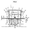
- FIG. 2 is a cut-away side view of the dry type cleaning apparatus 1.
- the cleaning tank 3 includes a cleaning tank body 6, a cleaning object fixing unit 7, and a lid 8.
- a cleaning object inlet 9 is provided at the top of the cleaning tank body 6, from which the cleaning object 2 is inserted. The entire bottom of the cleaning tank body 6 is open.
- a guide part 10 that engages the cleaning tank moving unit 4 is provided at the periphery of the top edge of the cleaning tank 3.
- the cleaning object fixing unit 7 has plural openings 12 large enough to allow a cleaning medium 11 to pass through.
- the cleaning object fixing unit 7 can be, for example, a wire mesh, a plastic mesh, or a net.
- the cleaning object fixing unit 7 is provided in the middle of the cleaning object inlet 9 and the bottom of the cleaning tank body 6.
- the cleaning tank moving unit 4 includes a pair of slide rails 13 and at least one slide stage 14.
- the slide stage 14 holds the cleaning tank 3.
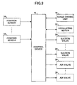
- FIG. 3 is a block diagram of a control device 15 and various input/output units.
- the slide stage 14 is driven/controlled by the control device 15.
- a stage driving unit 16 including a wire driving mechanism and a linear motor causes the slide stage 14 to intermittently move along the slide rails 13.
- the cleaning medium flying unit 5 includes a separating unit 17, an oscillating unit 18, and an elevator unit 19.
- the separating unit 17 separates the cleaning medium 11 and dust. Beneath the pair of slide rails 13, the cleaning medium flying unit 5 is provided singularly, or plural cleaning medium flying units 5 are provided with predetermined intervals.
- the separating unit 17 includes a separating member 20, a fixing plate 21, a suction pipe 22, and air pipes 23.
- the separating member 20 has many small holes and slits through which gas and dust can pass but the cleaning medium 11 cannot pass.
- the separating member 20 includes a porous member 24 (see FIG.
- the separating member 20 is provided on the top surface of the fixing plate 21 in an orthogonal direction with respect to the pair of slide rails 13, in an oscillatable manner.
- the separating member 20 is larger than the bottom opening of the cleaning tank 3, so that even when the separating member 20 oscillates, the bottom opening of the cleaning tank 3 is covered.
- the fixing plate 21 includes a suction opening 26 connected to the suction pipe 22, and air openings 27 connected to the air pipes 23.
- the air openings 27 are provided on both sides of the suction opening 26 in a direction of oscillation of the separating member 20.
- One end of the suction pipe 22 is connected to the suction opening 26 of the fixing plate 21, while the other end is connected to a suction device such as a blower.
- Each of the air pipes 23 is covered with a nozzle 28 at one end, and the nozzles 28 are connected to the air openings 27 of the fixing plate 21.
- the other ends of the air pipes 23 are connected with a compressed air supplying device.
- the suction pipe 22 and the air pipes 23 include a suction valve 29 and air valves 30, respectively, that open and close in response to control signals received from the control device 15.
- the oscillating unit 18 includes a cam 31 that engages the separating member 20 of the separating unit 17, an oscillating motor 32 that rotates the cam 31, and a position restricting unit 33 provided on the other side of the separating member 20, opposite to the side where the separating member 20 and the cam 31 are engaged.
- the position restricting unit 33 includes a compression spring and a buffer for thrusting the cam 31 against the separating member 20.
- the elevator unit 19 includes, for example, an air cylinder, an ascending edge detecting sensor, and a descending edge detecting sensor, and operates to raise or lower the separating unit 17 and the oscillating unit 18.
- a position sensor 34 is provided at the position of the cleaning medium flying unit 5 for detecting the cleaning tank 3 held by the slide stage 14 and sending signals to the control device 15 based on the detection.
- the cleaning medium 11 used in the dry type cleaning apparatus 1 is a solid having shapes of granules, rods, cylinders, fiber, or thin flakes which are made of metal, ceramics, synthetic resin, sponge, cloth, etc.
- the cleaning medium 11 can be selected according to properties such as the shape and the material of the cleaning object 2 and/or properties of dust adhering to the cleaning object 2 such as the granular diameter and the adhering strength.
- the cleaning medium 11 is preferably flake-shaped, such as resin film flakes, cloth flakes, paper flakes or thin metal flakes for removing toner granules having average granular diameters of 5 ⁇ m through 10 ⁇ m, adhering to components made of synthetic resin or metal.
- the flake-shaped cleaning medium 11 is preferable because it is extremely small in mass with respect to air resistance. Therefore, when force of an airflow is applied toward a direction of a large projection area, the cleaning medium 11 is easily accelerated by the airflow and is caused to fly at high speed. In a direction of a small projection area the air resistance is small, so that when the cleaning medium 11 is blown in this direction, the cleaning medium 11 continues to move at high speed for a long distance.
- the cleaning medium 11 has a high level of energy, so that the cleaning medium 11 applies a large force onto the cleaning object 2 when it contacts the cleaning object 2, thereby effectively removing dust adhering to the cleaning object 2. Further, as the cleaning medium 11 repeatedly circulates in the cleaning tank 3, the cleaning medium 11 is caused to contact the cleaning object 2 frequently, thereby improving cleaning efficiency.
- Air resistance of the flake-shaped cleaning medium 11 changes significantly depending on the posture of the cleaning medium 11.
- the cleaning medium 11 not only moves along the airflow but also moves in a complicated manner, such as suddenly changing direction.
- turbulent flows are generated by the openings 12 of the cleaning object fixing unit 7 and the cleaning object 2.
- the flake-shaped cleaning medium 11 is affected by air resistance in proportion to its mass, and is highly likely to follow movements of the turbulent flows. Therefore, the cleaning medium 11 is caused to move in a complicated manner, and revolves due to swirls of the turbulent flows. Accordingly, the flake-shaped cleaning medium 11 repeatedly contacts the cleaning object 2 so that cleaning efficiency is enhanced even if the cleaning object 2 has a relatively complex shape.
- the contact force concentrates at the edge of the flake-shaped cleaning medium 11. Accordingly, even though the flake-shaped cleaning medium 11 has a small mass, a sufficient amount of force can be achieved for removing dust, etc. As the contact force on the cleaning object 2 increases, the flake-shaped cleaning medium 11 bends, and therefore the force decreases. Accordingly, unlike the case of general-use materials such as a blast-shot material or an abrasive material used for barrel processing, the flake-shaped cleaning medium 11 does not apply excessive force on the cleaning object 2, so that the cleaning object 2 is not damaged.
- the flake-shaped cleaning medium 11 bends as it collides with the cleaning object 2 and a high level of viscosity resistance is received from air, so that the collision becomes inelastic, and the flake-shaped cleaning medium 11 does not bounce back.
- the flake-shaped cleaning medium 11 collides with the cleaning object 2 at an oblique angle, it comes in sliding contact with the cleaning object 2. Specifically, after colliding, the flake-shaped cleaning medium 11 slides along while scraping and rubbing a wide area of the cleaning object 2. Accordingly, the toner particles adhering to the surface of the cleaning object 2 receive a force parallel to the surface from the flake-shaped cleaning medium 11.
- the toner particles can be separated from the cleaning object 2 by using only a small force, thereby enhancing cleaning efficiency.
- Deformation and/or oscillation occurs as the flake-shaped cleaning medium 11 collides with the separating member 20, causing dust particles, etc., adhering to the cleaning object 2 to be easily separated from the cleaning object 2, and prevents them from adhering to the cleaning object 2 once again.
- the flake-shaped cleaning medium 11 can efficiently remove dust such as toner particles adhering to the cleaning object 2, only a small amount of flake-shaped cleaning medium 11 is required, thereby reducing the environmental impact and running cost.
- the flake-shaped cleaning medium 11 is piled onto the separating unit 17 of the cleaning medium flying unit 5 in advance, and the separating unit 17 and the oscillating unit 18 are lowered to a predetermined lower end by the elevator unit 19.
- the cleaning object 2 is fixed to the cleaning object fixing unit 7 in the cleaning tank 3.
- the cleaning object inlet 9 of the cleaning tank 3 is sealed with the lid 8.
- the cleaning tanks 3 containing the cleaning objects 2 are sequentially placed on the slide stages 14 and sequentially moved by the stage driving units 16.
- the control device 15 stops the stage driving unit 16 from moving the slide stage 14. Then, at a predetermined timing, the elevator unit 19 lifts the separating unit 17 and the oscillating unit 18. As the separating unit 17 and the oscillating unit 18 reach an upper end, and the separating member 20 of the separating unit 17 contacts the cleaning tank body 6 by a predetermined force, the control device 15 operates as follows.
- control device 15 opens the suction valve 29 and the air valves 30, suctions (removes) air from inside the cleaning tank 3 with the suction pipe 22, and blows compressed air from the nozzles 28 of the air pipes 23 into the cleaning tank 3 to generate a high-speed airflow within the cleaning tank 3, thereby causing the cleaning medium 11 piled on the separating member 20 to fly and stirring the cleaning medium 11.
- control device 15 drives the oscillating motor 32 of the oscillating unit 18 to oscillate the separating unit 17.
- the high-speed airflow at a flow velocity of preferably at least greater than or equal to 10 m/s, more preferably greater than or equal to 50 m/s, causes the cleaning medium 11 to fly at a speed of 5 m/s, more preferably at 10 m/s.
- FIG. 5A illustrates how the cleaning medium 11 behaves.
- the cleaning medium 11 flies through the openings 12 of the cleaning object fixing unit 7, collides with the cleaning object 2, and separates granular material such as toner particles from the cleaning object 2.
- the cleaning medium 11 and the separated particles are caused to collide with the separating member 20.
- the separated particles pass through the separating member 20 and are suctioned by the suction pipe 22.
- Particles adhering to the cleaning medium 11 are separated from the cleaning medium 11, suctioned through the separating member 20, and removed.
- the cleaning medium 11 separated from the particles is cleaned by the airflow, and accumulated on the separating member 20 around a position opposite to the suction opening 26 connected to the suction pipe 22.
- the oscillating unit 18 moves the separating member 20 in a horizontal direction as shown in FIG. 5B . Specifically, the position where the cleaning medium 11 is accumulated on the separating member 20 is moved to positions opposite to the air openings 27 connected to the nozzles 28 of the air pipes 23, so that compressed air blown out from the nozzles 28 causes the accumulated cleaning medium 11 to fly.
- the oscillating unit 18 horizontally moves the separating member 20 back and forth between the two positions opposite to the air openings 27 situated on both sides of the position opposite to the suction opening 26.
- the control device 15 closes the air valves 30 to stop the compressed air from being blown out of the nozzles 28 of the air pipes 23, and the oscillating unit 18 stops oscillating the separating member 20.
- the cleaning medium 11 flying in the cleaning tank 3 and the cleaning medium 11 adhering to the cleaning object 2, etc. is suctioned to and accumulated at the position on the separating member 20 opposite to the suction opening 26 of the separating unit 17.
- the control device 15 closes the suction valve 29 and lowers the separating unit 17 and the oscillating unit 18 with the elevator unit 19.
- the control device 15 drives the stage driving unit 16 to move forward the slide stage 14 holding the cleaning tank 3.
- the slide stage 14 holding the cleaning tank 3 containing the cleaning object 2 to be cleaned next fixed therein reaches the position above the cleaning medium flying unit 5, the slide stage 14 is stopped and the above-described process is repeated.
- plural cleaning objects 2 can be continuously cleaned, thereby enhancing cleaning efficiency. Further, only when the slide stage 14 holding the cleaning tank 3 is at the position above the cleaning medium flying unit 5, compressed air is blown in the cleaning tank 3 and air inside the cleaning tank 3 is suctioned. Therefore, unnecessary compressed air and unnecessary suction can be eliminated, which leads to energy saving.
- the separating member 20 of the separating unit 17 is moved back and forth in order to prevent the separating member 20 from being clogged by the cleaning medium 11.
- either the separating member 20 or the fixing plate 21 connected to the suction pipe 22 and the air pipes 23 is moved back and forth, so that an area on the separating member 20 where air in the cleaning tank 3 is suctioned and an area on the separating member 20 where compressed air is blown into the cleaning tank 3 are switched.
- the cleaning tank 3 is moved intermittently so that an area on the separating member 20 where air in the cleaning tank 3 is suctioned and an area on the separating member 20 where compressed air is blown into the cleaning tank 3 are switched.
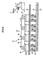
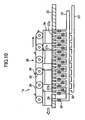
- the dry type cleaning apparatus 1a includes a linear guide 35 on which plural cleaning tanks 3a are mounted, plural suction pipes 22 and plural air pipes 23 connected to the linear guide 35, and a cleaning tank moving unit 36 for pressing the cleaning tanks 3a against the linear guide 35 and moving the cleaning tanks 3a.
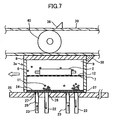
- the cleaning tank body 6 of each cleaning tank 3a includes the cleaning object inlet 9 provided at the top thereof, from which the cleaning object 2 is inserted, and the lid 8 for sealing the cleaning object inlet 9.
- the bottom of the cleaning tank body 6 is covered with the porous member 24 including many small holes and slits through which gas and dust can pass but the cleaning medium 11 cannot pass.
- the bottom edges of the side walls are entirely sealed by seal members 37, which are made of rubber or synthetic resin such as nitrile rubber or fluorovinylidene rubber.
- seal members 37 which are made of rubber or synthetic resin such as nitrile rubber or fluorovinylidene rubber.
- the cleaning object fixing unit 7 including plural openings 12 large enough to allow the cleaning medium 11 pass through.
- the top surface of the linear guide 35 is a planar guide surface, which guides the movement of the cleaning tanks 3a.
- combinations of the suction opening 26 and the air opening 27 are provided in the linear guide 35.
- the suction openings 26 are connected with the suction pipes 22, and the air openings 27 are connected with the air pipes 23 and provided near the suction openings 26 in the direction of movement of the cleaning tanks 3a. Intervals between the combinations of the suction openings 26 and the air openings 27 are narrower than the width of each cleaning tank 3a in the direction of movement thereof.
- the suction openings 26 and the air openings 27 can be slits perpendicular to the direction of movement of the cleaning tanks 3a. As shown in FIG.
- the suction openings 26 can be circular and the air openings 27 can be arc-shaped, and arranged in a staggered manner along the direction of movement of the cleaning tanks 3a.
- the position sensors 34 are provided at each position where the combinations of the suction openings 26 and the air openings 27 are provided.
- Each of the suction pipes 22 is connected to one of the suction openings 26 of the linear guide 35 at one end, while the other end is connected to a suction device such as a blower.
- Each of the air pipes 23 is covered with the nozzle 28 at one end, and the nozzles 28 are connected to the air openings 27 of the linear guide 35.
- the other ends of the air pipes 23 are connected with a compressed air supplying device.
- the suction pipes 22 and the air pipes 23 include the suction valves 29 and the air valves 30, respectively, that open and close in response to control signals received from the control device 15.
- the cleaning tank moving unit 36 is a belt conveyer mechanism including a cleaning tank driving belt 39 provided with cleaning tank fixing pawls 38, and cleaning tank pressing rollers 40 for pressing the cleaning tanks 3a against the linear guide 35.
- the cleaning tank moving unit 36 is driven by a belt driving unit 41 including a belt driving motor that operates according to belt driving control signals received from a control device 15a.
- the lid 8 of the cleaning tank 3a is opened and the flake-shaped cleaning medium 11 is put in the cleaning tank 3a.
- the cleaning medium 11 passes through the openings 12 of the cleaning object fixing unit 7 and is held on the porous member 24.
- the cleaning object 2 is placed inside the cleaning tank 3a and fixed to the cleaning object fixing unit 7.
- the lid 8 is closed so that the cleaning object inlet 9 of the cleaning tank 3a is sealed, and the cleaning tank 3a is mounted on the linear guide 35. In this manner, the cleaning tanks 3a are continuously loaded in the dry type cleaning apparatus 1a.
- the cleaning tanks 3a loaded in the dry type cleaning apparatus 1a are equally spaced apart and conveyed in a fixed direction, being guided by the linear guide 35.
- the control device 15a opens the suction valve 29 and the air valve 30, causes the suction pipe 22 to suction air from inside the cleaning tank 3a, and causes the nozzles 28 of the air pipe 23 to blow compressed air into the cleaning tank 3a.
- a high-speed airflow is generated within the cleaning tank 3a, which causes the cleaning medium 11 held on the porous member 24 to fly.
- the flying cleaning medium 11 flies through the openings 12 of the cleaning object fixing unit 7, collides with the cleaning object 2, and separates granular material such as toner particles from the cleaning object 2.
- the cleaning medium 11 and the separated particles are caused to collide with the porous member 24.
- the separated particles pass through the porous member 24 and are suctioned by the suction pipe 22. Particles adhering to the cleaning medium 11 are separated from the cleaning medium 11, suctioned through the porous member 24, and removed.
- the cleaning medium 11 separated from the particles is cleaned by the airflow, and is accumulated on the porous member 24 around a position opposite to the suction opening 26.
- the cleaning medium 11 accumulated on the porous member 24 also moves due to friction of the porous member 24. Further, the cleaning medium 11 is caused to fly again by the compressed air blown out of the air openings 27, and to collide with the cleaning object 2 and clean the cleaning object 2.
- the air openings 27 that cause the cleaning medium 11 to fly in the cleaning tank 3a and the suction openings 26 are provided as slits and arranged alternately.
- the cleaning medium 11 is collected in the shape of a slit around the suction opening 26, and the collected cleaning medium 11 is caused to fly in the cleaning tank 3a by the compressed air blow out of the slit-shaped air opening 27.
- the cleaning medium 11 is caused to collide with the moving cleaning object 2 as if to scan the entire cleaning object 2, thereby cleaning a wide area of the cleaning object 2 and enhancing cleaning efficiency.
- the suction openings 26 are circular and the air openings 27 are arc-shaped, and are arranged in a staggered manner along the direction of movement of the cleaning tanks 3a.
- the cleaning medium 11 can be caused to fly from an obliquely lower direction against the cleaning object 2 in the cleaning tank 3a, which facilitates the cleaning medium 11 colliding with the side surfaces of the cleaning object 2, and the cleaning medium 11 alternately collides with the cleaning object 2 from left and right sides. This enhances cleaning efficiency in cleaning all surfaces of the cleaning object 2 that is thick in three dimensions.
- the suction openings 26 and the air openings 27 are arranged with intervals to ensure that there is always at least one combination located under the cleaning tank 3a. Therefore, wherever the cleaning tank 3a is located on the linear guide 35, there is an airflow generated in the cleaning tank 3a so that the cleaning medium 11 is continuously flying. Accordingly, cleaning efficiency is further enhanced.
- the cleaning tanks 3a containing the cleaning objects 2 and the cleaning medium 11 are continuously moved by the cleaning tank moving unit 36, and therefore, it is possible to continuously clean the cleaning objects 2.
- some of the air openings 27 provided in the linear guide 35 can be tilted by a predetermined angle with respect to the linear guide 35, and the nozzles 28 covering ends of the air pipes 23 can be connected to the tilted air openings 27.
- the air openings 27a are tilted at 45 degrees
- the air openings 27b are perpendicular at 90 degrees
- the air openings 27c are tilted at 135 degrees.
- the nozzles 28 covering the tips of the air pipes 23 are connected to the air openings 27a, 27b, 27c, and blow out airflows in different directions into the cleaning tank 3a at different positions as the cleaning tank 3a is being moved by the linear guide 35.
- the cleaning medium 11 is accelerated by air flowing into the cleaning tank 3a being moved by the linear guide 35 at different positions at angles of 45 degrees, 90 degrees, and 135 degrees, and collides with the cleaning object 2 contained in the cleaning tank 3a. Accordingly, dirt can be removed from the cleaning object 2 facing the above-described angles. Therefore, even a three-dimensional cleaning object 2 can be uniformly cleaned.
- the air openings 27a, 27c are tilted with respect to the direction of movement of the cleaning tanks 3a.
- the air openings 27 can be tilted in any direction.
- the nozzles 28 can be configured to blow out airflows in different directions. These nozzles 28 can be connected to the air openings 27 so as to change the directions and the patterns of airflows blown into the cleaning tanks 3a.
- the cleaning medium 11 is accelerated by airflows of different directions and different patterns and therefore collides with the cleaning object 2 at various angles and by various patterns. Accordingly, the airflows compensate for each other for cleaning different areas of the cleaning object 2, so that the entire cleaning object 2 is thoroughly cleaned.
- the airflow generated by suction causes the cleaning medium 11 adhering to the cleaning object 2 to separate from the cleaning object 2 and prevents it from adhering to the cleaning object 2 once again.
- a user can open the lid 8 of the cleaning tank 3a and spray an airflow onto the cleaning object 2 with an air gun.
- the cleaning medium 11 blown off the cleaning object 2 by the airflow of the air gun is fixed onto the porous member 24 and is prevented from scattering. Accordingly, the cleaning medium 11 can be thoroughly separated from the cleaning object 2.
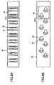
- FIG. 11 is a disassembled perspective view
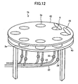
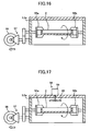
- FIG. 12 is a perspective view of a dry type cleaning apparatus 1b according to a third embodiment of the present invention.
- the plural cleaning tanks 3a are provided along the circumference of a rotating table 42, which is rotated by a table driving unit 43.
- Plural combinations of the suction openings 26 and the air openings 27 connected to the suction pipes 22 and the air pipes 23 are provided along the circumference of the table driving unit 43, which matches the circumference of the rotating table 42 provided with the cleaning tanks 3a.
- the suction openings 26 and the air openings 27 are not provided under an inlet 44 from which the cleaning object 2 is inserted.
- this turntable-type dry type cleaning apparatus 1b a sufficient amount of the cleaning medium 11 and the cleaning object 2 are put into the cleaning tank 3a from the inlet 44.
- the rotating table 42 is intermittently rotated by a constant feed angle, so that the cleaning tanks 3a are moved to and stopped at positions where the suction openings 26 and the air openings 27 are provided in the table driving unit 43. At these positions, the suction valves 29 and the air valves 30 are opened so that the suction pipes 22 suction air inside the cleaning tanks 3a, and compressed air is blown into the cleaning tanks 3a from the nozzles 28 of the air pipes 23.
- the cleaning medium 11 wears out as it is continuously used in the dry type cleaning apparatus 1b for cleaning the cleaning object 2.
- the cleaning medium 11 is discharged by being suctioned or discharged by adhering to the cleaning object 2, such that the cleaning medium 11 eventually decreases in amount. Accordingly, it is necessary to periodically replenish the cleaning medium 11.
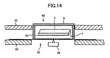
- a cleaning medium inlet section 45, a measuring section 46, and a discharge section 47 are provided along the cleaning tank moving path for the cleaning tanks 3a of the rotating table 42 on an upstream side of the inlet 44 in the direction of rotation of the rotating table 42.
- a cleaning medium automatic insertion device 48 is connected to the cleaning medium inlet section 45.
- the measuring section 46 is provided with a cleaning medium amount measuring unit 49.
- the cleaning medium automatic insertion device 48 includes a hopper 50 for temporarily accumulating the cleaning medium 11, a supplying screw 51, and a cleaning medium supplying motor 52 that drives the supplying screw 51.
- a hopper 50 for temporarily accumulating the cleaning medium 11, a supplying screw 51, and a cleaning medium supplying motor 52 that drives the supplying screw 51.
- an opening 53 is formed at the position corresponding to the measuring section 46 of the table driving unit 43.
- the opening 53 is provided with, for example, a weighted sensor functioning as the cleaning medium amount measuring unit 49.
- the cleaning medium amount measuring unit 49 is connected to a control unit 15b that controls operations of a table driving motor 54 of the table driving unit 43, the cleaning medium supplying motor 52, the suction valves 29, and the air valves 30.
- the dry type cleaning apparatus 1b including the cleaning medium automatic insertion device 48 and the cleaning medium amount measuring unit 49, a certain amount of the cleaning medium 11 is put in the cleaning tank 3a from the cleaning medium automatic insertion device 48 at the cleaning medium inlet section 45.
- this cleaning tank 3a moves to the inlet 44, the cleaning object 2 is inserted in the cleaning tank 3a and the rotating table 42 is intermittently rotated at a constant feed angle. Accordingly, the cleaning objects 2 contained in the cleaning tanks 3a are cleaned.
- the cleaning tank 3a rotates once and reaches the discharge section 47, the cleaning object 2 is retrieved from the cleaning tank 3a.
- the cleaning medium amount measuring unit 49 measures the weight of the cleaning tank 3a and sends the value to the control unit 15b.
- the control unit 15b calculates the amount of cleaning medium 11 remaining in the cleaning tank 3a based on the weights of each of the cleaning tanks 3a registered in advance and the measurement value received from the cleaning medium amount measuring unit 49.
- the calculated amount of the remaining cleaning medium 11 and the turnover number of the table driving unit 43 are loaded in a storage device.
- the control unit 15b compares the remaining amount of the cleaning medium 11 and a threshold indicating a prescribed amount of the cleaning medium 11. If the control unit 15b finds that the remaining amount is less than or equal to the threshold in one of the cleaning tanks 3a, the cleaning medium 11 is replenished as follows.
- the control unit 15b drives the cleaning medium automatic insertion device 48 to replenish the cleaning medium 11 in the cleaning tank 3a.
- the control unit 15b drives the cleaning medium automatic insertion device 48 such that the remaining amount of the cleaning medium 11 reaches a predetermined standard value.
- a weighted sensor is used as the cleaning medium amount measuring unit 49.
- a photoelectric sensor can be provided in each of the cleaning tanks 3a to measure the cleaning medium accumulation amount and/or the number of flying cleaning media in order to obtain the remaining amount of the cleaning medium 11.
- the cleaning medium automatic insertion device 48 replenishes the cleaning medium 11 according to the remaining amount of cleaning medium 11.
- the cleaning medium automatic insertion device 48 can replenish a prescribed amount of the cleaning medium 11 according to a number of rotations of the cleaning tank 3a or a number of times the cleaning medium 11 has been used.
- the cleaning tanks 3, 3a of the dry type cleaning apparatus 1, 1a, 1b employ a wire mesh as the cleaning object fixing unit 7, which has the openings 12 that are large enough for the cleaning medium 11 to pass though.
- the cleaning object fixing unit 7 can be configured by cleaning object fixtures 55a, 55b, a rotating unit 56, and a rotation transmitting unit 57.
- the cleaning object fixtures 55a, 55b are rotatable components provided at opposing sides of the cleaning tank body 6 of the cleaning tank 3, and hold the cleaning object 2 by sandwiching the cleaning object 2.
- the rotating unit 56 is a friction pulley that is caused to rotate by relative movements between the cleaning tank 3 and the cleaning medium flying unit 5 or relative movements between the cleaning tank 3a and the linear guide 35 or the table driving unit 43.
- the rotation transmitting unit 57 is a group of bevel gears that transmits the rotation of the rotating unit 56 to the rotational axis of the cleaning object fixtures 55a, 55b.
- All surfaces of the cleaning object 2 can be cleaned at an even higher speed as the cleaning object 2 is rotated (posture of the cleaning object 2 is changed) in association with the oscillation of the separating unit 17 or the movement of the cleaning tank 3a, while the cleaning medium 11 is being caused to fly in the cleaning tank 3, or while the separating unit 17 of the cleaning medium flying unit 5 is being oscillated, or while the cleaning tank 3a is being moved along the linear guide 35 or the table driving unit 43 while the cleaning medium 11 is flying in the cleaning tank 3a.
- the rotating unit 56 rotates the cleaning object fixtures 55a, 55b due to relative movements between the cleaning tank 3 and the cleaning medium flying unit 5 or relative movements between the cleaning tank 3a and the linear guide 35 or the table driving unit 43.
- the rotational axis of the cleaning object fixtures 55a, 55b can be caused to rotate by a rotation driving device such as a driving motor.
- a cleaning medium accelerating unit 58 can be provided in the cleaning tanks 3, 3a, for accelerating the cleaning medium 11 flying in the cleaning tanks 3, 3a.
- the cleaning medium accelerating unit 58 can be a cleaning medium accelerating propeller 60 connected to a motor 59 driven by batteries, or an air blowing nozzle connected to a compressed air generating device.
- the cleaning medium accelerating unit 58 is arranged at a position opposite to the air opening 27, which blows airflows into the cleaning tank 3, 3a, across the cleaning object 2.
- the cleaning medium accelerating unit 58 By arranging the cleaning medium accelerating unit 58 at a position opposite to the air opening 27, which blows airflows into the cleaning tank 3, 3a, across the cleaning object 2, the cleaning medium 11 accelerated by the airflow blown in from the air opening 27 and the cleaning medium 11 accelerated by the airflow from the cleaning medium accelerating unit 58 collide with the cleaning object 2 to remove dirt, so that all surfaces of the cleaning object 2 are uniformly cleaned.
- the cleaning medium accelerating unit 58 is arranged at a position opposite to the air opening 27, which blows airflows into the cleaning tank 3, 3a, across the cleaning object 2.
- the cleaning medium accelerating unit 58 can be arranged at a position where the airflow blown out from the air opening 27 is accelerated, thereby accelerating the cleaning medium 11 even further, so that persistent dirt can be quickly removed.
- the cleaning tank 3, 3a can be moved smoothly without being obstructed by wires from a power source.
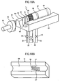
- FIG. 18A is a perspective view of a dry type cleaning apparatus 1c according to a fourth embodiment of the present invention.
- the dry type cleaning apparatus 1c includes a cleaning tank 3b, a slide guide 61, the suction pipe 22 and the air pipes 23 connected to the slide guide 61, and a cleaning tank driving unit 62.
- the cleaning tank 3b has a cylindrical shape having a certain length. Except for edges 63 on both sides of the cleaning tank 3b, the outer periphery is covered by the porous member 24 having many small holes and slits through which gas and dust can pass but the cleaning medium 11 cannot pass. Inside the cleaning tank 3b is provided a bag-shaped cleaning object fixing unit 7 having the plural openings 12 large enough to allow the cleaning medium 11 to pass through. Both of the edges 63 of the cleaning tank 3b have lids 64 that can open and close. Each of the lids 64 has a connecting part 65 including a groove and processes that engage the cleaning tank driving unit 62.
- the slide guide 61 includes a semi-cylindrical guide groove 66 and a semi-cylindrical cover 67 covering all or part of the guide groove 66.
- the suction opening 26 and the air openings 27 are alternately provided at predetermined positions in the forms of curved grooves.
- seal members 68 for sealing both edges 63 of the cleaning tank 3b are provided inside the cover 67.
- One end of the suction pipe 22 including the suction valve 29 is connected to the suction opening 26 of the slide guide 61, while the other end is connected to a suction device such as a blower.
- Each of the air pipes 23 including the air valves 30 is covered with the nozzle 28 at one end, and the nozzles 28 are connected to the air openings 27 of the slide guide 61.
- the other ends of the air pipes 23 are connected with a compressed air supplying device.
- the cleaning tank driving unit 62 includes a cleaning tank feed unit 69, a rotating motor provided at the edge of the cleaning tank feeding unit 69, and a cleaning tank rotating unit 70 including a rotating motor and a rotation transmitting unit that engages the connecting part 65 of the lid 64 of the cleaning tank 3b, and transmits rotation to the cleaning tank 3b.
- the cleaning tank feed unit 69 is configured by, for example, an air cylinder, a feed motor, and a feed screw mechanism.
- the lid 64 of the cleaning tank 3b is opened outside the slide guide 61, the cleaning object 2 and the cleaning medium 11 are put in the cleaning tank 3b, and the cleaning object 2 is fixed to the bag-shaped cleaning object fixing unit 7. Then, the lid 64 of the cleaning tank 3b is closed, and as shown in FIG. 18A , the cleaning tank 3b is loaded from an inlet of the slide guide 61. Next, the cleaning tank driving unit 62 engages the connecting part 65 of the lid 64 of the cleaning tank 3b, and the cleaning tank 3b is pushed forward to a predetermined position of the slide guide 61 where the suction opening 26 and the air openings 27 are provided.
- the cleaning tank 3b When the cleaning tank 3b is pushed forward to the predetermined position, the cleaning tank 3b is stopped and then rotated.
- the suction valve 29 and the air valves 30 When the cleaning tank 3b is rotating, the suction valve 29 and the air valves 30 are opened so that the suction pipes 22 suction air inside the cleaning tank 3b, and compressed air is blown into the cleaning tank 3b from the nozzles 28 of the air pipes 23. Accordingly, high-speed airflows are generated inside the cleaning tank 3b, which cause the cleaning medium 11 to fly and collide with the cleaning object 2, thereby cleaning the cleaning object 2. While cleaning the cleaning object 2, the cleaning medium 11 flies and rotates in synchronization with the rotation of the cleaning tank 3b.
- the cleaning medium 11 collides with all surfaces of the cleaning object 2, so that the cleaning medium 11 uniformly cleans all surfaces of the cleaning object 2.
- the suction valve 29 and the air valves 30 are closed, the rotation of the cleaning tank 3b is stopped, and the cleaning tank 3b is sent out through a discharge outlet of the slide guide 61.
- the next cleaning tank 3b is inserted and the cleaning process is performed.
- the cleaning medium 11 is caused to flow by rotating the cleaning tank 3b so that all surfaces of the cleaning object 2 are uniformly cleaned, while preventing the porous member 24 being clogged.
- dust and granular material adhering to a cleaning object is removed with a cleaning medium caused to flow by a high-speed airflow.
- a porous member is provided to separate the removed dust and granular material from the cleaning medium.
- An area on the porous member where the separated dust and granular material are suctioned and an area on the porous member that receives an airflow for causing the cleaning medium to flow can be changed.
- the cleaning medium separated from the dust and granular material and accumulated onto the porous member is caused to fly again by an airflow. Accordingly, the porous member is prevented from being clogged by the cleaning medium and the cleaning medium can be continuously caused to fly, thereby enhancing cleaning efficiency.
- one or plural cleaning medium flying units are provided with predetermined intervals beneath a cleaning tank moving unit that moves cleaning tanks. While the cleaning tank moving unit is moving the cleaning tanks, the cleaning medium flying units cause cleaning medium inside the cleaning tanks to flow. Accordingly, it is possible to continuously load cleaning tanks, and cleaning objects contained in the cleaning tanks can be continuously cleaned.
- the cleaning object contained in the cleaning tank can be continuously cleaned while preventing the porous member in the cleaning tank from being clogged, thereby enhancing cleaning efficiency.
- plural cleaning tanks can be continuously loaded with a simple structure so that many cleaning objects can be efficiently cleaned.
- plural cleaning tanks can be continuously loaded and a relatively long cleaning tank moving path can be realized within a small space, so that cleaning objects can be continuously cleaned.
- the cleaning medium and the cleaning object are loaded and retrieved at a single inlet, thereby reducing the user's load.
- the porous member of the cleaning tank is surely prevented from being clogged.
- the cleaning medium collides with the cleaning object overall, so that a large area of the cleaning object is cleaned, thereby enhancing cleaning efficiency.
- the cleaning medium can be caused to fly from an obliquely lower direction against the cleaning object, so that the cleaning medium easily collides with the side surfaces of the cleaning object, and the cleaning medium alternately collides with the cleaning object from left and right sides, thereby enhancing cleaning efficiency in cleaning all surfaces of a cleaning object that is thick in three dimensions.
- all surfaces of the cleaning object can be efficiently cleaned with a posture changing unit.
- the posture changing unit is caused to operate by movements of the cleaning tank, and thus does not require special driving means.
- the cleaning medium can be thoroughly separated from the cleaning object.
- the cleaning medium accelerated by airflows of different angles and different patterns is caused to collide with the cleaning object inside the cleaning tank, so that even a three-dimensional cleaning object can be uniformly cleaned.
- the cleaning object can be cleaned even more efficiently, and all surfaces of the cleaning object can be uniformly cleaned.
- the cleaning medium in the cleaning tank can be easily replenished.
- the consumption amount of the cleaning medium can be surely detected.
- the cleaning medium in the cleaning tank can be automatically replenished and the amount of cleaning medium in the cleaning tank can be appropriately maintained, so that the cleaning objects can be consistently and thoroughly cleaned.
- all surfaces of the cleaning object can be uniformly cleaned while preventing the porous member in the cleaning tank being clogged.
Description
- The present invention relates generally to dry type cleaning apparatuses and dry type cleaning methods for removing, by using solid cleaning media and without using water or solvents, dust and granular material, e.g., toner having average granular diameters of 5 µm through 10 µm. The toner is used in electrophotographic image forming apparatuses such as copiers and laser printers, where it adheres to various cleaning objects such as components having relatively complex shapes. More particularly, the present invention relates to a dry type cleaning apparatus and a dry type cleaning method with which cleaning objects can be continuously loaded and cleaned, thereby enhancing operability.
- Manufacturers of office equipment such as copiers, facsimile machines, and printers are actively involved in recycling activities for the purpose of realizing a resource-recycling society. Specifically, the manufactures recover used products and units from users, and disassemble, clean, and reassemble the used products to be reused as components or resin material. In order to reuse components of these products and units, toner particles adhering to disassembled components and units need to be removed and cleaned off. Thus, reduction of cleaning costs and environmental impact is a major issue.
-
Patent Documents 1, 2 (see below) disclose wet type cleaning apparatuses that use water and solvents for removing dirt such as toner adhering to the components and units. The cleaning apparatus disclosed inPatent Document 1 includes a mesh cleaning basket with a large aperture. A cleaning object is fixed inside the cleaning basket, and the cleaning basket is conveyed by a conveying unit such as a belt conveyer along a path on which a cleaning solvent such as cleaning jet water is sprayed. The cleaning solvent is sprayed from above and from the sides of the cleaning basket being conveyed on the path. The cleaning solvent passes through the aperture and meshes of the cleaning basket, and collides with the cleaning object to clean the cleaning object. Cleaning baskets containing cleaning objects fixed inside are continuously loaded into the conveying unit, so that plural cleaning objects are continuously cleaned. - In the cleaning apparatus disclosed in
Patent Document 2, multiple granular materials such as gel, gel foam, glass, ceramics, and synthetic resin are fluidized in a cleaning tank by gas flows. Liquid such as water and silicon liquid, which have the same relative density as the granular materials, is supplied in the cleaning tank. The supplied liquid is dispersed within granular fluid layers, thereby forming solid-liquid aggregates of appropriate sizes. Accordingly, the effective gas passage area is decreased so as to increase the gas flow velocity passing through the granular layers. This generates a peculiar three-phase stream in which fluidization of granular layers is activated, and the peculiar three-phase stream is caused to collide with the cleaning object so as to enhance cleaning efficiency. - When this wet type cleaning apparatus is used for cleaning off dirt such as toner adhering to components and units, it is necessary to perform processes such as disposing of waste water including toner and drying the components after being cleaned. These processes consume large amounts of energy and have high environmental impact.
- A dry type cleaning method employing airblowing is insufficient for cleaning off toner having a high level of adhesion strength. Thus, an aftertreatment is required to manually wipe off the remaining toner. Accordingly, cleaning is a bottleneck process in reusing/recycling products.
-
Patent Document 3 discloses a dry type cleaning apparatus that removes dust adhering to a cleaning object as follows. A rotatable container is rotated, which container contains plural cleaning objects to which dust is adhering in an electrostatic manner, and spherical or cubic contact members made of an elastic material such as flexible urethane foam. While the container is being rotated, positive/negative aero-ions necessary for neutralizing electrical charges of the cleaning objects inside the container are emitted by ignition electrodes, and the aero-ions are sprayed onto the cleaning objects. The rotatable container is a cylinder, and the cleaning objects and the contact members are inserted into the rotating cylinder from an inlet part provided on one end of the cylinder. After the cleaning objects and the contact members are moved from an upstream side to a downstream side, the cleaning objects and the contact members are retrieved separately. Cleaning objects are continuously cleaned in the above manner. -
Patent Document 4 discloses a dry type cleaning apparatus including a cleaning tank with a wire-mesh inner board for mounting a cleaning object. In between the inner board and the bottom of the cleaning tank there is provided a gas blowout section. Spherical granules having diameters of 5 mm to 10 mm made of steel, alumina, ceramics, plastic, etc., are placed in the gas blowout section. The gas blowout section has an aperture through which gas can pass but the granules cannot pass. Air from the cleaning tank is introduced through an inlet provided on a top lid, and external air is taken in from an inlet provided on the bottom of the cleaning tank, thereby forming a gas flow in the cleaning tank. The gas flow incorporates the granules into jet flows, and the jet flows are made to collide with the cleaning object, so as to clean the cleaning object. - Patent Document 1: Japanese Patent No.
2791862
Patent Document 2: Japanese Laid-Open Patent Application No.2002-28581
Patent Document 3: Japanese Patent No.3288462
Patent Document 4: Japanese Laid-Open Patent Application No.2003-190247 - In the dry type cleaning apparatus disclosed in
Patent Document 3, cleaning objects are continuously cleaned by continuously moving the cleaning objects and the contact members from an upstream side to a downstream side in the rotating cylinder. Accordingly, the cleaning objects may contact and damage each other. Therefore, it is difficult to apply this technology to fragile resin products. - With the dry type cleaning apparatus disclosed in
Patent Document 4, at least one cleaning object is loaded into the cleaning tank and removed after a certain amount of time. Therefore, cleaning objects cannot be continuously cleaned by this method. - The present invention provides a dry type cleaning apparatus and a dry type cleaning method in which one or more of the above-described disadvantages is eliminated.
- A preferred embodiment of the present invention provides a dry type cleaning apparatus and a dry type cleaning method with which cleaning objects of various types of materials can be efficiently cleaned, and cleaning objects can be continuously loaded into the apparatus to be continuously cleaned.
- An embodiment of the present invention provides a dry type cleaning apparatus for removing dust adhering to a cleaning object with a cleaning medium caused to flow by a high-speed airflow, the dry type cleaning apparatus including a cleaning tank; a separating unit; an air supply/discharge unit; and a moving unit; wherein the cleaning tank includes a cleaning object inlet from which the cleaning object is inserted, a lid configured to seal the cleaning object inlet, a bottom part that is open, and a cleaning object fixing unit provided between the cleaning object inlet and the bottom part, including plural openings through which the cleaning medium can pass, the separating unit includes a porous member provided at the bottom part of the cleaning tank, the porous member including holes through which air, dust, and granular material can pass but the cleaning medium cannot pass, the air supply/discharge unit includes a blowing unit configured to blow air into the cleaning tank through the porous member of the separating unit, and a suction unit configured to suction air from the cleaning tank through the porous member of the separating unit and discharge the suctioned air outside, and the moving unit is configured to move the separating unit and the air supply/discharge unit relatively to each other.
- An embodiment of the present invention provides a dry type cleaning apparatus for removing dust adhering to a cleaning object with a cleaning medium caused to flow by a high-speed airflow, the dry type cleaning apparatus including plural cleaning tanks; a cleaning tank guiding unit; an air supply/discharge unit; and a cleaning tank moving unit; wherein each of the cleaning tanks includes a cleaning object inlet from which the cleaning object is inserted, a lid configured to seal the cleaning object inlet, a bottom part covered by a porous member including holes through which air, dust, and granular material can pass but the cleaning medium cannot pass, and a cleaning object fixing unit provided between the cleaning object inlet and the bottom part, including plural openings through which the cleaning medium can pass the cleaning tank guiding unit includes a guiding surface configured to guide movement of the cleaning tanks mounted thereon, the guiding surface being provided at a top of the cleaning tank guiding unit, and plural combinations arranged along a direction of movement of the cleaning tanks, each of the combinations including a suction opening and a blowing opening connected to the air supply/discharge unit, the air supply/discharge unit includes blowing units configured to blow air into the cleaning tank through the porous member of the cleaning tank, the blowing units being connected to the blowing openings of the cleaning tank guiding unit, and suction units configured to suction air from the cleaning tank through the porous member of the cleaning tank and discharge the suctioned air outside, the suction units being connected to the suction openings of the cleaning tank guiding unit, and the cleaning tank moving unit is configured to move the cleaning tanks along the guiding surface of the cleaning tank guiding unit.
- An embodiment of the present invention provides a dry type cleaning method of removing dust adhering to a cleaning object with a cleaning medium caused to flow by a high-speed airflow, and separating the removed dust from the cleaning medium with a porous member including holes through which air, dust, and granular material can pass but the cleaning medium cannot pass, the dry type cleaning method including a step of switching an area on the porous member where air is received to cause the cleaning medium to flow and an area on the porous member where suction air is received to suction the dust separated from the cleaning medium.
- According to the present invention, a dry type cleaning apparatus and a dry type cleaning method are provided, with which cleaning objects of various types of materials can be efficiently cleaned, and cleaning objects can be continuously loaded into the apparatus to be continuously cleaned.
- Other objects, features and advantages of the present invention will become more apparent from the following detailed description when read in conjunction with the accompanying drawings, in which:
-
FIG. 1 is a schematic diagram of a dry type cleaning apparatus according to a first embodiment of the present invention; -
FIG. 2 is a cut-away side view of the dry type cleaning apparatus shown inFIG. 1 ; -
FIG. 3 is a block diagram of a control device and various input/output units according to the first embodiment; -
FIGS. 4A, 4B are schematic diagrams of a cleaning medium removing granular materials adhering to a cleaning object; -
FIGS. 5A, 5B are cut-away side views of the dry type cleaning apparatus shown inFIG. 1 in which cleaning medium is flying; -
FIG. 6 is a schematic diagram of a dry type cleaning apparatus according to a second embodiment of the present invention; -
FIG. 7 is a partial cut-away side view of the dry type cleaning apparatus shown inFIG. 6 ; -
FIGS. 8A, 8B are schematic diagrams of arrangements of suction openings and air openings provided in a linear guide of the dry type cleaning apparatus shown inFIG. 6 ; -
FIG. 9 is a block diagram of a control device and various input/output units according to the second embodiment; -
FIG. 10 is a variation of the dry type cleaning apparatus according to the second embodiment; -
FIG. 11 is a disassembled perspective view of a dry type cleaning apparatus according to a third embodiment of the present invention; -
FIG. 12 is a perspective view of the dry type cleaning apparatus according to the third embodiment; -
FIG. 13 is a variation of the dry type cleaning apparatus according to the third embodiment; -
FIG. 14 is a partial cut-away side view of a measuring section including a cleaning medium amount measuring unit; -
FIG. 15 is a block diagram of a control device and various input/output units according to the third embodiment; -
FIG. 16 is a cut-away side view of a cleaning tank provided with cleaning object fixtures; -
FIG. 17 is a cut-away side view of a cleaning tank provided with a cleaning medium accelerating unit; -
FIG. 18A is a dry type cleaning apparatus according to a fourth embodiment of the present invention; and -
FIG. 18B is a perspective view of a slide guide shown inFIG. 18A . - A description is given, with reference to the accompanying drawings, of embodiments of the present invention.
-
FIG. 1 is a schematic diagram of a drytype cleaning apparatus 1 according to a first embodiment of the present invention. The drytype cleaning apparatus 1 removes dust such as toner adhering to acleaning object 2, with a cleaning medium flowing on a high-speed airflow. The drytype cleaning apparatus 1 includes acleaning tank 3, a cleaningtank moving unit 4, and a cleaning medium flying unit 5 (seeFIG. 2 ). -
FIG. 2 is a cut-away side view of the drytype cleaning apparatus 1. Thecleaning tank 3 includes acleaning tank body 6, a cleaningobject fixing unit 7, and alid 8. A cleaningobject inlet 9 is provided at the top of thecleaning tank body 6, from which thecleaning object 2 is inserted. The entire bottom of thecleaning tank body 6 is open. Aguide part 10 that engages the cleaningtank moving unit 4 is provided at the periphery of the top edge of thecleaning tank 3. The cleaningobject fixing unit 7 hasplural openings 12 large enough to allow a cleaningmedium 11 to pass through. The cleaningobject fixing unit 7 can be, for example, a wire mesh, a plastic mesh, or a net. The cleaningobject fixing unit 7 is provided in the middle of the cleaningobject inlet 9 and the bottom of thecleaning tank body 6. - The cleaning
tank moving unit 4 includes a pair of slide rails 13 and at least oneslide stage 14. Theslide stage 14 holds thecleaning tank 3.FIG. 3 is a block diagram of a control device 15 and various input/output units. Theslide stage 14 is driven/controlled by the control device 15. For example, astage driving unit 16 including a wire driving mechanism and a linear motor causes theslide stage 14 to intermittently move along the slide rails 13. - The cleaning
medium flying unit 5 includes a separatingunit 17, an oscillatingunit 18, and anelevator unit 19. The separatingunit 17 separates the cleaningmedium 11 and dust. Beneath the pair of slide rails 13, the cleaningmedium flying unit 5 is provided singularly, or plural cleaningmedium flying units 5 are provided with predetermined intervals. The separatingunit 17 includes a separatingmember 20, a fixingplate 21, asuction pipe 22, andair pipes 23. The separatingmember 20 has many small holes and slits through which gas and dust can pass but the cleaningmedium 11 cannot pass. The separatingmember 20 includes a porous member 24 (seeFIG. 1 ), e.g., a mesh such as a wire mesh and a plastic mesh, a net, non-woven fabric, a sponge film, a punch-metal plate, a honeycomb plate, a porous plate, and a slit plate, and a holding frame 25 (seeFIG. 1 ) for holding theporous member 24. The separatingmember 20 is provided on the top surface of the fixingplate 21 in an orthogonal direction with respect to the pair of slide rails 13, in an oscillatable manner. The separatingmember 20 is larger than the bottom opening of thecleaning tank 3, so that even when the separatingmember 20 oscillates, the bottom opening of thecleaning tank 3 is covered. The fixingplate 21 includes asuction opening 26 connected to thesuction pipe 22, andair openings 27 connected to theair pipes 23. Theair openings 27 are provided on both sides of thesuction opening 26 in a direction of oscillation of the separatingmember 20. One end of thesuction pipe 22 is connected to thesuction opening 26 of the fixingplate 21, while the other end is connected to a suction device such as a blower. Each of theair pipes 23 is covered with anozzle 28 at one end, and thenozzles 28 are connected to theair openings 27 of the fixingplate 21. The other ends of theair pipes 23 are connected with a compressed air supplying device. Thesuction pipe 22 and theair pipes 23 include asuction valve 29 andair valves 30, respectively, that open and close in response to control signals received from the control device 15. The oscillatingunit 18 includes acam 31 that engages the separatingmember 20 of the separatingunit 17, anoscillating motor 32 that rotates thecam 31, and aposition restricting unit 33 provided on the other side of the separatingmember 20, opposite to the side where the separatingmember 20 and thecam 31 are engaged. Theposition restricting unit 33 includes a compression spring and a buffer for thrusting thecam 31 against the separatingmember 20. Theelevator unit 19 includes, for example, an air cylinder, an ascending edge detecting sensor, and a descending edge detecting sensor, and operates to raise or lower theseparating unit 17 and theoscillating unit 18. Aposition sensor 34 is provided at the position of the cleaningmedium flying unit 5 for detecting thecleaning tank 3 held by theslide stage 14 and sending signals to the control device 15 based on the detection. - The cleaning
medium 11 used in the drytype cleaning apparatus 1 is a solid having shapes of granules, rods, cylinders, fiber, or thin flakes which are made of metal, ceramics, synthetic resin, sponge, cloth, etc. The cleaningmedium 11 can be selected according to properties such as the shape and the material of thecleaning object 2 and/or properties of dust adhering to thecleaning object 2 such as the granular diameter and the adhering strength. In an image forming apparatus employing an electrophotographic method, the cleaningmedium 11 is preferably flake-shaped, such as resin film flakes, cloth flakes, paper flakes or thin metal flakes for removing toner granules having average granular diameters of 5 µm through 10 µm, adhering to components made of synthetic resin or metal. - The flake-shaped
cleaning medium 11 is preferable because it is extremely small in mass with respect to air resistance. Therefore, when force of an airflow is applied toward a direction of a large projection area, the cleaningmedium 11 is easily accelerated by the airflow and is caused to fly at high speed. In a direction of a small projection area the air resistance is small, so that when the cleaningmedium 11 is blown in this direction, the cleaningmedium 11 continues to move at high speed for a long distance. The cleaningmedium 11 has a high level of energy, so that the cleaningmedium 11 applies a large force onto thecleaning object 2 when it contacts thecleaning object 2, thereby effectively removing dust adhering to thecleaning object 2. Further, as the cleaningmedium 11 repeatedly circulates in thecleaning tank 3, the cleaningmedium 11 is caused to contact thecleaning object 2 frequently, thereby improving cleaning efficiency. - Air resistance of the flake-shaped cleaning medium 11 changes significantly depending on the posture of the cleaning
medium 11. Thus, the cleaningmedium 11 not only moves along the airflow but also moves in a complicated manner, such as suddenly changing direction. Further, according to the effect of the high-speed airflow, turbulent flows are generated by theopenings 12 of the cleaningobject fixing unit 7 and thecleaning object 2. The flake-shapedcleaning medium 11 is affected by air resistance in proportion to its mass, and is highly likely to follow movements of the turbulent flows. Therefore, the cleaningmedium 11 is caused to move in a complicated manner, and revolves due to swirls of the turbulent flows. Accordingly, the flake-shapedcleaning medium 11 repeatedly contacts thecleaning object 2 so that cleaning efficiency is enhanced even if thecleaning object 2 has a relatively complex shape. - As shown in
FIGS. 4A, 4B , when the flake-shapedcleaning medium 11 collides with thecleaning object 2 from the edge of the flake-shapedcleaning medium 11, the contact force concentrates at the edge of the flake-shapedcleaning medium 11. Accordingly, even though the flake-shapedcleaning medium 11 has a small mass, a sufficient amount of force can be achieved for removing dust, etc. As the contact force on thecleaning object 2 increases, the flake-shapedcleaning medium 11 bends, and therefore the force decreases. Accordingly, unlike the case of general-use materials such as a blast-shot material or an abrasive material used for barrel processing, the flake-shapedcleaning medium 11 does not apply excessive force on thecleaning object 2, so that thecleaning object 2 is not damaged. Further, the flake-shapedcleaning medium 11 bends as it collides with thecleaning object 2 and a high level of viscosity resistance is received from air, so that the collision becomes inelastic, and the flake-shapedcleaning medium 11 does not bounce back. When the flake-shapedcleaning medium 11 collides with thecleaning object 2 at an oblique angle, it comes in sliding contact with thecleaning object 2. Specifically, after colliding, the flake-shapedcleaning medium 11 slides along while scraping and rubbing a wide area of thecleaning object 2. Accordingly, the toner particles adhering to the surface of thecleaning object 2 receive a force parallel to the surface from the flake-shapedcleaning medium 11. Thus, the toner particles can be separated from thecleaning object 2 by using only a small force, thereby enhancing cleaning efficiency. - Deformation and/or oscillation occurs as the flake-shaped
cleaning medium 11 collides with the separatingmember 20, causing dust particles, etc., adhering to thecleaning object 2 to be easily separated from thecleaning object 2, and prevents them from adhering to thecleaning object 2 once again. - As the flake-shaped
cleaning medium 11 can efficiently remove dust such as toner particles adhering to thecleaning object 2, only a small amount of flake-shapedcleaning medium 11 is required, thereby reducing the environmental impact and running cost. - A description is given of an operation of causing the flake-shaped
cleaning medium 11 to fly and circulate inside thecleaning tank 3 to remove dust such as toner particles adhering to thecleaning object 2. - The flake-shaped
cleaning medium 11 is piled onto the separatingunit 17 of the cleaningmedium flying unit 5 in advance, and the separatingunit 17 and theoscillating unit 18 are lowered to a predetermined lower end by theelevator unit 19. In this condition, on the cleaning tank insertion side of the slide rails 13, thecleaning object 2 is fixed to the cleaningobject fixing unit 7 in thecleaning tank 3. Then, the cleaningobject inlet 9 of thecleaning tank 3 is sealed with thelid 8. Thecleaning tanks 3 containing the cleaning objects 2 are sequentially placed on the slide stages 14 and sequentially moved by thestage driving units 16. When theslide stage 14 holding thecleaning tank 3 reaches the position of the cleaningmedium flying unit 5 and theposition sensor 34 detects thecleaning tank 3 held by theslide stage 14, the control device 15 stops thestage driving unit 16 from moving theslide stage 14. Then, at a predetermined timing, theelevator unit 19 lifts theseparating unit 17 and theoscillating unit 18. As the separatingunit 17 and theoscillating unit 18 reach an upper end, and the separatingmember 20 of the separatingunit 17 contacts thecleaning tank body 6 by a predetermined force, the control device 15 operates as follows. That is, the control device 15 opens thesuction valve 29 and theair valves 30, suctions (removes) air from inside thecleaning tank 3 with thesuction pipe 22, and blows compressed air from thenozzles 28 of theair pipes 23 into thecleaning tank 3 to generate a high-speed airflow within thecleaning tank 3, thereby causing the cleaningmedium 11 piled on the separatingmember 20 to fly and stirring the cleaningmedium 11. At the same time, the control device 15 drives theoscillating motor 32 of theoscillating unit 18 to oscillate the separatingunit 17. The high-speed airflow, at a flow velocity of preferably at least greater than or equal to 10 m/s, more preferably greater than or equal to 50 m/s, causes the cleaningmedium 11 to fly at a speed of 5 m/s, more preferably at 10 m/s. -
FIG. 5A illustrates how the cleaningmedium 11 behaves. The cleaningmedium 11 flies through theopenings 12 of the cleaningobject fixing unit 7, collides with thecleaning object 2, and separates granular material such as toner particles from thecleaning object 2. As an airflow is generated by suction from thesuction pipe 22, the cleaningmedium 11 and the separated particles are caused to collide with the separatingmember 20. The separated particles pass through the separatingmember 20 and are suctioned by thesuction pipe 22. Particles adhering to the cleaningmedium 11 are separated from the cleaningmedium 11, suctioned through the separatingmember 20, and removed. The cleaningmedium 11 separated from the particles is cleaned by the airflow, and accumulated on the separatingmember 20 around a position opposite to thesuction opening 26 connected to thesuction pipe 22. If the cleaningmedium 11 is accumulated in this manner, the separatingmember 20 will be clogged and the suction force will be decreased, thereby decreasing the speed of the airflow that causes the cleaningmedium 11 to fly. To prevent such a situation, the oscillatingunit 18 moves the separatingmember 20 in a horizontal direction as shown inFIG. 5B . Specifically, the position where the cleaningmedium 11 is accumulated on the separatingmember 20 is moved to positions opposite to theair openings 27 connected to thenozzles 28 of theair pipes 23, so that compressed air blown out from thenozzles 28 causes the accumulated cleaningmedium 11 to fly. The oscillatingunit 18 horizontally moves the separatingmember 20 back and forth between the two positions opposite to theair openings 27 situated on both sides of the position opposite to thesuction opening 26. This ensures that the cleaningmedium 11 accumulated on the separatingmember 20 is caused to fly, so that the separatingmember 20 is prevented from being clogged. Accordingly, airflows within thecleaning tank 3 are maintained at high speed, thereby steadily removing toner particles adhering to thecleaning object 2 with the flying cleaningmedium 11. - This process is continued for a certain amount of time until the
cleaning object 2 is thoroughly cleaned. The control device 15 then closes theair valves 30 to stop the compressed air from being blown out of thenozzles 28 of theair pipes 23, and theoscillating unit 18 stops oscillating the separatingmember 20. By stopping the compressed air from being blown in thecleaning tank 3 and stopping the separatingmember 20 from being oscillated, the cleaningmedium 11 flying in thecleaning tank 3 and the cleaningmedium 11 adhering to thecleaning object 2, etc., is suctioned to and accumulated at the position on the separatingmember 20 opposite to thesuction opening 26 of the separatingunit 17. After thesuction pipe 22 performs suction for a certain amount of time, the control device 15 closes thesuction valve 29 and lowers the separatingunit 17 and theoscillating unit 18 with theelevator unit 19. When the separatingunit 17 and theoscillating unit 18 reach the lower end, the control device 15 drives thestage driving unit 16 to move forward theslide stage 14 holding thecleaning tank 3. When theslide stage 14 holding thecleaning tank 3 containing thecleaning object 2 to be cleaned next fixed therein reaches the position above the cleaningmedium flying unit 5, theslide stage 14 is stopped and the above-described process is repeated. - Accordingly, plural cleaning objects 2 can be continuously cleaned, thereby enhancing cleaning efficiency. Further, only when the
slide stage 14 holding thecleaning tank 3 is at the position above the cleaningmedium flying unit 5, compressed air is blown in thecleaning tank 3 and air inside thecleaning tank 3 is suctioned. Therefore, unnecessary compressed air and unnecessary suction can be eliminated, which leads to energy saving. - In the above description, the separating
member 20 of the separatingunit 17 is moved back and forth in order to prevent the separatingmember 20 from being clogged by the cleaningmedium 11. However, it is possible to fix the separatingmember 20 while moving back and forth the fixingplate 21 connected to thesuction pipe 22 and theair pipes 23. In this manner, an area on the separatingmember 20 where air in thecleaning tank 3 is suctioned and an area on the separatingmember 20 where compressed air is blown into thecleaning tank 3 are switched. - In the above descriptions, in order to prevent the separating
member 20 from being clogged by the cleaningmedium 11, either the separatingmember 20 or the fixingplate 21 connected to thesuction pipe 22 and theair pipes 23 is moved back and forth, so that an area on the separatingmember 20 where air in thecleaning tank 3 is suctioned and an area on the separatingmember 20 where compressed air is blown into thecleaning tank 3 are switched. However, it is also possible to intermittently move thecleaning tank 3, so that an area on the separatingmember 20 where air in thecleaning tank 3 is suctioned and an area on the separatingmember 20 where compressed air is blown into thecleaning tank 3 are switched. - In a dry
type cleaning apparatus 1a according to a second embodiment of the present invention, thecleaning tank 3 is moved intermittently so that an area on the separatingmember 20 where air in thecleaning tank 3 is suctioned and an area on the separatingmember 20 where compressed air is blown into thecleaning tank 3 are switched. As shown inFIG. 6 , the drytype cleaning apparatus 1a includes alinear guide 35 on whichplural cleaning tanks 3a are mounted,plural suction pipes 22 andplural air pipes 23 connected to thelinear guide 35, and a cleaningtank moving unit 36 for pressing thecleaning tanks 3a against thelinear guide 35 and moving thecleaning tanks 3a. - As shown in
FIG. 7 , thecleaning tank body 6 of eachcleaning tank 3a includes the cleaningobject inlet 9 provided at the top thereof, from which thecleaning object 2 is inserted, and thelid 8 for sealing the cleaningobject inlet 9. The bottom of thecleaning tank body 6 is covered with theporous member 24 including many small holes and slits through which gas and dust can pass but the cleaningmedium 11 cannot pass. The bottom edges of the side walls are entirely sealed byseal members 37, which are made of rubber or synthetic resin such as nitrile rubber or fluorovinylidene rubber. In the middle of the cleaningobject inlet 9 of thecleaning tank body 6 and theporous member 24, there is provided the cleaningobject fixing unit 7 includingplural openings 12 large enough to allow the cleaningmedium 11 pass through. The top surface of thelinear guide 35 is a planar guide surface, which guides the movement of thecleaning tanks 3a. - As shown in
FIGS. 8A, 8B , combinations of thesuction opening 26 and theair opening 27 are provided in thelinear guide 35. Thesuction openings 26 are connected with thesuction pipes 22, and theair openings 27 are connected with theair pipes 23 and provided near thesuction openings 26 in the direction of movement of thecleaning tanks 3a. Intervals between the combinations of thesuction openings 26 and theair openings 27 are narrower than the width of eachcleaning tank 3a in the direction of movement thereof. As shown inFIG. 8A , thesuction openings 26 and theair openings 27 can be slits perpendicular to the direction of movement of thecleaning tanks 3a. As shown inFIG. 8B , thesuction openings 26 can be circular and theair openings 27 can be arc-shaped, and arranged in a staggered manner along the direction of movement of thecleaning tanks 3a. Theposition sensors 34 are provided at each position where the combinations of thesuction openings 26 and theair openings 27 are provided. Each of thesuction pipes 22 is connected to one of thesuction openings 26 of thelinear guide 35 at one end, while the other end is connected to a suction device such as a blower. Each of theair pipes 23 is covered with thenozzle 28 at one end, and thenozzles 28 are connected to theair openings 27 of thelinear guide 35. The other ends of theair pipes 23 are connected with a compressed air supplying device. As shown inFIG. 9 , thesuction pipes 22 and theair pipes 23 include thesuction valves 29 and theair valves 30, respectively, that open and close in response to control signals received from the control device 15. - Referring back to
FIG. 6 , the cleaningtank moving unit 36 is a belt conveyer mechanism including a cleaningtank driving belt 39 provided with cleaningtank fixing pawls 38, and cleaningtank pressing rollers 40 for pressing thecleaning tanks 3a against thelinear guide 35. As shown inFIG. 9 , the cleaningtank moving unit 36 is driven by a belt driving unit 41 including a belt driving motor that operates according to belt driving control signals received from acontrol device 15a. - A description is given of an operation performed by the dry
type cleaning apparatus 1a for causing the flake-shapedcleaning medium 11 to fly and circulate in thecleaning tank 3, and removing dust such as toner particles adhering to thecleaning object 2. - First, at an insertion section located at an upstream side of the cleaning
tank moving unit 36 in the direction of movement of thecleaning tanks 3a, thelid 8 of thecleaning tank 3a is opened and the flake-shapedcleaning medium 11 is put in thecleaning tank 3a. The cleaning medium 11 passes through theopenings 12 of the cleaningobject fixing unit 7 and is held on theporous member 24. Next, thecleaning object 2 is placed inside thecleaning tank 3a and fixed to the cleaningobject fixing unit 7. Thelid 8 is closed so that the cleaningobject inlet 9 of thecleaning tank 3a is sealed, and thecleaning tank 3a is mounted on thelinear guide 35. In this manner, thecleaning tanks 3a are continuously loaded in the drytype cleaning apparatus 1a. Due to the friction of the cleaningtank driving belt 39 and the cleaningtank fixing pawls 38 of the cleaningtank moving unit 36, thecleaning tanks 3a loaded in the drytype cleaning apparatus 1a are equally spaced apart and conveyed in a fixed direction, being guided by thelinear guide 35. When theposition sensor 34 detects that thecleaning tank 3a being conveyed has reached a position of a combination of thesuction opening 26 and theair opening 27, thecontrol device 15a opens thesuction valve 29 and theair valve 30, causes thesuction pipe 22 to suction air from inside thecleaning tank 3a, and causes thenozzles 28 of theair pipe 23 to blow compressed air into thecleaning tank 3a. Accordingly, a high-speed airflow is generated within thecleaning tank 3a, which causes the cleaningmedium 11 held on theporous member 24 to fly. The flyingcleaning medium 11 flies through theopenings 12 of the cleaningobject fixing unit 7, collides with thecleaning object 2, and separates granular material such as toner particles from thecleaning object 2. As an airflow is generated by suction from thesuction pipe 22, the cleaningmedium 11 and the separated particles are caused to collide with theporous member 24. The separated particles pass through theporous member 24 and are suctioned by thesuction pipe 22. Particles adhering to the cleaningmedium 11 are separated from the cleaningmedium 11, suctioned through theporous member 24, and removed. The cleaningmedium 11 separated from the particles is cleaned by the airflow, and is accumulated on theporous member 24 around a position opposite to thesuction opening 26. When thecleaning tank 3a is conveyed in the drytype cleaning apparatus 1a, the cleaningmedium 11 accumulated on theporous member 24 also moves due to friction of theporous member 24. Further, the cleaningmedium 11 is caused to fly again by the compressed air blown out of theair openings 27, and to collide with thecleaning object 2 and clean thecleaning object 2. - In the example shown
FIG. 8A , theair openings 27 that cause the cleaningmedium 11 to fly in thecleaning tank 3a and thesuction openings 26 are provided as slits and arranged alternately. Thus the cleaningmedium 11 is collected in the shape of a slit around thesuction opening 26, and the collected cleaningmedium 11 is caused to fly in thecleaning tank 3a by the compressed air blow out of the slit-shapedair opening 27. Accordingly, the cleaningmedium 11 is caused to collide with the movingcleaning object 2 as if to scan theentire cleaning object 2, thereby cleaning a wide area of thecleaning object 2 and enhancing cleaning efficiency. - In the example shown
FIG. 8B , thesuction openings 26 are circular and theair openings 27 are arc-shaped, and are arranged in a staggered manner along the direction of movement of thecleaning tanks 3a. Thus the cleaningmedium 11 can be caused to fly from an obliquely lower direction against thecleaning object 2 in thecleaning tank 3a, which facilitates the cleaningmedium 11 colliding with the side surfaces of thecleaning object 2, and the cleaningmedium 11 alternately collides with thecleaning object 2 from left and right sides. This enhances cleaning efficiency in cleaning all surfaces of thecleaning object 2 that is thick in three dimensions. - The
suction openings 26 and theair openings 27 are arranged with intervals to ensure that there is always at least one combination located under thecleaning tank 3a. Therefore, wherever thecleaning tank 3a is located on thelinear guide 35, there is an airflow generated in thecleaning tank 3a so that the cleaningmedium 11 is continuously flying. Accordingly, cleaning efficiency is further enhanced. - The
cleaning tanks 3a containing the cleaning objects 2 and the cleaningmedium 11 are continuously moved by the cleaningtank moving unit 36, and therefore, it is possible to continuously clean the cleaning objects 2. - Further, some of the
air openings 27 provided in thelinear guide 35 can be tilted by a predetermined angle with respect to thelinear guide 35, and thenozzles 28 covering ends of theair pipes 23 can be connected to the tiltedair openings 27. For example, as shown inFIG. 10 , there areair openings cleaning tanks 3a, arranged appropriately in thelinear guide 35. Theair openings 27a are tilted at 45 degrees, theair openings 27b are perpendicular at 90 degrees, and theair openings 27c are tilted at 135 degrees. Thenozzles 28 covering the tips of theair pipes 23 are connected to theair openings cleaning tank 3a at different positions as thecleaning tank 3a is being moved by thelinear guide 35. The cleaningmedium 11 is accelerated by air flowing into thecleaning tank 3a being moved by thelinear guide 35 at different positions at angles of 45 degrees, 90 degrees, and 135 degrees, and collides with thecleaning object 2 contained in thecleaning tank 3a. Accordingly, dirt can be removed from thecleaning object 2 facing the above-described angles. Therefore, even a three-dimensional cleaning object 2 can be uniformly cleaned. - In
FIG. 10 theair openings cleaning tanks 3a. However, theair openings 27 can be tilted in any direction. Further, thenozzles 28 can be configured to blow out airflows in different directions. Thesenozzles 28 can be connected to theair openings 27 so as to change the directions and the patterns of airflows blown into thecleaning tanks 3a. The cleaningmedium 11 is accelerated by airflows of different directions and different patterns and therefore collides with thecleaning object 2 at various angles and by various patterns. Accordingly, the airflows compensate for each other for cleaning different areas of thecleaning object 2, so that theentire cleaning object 2 is thoroughly cleaned. - Further, as shown in
FIG. 10 , at the position immediately before a cleaning tank retrieving outlet provided at the downstream side of the cleaningtank moving unit 36 in the direction of movement of thecleaning tanks 3a, it is preferable to provide only thesuction openings 26 connected with thesuction pipes 22 in thelinear guide 35. By providing only thesuction openings 26 immediately before the cleaning tank retrieving outlet of the in thelinear guide 35, just before thecleaning tank 3a is discharged from thelinear guide 35, air in thecleaning tank 3a is suctioned so that the cleaningmedium 11 is fixed on theporous member 24 and is prevented from flying and scattering. Accordingly, the airflow generated by suction causes the cleaningmedium 11 adhering to thecleaning object 2 to separate from thecleaning object 2 and prevents it from adhering to thecleaning object 2 once again. Further, while the air inside thecleaning tank 3a is being suctioned, a user can open thelid 8 of thecleaning tank 3a and spray an airflow onto thecleaning object 2 with an air gun. The cleaningmedium 11 blown off thecleaning object 2 by the airflow of the air gun is fixed onto theporous member 24 and is prevented from scattering. Accordingly, the cleaningmedium 11 can be thoroughly separated from thecleaning object 2. - In the second embodiment, the cleaning objects 2 are cleaned in the dry
type cleaning apparatus 1a, asplural cleaning tanks 3a are continuously moved along thelinear guide 35.FIG. 11 is a disassembled perspective view andFIG. 12 is a perspective view of a drytype cleaning apparatus 1b according to a third embodiment of the present invention. In the drytype cleaning apparatus 1b, theplural cleaning tanks 3a are provided along the circumference of a rotating table 42, which is rotated by atable driving unit 43. Plural combinations of thesuction openings 26 and theair openings 27 connected to thesuction pipes 22 and theair pipes 23 are provided along the circumference of thetable driving unit 43, which matches the circumference of the rotating table 42 provided with thecleaning tanks 3a. In this case, thesuction openings 26 and theair openings 27 are not provided under aninlet 44 from which thecleaning object 2 is inserted. - In this turntable-type dry
type cleaning apparatus 1b, a sufficient amount of the cleaningmedium 11 and thecleaning object 2 are put into thecleaning tank 3a from theinlet 44. The rotating table 42 is intermittently rotated by a constant feed angle, so that thecleaning tanks 3a are moved to and stopped at positions where thesuction openings 26 and theair openings 27 are provided in thetable driving unit 43. At these positions, thesuction valves 29 and theair valves 30 are opened so that thesuction pipes 22 suction air inside thecleaning tanks 3a, and compressed air is blown into thecleaning tanks 3a from thenozzles 28 of theair pipes 23. Accordingly, high-speed airflows are generated inside thecleaning tanks 3a, during which thetable driving unit 43 rotates the rotating table 42 back and forth by amplitude corresponding to at least the intervals between thesuction openings 26 and theair openings 27. Therefore, high-speed airflows are generated inside thecleaning tanks 3a, and the cleaningmedium 11 accumulated on theporous members 24 inside thecleaning tanks 3a are continuously caused to fly. When one of thecleaning tanks 3a rotates once and reaches theinlet 44, thecleaning object 2 in thecleaning tank 3a is retrieved and replaced with anothercleaning object 2, and the cleaning operation is repeated. - By rotating the
cleaning tanks 3a around the same circumference, a relatively long cleaning tank moving path can be realized within a small space, and the cleaning objects 2 can be continuously cleaned. Further, the cleaningmedium 11 and thecleaning object 2 are put in and retrieved at asingle inlet 44, thereby reducing the user's workload. - The cleaning
medium 11 wears out as it is continuously used in the drytype cleaning apparatus 1b for cleaning thecleaning object 2. As a result, the cleaningmedium 11 is discharged by being suctioned or discharged by adhering to thecleaning object 2, such that the cleaningmedium 11 eventually decreases in amount. Accordingly, it is necessary to periodically replenish the cleaningmedium 11. As shown in a perspective view of the drytype cleaning apparatus 1b inFIG. 13 , a cleaningmedium inlet section 45, a measuringsection 46, and adischarge section 47 are provided along the cleaning tank moving path for thecleaning tanks 3a of the rotating table 42 on an upstream side of theinlet 44 in the direction of rotation of the rotating table 42. A cleaning mediumautomatic insertion device 48 is connected to the cleaningmedium inlet section 45. As shown in a partial cut-away side view ofFIG. 14 , the measuringsection 46 is provided with a cleaning mediumamount measuring unit 49. - The cleaning medium
automatic insertion device 48 includes ahopper 50 for temporarily accumulating the cleaningmedium 11, a supplyingscrew 51, and a cleaningmedium supplying motor 52 that drives the supplyingscrew 51. As shown inFIG. 14 , anopening 53 is formed at the position corresponding to the measuringsection 46 of thetable driving unit 43. Theopening 53 is provided with, for example, a weighted sensor functioning as the cleaning mediumamount measuring unit 49. As shown in a block diagram ofFIG. 15 , the cleaning mediumamount measuring unit 49 is connected to acontrol unit 15b that controls operations of a table driving motor 54 of thetable driving unit 43, the cleaningmedium supplying motor 52, thesuction valves 29, and theair valves 30. - In the dry
type cleaning apparatus 1b including the cleaning mediumautomatic insertion device 48 and the cleaning mediumamount measuring unit 49, a certain amount of the cleaningmedium 11 is put in thecleaning tank 3a from the cleaning mediumautomatic insertion device 48 at the cleaningmedium inlet section 45. When thiscleaning tank 3a moves to theinlet 44, thecleaning object 2 is inserted in thecleaning tank 3a and the rotating table 42 is intermittently rotated at a constant feed angle. Accordingly, the cleaning objects 2 contained in thecleaning tanks 3a are cleaned. When thecleaning tank 3a rotates once and reaches thedischarge section 47, thecleaning object 2 is retrieved from thecleaning tank 3a. When thiscleaning tank 3a moves to the measuringsection 46, the cleaning mediumamount measuring unit 49 measures the weight of thecleaning tank 3a and sends the value to thecontrol unit 15b. Thecontrol unit 15b calculates the amount of cleaningmedium 11 remaining in thecleaning tank 3a based on the weights of each of thecleaning tanks 3a registered in advance and the measurement value received from the cleaning mediumamount measuring unit 49. The calculated amount of the remaining cleaningmedium 11 and the turnover number of thetable driving unit 43 are loaded in a storage device. Thecontrol unit 15b compares the remaining amount of the cleaningmedium 11 and a threshold indicating a prescribed amount of the cleaningmedium 11. If thecontrol unit 15b finds that the remaining amount is less than or equal to the threshold in one of thecleaning tanks 3a, the cleaningmedium 11 is replenished as follows. Specifically, when thiscleaning tank 3a moves to the position of the cleaningmedium inlet section 45, thecontrol unit 15b drives the cleaning mediumautomatic insertion device 48 to replenish the cleaningmedium 11 in thecleaning tank 3a. Thecontrol unit 15b drives the cleaning mediumautomatic insertion device 48 such that the remaining amount of the cleaningmedium 11 reaches a predetermined standard value. By automating the replenishing operation of the cleaningmedium 11, the amount of the cleaningmedium 11 in each of thecleaning tanks 3a is stabilized. As a result, cleaning quality can be stabilized and the workload of the user can be reduced. - In the above description a weighted sensor is used as the cleaning medium
amount measuring unit 49. A photoelectric sensor can be provided in each of thecleaning tanks 3a to measure the cleaning medium accumulation amount and/or the number of flying cleaning media in order to obtain the remaining amount of the cleaningmedium 11. - In the above description, the cleaning medium
automatic insertion device 48 replenishes the cleaningmedium 11 according to the remaining amount of cleaningmedium 11. However, the cleaning mediumautomatic insertion device 48 can replenish a prescribed amount of the cleaningmedium 11 according to a number of rotations of thecleaning tank 3a or a number of times the cleaningmedium 11 has been used. - The
cleaning tanks type cleaning apparatus object fixing unit 7, which has theopenings 12 that are large enough for the cleaningmedium 11 to pass though. As shown in a cut-away side view ofFIG. 16 , the cleaningobject fixing unit 7 can be configured by cleaningobject fixtures unit 56, and arotation transmitting unit 57. Thecleaning object fixtures cleaning tank body 6 of thecleaning tank 3, and hold thecleaning object 2 by sandwiching thecleaning object 2. The rotatingunit 56 is a friction pulley that is caused to rotate by relative movements between thecleaning tank 3 and the cleaningmedium flying unit 5 or relative movements between thecleaning tank 3a and thelinear guide 35 or thetable driving unit 43. Therotation transmitting unit 57 is a group of bevel gears that transmits the rotation of the rotatingunit 56 to the rotational axis of thecleaning object fixtures cleaning object 2 can be cleaned at an even higher speed as thecleaning object 2 is rotated (posture of thecleaning object 2 is changed) in association with the oscillation of the separatingunit 17 or the movement of thecleaning tank 3a, while the cleaningmedium 11 is being caused to fly in thecleaning tank 3, or while the separatingunit 17 of the cleaningmedium flying unit 5 is being oscillated, or while thecleaning tank 3a is being moved along thelinear guide 35 or thetable driving unit 43 while the cleaningmedium 11 is flying in thecleaning tank 3a. - In the above description, the rotating
unit 56 rotates thecleaning object fixtures cleaning tank 3 and the cleaningmedium flying unit 5 or relative movements between thecleaning tank 3a and thelinear guide 35 or thetable driving unit 43. However, the rotational axis of thecleaning object fixtures - Further, as shown in
FIG. 17 , a cleaningmedium accelerating unit 58 can be provided in thecleaning tanks medium 11 flying in thecleaning tanks FIG. 17 , the cleaningmedium accelerating unit 58 can be a cleaningmedium accelerating propeller 60 connected to amotor 59 driven by batteries, or an air blowing nozzle connected to a compressed air generating device. The cleaningmedium accelerating unit 58 is arranged at a position opposite to theair opening 27, which blows airflows into thecleaning tank cleaning object 2. By arranging the cleaningmedium accelerating unit 58 at a position opposite to theair opening 27, which blows airflows into thecleaning tank cleaning object 2, the cleaningmedium 11 accelerated by the airflow blown in from theair opening 27 and the cleaningmedium 11 accelerated by the airflow from the cleaningmedium accelerating unit 58 collide with thecleaning object 2 to remove dirt, so that all surfaces of thecleaning object 2 are uniformly cleaned. - In the above description, the cleaning
medium accelerating unit 58 is arranged at a position opposite to theair opening 27, which blows airflows into thecleaning tank cleaning object 2. However, the cleaningmedium accelerating unit 58 can be arranged at a position where the airflow blown out from theair opening 27 is accelerated, thereby accelerating the cleaningmedium 11 even further, so that persistent dirt can be quickly removed. - By using the cleaning
medium accelerating propeller 60 connected to themotor 59 driven by batteries, thecleaning tank - Another dry type cleaning apparatus is described next.
FIG. 18A is a perspective view of a drytype cleaning apparatus 1c according to a fourth embodiment of the present invention. The drytype cleaning apparatus 1c includes acleaning tank 3b, aslide guide 61, thesuction pipe 22 and theair pipes 23 connected to theslide guide 61, and a cleaningtank driving unit 62. - The
cleaning tank 3b has a cylindrical shape having a certain length. Except foredges 63 on both sides of thecleaning tank 3b, the outer periphery is covered by theporous member 24 having many small holes and slits through which gas and dust can pass but the cleaningmedium 11 cannot pass. Inside thecleaning tank 3b is provided a bag-shaped cleaningobject fixing unit 7 having theplural openings 12 large enough to allow the cleaningmedium 11 to pass through. Both of theedges 63 of thecleaning tank 3b havelids 64 that can open and close. Each of thelids 64 has a connectingpart 65 including a groove and processes that engage the cleaningtank driving unit 62. - The
slide guide 61 includes asemi-cylindrical guide groove 66 and asemi-cylindrical cover 67 covering all or part of theguide groove 66. As shown in the perspective view ofFIG. 18B , in theguide groove 66, thesuction opening 26 and theair openings 27 are alternately provided at predetermined positions in the forms of curved grooves. Inside thecover 67, corresponding to positions of thesuction opening 26 and theair openings 27,seal members 68 for sealing bothedges 63 of thecleaning tank 3b are provided. One end of thesuction pipe 22 including thesuction valve 29 is connected to thesuction opening 26 of theslide guide 61, while the other end is connected to a suction device such as a blower. Each of theair pipes 23 including theair valves 30 is covered with thenozzle 28 at one end, and thenozzles 28 are connected to theair openings 27 of theslide guide 61. The other ends of theair pipes 23 are connected with a compressed air supplying device. - The cleaning
tank driving unit 62 includes a cleaningtank feed unit 69, a rotating motor provided at the edge of the cleaningtank feeding unit 69, and a cleaningtank rotating unit 70 including a rotating motor and a rotation transmitting unit that engages the connectingpart 65 of thelid 64 of thecleaning tank 3b, and transmits rotation to thecleaning tank 3b. The cleaningtank feed unit 69 is configured by, for example, an air cylinder, a feed motor, and a feed screw mechanism. - When cleaning the
cleaning object 2 with the drytype cleaning apparatus 1c, thelid 64 of thecleaning tank 3b is opened outside theslide guide 61, thecleaning object 2 and the cleaningmedium 11 are put in thecleaning tank 3b, and thecleaning object 2 is fixed to the bag-shaped cleaningobject fixing unit 7. Then, thelid 64 of thecleaning tank 3b is closed, and as shown inFIG. 18A , thecleaning tank 3b is loaded from an inlet of theslide guide 61. Next, the cleaningtank driving unit 62 engages the connectingpart 65 of thelid 64 of thecleaning tank 3b, and thecleaning tank 3b is pushed forward to a predetermined position of theslide guide 61 where thesuction opening 26 and theair openings 27 are provided. When thecleaning tank 3b is pushed forward to the predetermined position, thecleaning tank 3b is stopped and then rotated. When thecleaning tank 3b is rotating, thesuction valve 29 and theair valves 30 are opened so that thesuction pipes 22 suction air inside thecleaning tank 3b, and compressed air is blown into thecleaning tank 3b from thenozzles 28 of theair pipes 23. Accordingly, high-speed airflows are generated inside thecleaning tank 3b, which cause the cleaningmedium 11 to fly and collide with thecleaning object 2, thereby cleaning thecleaning object 2. While cleaning thecleaning object 2, the cleaningmedium 11 flies and rotates in synchronization with the rotation of thecleaning tank 3b. Therefore, it is ensured that the cleaningmedium 11 collides with all surfaces of thecleaning object 2, so that the cleaningmedium 11 uniformly cleans all surfaces of thecleaning object 2. After the cleaning process is performed for a predetermined amount of time, thesuction valve 29 and theair valves 30 are closed, the rotation of thecleaning tank 3b is stopped, and thecleaning tank 3b is sent out through a discharge outlet of theslide guide 61. Then, thenext cleaning tank 3b is inserted and the cleaning process is performed. The cleaningmedium 11 is caused to flow by rotating thecleaning tank 3b so that all surfaces of thecleaning object 2 are uniformly cleaned, while preventing theporous member 24 being clogged. - According to one embodiment of the present invention, dust and granular material adhering to a cleaning object is removed with a cleaning medium caused to flow by a high-speed airflow. A porous member is provided to separate the removed dust and granular material from the cleaning medium. An area on the porous member where the separated dust and granular material are suctioned and an area on the porous member that receives an airflow for causing the cleaning medium to flow can be changed. The cleaning medium separated from the dust and granular material and accumulated onto the porous member is caused to fly again by an airflow. Accordingly, the porous member is prevented from being clogged by the cleaning medium and the cleaning medium can be continuously caused to fly, thereby enhancing cleaning efficiency.
- Further, according to one embodiment of the present invention, one or plural cleaning medium flying units are provided with predetermined intervals beneath a cleaning tank moving unit that moves cleaning tanks. While the cleaning tank moving unit is moving the cleaning tanks, the cleaning medium flying units cause cleaning medium inside the cleaning tanks to flow. Accordingly, it is possible to continuously load cleaning tanks, and cleaning objects contained in the cleaning tanks can be continuously cleaned.
- Further, according to one embodiment of the present invention, it is possible to easily generate in the cleaning tank the airflow necessary for causing the cleaning medium to fly, and cleaning objects contained in plural cleaning tanks can be simultaneously cleaned, thereby further enhancing cleaning efficiency.
- Further, according to one embodiment of the present invention, the cleaning object contained in the cleaning tank can be continuously cleaned while preventing the porous member in the cleaning tank from being clogged, thereby enhancing cleaning efficiency.
- Further, according to one embodiment of the present invention, plural cleaning tanks can be continuously loaded with a simple structure so that many cleaning objects can be efficiently cleaned.
- Further, according to one embodiment of the present invention, plural cleaning tanks can be continuously loaded and a relatively long cleaning tank moving path can be realized within a small space, so that cleaning objects can be continuously cleaned. The cleaning medium and the cleaning object are loaded and retrieved at a single inlet, thereby reducing the user's load.
- Further, according to one embodiment of the present invention, the porous member of the cleaning tank is surely prevented from being clogged.
- Further, according to one embodiment of the present invention, the cleaning medium collides with the cleaning object overall, so that a large area of the cleaning object is cleaned, thereby enhancing cleaning efficiency.
- Further, according to one embodiment of the present invention, the cleaning medium can be caused to fly from an obliquely lower direction against the cleaning object, so that the cleaning medium easily collides with the side surfaces of the cleaning object, and the cleaning medium alternately collides with the cleaning object from left and right sides, thereby enhancing cleaning efficiency in cleaning all surfaces of a cleaning object that is thick in three dimensions.
- Further, according to one embodiment of the present invention, all surfaces of the cleaning object can be efficiently cleaned with a posture changing unit. The posture changing unit is caused to operate by movements of the cleaning tank, and thus does not require special driving means.
- Further, according to one embodiment of the present invention, the cleaning medium can be thoroughly separated from the cleaning object.
- Further, according to one embodiment of the present invention, the cleaning medium accelerated by airflows of different angles and different patterns is caused to collide with the cleaning object inside the cleaning tank, so that even a three-dimensional cleaning object can be uniformly cleaned.
- Further, according to one embodiment of the present invention, the cleaning object can be cleaned even more efficiently, and all surfaces of the cleaning object can be uniformly cleaned.
- Further, according to one embodiment of the present invention, the cleaning medium in the cleaning tank can be easily replenished.
- Further, according to one embodiment of the present invention, the consumption amount of the cleaning medium can be surely detected.
- Further, according to one embodiment of the present invention, the cleaning medium in the cleaning tank can be automatically replenished and the amount of cleaning medium in the cleaning tank can be appropriately maintained, so that the cleaning objects can be consistently and thoroughly cleaned.
- Further, according to one embodiment of the present invention, all surfaces of the cleaning object can be uniformly cleaned while preventing the porous member in the cleaning tank being clogged.
- Further, according to one embodiment of the present invention, unnecessary compressed air and unnecessary suction can be eliminated, which leads to energy savings.
- The present invention is not limited to the specifically disclosed embodiments. The scope of the present invention is defined by the appended claims.
Claims (20)
- A dry type cleaning apparatus (1) for removing dust adhering to a cleaning object (2) with a cleaning medium (11) caused to flow by a high-speed airflow, the dry type cleaning apparatus comprising:a cleaning tank (3) for receiving the cleaning medium;a separating unit (17);an air supply and discharge unit (22,23,29,30); anda moving unit (4); whereinthe cleaning tank (3) includes
a cleaning object inlet (9) from which the cleaning object (2) is inserted,
a lid (8) configured to seal the cleaning
a bottom part (6) that is open, and
a cleaning object fixing unit (7) provided between the cleaning object inlet (9) and the bottom part, including plural openings (12) through which the cleaning medium (11) can pass,the separating unit (17) includes porous member (24) provided at the bottom part (6) of the cleaning tank (3), the porous member (24) including holes through which air dust and granular material can pass but the cleaning medium (11) cannot pass,the air supply and discharge unit (22,23,29,30) includes
a blowing unit (28) configured to blow air into the cleaning tank (3) through the porous member (24) of the separating unit (17), and
a suction unit (26) configured to suction air from the cleaning tank through the porous member of the separating unit and discharge the suctioned air outside, andthe moving unit (4) is configured to move the separating unit (17) and the air supply and discharge unit (22,23,29,30) relatively to each other. - A dry type cleaning apparatus (1) for removing dust adhering to a cleaning object (2) with a cleaning medium (11) caused to flow by a high-speed airflow, the dry type cleaning apparatus comprising:plural cleaning tanks (3) for receiving the cleaning medium;a cleaning tank guiding unit (10,35);an air supply and discharge unit (22,23,29,30); anda cleaning tank (3) moving unit (4), whereineach of the cleaning tanks (3) includes
a cleaning object (2) inlet (9) from which the cleaning object (2) is inserted,
a lid (8) configured to seal the cleaning object inlet (9),
a bottom part (6) covered by a porous member (24) including holes through which air, dust, and granular material can pass but the cleaning medium (11) cannot pass, and
a cleaning object (2) fixing unit (7) provided between the cleaning object (2) inlet and the bottom part (6), including plural openings through which the cleaning medium (11) can pass,the cleaning tank (3) guiding unit (10,35) includes
a guiding surface configured to guide movement of the cleaning tanks (3) mounted thereon, the guiding surface being provided at a top of the cleaning tank (3) guiding unit (10,35), and
plural combinations arranged along a direction of movement of the cleaning tanks (3), each of the combinations including a suction opening (26) and a blowing opening (27) connected to the air supply and discharge unit (22,23,29,30),the air supply and discharge unit (22,23,29,30) includes
blowing units (23) configured to blow air into the cleaning tank (3) through the porous member (24) of the cleaning tank (3), the blowing units (23) being connected to the blowing openings of the cleaning tank (3) guiding unit (10,35), and
suction units (22) configured to suction air from the cleaning tank (3) through the porous member (24) of the cleaning tank (3) and discharge the suctioned air outside, the suction units (22) being connected to the suction openings of the cleaning tank guiding unit, andthe cleaning tank (3) moving unit (4) is configured to move the cleaning tanks (3) along the guiding surface of the cleaning tank (3) guiding unit (10,35). - The dry type cleaning apparatus according to claim 2, wherein at least one of the combinations of suction openings and blowing openings of the cleaning tank guiding unit is connected to each of the cleaning tanks while the cleaning tanks are moving.
- The dry type cleaning apparatus according to claim 2 or 3, wherein
the cleaning tank guiding unit guides the cleaning tanks along a straight path. - The dry type cleaning apparatus according to claim 2 or 3, wherein
the cleaning tank guiding unit guides the cleaning tanks along a circular path. - The dry type cleaning apparatus according to claim 4, wherein
in each of the combinations, the blowing opening is arranged near the suction opening in the direction of movement of the cleaning tanks in the cleaning tank guiding unit. - The dry type cleaning apparatus according to claim 6, wherein
the blowing openings and the suction openings of the cleaning tank guiding unit are slit-shaped and arranged perpendicularly to the direction of movement of the cleaning tanks. - The dry type cleaning apparatus according to claim 6, wherein
the suction openings are circular and the blowing openings are arc-shaped, and are arranged in a staggered manner along the direction of movement of the cleaning tanks in the cleaning tank guiding unit. - The dry type cleaning apparatus according to any one of claim 1, 2 or 3, wherein
the cleaning object fixing unit of the cleaning tank includes a posture changing unit configured to change a posture of the cleaning object. - The dry type cleaning apparatus according to claim 2 or 3, wherein
the cleaning object fixing unit of the cleaning tank includes a posture changing unit configured to change a posture of the cleaning object, wherein the posture changing unit is caused to operate by movements of the cleaning tanks. - The dry type cleaning apparatus according to claim 2 or 3, characterized by further comprising:a cleaning medium separating unit configured to separate the cleaning medium adhering to the cleaning object from the cleaning object, the cleaning medium separating unit being provided on a movement path of the cleaning tanks.
- The dry type cleaning apparatus according to claim 2 or 3, wherein
the air supply/discharge unit includes a plurality of different blowing units, which blowing units blow out air into the cleaning tank at different angles or by different patterns. - The dry type cleaning apparatus according to claim 2 or 3, wherein
each of the cleaning tanks includes a cleaning medium accelerating unit configured to further accelerate the cleaning medium flying in the cleaning tank with an airflow. - The dry type cleaning apparatus according to claim 13, wherein
the cleaning medium accelerating unit is arranged at a position opposite to the blowing unit of the air supply/discharge unit, across the cleaning object. - The dry type cleaning apparatus according to claim 2 or 3, wherein
the cleaning tank includes a cleaning medium insertion unit configured to put the cleaning medium in the cleaning tank. - The dry type cleaning apparatus according to claim 15, characterized by further comprising:a cleaning medium measuring unit configured to measure the amount of the cleaning medium in the cleaning tank after the cleaning object is cleaned.
- The dry type cleaning apparatus according to claim 16, wherein
the amount of the cleaning medium to be put in the cleaning tank by the cleaning medium insertion unit is controlled according to the amount of the cleaning medium measured by the cleaning medium measuring unit. - The dry type cleaning apparatus according to claim 15, wherein
the amount of the cleaning medium to be put in the cleaning tank by the cleaning medium insertion unit is controlled according to a number times the cleaning medium in the cleaning tank has been used. - The dry type cleaning apparatus according to claim 2 or 3, characterized by further comprising:control valves configured to open/close air paths, the control valves being provided in the blowing units and the suction units of the air supply/discharge unit, anda control unit configured to cause the control valves to open the air paths when the control unit detects that the cleaning tank has reached a position of the air supply/discharge unit, and to cause the control valves to close the air paths when the control unit detects that the cleaning tank has moved away from the position of the air supply/discharge unit.
- A dry type cleaning method of removing dust adhering to a cleaning object (2) with a cleaning medium (11) caused to flow by a high-speed airflow, and separating the removed dust-from the cleaning medium (11) with a porous member (24) including holes through which air, dust, and granular material can pass but the cleaning medium cannot pass, the dry type cleaning method characterized by comprising a step of:switching an area on the porous member (24) where air is received to cause the cleaning medium (11) to flow and an area on the porous member (24) where suction air is received to suction the dust separated from the cleaning medium (11).
Applications Claiming Priority (2)
| Application Number | Priority Date | Filing Date | Title |
|---|---|---|---|
| JP2005319204 | 2005-11-02 | ||
| JP2006258191A JP4580916B2 (en) | 2005-11-02 | 2006-09-25 | Cleaning device and cleaning method |
Publications (2)
| Publication Number | Publication Date |
|---|---|
| EP1782895A1 EP1782895A1 (en) | 2007-05-09 |
| EP1782895B1 true EP1782895B1 (en) | 2008-12-31 |
Family
ID=37708448
Family Applications (1)
| Application Number | Title | Priority Date | Filing Date |
|---|---|---|---|
| EP06255629A Expired - Fee Related EP1782895B1 (en) | 2005-11-02 | 2006-11-01 | Dry type cleaning apparatus and dry type cleaning method |
Country Status (4)
| Country | Link |
|---|---|
| US (1) | US7865997B2 (en) |
| EP (1) | EP1782895B1 (en) |
| JP (1) | JP4580916B2 (en) |
| DE (1) | DE602006004532D1 (en) |
Cited By (1)
| Publication number | Priority date | Publication date | Assignee | Title |
|---|---|---|---|---|
| CN103180058A (en) * | 2010-11-10 | 2013-06-26 | 株式会社理光 | Dry type cleaning case and dry type cleaning device |
Families Citing this family (37)
| Publication number | Priority date | Publication date | Assignee | Title |
|---|---|---|---|---|
| US20060185657A1 (en) * | 2005-02-24 | 2006-08-24 | Stanley Gabrel | Paintball gun with power assisted trigger |
| JP2008036566A (en) * | 2006-08-09 | 2008-02-21 | Nec Lcd Technologies Ltd | Nozzle and dust removing apparatus |
| US7730896B2 (en) | 2006-09-06 | 2010-06-08 | Ricoh Company, Limited | Dry cleaning device and dry cleaning method |
| EP1936020B1 (en) * | 2006-12-15 | 2010-07-21 | Ricoh Company, Ltd. | Cleaning medium and dry cleaning apparatus using the same |
| JP4954030B2 (en) * | 2007-07-25 | 2012-06-13 | 株式会社リコー | Cleaning medium and dry cleaning apparatus using the same |
| JP4933374B2 (en) * | 2007-07-27 | 2012-05-16 | 株式会社リコー | Dry cleaning equipment |
| JP4860764B2 (en) * | 2008-02-27 | 2012-01-25 | 株式会社リコー | Cleaning device and cleaning method |
| JP4531841B2 (en) | 2008-02-27 | 2010-08-25 | 株式会社リコー | Cleaning device and cleaning method |
| JP5332318B2 (en) * | 2008-05-30 | 2013-11-06 | 株式会社リコー | Dry cleaning equipment |
| JP5403407B2 (en) | 2008-06-18 | 2014-01-29 | 株式会社リコー | Cleaning device |
| JP4758497B2 (en) * | 2008-07-10 | 2011-08-31 | 株式会社リコー | Cleaning device and cleaning method |
| JP5257765B2 (en) * | 2008-09-18 | 2013-08-07 | 株式会社リコー | Image removal apparatus, image removal method, and image formation removal system |
| JP5589356B2 (en) * | 2009-11-11 | 2014-09-17 | 株式会社リコー | Dry cleaning method and apparatus |
| JP5712826B2 (en) | 2010-11-17 | 2015-05-07 | 株式会社リコー | Dry cleaning housing and dry cleaning device |
| JP5879903B2 (en) | 2011-02-25 | 2016-03-08 | 株式会社リコー | Dry cleaning housing, dry cleaning device and dry cleaning system |
| US9844306B1 (en) * | 2011-08-08 | 2017-12-19 | Daniel Fitzpatrick | Downdraft table for cleaning electronic equipment |
| JP5953975B2 (en) | 2011-10-26 | 2016-07-20 | 株式会社リコー | Cleaning medium splash prevention member, cleaning object holder and dry cleaning device |
| JP5919786B2 (en) | 2011-12-12 | 2016-05-18 | 株式会社リコー | Dry cleaning housing and dry cleaning device |
| US9889531B2 (en) * | 2013-07-11 | 2018-02-13 | Lincoln Global, Inc. | Integrated workpiece positioning system with integral fume extraction system |
| JP6492429B2 (en) | 2013-10-15 | 2019-04-03 | 株式会社リコー | Dry cleaning housing, dry cleaning device, and separation plate mounting method |
| CN103611706B (en) * | 2013-11-29 | 2015-06-17 | 国家电网公司 | Valve tower ash removal tool box |
| CN105127167B (en) * | 2015-09-29 | 2017-11-14 | 中国华能集团清洁能源技术研究院有限公司 | Cleaning assemblies and there is its photovoltaic module cleaning device |
| CN107309238B (en) * | 2017-06-26 | 2019-06-14 | 泰州世纪天虹纺织有限公司 | A kind of textile machines dust-extraction unit |
| CN107159634A (en) * | 2017-07-25 | 2017-09-15 | 佛山市正略信息科技有限公司 | A kind of LED wafer cleaning device |
| DE102018000814A1 (en) * | 2018-02-01 | 2019-08-01 | Harald Eckstein | Apparatus for treating and method of use |
| CN108566057A (en) * | 2018-05-08 | 2018-09-21 | 阜南县特立电子有限公司 | A kind of vibrating motor rotor assembly automatic rinser |
| CN109047191B (en) * | 2018-08-22 | 2024-03-19 | 湖南艾华集团股份有限公司 | Device for removing aluminum foil ash |
| CN113814226B (en) * | 2020-06-19 | 2023-01-24 | 理光高科技(深圳)有限公司 | Dry type cleaning device |
| CN111745449A (en) * | 2020-06-23 | 2020-10-09 | 刘金生 | Drilling machine workbench with cleaning function |
| CN112057970B (en) * | 2020-09-08 | 2021-11-19 | 安徽智宇环保滤材有限公司 | Cleaning and maintaining device for dust removal filter bag |
| CN112893323A (en) * | 2020-12-29 | 2021-06-04 | 南京胜捷电机制造有限公司 | Motor processing equipment |
| CN114178253B (en) * | 2021-05-18 | 2022-09-23 | 西派集团有限公司 | Automatic feeding device of valve cleaning machine |
| CN113560272A (en) * | 2021-07-12 | 2021-10-29 | 重庆昕晟环保科技有限公司 | Self-cleaning tap water disinfectant generating device |
| CN113351576B (en) * | 2021-07-22 | 2022-12-09 | 国网福建省电力有限公司诏安县供电公司 | Automatic cleaning machine for repairing electrical equipment |
| CN114192502B (en) * | 2022-01-11 | 2023-06-20 | 哈尔滨剑桥学院 | Dust collector of electric control cabinet |
| CN115179652B (en) * | 2022-07-11 | 2023-07-04 | 重庆医药高等专科学校 | Photovoltaic module defect marking device |
| CN115743425B (en) * | 2022-09-30 | 2023-07-14 | 岳阳市洞庭水环境研究所 | Automatic detection floating platform for water environment |
Family Cites Families (25)
| Publication number | Priority date | Publication date | Assignee | Title |
|---|---|---|---|---|
| JPS5674600A (en) * | 1979-11-26 | 1981-06-20 | Mitsubishi Heavy Ind Ltd | Steel ball dispersing type soot remover |
| JPS63103787A (en) | 1986-10-20 | 1988-05-09 | Nkk Corp | Mooring device of barge to dredger |
| JPS63224783A (en) | 1987-03-12 | 1988-09-19 | 三菱電機株式会社 | Dust catcher |
| CH678311A5 (en) * | 1988-12-06 | 1991-08-30 | Werner Hunziker | |
| SE463357B (en) * | 1989-02-16 | 1990-11-12 | Leif Einar Stern | DEVICE TO SEPARATE BLAESTER DAM FROM BLAESTER |
| JPH0483567A (en) * | 1990-07-24 | 1992-03-17 | Masazumi Nara | Cleaning method and apparatus using flight body |
| JPH04256477A (en) | 1991-02-07 | 1992-09-11 | Hoya Corp | Method and device for cleaning |
| JP3041541B2 (en) * | 1991-02-27 | 2000-05-15 | セイコーインスツルメンツ株式会社 | Dust remover and dust removal method |
| JPH06182305A (en) * | 1992-12-17 | 1994-07-05 | Toshiba Corp | Dry-type removal device |
| JP3288462B2 (en) * | 1993-03-01 | 2002-06-04 | シシド静電気株式会社 | Static eliminator |
| US5476415A (en) | 1993-10-22 | 1995-12-19 | Sintobrator, Ltd. | Dry barrel finishing machine |
| JP2791862B2 (en) | 1994-08-22 | 1998-08-27 | 谷口工業株式会社 | Cleaning basket delivery device |
| JP2643103B2 (en) | 1995-05-23 | 1997-08-20 | 新東ブレーター株式会社 | Dry-type centrifugal barrel polishing method and dry-type centrifugal barrel polishing apparatus used therefor |
| US6493529B1 (en) * | 1999-07-05 | 2002-12-10 | Ricoh Company, Ltd. | Charging device with walls surrounding the electrodes which reduce ozone emissions |
| JP3604961B2 (en) | 1999-07-05 | 2004-12-22 | 株式会社日立製作所 | Image recording device |
| US6358328B1 (en) * | 2000-01-20 | 2002-03-19 | Taiwan Semiconductor Manufacturing Company, Ltd. | Method for dry cleaning a wafer container |
| JP4093389B2 (en) | 2000-07-13 | 2008-06-04 | 兼松エンジニアリング株式会社 | Cleaning method and apparatus using unique three-phase flow |
| JP4014132B2 (en) | 2001-10-17 | 2007-11-28 | 株式会社リコー | Electrostatic adsorption cleaning system using developer as cleaning medium |
| KR100424432B1 (en) * | 2001-12-15 | 2004-03-30 | 한양이엔지(주) | Ionized Cleaning Apparatus for Plastic Bottles |
| JP2003190247A (en) * | 2001-12-25 | 2003-07-08 | Kochi Univ Of Technology | Grain jet type washer |
| JP4252328B2 (en) * | 2003-02-20 | 2009-04-08 | 株式会社リコー | Rotating body, fixing device, fixing method, and image forming apparatus |
| ES2534825T3 (en) * | 2003-10-14 | 2015-04-29 | Tenax S.P.A. | Work system using a brush tool |
| JP4653452B2 (en) * | 2003-10-24 | 2011-03-16 | 株式会社リコー | Fixing member, fixing device, and image forming apparatus |
| JP4546147B2 (en) * | 2004-05-18 | 2010-09-15 | 株式会社リコー | Dry cleaning method and apparatus |
| JP2009092996A (en) * | 2007-10-10 | 2009-04-30 | Ricoh Co Ltd | Image removing device, image removing method, and image forming/removing system |
-
2006
- 2006-09-25 JP JP2006258191A patent/JP4580916B2/en not_active Expired - Fee Related
- 2006-10-31 US US11/589,928 patent/US7865997B2/en not_active Expired - Fee Related
- 2006-11-01 DE DE602006004532T patent/DE602006004532D1/en active Active
- 2006-11-01 EP EP06255629A patent/EP1782895B1/en not_active Expired - Fee Related
Cited By (2)
| Publication number | Priority date | Publication date | Assignee | Title |
|---|---|---|---|---|
| CN103180058A (en) * | 2010-11-10 | 2013-06-26 | 株式会社理光 | Dry type cleaning case and dry type cleaning device |
| CN103180058B (en) * | 2010-11-10 | 2015-03-11 | 株式会社理光 | Dry type cleaning case and dry type cleaning device |
Also Published As
| Publication number | Publication date |
|---|---|
| US20070107752A1 (en) | 2007-05-17 |
| US7865997B2 (en) | 2011-01-11 |
| JP2007144395A (en) | 2007-06-14 |
| JP4580916B2 (en) | 2010-11-17 |
| DE602006004532D1 (en) | 2009-02-12 |
| EP1782895A1 (en) | 2007-05-09 |
Similar Documents
| Publication | Publication Date | Title |
|---|---|---|
| EP1782895B1 (en) | Dry type cleaning apparatus and dry type cleaning method | |
| JP4898939B2 (en) | Dry cleaning equipment | |
| US7730896B2 (en) | Dry cleaning device and dry cleaning method | |
| EP2135687B1 (en) | Cleaning apparatus and cleaning method | |
| US7854648B2 (en) | Cleaning medium and dry cleaning apparatus using the same | |
| JP5061053B2 (en) | Dry cleaning apparatus, dry cleaning method, cleaning product cleaned by the dry cleaning apparatus, and method of manufacturing the regenerator | |
| JP4950329B2 (en) | Cleaning device | |
| JP5101873B2 (en) | Cleaning medium | |
| JP4658776B2 (en) | Cleaning device | |
| JP2010279949A5 (en) | ||
| JP4741998B2 (en) | Cleaning device and cleaning method | |
| JP2007330947A (en) | Dry cleaning apparatus and method | |
| JP4772624B2 (en) | Cleaning device | |
| JP5298681B2 (en) | Dry cleaning equipment | |
| JP4954030B2 (en) | Cleaning medium and dry cleaning apparatus using the same | |
| JP5310812B2 (en) | Cleaning medium and dry cleaning apparatus using the same | |
| JP4902399B2 (en) | Dry cleaning equipment | |
| JP4749287B2 (en) | Cleaning device | |
| JP5218615B2 (en) | Dry cleaning equipment |
Legal Events
| Date | Code | Title | Description |
|---|---|---|---|
| PUAI | Public reference made under article 153(3) epc to a published international application that has entered the european phase |
Free format text: ORIGINAL CODE: 0009012 |
|
| 17P | Request for examination filed |
Effective date: 20061109 |
|
| AK | Designated contracting states |
Kind code of ref document: A1 Designated state(s): AT BE BG CH CY CZ DE DK EE ES FI FR GB GR HU IE IS IT LI LT LU LV MC NL PL PT RO SE SI SK TR |
|
| AX | Request for extension of the european patent |
Extension state: AL BA HR MK YU |
|
| AKX | Designation fees paid |
Designated state(s): DE FR GB IT NL |
|
| GRAP | Despatch of communication of intention to grant a patent |
Free format text: ORIGINAL CODE: EPIDOSNIGR1 |
|
| RIN1 | Information on inventor provided before grant (corrected) |
Inventor name: OKAMOTO, YOICHI Inventor name: SATOH, TATSUYA Inventor name: FUCHIGAMI, AKIHIRO |
|
| GRAS | Grant fee paid |
Free format text: ORIGINAL CODE: EPIDOSNIGR3 |
|
| GRAA | (expected) grant |
Free format text: ORIGINAL CODE: 0009210 |
|
| AK | Designated contracting states |
Kind code of ref document: B1 Designated state(s): DE FR GB IT NL |
|
| REG | Reference to a national code |
Ref country code: GB Ref legal event code: FG4D |
|
| REF | Corresponds to: |
Ref document number: 602006004532 Country of ref document: DE Date of ref document: 20090212 Kind code of ref document: P |
|
| PG25 | Lapsed in a contracting state [announced via postgrant information from national office to epo] |
Ref country code: NL Free format text: LAPSE BECAUSE OF FAILURE TO SUBMIT A TRANSLATION OF THE DESCRIPTION OR TO PAY THE FEE WITHIN THE PRESCRIBED TIME-LIMIT Effective date: 20081231 |
|
| NLV1 | Nl: lapsed or annulled due to failure to fulfill the requirements of art. 29p and 29m of the patents act | ||
| PLBE | No opposition filed within time limit |
Free format text: ORIGINAL CODE: 0009261 |
|
| STAA | Information on the status of an ep patent application or granted ep patent |
Free format text: STATUS: NO OPPOSITION FILED WITHIN TIME LIMIT |
|
| 26N | No opposition filed |
Effective date: 20091001 |
|
| PG25 | Lapsed in a contracting state [announced via postgrant information from national office to epo] |
Ref country code: IT Free format text: LAPSE BECAUSE OF FAILURE TO SUBMIT A TRANSLATION OF THE DESCRIPTION OR TO PAY THE FEE WITHIN THE PRESCRIBED TIME-LIMIT Effective date: 20081231 |
|
| PGFP | Annual fee paid to national office [announced via postgrant information from national office to epo] |
Ref country code: GB Payment date: 20131120 Year of fee payment: 8 Ref country code: DE Payment date: 20131121 Year of fee payment: 8 Ref country code: FR Payment date: 20131120 Year of fee payment: 8 |
|
| REG | Reference to a national code |
Ref country code: DE Ref legal event code: R119 Ref document number: 602006004532 Country of ref document: DE |
|
| GBPC | Gb: european patent ceased through non-payment of renewal fee |
Effective date: 20141101 |
|
| REG | Reference to a national code |
Ref country code: FR Ref legal event code: ST Effective date: 20150731 |
|
| PG25 | Lapsed in a contracting state [announced via postgrant information from national office to epo] |
Ref country code: DE Free format text: LAPSE BECAUSE OF NON-PAYMENT OF DUE FEES Effective date: 20150602 Ref country code: GB Free format text: LAPSE BECAUSE OF NON-PAYMENT OF DUE FEES Effective date: 20141101 |
|
| PG25 | Lapsed in a contracting state [announced via postgrant information from national office to epo] |
Ref country code: FR Free format text: LAPSE BECAUSE OF NON-PAYMENT OF DUE FEES Effective date: 20141201 |