EP2134635B1 - Unité d'alimentation en capuchons ayant des roues en étoile décalées - Google Patents
Unité d'alimentation en capuchons ayant des roues en étoile décalées Download PDFInfo
- Publication number
- EP2134635B1 EP2134635B1 EP07789542A EP07789542A EP2134635B1 EP 2134635 B1 EP2134635 B1 EP 2134635B1 EP 07789542 A EP07789542 A EP 07789542A EP 07789542 A EP07789542 A EP 07789542A EP 2134635 B1 EP2134635 B1 EP 2134635B1
- Authority
- EP
- European Patent Office
- Prior art keywords
- cap feeding
- caps
- row
- feeding unit
- cap
- Prior art date
- Legal status (The legal status is an assumption and is not a legal conclusion. Google has not performed a legal analysis and makes no representation as to the accuracy of the status listed.)
- Not-in-force
Links
Images


Classifications
-
- B—PERFORMING OPERATIONS; TRANSPORTING
- B65—CONVEYING; PACKING; STORING; HANDLING THIN OR FILAMENTARY MATERIAL
- B65G—TRANSPORT OR STORAGE DEVICES, e.g. CONVEYORS FOR LOADING OR TIPPING, SHOP CONVEYOR SYSTEMS OR PNEUMATIC TUBE CONVEYORS
- B65G47/00—Article or material-handling devices associated with conveyors; Methods employing such devices
- B65G47/52—Devices for transferring articles or materials between conveyors i.e. discharging or feeding devices
- B65G47/68—Devices for transferring articles or materials between conveyors i.e. discharging or feeding devices adapted to receive articles arriving in one layer from one conveyor lane and to transfer them in individual layers to more than one conveyor lane or to one broader conveyor lane, or vice versa, e.g. combining the flows of articles conveyed by more than one conveyor
- B65G47/681—Devices for transferring articles or materials between conveyors i.e. discharging or feeding devices adapted to receive articles arriving in one layer from one conveyor lane and to transfer them in individual layers to more than one conveyor lane or to one broader conveyor lane, or vice versa, e.g. combining the flows of articles conveyed by more than one conveyor from distinct, separate conveyor lanes
-
- B—PERFORMING OPERATIONS; TRANSPORTING
- B65—CONVEYING; PACKING; STORING; HANDLING THIN OR FILAMENTARY MATERIAL
- B65G—TRANSPORT OR STORAGE DEVICES, e.g. CONVEYORS FOR LOADING OR TIPPING, SHOP CONVEYOR SYSTEMS OR PNEUMATIC TUBE CONVEYORS
- B65G47/00—Article or material-handling devices associated with conveyors; Methods employing such devices
- B65G47/74—Feeding, transfer, or discharging devices of particular kinds or types
- B65G47/88—Separating or stopping elements, e.g. fingers
-
- B—PERFORMING OPERATIONS; TRANSPORTING
- B67—OPENING, CLOSING OR CLEANING BOTTLES, JARS OR SIMILAR CONTAINERS; LIQUID HANDLING
- B67B—APPLYING CLOSURE MEMBERS TO BOTTLES JARS, OR SIMILAR CONTAINERS; OPENING CLOSED CONTAINERS
- B67B3/00—Closing bottles, jars or similar containers by applying caps
- B67B3/02—Closing bottles, jars or similar containers by applying caps by applying flanged caps, e.g. crown caps, and securing by deformation of flanges
- B67B3/06—Feeding caps to capping heads
Definitions
- the invention relates to the container industry, and more specifically to the capping of containers.
- containers are immediately capped, at a capping unit, with caps supplied by a cap feeding unit at a feeding rate equal to the capping rate (i.e. to the filling rate).
- a capping rate i.e. to the filling rate.
- a rate can reach up to several tens of thousands units per hour. Therefore, it is critical that the cap feeding unit work with maximum speed and minimum stops.
- caps are supplied from a hopper into a cap feeding line where a single row of caps is moved by gravity towards the capping unit.
- One drawback of such a technique is that, given the speed of the caps, which is very high, there is a risk of cap jamming along the feeding line.
- the proposed cap feeding unit comprises:
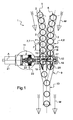
- FIG.1 there is shown a cap feeding unit 1 as part of a container handling machine in which molded containers are rinsed, filled and then capped.
- Caps 2 are put in bulk in at least one hopper (not shown), for example of the rotating/vibrating plate type, standing on top of a machine frame.
- Caps 2 are fed from the hoppers into at least two cap feeding lines, e.g. one first cap feeding line 3 receiving a first row 5 of caps 2, and at least one second cap feeding line 4 receiving a second row 6 of caps 2. All caps 2 of a same row have their concavity oriented in the same way, preferably upwardly with respect of the machine frame.
- the cap feeding lines 3, 4 may be connected to a common hopper, or to different hoppers.
- the cap feeding lines 3, 4 are preferably formed of stainless steel wire guides.
- the cap feeding lines 3, 4 have a horizontal portion which, depending upon the machine speed rate and/or capacity, may run all or partly along the machine frame, either longitudinally or transversely. In the vicinity of a machine frame edge, cap feeding lines 3, 4 each have a bend and, downstream the bend, a vertical portion 7, 8 wherein the concavity of the caps 2 is oriented outwardly with respect of the machine frame.
- the vertical portions 7, 8 of the feeding lines 3, 4 run parallel to each other before they merge at a Y-shaped junction area 9 into one single cap feeding line 10, in which caps 2 coming alternately from the first and second feeding lines 3, 4 are fed to a capping unit (not shown), where caps 2 are put on the mouths of the containers and screwed thereto.
- movement of the caps 2 is indicated by arrows M .
- the linear pitch P between two adjacent caps 2, i.e. the distance between their central axis along the row 5, 6, is equal to their external diameter.
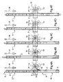
- Cap feeding unit 1 further comprises a rotary drive unit 11 positioned in the vicinity of the junction area 9. More precisely, rotary drive unit 11 is positioned immediately upstream the junction area 9, at the end of the vertical parallel portions 7, 8 of the feeding lines 3, 4.
- Rotary drive unit 11 is provided with a bracket 12 fastened to the cap feeding lines 3, 4 and comprises a pair of star wheels 13, 14 which are pivotally mounted on the bracket 12 so as to rotate around a horizontal axis A perpendicular to the moving direction M of the caps 2.
- the rotary drive unit 11 comprises:
- Each star wheel 13, 14 extends and rotates in a symmetry plane P1, P2 of the corresponding row 5, 6 of caps 2. Both star wheels 13, 14 are fixed to a common hub 17, fixed in turn to a driven rotary shaft 18, so the star wheels 13, 14 rotate simultaneously at the same speed.
- each star wheel 13, 14 the curvilinear distance - i.e. the distance measured along the periphery of the star wheel 13, 14 - between radial ends of two adjacent arms 15, 16 is substantially equal to the linear pitch P of the corresponding row 5, 6 of caps 2, so that the star wheel 13, 14 and the corresponding row 5, 6 of caps 2 mesh as a rack-and-pinion gear.
- each star wheel 13, 14 has eight arms 15, 16 (i.e. the angular pitch is 45°) and has a diameter which is substantially equal to 3 ⁇ P.
- the second star wheel 14 is positioned with an angular shift with respect of the first star wheel 13, equal to half the angular pitch between the arms 15, 16 (22,5° in the depicted example), whereby the second row 6 of caps 2 is vertically shifted of half the linear pitch P with respect of the first row 5, and the caps 2 of the first row 5 and second row 6 are alternately chucked, across the Y-shaped junction area 9, to the single downstream feeding line 10.
- the rotary speed of the star wheels 13, 14 is set to such a value that the linear speed of the radial ends of the arms 15, 16 is substantially equal to the linear speed of the caps 2 as if they were freely falling along the vertical portions 7, 8 of the feeding lines 3, 4, so that the caps 2 are not slew down due to the presence of the star wheels 13, 14.
- the cap feeding unit 1 is provided with at least a pair of air nozzles 19, 20 which are directed both toward the concave portion of the caps 2 and downward, immediately downstream the star wheels 13, 14, in order to accelerate the caps 2 in the junction area 9.
- the rotary drive unit 1 further comprises a motor 21, a driving shaft 22 coupled to the motor 21, and a clutch 23 which couples the driving shaft 22 to the driven shaft 18.
- the clutch 23, of the magnetic type comprises a first clutch disc 24 fixed to the driving shaft 22 and including a first annular set 25 of permanent magnets, and a second clutch disc 26 fixed to the driven shaft 18 and including a second annular set 27 of permanent magnets facing the first annular set 25 of permanent magnets.
- the driven shaft 18 is pivotally coupled to the driving shaft 22, so that the motor 21 rotates the driven shaft 18 - and therefore the star wheels 13, 14 - at a predetermined angular speed, as long as no resistant torque applies to at least one star wheel 13, 14 or, in case such a resistant torque applies, until this resistant torque is lower than a maximum clutch coupling torque.
- FIG.4B One arm 15 may then hit the edge of a cap 2 of the next coming row, as depicted on FIG.4C .
- the corresponding star wheel 13 is blocked in rotation as the resistant torque exerted by the cap 2 is greater than the maximum clutch coupling torque.
- the driven shaft 18 is then uncoupled from the driving shaft 22 and, in reaction to the hit, the star wheel 13 is shifted back over a small angle ( FIG.4D ), thereby allowing the cap 2 to move forward.
- FIG.4E After a fraction of a second, the driven shaft 18 is coupled back to the driving shaft 22, and the star wheel 13 can engage the corresponding row 5 of caps 2 again.
- the rotary drive unit 1 is provided with means for setting the maximum clutch coupling torque by setting the distance between the annular sets 25, 27 of magnets.
- these setting means are means for moving the second clutch disc 26 along the rotary axis A of the driven shaft 18.
- the second clutch disc 26 is screwed onto a threaded end portion 28 of the driven shaft 18, which is provided with an elongated hole 29.
- a coupling pin 30 is inserted through both the second clutch disc 26 and the elongated hole 29 in the driven shaft 18, thereby preventing any rotation therebetween. Setting the position of the second clutch disc 29 along the driven shaft 18 is achieved by removing the coupling pin 30, screwing - or unscrewing - the clutch disc 26 and, once reached the desired position, putting the coupling pin 30 back in position.
Landscapes
- Engineering & Computer Science (AREA)
- Mechanical Engineering (AREA)
- Specific Conveyance Elements (AREA)
- Sealing Of Jars (AREA)
- Dental Tools And Instruments Or Auxiliary Dental Instruments (AREA)
Claims (7)
- Unité d'alimentation en capuchons (1) comprenant :- une première chaîne d'alimentation en capuchons (3) recevant une première rangée de capuchons (2),- au moins une deuxième chaîne d'alimentation en capuchons (4) recevant une deuxième rangée de capuchons (2),- lesdites première et deuxième chaînes d'alimentation en capuchons (3, 4) fusionnant à une zone de jonction (9) pour former une seule chaîne d'alimentation en capuchons (10),- ladite unité d'alimentation en capuchons (1) étant caractérisée en ce qu'elle comprend en outre une unité d'entraînement de type rotatif (11) positionnée à proximité de la zone de jonction (9) et comprenant :- une première roue en étoile (13) comprenant une pluralité de bras s'étendant radialement (15) qui sont mis en engagement avec la première rangée de capuchons (2),- au moins une deuxième roue en étoile (14) comprenant une pluralité de bras s'étendant radialement (16) qui sont mis en engagement avec la deuxième rangée de capuchons (2) ladite deuxième roue en étoile étant positionnée avec un décalage angulaire par rapport à la première roue en étoile (13).
- Unité d'alimentation en capuchons (1) selon la revendication 1, ledit décalage angulaire étant égal au pas angulaire entre les bras (15, 16).
- Unité d'alimentation en capuchons (1) selon la revendication 1 ou 2, la distance entre les extrémités radiales de deux bras adjacents (15, 16) étant sensiblement égale au pas linéaire des rangées (5, 6) de capuchons.
- Unité d'alimentation en capuchons (1) selon l'une quelconque des revendications 1-3, l'unité d'entraînement de type rotatif (11) comprenant un arbre rotatif mené (18) sur lequel les roues en étoile (13, 14) sont montées.
- Unité d'alimentation en capuchons (1) selon la revendication 4, l'unité d'entraînement rotative (11) comprenant :- un moteur (21),- un arbre menant (22) couplé au moteur (21),- un embrayage (23) qui couple l'arbre menant (22) à l'arbre mené (18).
- Unité d'alimentation en capuchons (1) selon la revendication 5, ledit embrayage (23) comprenant:- un premier disque d'embrayage (24), fixé à l'arbre menant (22), ledit premier disque d'embrayage (24), comprenant un premier ensemble annulaire (25) d'aimants permanents,- un deuxième disque d'embrayage (26), fixé à l'arbre mené (18), ledit deuxième disque d'embrayage (26), comprenant un deuxième ensemble annulaire (27) d'aimants permanents positionné face audit premier ensemble annulaire (25) d'aimants permanents.
- Unité d'alimentation en capuchons (1) selon la revendication 6, ladite l'unité d'entraînement rotative (11) comprenant des moyens (28, 29, 30) servant à déplacer ledit deuxième disque d'embrayage (26) le long de l'axe rotatif (A) de l'arbre mené (18).
Applications Claiming Priority (1)
| Application Number | Priority Date | Filing Date | Title |
|---|---|---|---|
| PCT/IB2007/002104 WO2008125898A1 (fr) | 2007-04-11 | 2007-04-11 | Unité d'alimentation en capuchons ayant des roues en étoile décalées |
Publications (2)
| Publication Number | Publication Date |
|---|---|
| EP2134635A1 EP2134635A1 (fr) | 2009-12-23 |
| EP2134635B1 true EP2134635B1 (fr) | 2011-02-23 |
Family
ID=38986741
Family Applications (1)
| Application Number | Title | Priority Date | Filing Date |
|---|---|---|---|
| EP07789542A Not-in-force EP2134635B1 (fr) | 2007-04-11 | 2007-04-11 | Unité d'alimentation en capuchons ayant des roues en étoile décalées |
Country Status (8)
| Country | Link |
|---|---|
| EP (1) | EP2134635B1 (fr) |
| JP (1) | JP2010523423A (fr) |
| CN (1) | CN101678965B (fr) |
| AT (1) | ATE499316T1 (fr) |
| DE (1) | DE602007012772D1 (fr) |
| ES (1) | ES2364656T3 (fr) |
| MX (1) | MX2009010832A (fr) |
| WO (1) | WO2008125898A1 (fr) |
Families Citing this family (5)
| Publication number | Priority date | Publication date | Assignee | Title |
|---|---|---|---|---|
| DE102010049135A1 (de) | 2010-10-22 | 2012-04-26 | Krones Aktiengesellschaft | Vorrichtung und Verfahren zum Transportieren von Behältnisverschlüssen |
| JP6022931B2 (ja) * | 2012-12-27 | 2016-11-09 | 三機工業株式会社 | 合流装置 |
| CN107089503A (zh) * | 2017-05-26 | 2017-08-25 | 哈尔滨理工大学 | 一种可调式圆柱类工件输送装置 |
| DE102021127329A1 (de) * | 2021-10-21 | 2023-04-27 | Krones Aktiengesellschaft | Vorrichtung zur Zufuhr von Verschlüssen an einen Verschließer in einer Getränkeabfüllanlage |
| CN116354080A (zh) * | 2023-03-24 | 2023-06-30 | 安徽企铭智能制造有限公司 | 一种球笼上料加工的载盘 |
Family Cites Families (6)
| Publication number | Priority date | Publication date | Assignee | Title |
|---|---|---|---|---|
| IT1277135B1 (it) * | 1995-01-05 | 1997-11-04 | Mauro Lenzi | Dispositivo per l espulsione automatica da un condotto di alimentazione di capsule, tappi o elementi generalmente concavi, di |
| DE19522036A1 (de) * | 1995-06-17 | 1996-12-19 | Getraenkemaschinen Und Behaelt | Vorrichtung zum Herstellen sowie zum Zuführen von Verschlußkappen aus Aluminium zu Verschließorganen an Verschließmaschinen für Gefäße |
| JP3904125B2 (ja) * | 1998-02-27 | 2007-04-11 | 澁谷工業株式会社 | キャッパ |
| JP2003128238A (ja) * | 2001-10-26 | 2003-05-08 | F I T:Kk | ワーク合流装置 |
| CN2666860Y (zh) * | 2003-11-19 | 2004-12-29 | 郑俊岭 | 齿盘式送料器用的气吸式靠料装置 |
| JP2005247444A (ja) * | 2004-03-01 | 2005-09-15 | Mitsubishi Materials Techno Corp | 単列合流エアフロー装置 |
-
2007
- 2007-04-11 DE DE602007012772T patent/DE602007012772D1/de active Active
- 2007-04-11 JP JP2010502599A patent/JP2010523423A/ja not_active Ceased
- 2007-04-11 EP EP07789542A patent/EP2134635B1/fr not_active Not-in-force
- 2007-04-11 ES ES07789542T patent/ES2364656T3/es active Active
- 2007-04-11 WO PCT/IB2007/002104 patent/WO2008125898A1/fr not_active Ceased
- 2007-04-11 CN CN200780052987.XA patent/CN101678965B/zh not_active Expired - Fee Related
- 2007-04-11 MX MX2009010832A patent/MX2009010832A/es active IP Right Grant
- 2007-04-11 AT AT07789542T patent/ATE499316T1/de not_active IP Right Cessation
Also Published As
| Publication number | Publication date |
|---|---|
| MX2009010832A (es) | 2010-01-15 |
| WO2008125898A1 (fr) | 2008-10-23 |
| EP2134635A1 (fr) | 2009-12-23 |
| ATE499316T1 (de) | 2011-03-15 |
| ES2364656T3 (es) | 2011-09-08 |
| CN101678965A (zh) | 2010-03-24 |
| DE602007012772D1 (de) | 2011-04-07 |
| JP2010523423A (ja) | 2010-07-15 |
| CN101678965B (zh) | 2014-08-13 |
Similar Documents
| Publication | Publication Date | Title |
|---|---|---|
| EP2134635B1 (fr) | Unité d'alimentation en capuchons ayant des roues en étoile décalées | |
| EP2139796B1 (fr) | Dispositif de transfert de contenant ayant un element de guidage de transfert | |
| CN101489909B (zh) | 用于瓶类容器的处理机 | |
| US8794425B2 (en) | Device for gripping PET bottles in bottle-filling systems or the like | |
| CN219688554U (zh) | 运输装置 | |
| EP1801066B1 (fr) | Dispositif d'alimentation de capsules | |
| EP2196417B1 (fr) | Dispositif pour orienter des objets, notamment des bouchons | |
| CN107601418A (zh) | 一种吹灌旋一体设备 | |
| JP5602853B2 (ja) | スクリューフィーダー装置 | |
| EP0302837A2 (fr) | Dispositif pour déterminer un nombre prédéterminé de récipients, imbriqués partiellement et formant un paquet de ces mêmes récipients | |
| US3643780A (en) | Automatic bottle feeder | |
| WO2011117897A1 (fr) | Procédé et système de rotation d'un groupe de contenants | |
| US7293639B2 (en) | Case rotating system | |
| US20120175221A1 (en) | High Speed Diverter | |
| EP1260467A1 (fr) | Dispositif d' orientation et de déviation d' un paquet sur un convoyeur | |
| JP4317974B2 (ja) | ロータリーストッパ | |
| CN103738900B (zh) | 一种进瓶螺杆卡瓶、堵瓶保护机构 | |
| EP0826613B1 (fr) | Méthode et dispositif pour orienter les capuchons pour pulvérisateurs | |
| JP5453700B2 (ja) | 物品整列装置 | |
| CN101959775A (zh) | 具有可移动的封盖推动器的封盖传送单元 | |
| US7392111B2 (en) | Rotary desiccant feeder method and apparatus | |
| US11505412B2 (en) | Device for selecting and discarding pucks in apparatus for coupling such pucks together with bottles to be filled | |
| WO2026073550A1 (fr) | Roue de sortie à double roue collectrice pour machine d'emballage | |
| CN203715241U (zh) | 一种进瓶螺杆卡瓶、堵瓶保护机构 | |
| CN104648977A (zh) | 一种输送装置 |
Legal Events
| Date | Code | Title | Description |
|---|---|---|---|
| PUAI | Public reference made under article 153(3) epc to a published international application that has entered the european phase |
Free format text: ORIGINAL CODE: 0009012 |
|
| 17P | Request for examination filed |
Effective date: 20091002 |
|
| AK | Designated contracting states |
Kind code of ref document: A1 Designated state(s): AT BE BG CH CY CZ DE DK EE ES FI FR GB GR HU IE IS IT LI LT LU LV MC MT NL PL PT RO SE SI SK TR |
|
| DAX | Request for extension of the european patent (deleted) | ||
| GRAP | Despatch of communication of intention to grant a patent |
Free format text: ORIGINAL CODE: EPIDOSNIGR1 |
|
| GRAS | Grant fee paid |
Free format text: ORIGINAL CODE: EPIDOSNIGR3 |
|
| GRAA | (expected) grant |
Free format text: ORIGINAL CODE: 0009210 |
|
| AK | Designated contracting states |
Kind code of ref document: B1 Designated state(s): AT BE BG CH CY CZ DE DK EE ES FI FR GB GR HU IE IS IT LI LT LU LV MC MT NL PL PT RO SE SI SK TR |
|
| REG | Reference to a national code |
Ref country code: GB Ref legal event code: FG4D |
|
| REG | Reference to a national code |
Ref country code: CH Ref legal event code: EP |
|
| REG | Reference to a national code |
Ref country code: IE Ref legal event code: FG4D |
|
| REF | Corresponds to: |
Ref document number: 602007012772 Country of ref document: DE Date of ref document: 20110407 Kind code of ref document: P |
|
| REG | Reference to a national code |
Ref country code: DE Ref legal event code: R096 Ref document number: 602007012772 Country of ref document: DE Effective date: 20110407 |
|
| REG | Reference to a national code |
Ref country code: NL Ref legal event code: VDEP Effective date: 20110223 |
|
| LTIE | Lt: invalidation of european patent or patent extension |
Effective date: 20110223 |
|
| PG25 | Lapsed in a contracting state [announced via postgrant information from national office to epo] |
Ref country code: LV Free format text: LAPSE BECAUSE OF FAILURE TO SUBMIT A TRANSLATION OF THE DESCRIPTION OR TO PAY THE FEE WITHIN THE PRESCRIBED TIME-LIMIT Effective date: 20110223 Ref country code: SE Free format text: LAPSE BECAUSE OF FAILURE TO SUBMIT A TRANSLATION OF THE DESCRIPTION OR TO PAY THE FEE WITHIN THE PRESCRIBED TIME-LIMIT Effective date: 20110223 Ref country code: PT Free format text: LAPSE BECAUSE OF FAILURE TO SUBMIT A TRANSLATION OF THE DESCRIPTION OR TO PAY THE FEE WITHIN THE PRESCRIBED TIME-LIMIT Effective date: 20110623 Ref country code: LT Free format text: LAPSE BECAUSE OF FAILURE TO SUBMIT A TRANSLATION OF THE DESCRIPTION OR TO PAY THE FEE WITHIN THE PRESCRIBED TIME-LIMIT Effective date: 20110223 Ref country code: GR Free format text: LAPSE BECAUSE OF FAILURE TO SUBMIT A TRANSLATION OF THE DESCRIPTION OR TO PAY THE FEE WITHIN THE PRESCRIBED TIME-LIMIT Effective date: 20110524 |
|
| PG25 | Lapsed in a contracting state [announced via postgrant information from national office to epo] |
Ref country code: SI Free format text: LAPSE BECAUSE OF FAILURE TO SUBMIT A TRANSLATION OF THE DESCRIPTION OR TO PAY THE FEE WITHIN THE PRESCRIBED TIME-LIMIT Effective date: 20110223 Ref country code: FI Free format text: LAPSE BECAUSE OF FAILURE TO SUBMIT A TRANSLATION OF THE DESCRIPTION OR TO PAY THE FEE WITHIN THE PRESCRIBED TIME-LIMIT Effective date: 20110223 Ref country code: NL Free format text: LAPSE BECAUSE OF FAILURE TO SUBMIT A TRANSLATION OF THE DESCRIPTION OR TO PAY THE FEE WITHIN THE PRESCRIBED TIME-LIMIT Effective date: 20110223 Ref country code: AT Free format text: LAPSE BECAUSE OF FAILURE TO SUBMIT A TRANSLATION OF THE DESCRIPTION OR TO PAY THE FEE WITHIN THE PRESCRIBED TIME-LIMIT Effective date: 20110223 Ref country code: CY Free format text: LAPSE BECAUSE OF FAILURE TO SUBMIT A TRANSLATION OF THE DESCRIPTION OR TO PAY THE FEE WITHIN THE PRESCRIBED TIME-LIMIT Effective date: 20110223 Ref country code: BG Free format text: LAPSE BECAUSE OF FAILURE TO SUBMIT A TRANSLATION OF THE DESCRIPTION OR TO PAY THE FEE WITHIN THE PRESCRIBED TIME-LIMIT Effective date: 20110523 Ref country code: BE Free format text: LAPSE BECAUSE OF FAILURE TO SUBMIT A TRANSLATION OF THE DESCRIPTION OR TO PAY THE FEE WITHIN THE PRESCRIBED TIME-LIMIT Effective date: 20110223 |
|
| REG | Reference to a national code |
Ref country code: ES Ref legal event code: FG2A Ref document number: 2364656 Country of ref document: ES Kind code of ref document: T3 Effective date: 20110908 |
|
| PG25 | Lapsed in a contracting state [announced via postgrant information from national office to epo] |
Ref country code: EE Free format text: LAPSE BECAUSE OF FAILURE TO SUBMIT A TRANSLATION OF THE DESCRIPTION OR TO PAY THE FEE WITHIN THE PRESCRIBED TIME-LIMIT Effective date: 20110223 Ref country code: DK Free format text: LAPSE BECAUSE OF FAILURE TO SUBMIT A TRANSLATION OF THE DESCRIPTION OR TO PAY THE FEE WITHIN THE PRESCRIBED TIME-LIMIT Effective date: 20110223 |
|
| PG25 | Lapsed in a contracting state [announced via postgrant information from national office to epo] |
Ref country code: RO Free format text: LAPSE BECAUSE OF FAILURE TO SUBMIT A TRANSLATION OF THE DESCRIPTION OR TO PAY THE FEE WITHIN THE PRESCRIBED TIME-LIMIT Effective date: 20110223 Ref country code: SK Free format text: LAPSE BECAUSE OF FAILURE TO SUBMIT A TRANSLATION OF THE DESCRIPTION OR TO PAY THE FEE WITHIN THE PRESCRIBED TIME-LIMIT Effective date: 20110223 Ref country code: MC Free format text: LAPSE BECAUSE OF NON-PAYMENT OF DUE FEES Effective date: 20110430 Ref country code: CZ Free format text: LAPSE BECAUSE OF FAILURE TO SUBMIT A TRANSLATION OF THE DESCRIPTION OR TO PAY THE FEE WITHIN THE PRESCRIBED TIME-LIMIT Effective date: 20110223 |
|
| REG | Reference to a national code |
Ref country code: CH Ref legal event code: PL |
|
| PG25 | Lapsed in a contracting state [announced via postgrant information from national office to epo] |
Ref country code: MT Free format text: LAPSE BECAUSE OF FAILURE TO SUBMIT A TRANSLATION OF THE DESCRIPTION OR TO PAY THE FEE WITHIN THE PRESCRIBED TIME-LIMIT Effective date: 20110223 |
|
| PLBE | No opposition filed within time limit |
Free format text: ORIGINAL CODE: 0009261 |
|
| STAA | Information on the status of an ep patent application or granted ep patent |
Free format text: STATUS: NO OPPOSITION FILED WITHIN TIME LIMIT |
|
| GBPC | Gb: european patent ceased through non-payment of renewal fee |
Effective date: 20110523 |
|
| PG25 | Lapsed in a contracting state [announced via postgrant information from national office to epo] |
Ref country code: LI Free format text: LAPSE BECAUSE OF NON-PAYMENT OF DUE FEES Effective date: 20110430 Ref country code: CH Free format text: LAPSE BECAUSE OF NON-PAYMENT OF DUE FEES Effective date: 20110430 |
|
| 26N | No opposition filed |
Effective date: 20111124 |
|
| REG | Reference to a national code |
Ref country code: IE Ref legal event code: MM4A |
|
| PG25 | Lapsed in a contracting state [announced via postgrant information from national office to epo] |
Ref country code: PL Free format text: LAPSE BECAUSE OF FAILURE TO SUBMIT A TRANSLATION OF THE DESCRIPTION OR TO PAY THE FEE WITHIN THE PRESCRIBED TIME-LIMIT Effective date: 20110223 |
|
| REG | Reference to a national code |
Ref country code: DE Ref legal event code: R097 Ref document number: 602007012772 Country of ref document: DE Effective date: 20111124 |
|
| PG25 | Lapsed in a contracting state [announced via postgrant information from national office to epo] |
Ref country code: IE Free format text: LAPSE BECAUSE OF NON-PAYMENT OF DUE FEES Effective date: 20110411 |
|
| PG25 | Lapsed in a contracting state [announced via postgrant information from national office to epo] |
Ref country code: GB Free format text: LAPSE BECAUSE OF NON-PAYMENT OF DUE FEES Effective date: 20110523 |
|
| PG25 | Lapsed in a contracting state [announced via postgrant information from national office to epo] |
Ref country code: LU Free format text: LAPSE BECAUSE OF NON-PAYMENT OF DUE FEES Effective date: 20110411 |
|
| PG25 | Lapsed in a contracting state [announced via postgrant information from national office to epo] |
Ref country code: IS Free format text: LAPSE BECAUSE OF FAILURE TO SUBMIT A TRANSLATION OF THE DESCRIPTION OR TO PAY THE FEE WITHIN THE PRESCRIBED TIME-LIMIT Effective date: 20110223 |
|
| PG25 | Lapsed in a contracting state [announced via postgrant information from national office to epo] |
Ref country code: TR Free format text: LAPSE BECAUSE OF FAILURE TO SUBMIT A TRANSLATION OF THE DESCRIPTION OR TO PAY THE FEE WITHIN THE PRESCRIBED TIME-LIMIT Effective date: 20110223 |
|
| PG25 | Lapsed in a contracting state [announced via postgrant information from national office to epo] |
Ref country code: HU Free format text: LAPSE BECAUSE OF FAILURE TO SUBMIT A TRANSLATION OF THE DESCRIPTION OR TO PAY THE FEE WITHIN THE PRESCRIBED TIME-LIMIT Effective date: 20110223 |
|
| REG | Reference to a national code |
Ref country code: FR Ref legal event code: PLFP Year of fee payment: 10 |
|
| PGFP | Annual fee paid to national office [announced via postgrant information from national office to epo] |
Ref country code: ES Payment date: 20160407 Year of fee payment: 10 |
|
| REG | Reference to a national code |
Ref country code: FR Ref legal event code: PLFP Year of fee payment: 11 |
|
| REG | Reference to a national code |
Ref country code: FR Ref legal event code: PLFP Year of fee payment: 12 |
|
| REG | Reference to a national code |
Ref country code: ES Ref legal event code: FD2A Effective date: 20180705 |
|
| PG25 | Lapsed in a contracting state [announced via postgrant information from national office to epo] |
Ref country code: ES Free format text: LAPSE BECAUSE OF NON-PAYMENT OF DUE FEES Effective date: 20170412 |
|
| PGFP | Annual fee paid to national office [announced via postgrant information from national office to epo] |
Ref country code: FR Payment date: 20200319 Year of fee payment: 14 |
|
| PGFP | Annual fee paid to national office [announced via postgrant information from national office to epo] |
Ref country code: DE Payment date: 20200319 Year of fee payment: 14 |
|
| PGFP | Annual fee paid to national office [announced via postgrant information from national office to epo] |
Ref country code: IT Payment date: 20200318 Year of fee payment: 14 |
|
| REG | Reference to a national code |
Ref country code: DE Ref legal event code: R119 Ref document number: 602007012772 Country of ref document: DE |
|
| PG25 | Lapsed in a contracting state [announced via postgrant information from national office to epo] |
Ref country code: FR Free format text: LAPSE BECAUSE OF NON-PAYMENT OF DUE FEES Effective date: 20210430 Ref country code: DE Free format text: LAPSE BECAUSE OF NON-PAYMENT OF DUE FEES Effective date: 20211103 |
|
| PG25 | Lapsed in a contracting state [announced via postgrant information from national office to epo] |
Ref country code: IT Free format text: LAPSE BECAUSE OF NON-PAYMENT OF DUE FEES Effective date: 20200411 |
|
| PG25 | Lapsed in a contracting state [announced via postgrant information from national office to epo] |
Ref country code: IT Free format text: LAPSE BECAUSE OF NON-PAYMENT OF DUE FEES Effective date: 20210411 |