EP2133171A1 - Dispositif mécanique de traitement de pièces à usiner à l'aide d'un rayon laser - Google Patents
Dispositif mécanique de traitement de pièces à usiner à l'aide d'un rayon laser Download PDFInfo
- Publication number
- EP2133171A1 EP2133171A1 EP08010660A EP08010660A EP2133171A1 EP 2133171 A1 EP2133171 A1 EP 2133171A1 EP 08010660 A EP08010660 A EP 08010660A EP 08010660 A EP08010660 A EP 08010660A EP 2133171 A1 EP2133171 A1 EP 2133171A1
- Authority
- EP
- European Patent Office
- Prior art keywords
- optics
- axis
- collimating
- laser beam
- focusing optics
- Prior art date
- Legal status (The legal status is an assumption and is not a legal conclusion. Google has not performed a legal analysis and makes no representation as to the accuracy of the status listed.)
- Granted
Links
Images

Classifications
-
- B—PERFORMING OPERATIONS; TRANSPORTING
- B23—MACHINE TOOLS; METAL-WORKING NOT OTHERWISE PROVIDED FOR
- B23K—SOLDERING OR UNSOLDERING; WELDING; CLADDING OR PLATING BY SOLDERING OR WELDING; CUTTING BY APPLYING HEAT LOCALLY, e.g. FLAME CUTTING; WORKING BY LASER BEAM
- B23K26/00—Working by laser beam, e.g. welding, cutting or boring
- B23K26/02—Positioning or observing the workpiece, e.g. with respect to the point of impact; Aligning, aiming or focusing the laser beam
- B23K26/06—Shaping the laser beam, e.g. by masks or multi-focusing
-
- B—PERFORMING OPERATIONS; TRANSPORTING
- B23—MACHINE TOOLS; METAL-WORKING NOT OTHERWISE PROVIDED FOR
- B23K—SOLDERING OR UNSOLDERING; WELDING; CLADDING OR PLATING BY SOLDERING OR WELDING; CUTTING BY APPLYING HEAT LOCALLY, e.g. FLAME CUTTING; WORKING BY LASER BEAM
- B23K26/00—Working by laser beam, e.g. welding, cutting or boring
- B23K26/36—Removing material
- B23K26/38—Removing material by boring or cutting
Definitions
- the collimation device is aligned such that the device axis runs in the transverse direction of the z-axis, ie in the transverse direction of the axis of the machining beam directed from the machining head to be processed.
- the collimation device can protrude transversely to the z-axis.
- the collimation device can have a considerable length in the direction of the device axis.
- the processing head of the device according to the invention is decoupled from the collimation device in the case of feed movements in the direction of the z-axis.
- Decoupling ie the movability of the machining head relative to the collimation device, allows a compact construction of the assembly comprising the machining head and the collimation device, without having to accept limitations in the performance of the machine device.
- inventive decoupling of machining head and Kollimations noticed during feed movements of the machining head in cases where the collimation has a motorized actuator for the collimating optics and consequently has a correspondingly large mass to move in rigid coupling of collimation and machining head jointly with the machining head would.
- the collimation device is fixed in the direction of the z-axis in a preferred embodiment of the invention. Accordingly, movements in this direction are performed exclusively by the machining head.
- the Erfindungsbauart according to claim 3 Due to a particularly small overall height in the direction of the z-axis with simultaneous simple laser beam guidance between the collimating optics and the focusing optics, the Erfindungsbauart according to claim 3, in the case of which the bamboosachse the Kollimations adopted at a right angle to the z-axis. Deviating from a right angle angles are also conceivable.
- the claims 4 to 8 relate to measures that are taken in development of the invention, regardless of the relative mobility of the machining head and collimation in the direction of the z-axis to ensure trouble-free, efficient and high-quality laser processing.
- the laser beam extends between the collimating optics and the focusing optics in a beam guiding space bounded by a room wall.
- the space wall of the beam guiding space is variable in length in the direction of the z-axis in accordance with the movements made by the machining head. Inside the beam guiding space, the laser beam is protected against damaging environmental influences.
- the beam guiding space of the device according to the invention has, according to claim 5, a chamber wall which has proven itself many times in practice.
- the beam guiding space between the collimating optics and the focusing optics is filled with a gaseous medium and sealed substantially hermetically.
- the composition of the gaseous medium is tuned to the running in the beam guiding space laser beam and ensures that the laser beam is not affected in its decisive for the success of workpiece machining properties.
- the hermetic sealing of the beam guiding space serves to keep harmful environmental influences, in particular for the laser beam power, from the laser beam to harmful gases.
- the gas equalization volume according to the invention ensures that the internal pressure of the jet guidance chamber remains largely constant regardless of the feed movements performed by the processing head.
- Contaminations that have undesirably entered the beam guiding space between the collimating optics and the focusing optics are, in the case of the type of invention according to claim 8, bound by a dirt absorber provided in the interior of the beam guiding space and thereby kept away from the laser beam.
- Absorber films for example, are commonly used as dirt absorbers.
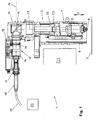
- the laser cutting machine 1 is a flatbed machine, which as such comprises a movement unit 2 in the usual way, which can be moved via a workpiece support 3 indicated in the figures.
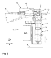
- the main component of the movement unit 2 is a bridge 4, which is likewise shown only schematically in the figures, which spans the workpiece support 3 and moves relative to the stationary workpiece support 3 in the direction of a horizontal x-axis (FIG. FIG. 2 ) can be moved.
- the bridge 4 supports and in turn leads to an assembly 5. This can be moved along the bridge 4 in the direction of a horizontal y-axis (FIG. FIG. 2 ).
- the assembly 5 comprises a carriage 6, which is guided on the bridge 4 in the direction of the y-axis and movable by means of the aforementioned linear drive.
- the carriage 6 in turn supports a machining head in the form of a laser cutting head 7.
- the laser cutting head 7 is movable or deliverable on the carriage 6 in the direction of a vertical z-axis.
- a feed drive for the laser cutting head 7 is a not shown linear drive. Alternatively, for example, a belt drive is conceivable.
- a conventional cutting nozzle 8 At the side facing the workpiece support 3 side of the laser cutting head 7 is provided with a conventional cutting nozzle 8.
- a focus lens designed as a focusing lens 9 of conventional design is housed.
- a deflection housing 10 which receives a deflection optics in the form of a deflection mirror 11.
- a collimation 12 is flanged.
- a device axis 13 of the collimation device 12 extends horizontally and thus perpendicular to the z-axis.
- Essential components of the collimation device 12 are a collimating optics in the form of a collimating lens 14 and an actuator 15, which is designed as a spindle drive and by means of which the collimating lens 14 can be delivered in the direction of the device axis 13. Both the actuator 15 and the collimating lens 14 are housed inside a Kollimationsgephases 16.
- the collimation housing 16 is provided with a connector receptacle 17.
- a cable connector 18 is inserted, which in turn is attached to the collimating device 12 towards the end of a laser light cable 19.
- the laser light cable 19 provides a connection of the assembly 5 with a beam source in the form of an in FIG. 1 indicated solid state laser 20 ago. This generates a laser beam, which is fed in the usual way in the laser light cable 19 and fed through the laser light cable 19 of the assembly 5. In the region of the assembly 5, the laser beam is shown in the figures in the form of a beam axis 21.
- the device axis 13 of the collimation device 12 coincides in the example shown with the axis of the laser beam 21, which passes through the collimating lens 14. Is in place of the collimating lens 14 provided a mirror arrangement, the device axis 13 is defined by the direction (main direction), in which the connection of the entry point and exit point of the laser beam 21 runs on the collimating optics.
- the laser beam 21 is aligned in parallel by means of the collimation device 12.
- the collimating lens 14 of the collimation device 12 is penetrated by the laser beam 21 along the device axis 13.
- the laser beam 21 is deflected by means of the deflection mirror 11 by 90 ° to the focusing lens 9 out.
- the deflection optics or the deflecting mirror 11 can be tiltable or pivotable, so that the laser beam 21 incident on it or on it can in each case be aligned parallel to the z axis.
- the focusing lens 9 generates the laser cutting beam, which ultimately serves as a machining tool, from the laser beam 21, which until then was the raw beam. From the focusing lens 9 of the laser cutting beam is directed to the respective processed, deposited on the workpiece support 3 sheet. All essential functions of the laser cutting machine 1 are numerically controlled.
- the laser beam 21 extends in a beam guiding space 22, the space wall of which is formed by a conventional bellows 23.
- the bellows 23 is connected with one longitudinal end to the deflection housing 10 and with the other longitudinal end of the laser cutting head 7. It can be pulled out and compressed in the direction of the z-axis.
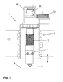
- the jet guiding space 22 is filled in the example shown with purified air and hermetically sealed as far as possible against the environment of the assembly 5. About a flow channel not shown in detail the jet guiding space 22 is in fluid communication with a bellows-like gas compensation volume 24, which in detail in FIG FIG. 4 can be seen. In the FIGS. 1 to 3 the gas compensation volume 24 is largely covered by the deflection housing 10. In the interior of the beam guiding space 22 there is a pressure which slightly exceeds the ambient pressure.
- the laser beam 21 in the interior of the beam guiding space 22 is protected against damaging environmental influences, in particular against performance-reducing gases.
- Solid contaminants which reach the interior of the beam guiding space 22 regardless of the protective measures taken, are bound by a dirt absorber (not shown in detail) in the interior of the beam guiding space 22 and thereby kept away from the laser beam 21.
- the laser cutting head 7 is moved in the direction of the z-axis in a position in which the cutting nozzle 8 has a lying on the order of one millimeter distance from the surface of the sheet to be machined. With such a nozzle spacing results in optimal processing results.
- the laser cutting head 7 is raised in the direction of the z-axis, before it moves to the next processing point.
- the laser cutting head 7 is delivered in the direction of the z-axis, in order to maintain the initially set nozzle spacing from the sheet surface approximately at sheet thickness changes.
- the Infeed movements of the laser processing head 7 in the current cutting operation are highly dynamic.
- the required dynamics of the feed movements of the laser cutting head 7 is made possible by the movement-related decoupling of the laser cutting head 7 from the other components of the assembly 5.
- only the laser cutting head 7 moves in the direction of the z-axis during the feed movements.
- the collimation device 12 with the laser light cable 19 connected thereto is stationary in the direction of the z-axis.
- Vibrations of the collimation device 12, which due to the projecting of the collimation 12 perpendicular to the direction of the z-axis take a considerable extent and thus could lead to an impairment of the leadership of the laser beam 21 are avoided.
- the horizontal alignment of the collimation device 12 results in a compact construction of the entire assembly 5.
- the laser light cable 19 can be laid flat and therefore extend with a radius of curvature which is greater than the minimum radius required for laser light cables.
- FIGS. 1 and 2 is the laser cutting head 7 in its raised starting position.
- the Figures 3 and 4 is the laser cutting head 7 against the FIGS. 1 and 2 lowered to the workpiece support 3 out.
- the bellows 23 is compared to the proportions according to the FIGS. 1 and 2 elongated.
- the gas equalization volume 24 has compared with the FIGS. 1 and 2 reduced.
Priority Applications (2)
| Application Number | Priority Date | Filing Date | Title |
|---|---|---|---|
| EP08010660A EP2133171B1 (fr) | 2008-06-12 | 2008-06-12 | Dispositif mécanique de traitement de pièces à usiner à l'aide d'un rayon laser |
| US12/483,435 US8314361B2 (en) | 2008-06-12 | 2009-06-12 | Device for laser machining |
Applications Claiming Priority (1)
| Application Number | Priority Date | Filing Date | Title |
|---|---|---|---|
| EP08010660A EP2133171B1 (fr) | 2008-06-12 | 2008-06-12 | Dispositif mécanique de traitement de pièces à usiner à l'aide d'un rayon laser |
Publications (2)
| Publication Number | Publication Date |
|---|---|
| EP2133171A1 true EP2133171A1 (fr) | 2009-12-16 |
| EP2133171B1 EP2133171B1 (fr) | 2012-08-08 |
Family
ID=40010826
Family Applications (1)
| Application Number | Title | Priority Date | Filing Date |
|---|---|---|---|
| EP08010660A Not-in-force EP2133171B1 (fr) | 2008-06-12 | 2008-06-12 | Dispositif mécanique de traitement de pièces à usiner à l'aide d'un rayon laser |
Country Status (2)
| Country | Link |
|---|---|
| US (1) | US8314361B2 (fr) |
| EP (1) | EP2133171B1 (fr) |
Cited By (4)
| Publication number | Priority date | Publication date | Assignee | Title |
|---|---|---|---|---|
| CN102756224A (zh) * | 2011-04-29 | 2012-10-31 | 宁波市拓新焊接技术有限公司 | 波纹管焊接专用焊机 |
| CN106392338A (zh) * | 2016-10-09 | 2017-02-15 | 湖北工业大学 | 一种太阳能电池片废片切割装置 |
| CN110673354A (zh) * | 2019-10-16 | 2020-01-10 | 中国航空工业集团公司洛阳电光设备研究所 | 一种球形光窗相对于方位俯仰两扫描轴的位置度调校方法及系统 |
| DE102021123617A1 (de) | 2021-09-13 | 2023-03-16 | Precitec Gmbh & Co. Kg | Laserbearbeitungskopf mit Klebefalle |
Families Citing this family (18)
| Publication number | Priority date | Publication date | Assignee | Title |
|---|---|---|---|---|
| DE102010020732B4 (de) * | 2010-05-17 | 2013-10-10 | Rena Gmbh | Vorrichtung und Verfahren zum Ausrichten eines Laserkopfes sowie Multi-Laserblock für eine Produktionsanlage |
| EP2409808A1 (fr) * | 2010-07-22 | 2012-01-25 | Bystronic Laser AG | Machine de traitement au laser |
| US9289852B2 (en) | 2011-01-27 | 2016-03-22 | Bystronic Laser Ag | Laser processing machine, laser cutting machine, and method for adjusting a focused laser beam |
| WO2012101533A1 (fr) | 2011-01-27 | 2012-08-02 | Bystronic Laser Ag | Machine de traitement au laser, en particulier machine de coupe au laser, ainsi que procédé permettant de centrer un faisceau laser, en particulier un faisceau focalisé |
| CN102615424A (zh) * | 2011-12-31 | 2012-08-01 | 武汉金运激光股份有限公司 | 一种装有调焦装置的激光切割头及确定焦距的方法 |
| EP2883647B1 (fr) | 2013-12-12 | 2019-05-29 | Bystronic Laser AG | Procédé de configuration d'un dispositif d'usinage au laser |
| US20230271275A9 (en) * | 2014-02-26 | 2023-08-31 | Gerber Technology Llc | Cutting machinery laser system |
| CN107438495B (zh) | 2015-02-12 | 2021-02-05 | 格罗弗治公司 | 云控制激光制造 |
| US10509390B2 (en) | 2015-02-12 | 2019-12-17 | Glowforge Inc. | Safety and reliability guarantees for laser fabrication |
| WO2018098396A1 (fr) | 2016-11-25 | 2018-05-31 | Glowforge Inc. | Machine commandée numériquement par ordinateur multi-utilisateurs |
| WO2018098397A1 (fr) | 2016-11-25 | 2018-05-31 | Glowforge Inc. | Calibrage d'une machine à commande numérique par ordinateur |
| WO2018098398A1 (fr) | 2016-11-25 | 2018-05-31 | Glowforge Inc. | Composants optiques prédéfinis dans une machine commandée numériquement par ordinateur |
| WO2018098393A1 (fr) | 2016-11-25 | 2018-05-31 | Glowforge Inc. | Boîtier pour machine à commande numérique par ordinateur |
| WO2018098399A1 (fr) | 2016-11-25 | 2018-05-31 | Glowforge Inc. | Décélération commandé de composants mobiles dans une machine à commande numérique par ordinateur |
| CN110226137A (zh) | 2016-11-25 | 2019-09-10 | 格罗弗治公司 | 借助图像跟踪进行制造 |
| CA3082884A1 (fr) * | 2017-10-05 | 2019-04-11 | Mct Of Wisconsin, Inc. | Systeme laser de machine de coupe |
| US11740608B2 (en) | 2020-12-24 | 2023-08-29 | Glowforge, Inc | Computer numerically controlled fabrication using projected information |
| US11698622B2 (en) | 2021-03-09 | 2023-07-11 | Glowforge Inc. | Previews for computer numerically controlled fabrication |
Citations (6)
| Publication number | Priority date | Publication date | Assignee | Title |
|---|---|---|---|---|
| US4997250A (en) * | 1989-11-17 | 1991-03-05 | General Electric Company | Fiber output coupler with beam shaping optics for laser materials processing system |
| DE9407288U1 (de) * | 1994-05-02 | 1994-08-04 | Trumpf Gmbh & Co | Laserschneidmaschine mit Fokuslageneinstellung |
| US6501043B1 (en) | 1999-10-22 | 2002-12-31 | Medtronic, Inc. | Apparatus and method for laser welding of ribbons |
| US20030196993A1 (en) * | 2002-04-18 | 2003-10-23 | Applied Materials, Inc. | Thermal flux deposition by scanning |
| US20050150876A1 (en) * | 2003-12-18 | 2005-07-14 | Roberto Menin | Method and device for laser welding |
| EP1716963A1 (fr) * | 2005-04-26 | 2006-11-02 | Highyag Lasertechnologie GmbH | Optiques pour le le travail à distance au laser permettant la création d'un espace de travail 3D |
Family Cites Families (11)
| Publication number | Priority date | Publication date | Assignee | Title |
|---|---|---|---|---|
| US5109148A (en) * | 1990-01-26 | 1992-04-28 | Mitsubishi Denki Kabushiki Kaisha | Positioning device for a machining apparatus |
| JP2591371B2 (ja) * | 1991-07-03 | 1997-03-19 | 三菱電機株式会社 | レーザ加工装置 |
| JP2798530B2 (ja) * | 1991-07-26 | 1998-09-17 | 三菱電機株式会社 | レーザ加工機 |
| JPH06335883A (ja) * | 1993-05-27 | 1994-12-06 | Toyoda Mach Works Ltd | ロボット制御装置 |
| JP3633117B2 (ja) * | 1996-07-17 | 2005-03-30 | 三菱電機株式会社 | 光走査式レーザ加工機 |
| DE29714489U1 (de) * | 1997-08-13 | 1997-10-09 | Trumpf Gmbh & Co | Laserbearbeitungsmaschine mit Gasausgleichsvolumen |
| JPH11221692A (ja) * | 1998-02-04 | 1999-08-17 | Amada Eng Center Co Ltd | レーザ光誘導方法およびその方法を用いた三次元レーザ加工機 |
| JP4583652B2 (ja) * | 2001-04-18 | 2010-11-17 | 株式会社アマダ | レーザ加工機 |
| JP4358458B2 (ja) * | 2001-06-01 | 2009-11-04 | コマツNtc株式会社 | レーザ加工装置 |
| JP2003071584A (ja) * | 2001-08-30 | 2003-03-11 | Amada Co Ltd | レーザ加工機の光路保護蛇腹 |
| US20060157457A1 (en) * | 2004-12-08 | 2006-07-20 | Matsushita Electric Industrial Co., Ltd. | Hybrid laser processing method and hybrid laser torch used in the method |
-
2008
- 2008-06-12 EP EP08010660A patent/EP2133171B1/fr not_active Not-in-force
-
2009
- 2009-06-12 US US12/483,435 patent/US8314361B2/en not_active Expired - Fee Related
Patent Citations (6)
| Publication number | Priority date | Publication date | Assignee | Title |
|---|---|---|---|---|
| US4997250A (en) * | 1989-11-17 | 1991-03-05 | General Electric Company | Fiber output coupler with beam shaping optics for laser materials processing system |
| DE9407288U1 (de) * | 1994-05-02 | 1994-08-04 | Trumpf Gmbh & Co | Laserschneidmaschine mit Fokuslageneinstellung |
| US6501043B1 (en) | 1999-10-22 | 2002-12-31 | Medtronic, Inc. | Apparatus and method for laser welding of ribbons |
| US20030196993A1 (en) * | 2002-04-18 | 2003-10-23 | Applied Materials, Inc. | Thermal flux deposition by scanning |
| US20050150876A1 (en) * | 2003-12-18 | 2005-07-14 | Roberto Menin | Method and device for laser welding |
| EP1716963A1 (fr) * | 2005-04-26 | 2006-11-02 | Highyag Lasertechnologie GmbH | Optiques pour le le travail à distance au laser permettant la création d'un espace de travail 3D |
Cited By (4)
| Publication number | Priority date | Publication date | Assignee | Title |
|---|---|---|---|---|
| CN102756224A (zh) * | 2011-04-29 | 2012-10-31 | 宁波市拓新焊接技术有限公司 | 波纹管焊接专用焊机 |
| CN106392338A (zh) * | 2016-10-09 | 2017-02-15 | 湖北工业大学 | 一种太阳能电池片废片切割装置 |
| CN110673354A (zh) * | 2019-10-16 | 2020-01-10 | 中国航空工业集团公司洛阳电光设备研究所 | 一种球形光窗相对于方位俯仰两扫描轴的位置度调校方法及系统 |
| DE102021123617A1 (de) | 2021-09-13 | 2023-03-16 | Precitec Gmbh & Co. Kg | Laserbearbeitungskopf mit Klebefalle |
Also Published As
| Publication number | Publication date |
|---|---|
| US20090308851A1 (en) | 2009-12-17 |
| EP2133171B1 (fr) | 2012-08-08 |
| US8314361B2 (en) | 2012-11-20 |
Similar Documents
| Publication | Publication Date | Title |
|---|---|---|
| EP2133171B1 (fr) | Dispositif mécanique de traitement de pièces à usiner à l'aide d'un rayon laser | |
| EP1607167B1 (fr) | Sytème cross-jet pour soudage laser hybride | |
| DE19948895B4 (de) | Laserschweisseinrichtung | |
| DE102006030130B3 (de) | Verfahren und Vorrichtung zum Bearbeiten eines Werkstücks mittels eines Energiestrahls, insbesondere Laserstrahls | |
| DE4317384C2 (de) | Laserbearbeitungskopf | |
| EP3079855B1 (fr) | Machine à rayon laser pour l'usinage thermique de pièces, équipée d'un système guide-câble comportant un ensemble de déviation monté | |
| DE102009017900B4 (de) | Laserbearbeitungskopf zum Hartlöten oder Schweißen mit einer Drahtzuführvorrichtung mit integriertem Lichtschnittmodul | |
| DE102010018686A1 (de) | Vorrichtung und Verfahren zum Laser-Auftragschweißen mit pulverförmigem Zusatzwerkstoff | |
| DE102018217940A1 (de) | Verfahren und Bearbeitungsmaschine zum Bearbeiten eines Werkstücks | |
| DE202017101590U1 (de) | Vorrichtung zur Führung eines Laserstrahls auf einn Werkstück | |
| WO2012052525A1 (fr) | Dispositif pour assurer mouvement hautement dynamique du point d'action d'un faisceau | |
| EP2699379A2 (fr) | Dispositif de soudage par faisceau laser et procédé de soudage par faisceau laser | |
| WO2020120047A1 (fr) | Machine d'usinage de tubes permettant de découper des tubes ou des profilés au moyen d'un faisceau laser | |
| AT523568B1 (de) | Biegemaschine | |
| WO2011026486A1 (fr) | Machine d'usinage laser à axes redondants | |
| DE10226359A1 (de) | Laserbearbeitungskopf zur Bearbeitung, insbesondere zum Schneiden eines Werkstücks mittels Laserstrahl | |
| DE102015006421B4 (de) | Verfahren zum Fügen von Bauteilen | |
| EP3098022B1 (fr) | Module optique échangeable pour machine d'usinage au laser et machine d'usinage au laser correspondante | |
| DE102006017629A1 (de) | Verfahren und Vorrichtung zur Laserbearbeitung | |
| DE102018206729A1 (de) | Laserbearbeitungskopf und Laserbearbeitungsmaschine damit | |
| DE102010049453A1 (de) | Hochdynamisch translatorisch bewegbare Einrichtung zur Zusammenführung einer energetischen Strahlwirkung und eines Hilfsmediums an einem Wirkpunkt | |
| DE10151828B4 (de) | Vorrichtung und Verfahren zum Laserstrahllöten, insbesondere Laserstrahlhartlöten | |
| EP0722806A1 (fr) | Dispositif de soudage au laser | |
| EP3122511A1 (fr) | Procédé et dispositif de coupe au laser | |
| EP3486019A1 (fr) | Optique de soudage laser permettant d'assembler des pièces à usiner revêtues |
Legal Events
| Date | Code | Title | Description |
|---|---|---|---|
| PUAI | Public reference made under article 153(3) epc to a published international application that has entered the european phase |
Free format text: ORIGINAL CODE: 0009012 |
|
| AK | Designated contracting states |
Kind code of ref document: A1 Designated state(s): AT BE BG CH CY CZ DE DK EE ES FI FR GB GR HR HU IE IS IT LI LT LU LV MC MT NL NO PL PT RO SE SI SK TR |
|
| AX | Request for extension of the european patent |
Extension state: AL BA MK RS |
|
| 17P | Request for examination filed |
Effective date: 20100604 |
|
| 17Q | First examination report despatched |
Effective date: 20100701 |
|
| AKX | Designation fees paid |
Designated state(s): AT BE BG CH CY CZ DE DK EE ES FI FR GB GR HR HU IE IS IT LI LT LU LV MC MT NL NO PL PT RO SE SI SK TR |
|
| GRAP | Despatch of communication of intention to grant a patent |
Free format text: ORIGINAL CODE: EPIDOSNIGR1 |
|
| RIC1 | Information provided on ipc code assigned before grant |
Ipc: B23K 26/38 20060101AFI20120118BHEP |
|
| GRAS | Grant fee paid |
Free format text: ORIGINAL CODE: EPIDOSNIGR3 |
|
| GRAA | (expected) grant |
Free format text: ORIGINAL CODE: 0009210 |
|
| AK | Designated contracting states |
Kind code of ref document: B1 Designated state(s): AT BE BG CH CY CZ DE DK EE ES FI FR GB GR HR HU IE IS IT LI LT LU LV MC MT NL NO PL PT RO SE SI SK TR |
|
| REG | Reference to a national code |
Ref country code: GB Ref legal event code: FG4D Free format text: NOT ENGLISH |
|
| REG | Reference to a national code |
Ref country code: AT Ref legal event code: REF Ref document number: 569482 Country of ref document: AT Kind code of ref document: T Effective date: 20120815 Ref country code: CH Ref legal event code: EP |
|
| REG | Reference to a national code |
Ref country code: IE Ref legal event code: FG4D Free format text: LANGUAGE OF EP DOCUMENT: GERMAN |
|
| REG | Reference to a national code |
Ref country code: DE Ref legal event code: R096 Ref document number: 502008007862 Country of ref document: DE Effective date: 20121004 |
|
| REG | Reference to a national code |
Ref country code: NL Ref legal event code: VDEP Effective date: 20120808 |
|
| REG | Reference to a national code |
Ref country code: LT Ref legal event code: MG4D Effective date: 20120808 |
|
| PG25 | Lapsed in a contracting state [announced via postgrant information from national office to epo] |
Ref country code: CY Free format text: LAPSE BECAUSE OF FAILURE TO SUBMIT A TRANSLATION OF THE DESCRIPTION OR TO PAY THE FEE WITHIN THE PRESCRIBED TIME-LIMIT Effective date: 20120808 Ref country code: NO Free format text: LAPSE BECAUSE OF FAILURE TO SUBMIT A TRANSLATION OF THE DESCRIPTION OR TO PAY THE FEE WITHIN THE PRESCRIBED TIME-LIMIT Effective date: 20121108 Ref country code: FI Free format text: LAPSE BECAUSE OF FAILURE TO SUBMIT A TRANSLATION OF THE DESCRIPTION OR TO PAY THE FEE WITHIN THE PRESCRIBED TIME-LIMIT Effective date: 20120808 Ref country code: HR Free format text: LAPSE BECAUSE OF FAILURE TO SUBMIT A TRANSLATION OF THE DESCRIPTION OR TO PAY THE FEE WITHIN THE PRESCRIBED TIME-LIMIT Effective date: 20120808 Ref country code: IS Free format text: LAPSE BECAUSE OF FAILURE TO SUBMIT A TRANSLATION OF THE DESCRIPTION OR TO PAY THE FEE WITHIN THE PRESCRIBED TIME-LIMIT Effective date: 20121208 Ref country code: LT Free format text: LAPSE BECAUSE OF FAILURE TO SUBMIT A TRANSLATION OF THE DESCRIPTION OR TO PAY THE FEE WITHIN THE PRESCRIBED TIME-LIMIT Effective date: 20120808 |
|
| PG25 | Lapsed in a contracting state [announced via postgrant information from national office to epo] |
Ref country code: SI Free format text: LAPSE BECAUSE OF FAILURE TO SUBMIT A TRANSLATION OF THE DESCRIPTION OR TO PAY THE FEE WITHIN THE PRESCRIBED TIME-LIMIT Effective date: 20120808 Ref country code: PT Free format text: LAPSE BECAUSE OF FAILURE TO SUBMIT A TRANSLATION OF THE DESCRIPTION OR TO PAY THE FEE WITHIN THE PRESCRIBED TIME-LIMIT Effective date: 20121210 Ref country code: PL Free format text: LAPSE BECAUSE OF FAILURE TO SUBMIT A TRANSLATION OF THE DESCRIPTION OR TO PAY THE FEE WITHIN THE PRESCRIBED TIME-LIMIT Effective date: 20120808 Ref country code: LV Free format text: LAPSE BECAUSE OF FAILURE TO SUBMIT A TRANSLATION OF THE DESCRIPTION OR TO PAY THE FEE WITHIN THE PRESCRIBED TIME-LIMIT Effective date: 20120808 Ref country code: GR Free format text: LAPSE BECAUSE OF FAILURE TO SUBMIT A TRANSLATION OF THE DESCRIPTION OR TO PAY THE FEE WITHIN THE PRESCRIBED TIME-LIMIT Effective date: 20121109 Ref country code: SE Free format text: LAPSE BECAUSE OF FAILURE TO SUBMIT A TRANSLATION OF THE DESCRIPTION OR TO PAY THE FEE WITHIN THE PRESCRIBED TIME-LIMIT Effective date: 20120808 |
|
| PG25 | Lapsed in a contracting state [announced via postgrant information from national office to epo] |
Ref country code: NL Free format text: LAPSE BECAUSE OF FAILURE TO SUBMIT A TRANSLATION OF THE DESCRIPTION OR TO PAY THE FEE WITHIN THE PRESCRIBED TIME-LIMIT Effective date: 20120808 |
|
| PG25 | Lapsed in a contracting state [announced via postgrant information from national office to epo] |
Ref country code: DK Free format text: LAPSE BECAUSE OF FAILURE TO SUBMIT A TRANSLATION OF THE DESCRIPTION OR TO PAY THE FEE WITHIN THE PRESCRIBED TIME-LIMIT Effective date: 20120808 Ref country code: CZ Free format text: LAPSE BECAUSE OF FAILURE TO SUBMIT A TRANSLATION OF THE DESCRIPTION OR TO PAY THE FEE WITHIN THE PRESCRIBED TIME-LIMIT Effective date: 20120808 Ref country code: ES Free format text: LAPSE BECAUSE OF FAILURE TO SUBMIT A TRANSLATION OF THE DESCRIPTION OR TO PAY THE FEE WITHIN THE PRESCRIBED TIME-LIMIT Effective date: 20121119 Ref country code: RO Free format text: LAPSE BECAUSE OF FAILURE TO SUBMIT A TRANSLATION OF THE DESCRIPTION OR TO PAY THE FEE WITHIN THE PRESCRIBED TIME-LIMIT Effective date: 20120808 Ref country code: EE Free format text: LAPSE BECAUSE OF FAILURE TO SUBMIT A TRANSLATION OF THE DESCRIPTION OR TO PAY THE FEE WITHIN THE PRESCRIBED TIME-LIMIT Effective date: 20120808 |
|
| PG25 | Lapsed in a contracting state [announced via postgrant information from national office to epo] |
Ref country code: SK Free format text: LAPSE BECAUSE OF FAILURE TO SUBMIT A TRANSLATION OF THE DESCRIPTION OR TO PAY THE FEE WITHIN THE PRESCRIBED TIME-LIMIT Effective date: 20120808 |
|
| PLBE | No opposition filed within time limit |
Free format text: ORIGINAL CODE: 0009261 |
|
| STAA | Information on the status of an ep patent application or granted ep patent |
Free format text: STATUS: NO OPPOSITION FILED WITHIN TIME LIMIT |
|
| 26N | No opposition filed |
Effective date: 20130510 |
|
| PG25 | Lapsed in a contracting state [announced via postgrant information from national office to epo] |
Ref country code: BG Free format text: LAPSE BECAUSE OF FAILURE TO SUBMIT A TRANSLATION OF THE DESCRIPTION OR TO PAY THE FEE WITHIN THE PRESCRIBED TIME-LIMIT Effective date: 20121108 |
|
| REG | Reference to a national code |
Ref country code: DE Ref legal event code: R097 Ref document number: 502008007862 Country of ref document: DE Effective date: 20130510 |
|
| BERE | Be: lapsed |
Owner name: TRUMPF SACHSEN G.M.B.H. Effective date: 20130630 |
|
| PG25 | Lapsed in a contracting state [announced via postgrant information from national office to epo] |
Ref country code: MC Free format text: LAPSE BECAUSE OF FAILURE TO SUBMIT A TRANSLATION OF THE DESCRIPTION OR TO PAY THE FEE WITHIN THE PRESCRIBED TIME-LIMIT Effective date: 20120808 |
|
| REG | Reference to a national code |
Ref country code: IE Ref legal event code: MM4A |
|
| PG25 | Lapsed in a contracting state [announced via postgrant information from national office to epo] |
Ref country code: BE Free format text: LAPSE BECAUSE OF NON-PAYMENT OF DUE FEES Effective date: 20130630 |
|
| PG25 | Lapsed in a contracting state [announced via postgrant information from national office to epo] |
Ref country code: IE Free format text: LAPSE BECAUSE OF NON-PAYMENT OF DUE FEES Effective date: 20130612 |
|
| REG | Reference to a national code |
Ref country code: AT Ref legal event code: MM01 Ref document number: 569482 Country of ref document: AT Kind code of ref document: T Effective date: 20130612 |
|
| PG25 | Lapsed in a contracting state [announced via postgrant information from national office to epo] |
Ref country code: AT Free format text: LAPSE BECAUSE OF NON-PAYMENT OF DUE FEES Effective date: 20130612 |
|
| PG25 | Lapsed in a contracting state [announced via postgrant information from national office to epo] |
Ref country code: MT Free format text: LAPSE BECAUSE OF FAILURE TO SUBMIT A TRANSLATION OF THE DESCRIPTION OR TO PAY THE FEE WITHIN THE PRESCRIBED TIME-LIMIT Effective date: 20120808 |
|
| REG | Reference to a national code |
Ref country code: FR Ref legal event code: PLFP Year of fee payment: 8 |
|
| PG25 | Lapsed in a contracting state [announced via postgrant information from national office to epo] |
Ref country code: TR Free format text: LAPSE BECAUSE OF FAILURE TO SUBMIT A TRANSLATION OF THE DESCRIPTION OR TO PAY THE FEE WITHIN THE PRESCRIBED TIME-LIMIT Effective date: 20120808 |
|
| PG25 | Lapsed in a contracting state [announced via postgrant information from national office to epo] |
Ref country code: HU Free format text: LAPSE BECAUSE OF FAILURE TO SUBMIT A TRANSLATION OF THE DESCRIPTION OR TO PAY THE FEE WITHIN THE PRESCRIBED TIME-LIMIT; INVALID AB INITIO Effective date: 20080612 Ref country code: LU Free format text: LAPSE BECAUSE OF NON-PAYMENT OF DUE FEES Effective date: 20130612 |
|
| PGFP | Annual fee paid to national office [announced via postgrant information from national office to epo] |
Ref country code: GB Payment date: 20150623 Year of fee payment: 8 Ref country code: CH Payment date: 20150623 Year of fee payment: 8 Ref country code: DE Payment date: 20150625 Year of fee payment: 8 |
|
| PGFP | Annual fee paid to national office [announced via postgrant information from national office to epo] |
Ref country code: FR Payment date: 20150623 Year of fee payment: 8 |
|
| PGFP | Annual fee paid to national office [announced via postgrant information from national office to epo] |
Ref country code: IT Payment date: 20150625 Year of fee payment: 8 |
|
| REG | Reference to a national code |
Ref country code: DE Ref legal event code: R119 Ref document number: 502008007862 Country of ref document: DE |
|
| REG | Reference to a national code |
Ref country code: CH Ref legal event code: PL |
|
| GBPC | Gb: european patent ceased through non-payment of renewal fee |
Effective date: 20160612 |
|
| REG | Reference to a national code |
Ref country code: FR Ref legal event code: ST Effective date: 20170228 |
|
| PG25 | Lapsed in a contracting state [announced via postgrant information from national office to epo] |
Ref country code: FR Free format text: LAPSE BECAUSE OF NON-PAYMENT OF DUE FEES Effective date: 20160630 Ref country code: DE Free format text: LAPSE BECAUSE OF NON-PAYMENT OF DUE FEES Effective date: 20170103 Ref country code: CH Free format text: LAPSE BECAUSE OF NON-PAYMENT OF DUE FEES Effective date: 20160630 Ref country code: LI Free format text: LAPSE BECAUSE OF NON-PAYMENT OF DUE FEES Effective date: 20160630 |
|
| PG25 | Lapsed in a contracting state [announced via postgrant information from national office to epo] |
Ref country code: GB Free format text: LAPSE BECAUSE OF NON-PAYMENT OF DUE FEES Effective date: 20160612 |
|
| PG25 | Lapsed in a contracting state [announced via postgrant information from national office to epo] |
Ref country code: IT Free format text: LAPSE BECAUSE OF NON-PAYMENT OF DUE FEES Effective date: 20160612 |