EP2133171A1 - Machine device for processing workpieces using a laser beam - Google Patents
Machine device for processing workpieces using a laser beam Download PDFInfo
- Publication number
- EP2133171A1 EP2133171A1 EP08010660A EP08010660A EP2133171A1 EP 2133171 A1 EP2133171 A1 EP 2133171A1 EP 08010660 A EP08010660 A EP 08010660A EP 08010660 A EP08010660 A EP 08010660A EP 2133171 A1 EP2133171 A1 EP 2133171A1
- Authority
- EP
- European Patent Office
- Prior art keywords
- optics
- axis
- collimating
- laser beam
- focusing optics
- Prior art date
- Legal status (The legal status is an assumption and is not a legal conclusion. Google has not performed a legal analysis and makes no representation as to the accuracy of the status listed.)
- Granted
Links
Images

Classifications
-
- B—PERFORMING OPERATIONS; TRANSPORTING
- B23—MACHINE TOOLS; METAL-WORKING NOT OTHERWISE PROVIDED FOR
- B23K—SOLDERING OR UNSOLDERING; WELDING; CLADDING OR PLATING BY SOLDERING OR WELDING; CUTTING BY APPLYING HEAT LOCALLY, e.g. FLAME CUTTING; WORKING BY LASER BEAM
- B23K26/00—Working by laser beam, e.g. welding, cutting or boring
- B23K26/02—Positioning or observing the workpiece, e.g. with respect to the point of impact; Aligning, aiming or focusing the laser beam
- B23K26/06—Shaping the laser beam, e.g. by masks or multi-focusing
-
- B—PERFORMING OPERATIONS; TRANSPORTING
- B23—MACHINE TOOLS; METAL-WORKING NOT OTHERWISE PROVIDED FOR
- B23K—SOLDERING OR UNSOLDERING; WELDING; CLADDING OR PLATING BY SOLDERING OR WELDING; CUTTING BY APPLYING HEAT LOCALLY, e.g. FLAME CUTTING; WORKING BY LASER BEAM
- B23K26/00—Working by laser beam, e.g. welding, cutting or boring
- B23K26/36—Removing material
- B23K26/38—Removing material by boring or cutting
Definitions
- the collimation device is aligned such that the device axis runs in the transverse direction of the z-axis, ie in the transverse direction of the axis of the machining beam directed from the machining head to be processed.
- the collimation device can protrude transversely to the z-axis.
- the collimation device can have a considerable length in the direction of the device axis.
- the processing head of the device according to the invention is decoupled from the collimation device in the case of feed movements in the direction of the z-axis.
- Decoupling ie the movability of the machining head relative to the collimation device, allows a compact construction of the assembly comprising the machining head and the collimation device, without having to accept limitations in the performance of the machine device.
- inventive decoupling of machining head and Kollimations noticed during feed movements of the machining head in cases where the collimation has a motorized actuator for the collimating optics and consequently has a correspondingly large mass to move in rigid coupling of collimation and machining head jointly with the machining head would.
- the collimation device is fixed in the direction of the z-axis in a preferred embodiment of the invention. Accordingly, movements in this direction are performed exclusively by the machining head.
- the Erfindungsbauart according to claim 3 Due to a particularly small overall height in the direction of the z-axis with simultaneous simple laser beam guidance between the collimating optics and the focusing optics, the Erfindungsbauart according to claim 3, in the case of which the bamboosachse the Kollimations adopted at a right angle to the z-axis. Deviating from a right angle angles are also conceivable.
- the claims 4 to 8 relate to measures that are taken in development of the invention, regardless of the relative mobility of the machining head and collimation in the direction of the z-axis to ensure trouble-free, efficient and high-quality laser processing.
- the laser beam extends between the collimating optics and the focusing optics in a beam guiding space bounded by a room wall.
- the space wall of the beam guiding space is variable in length in the direction of the z-axis in accordance with the movements made by the machining head. Inside the beam guiding space, the laser beam is protected against damaging environmental influences.
- the beam guiding space of the device according to the invention has, according to claim 5, a chamber wall which has proven itself many times in practice.
- the beam guiding space between the collimating optics and the focusing optics is filled with a gaseous medium and sealed substantially hermetically.
- the composition of the gaseous medium is tuned to the running in the beam guiding space laser beam and ensures that the laser beam is not affected in its decisive for the success of workpiece machining properties.
- the hermetic sealing of the beam guiding space serves to keep harmful environmental influences, in particular for the laser beam power, from the laser beam to harmful gases.
- the gas equalization volume according to the invention ensures that the internal pressure of the jet guidance chamber remains largely constant regardless of the feed movements performed by the processing head.
- Contaminations that have undesirably entered the beam guiding space between the collimating optics and the focusing optics are, in the case of the type of invention according to claim 8, bound by a dirt absorber provided in the interior of the beam guiding space and thereby kept away from the laser beam.
- Absorber films for example, are commonly used as dirt absorbers.
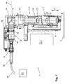
- the laser cutting machine 1 is a flatbed machine, which as such comprises a movement unit 2 in the usual way, which can be moved via a workpiece support 3 indicated in the figures.
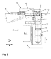
- the main component of the movement unit 2 is a bridge 4, which is likewise shown only schematically in the figures, which spans the workpiece support 3 and moves relative to the stationary workpiece support 3 in the direction of a horizontal x-axis (FIG. FIG. 2 ) can be moved.
- the bridge 4 supports and in turn leads to an assembly 5. This can be moved along the bridge 4 in the direction of a horizontal y-axis (FIG. FIG. 2 ).
- the assembly 5 comprises a carriage 6, which is guided on the bridge 4 in the direction of the y-axis and movable by means of the aforementioned linear drive.
- the carriage 6 in turn supports a machining head in the form of a laser cutting head 7.
- the laser cutting head 7 is movable or deliverable on the carriage 6 in the direction of a vertical z-axis.
- a feed drive for the laser cutting head 7 is a not shown linear drive. Alternatively, for example, a belt drive is conceivable.
- a conventional cutting nozzle 8 At the side facing the workpiece support 3 side of the laser cutting head 7 is provided with a conventional cutting nozzle 8.
- a focus lens designed as a focusing lens 9 of conventional design is housed.
- a deflection housing 10 which receives a deflection optics in the form of a deflection mirror 11.
- a collimation 12 is flanged.
- a device axis 13 of the collimation device 12 extends horizontally and thus perpendicular to the z-axis.
- Essential components of the collimation device 12 are a collimating optics in the form of a collimating lens 14 and an actuator 15, which is designed as a spindle drive and by means of which the collimating lens 14 can be delivered in the direction of the device axis 13. Both the actuator 15 and the collimating lens 14 are housed inside a Kollimationsgephases 16.
- the collimation housing 16 is provided with a connector receptacle 17.
- a cable connector 18 is inserted, which in turn is attached to the collimating device 12 towards the end of a laser light cable 19.
- the laser light cable 19 provides a connection of the assembly 5 with a beam source in the form of an in FIG. 1 indicated solid state laser 20 ago. This generates a laser beam, which is fed in the usual way in the laser light cable 19 and fed through the laser light cable 19 of the assembly 5. In the region of the assembly 5, the laser beam is shown in the figures in the form of a beam axis 21.
- the device axis 13 of the collimation device 12 coincides in the example shown with the axis of the laser beam 21, which passes through the collimating lens 14. Is in place of the collimating lens 14 provided a mirror arrangement, the device axis 13 is defined by the direction (main direction), in which the connection of the entry point and exit point of the laser beam 21 runs on the collimating optics.
- the laser beam 21 is aligned in parallel by means of the collimation device 12.
- the collimating lens 14 of the collimation device 12 is penetrated by the laser beam 21 along the device axis 13.
- the laser beam 21 is deflected by means of the deflection mirror 11 by 90 ° to the focusing lens 9 out.
- the deflection optics or the deflecting mirror 11 can be tiltable or pivotable, so that the laser beam 21 incident on it or on it can in each case be aligned parallel to the z axis.
- the focusing lens 9 generates the laser cutting beam, which ultimately serves as a machining tool, from the laser beam 21, which until then was the raw beam. From the focusing lens 9 of the laser cutting beam is directed to the respective processed, deposited on the workpiece support 3 sheet. All essential functions of the laser cutting machine 1 are numerically controlled.
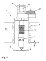
- the laser beam 21 extends in a beam guiding space 22, the space wall of which is formed by a conventional bellows 23.
- the bellows 23 is connected with one longitudinal end to the deflection housing 10 and with the other longitudinal end of the laser cutting head 7. It can be pulled out and compressed in the direction of the z-axis.
- the jet guiding space 22 is filled in the example shown with purified air and hermetically sealed as far as possible against the environment of the assembly 5. About a flow channel not shown in detail the jet guiding space 22 is in fluid communication with a bellows-like gas compensation volume 24, which in detail in FIG FIG. 4 can be seen. In the FIGS. 1 to 3 the gas compensation volume 24 is largely covered by the deflection housing 10. In the interior of the beam guiding space 22 there is a pressure which slightly exceeds the ambient pressure.
- the laser beam 21 in the interior of the beam guiding space 22 is protected against damaging environmental influences, in particular against performance-reducing gases.
- Solid contaminants which reach the interior of the beam guiding space 22 regardless of the protective measures taken, are bound by a dirt absorber (not shown in detail) in the interior of the beam guiding space 22 and thereby kept away from the laser beam 21.
- the laser cutting head 7 is moved in the direction of the z-axis in a position in which the cutting nozzle 8 has a lying on the order of one millimeter distance from the surface of the sheet to be machined. With such a nozzle spacing results in optimal processing results.
- the laser cutting head 7 is raised in the direction of the z-axis, before it moves to the next processing point.
- the laser cutting head 7 is delivered in the direction of the z-axis, in order to maintain the initially set nozzle spacing from the sheet surface approximately at sheet thickness changes.
- the Infeed movements of the laser processing head 7 in the current cutting operation are highly dynamic.
- the required dynamics of the feed movements of the laser cutting head 7 is made possible by the movement-related decoupling of the laser cutting head 7 from the other components of the assembly 5.
- only the laser cutting head 7 moves in the direction of the z-axis during the feed movements.
- the collimation device 12 with the laser light cable 19 connected thereto is stationary in the direction of the z-axis.
- Vibrations of the collimation device 12, which due to the projecting of the collimation 12 perpendicular to the direction of the z-axis take a considerable extent and thus could lead to an impairment of the leadership of the laser beam 21 are avoided.
- the horizontal alignment of the collimation device 12 results in a compact construction of the entire assembly 5.
- the laser light cable 19 can be laid flat and therefore extend with a radius of curvature which is greater than the minimum radius required for laser light cables.
- FIGS. 1 and 2 is the laser cutting head 7 in its raised starting position.
- the Figures 3 and 4 is the laser cutting head 7 against the FIGS. 1 and 2 lowered to the workpiece support 3 out.
- the bellows 23 is compared to the proportions according to the FIGS. 1 and 2 elongated.
- the gas equalization volume 24 has compared with the FIGS. 1 and 2 reduced.
Landscapes
- Physics & Mathematics (AREA)
- Engineering & Computer Science (AREA)
- Optics & Photonics (AREA)
- Plasma & Fusion (AREA)
- Mechanical Engineering (AREA)
- Laser Beam Processing (AREA)
Abstract
Description
Die Erfindung betrifft eine maschinelle Vorrichtung zum Bearbeiten von Werkstücken, beispielsweise von Blechen, mittels eines Laserstrahls,
- mit einem Bearbeitungskopf, der eine Fokussieroptik aufweist, von welcher aus der Laserstrahl als Bearbeitungsstrahl auf ein Werkstück richtbar ist und der in Richtung der Achse des Bearbeitungsstrahls ("z-Achse") zustellbar ist,
- mit einem Laserlichtkabel, über welches der Laserstrahl der Fokussieroptik zuführbar ist sowie
- mit einer Kollimationseinrichtung, die eine zwischen dem zu der Fokussieroptik hin liegenden Ende des Laserlichtkabels und der Fokussieroptik angeordnete und von dem Laserstrahl durchsetzbare Kollimationsoptik umfasst, welche von dem Laserstrahl passierbar ist, wobei die Kollimationseinrichtung eine Ausrichtung ("Einrichtungsachse") aufweist, die parallel zu der Durchsatzrichtung des Laserstrahls an der Kollimationsoptik verläuft.
Eine gattungsgemäße Vorrichtung zum schneidenden Bearbeiten von Blechen wurde in der Vergangenheit von der Firma TRUMPF® Werkzeugmaschinen GmbH + Co. KG, 71254 Ditzingen, Deutschland unter der Bezeichnung "Trumatic® HSL 2502" angeboten. An dieser Vorrichtung wird ein letztlich zum Schneiden von Blechen dienender Laserstrahl mittels eines Festkörperlasers erzeugt und einem Laserschneidkopf über ein Laserlichtkabel zugeführt. In dem Laserschneidkopf ist eine Fokussierlinse untergebracht, von der aus der als Schneidwerkzeug genutzte Laserschneidstrahl auf das jeweils zu bearbeitende Blech gerichtet wird. Zwischen dem zu der Fokussierlinse hin liegenden Ende des Laserlichtkabels einerseits und der Fokussierlinse andererseits ist eine Kollimationslinse vorgesehen, mittels derer der Laserstrahl nach dem Austritt aus dem Laserlichtkabel parallel ausgerichtet wird. Die Kollimationslinse ist im Innern eines Kollimationsgehäuses angeordnet und gemeinsam mit diesem Teil einer Kollimationseinrichtung. Die Kollimationseinrichtung bzw. deren Kollimationsgehäuse ist mit dem Laserschneidkopf starr verbunden. Zur Einstellung eines auf den jeweiligen Anwendungsfall abgestimmten Abstandes zwischen einer Schneiddüse des Laserschneidkopfes und der Oberfläche des zu bearbeitenden Bleches bzw. zur Beibehaltung eines eingestellten Düsenabstandes während des Schneidvorganges werden der Laserschneidkopf und die Kollimationseinrichtung bzw. das Kollimationsgehäuse gemeinschaftlich in Richtung der als z-Achse bezeichneten Achse des Laserschneidstrahls zugestellt. Insbesondere während der Blechbearbeitung sind dabei hochdynamische Bewegungen auszuführen. Die Kollimationseinrichtung besitzt eine Ausrichtung, die mit der Längsachse des Kollimationsgehäuses zusammenfällt. Gegenüber dem Laserschneidkopf ist die Kollimationseinrichtung derart ausgerichtet, dass die Einrichtungsachse bzw. die Längsachse des Kollimationsgehäuses in Richtung der z-Achse also in Richtung der Achse des Laserschneidstrahls verläuft. In dieser Richtung ergibt sich folglich eine verhältnismäßig große Bauhöhe der den Laserschneidkopf und die Kollimationseinrichtung bzw. das Kollimationsgehäuse umfassenden Baugruppe.
- with a machining head, which has focusing optics, from which the laser beam can be directed onto a workpiece as a machining beam and which can be delivered in the direction of the axis of the machining beam ("z-axis"),
- with a laser light cable, via which the laser beam can be fed to the focusing optics, as well as
- with a collimation device, which comprises a collimating optics arranged between the end of the laser light cable facing the focusing optics and the focusing optics and passable by the laser beam, which is passable by the laser beam, wherein the collimation device has an alignment ("device axis") parallel to the throughput direction of the laser beam at the collimating optics runs.
A generic device for cutting process sheets, was offered in the past by the company TRUMPF machine tools ® GmbH + Co. KG, 71254 Ditzingen Germany under the name "Trumatic ® HSL 2502". At this device, a laser beam ultimately serving for cutting sheets is generated by means of a solid-state laser and supplied to a laser cutting head via a laser light cable. In the laser cutting head, a focusing lens is accommodated, from which the laser cutting beam used as a cutting tool is directed onto the respective metal sheet to be processed. Between the lying towards the focusing lens end of the laser light cable on the one hand and the focusing lens on the other hand, a collimating lens is provided, by means of which the laser beam is aligned in parallel after exiting the laser light cable. The collimating lens is arranged inside a collimating housing and together with this part of a collimation device. The collimation device or its collimation housing is rigidly connected to the laser cutting head. To set a matched to the particular application distance between a cutting nozzle of the laser cutting head and the surface of the sheet to be machined or to maintain a set nozzle spacing during the cutting process of the laser cutting head and the Kollimationseinrichtung or Kollimationsgehäuse are jointly referred to in the direction of the z-axis Axis of the laser cutting beam delivered. In particular, during sheet metal processing are doing highly dynamic movements. The collimation device has an orientation that coincides with the longitudinal axis of the collimator housing. Compared to the laser cutting head, the collimation device is oriented such that the device axis or the longitudinal axis of the collimator housing in the direction of the z-axis thus extends in the direction of the axis of the laser cutting beam. In this direction, therefore, results in a relatively large height of the Laser cutting head and the Kollimationseinrichtung or Kollimationsgehäuse comprehensive assembly.
Eine maschinelle Vorrichtung mit einer kompakten Baugruppe mit Kollimationseinrichtung sowie Bearbeitungskopf bereitzustellen, ist Aufgabe der vorliegenden Erfindung.To provide a mechanical device with a compact assembly with collimation and machining head is the object of the present invention.
Erfindungsgemäß gelöst wird diese Aufgabe durch die maschinelle Vorrichtung gemäß Patentanspruch 1.This object is achieved according to the invention by the mechanical device according to
Im Falle der Erfindung ist die Kollimationseinrichtung derart ausgerichtet, dass die Einrichtungsachse in Querrichtung der z-Achse, also in Querrichtung der Achse des von dem Bearbeitungskopf auf zu bearbeitende Werkstücke gerichteten Bearbeitungsstrahls verläuft. Infolgedessen ergibt sich in Richtung der z-Achse eine verhältnismäßig kleine Bauhöhe der den Bearbeitungskopf und die Kollimationseinrichtung umfassenden Baugruppe. Aufgrund der erfindungsgemäßen Ausrichtung kann die Kollimationseinrichtung allerdings quer zu der z-Achse vorkragen. Abhängig von der Brennweite der Kollimationsoptik und deren Verstellweg kann die Kollimationseinrichtung eine beträchtliche Baulänge in Richtung der Einrichtungsachse besitzen. Wäre die Kollimationseinrichtung gleichzeitig mit dem Bearbeitungskopf starr verbunden und wäre sie folglich bei Zustellbewegungen des Bearbeitungskopfes in Richtung der z-Achse mitzubewegen, so bestünde insbesondere bei hochdynamischen Zustellbewegungen die Gefahr, dass die quer zu der z-Achse vorkragende Kollimationseinrichtung in Schwingung gerät und dadurch die Funktionsfähigkeit der Laserstrahlführung und letztlich die Qualität der Laserstrahlbearbeitung beeinträchtigt wird. Um derartige Negativerscheinungen zu vermeiden, ist der Bearbeitungskopf der erfindungsgemäßen Vorrichtung bei Zustellbewegungen in Richtung der z-Achse von der Kollimationseinrichtung entkoppelt. Diese Entkopplung, d.h. die Beweglichkeit des Bearbeitungskopfes relativ zu der Kollimationseinrichtung, ermöglicht eine kompakte Bauweise der den Bearbeitungskopf und die Kollimationseinrichtung umfassenden Baugruppe, ohne dass Einschränkungen der Leistungsfähigkeit der maschinellen Vorrichtung in Kauf genommen werden müssten. Besonders vorteilhaft ist die erfindungsgemäße Entkopplung von Bearbeitungskopf und Kollimationseinrichtung bei Zustellbewegungen des Bearbeitungskopfes in Fällen, in denen die Kollimationseinrichtung eine motorische Stelleinrichtung für die Kollimationsoptik aufweist und folglich eine entsprechend große Masse besitzt, die bei starrer Kopplung von Kollimationseinrichtung und Bearbeitungskopf gemeinschaftlich mit dem Bearbeitungskopf zu bewegen wäre.In the case of the invention, the collimation device is aligned such that the device axis runs in the transverse direction of the z-axis, ie in the transverse direction of the axis of the machining beam directed from the machining head to be processed. As a result, results in the direction of the z-axis, a relatively small height of the machining head and the Kollimationseinrichtung comprehensive assembly. Due to the alignment according to the invention, however, the collimation device can protrude transversely to the z-axis. Depending on the focal length of the collimating optics and their adjustment path, the collimation device can have a considerable length in the direction of the device axis. If the collimation device were rigidly connected to the machining head at the same time and if it were to move along in the direction of the z-axis during feed movements of the machining head, there would be a risk, particularly in the case of highly dynamic feed movements, that the collimation device projecting transversely to the z-axis would oscillate and thereby cause the collimation device to vibrate Functionality of the laser beam guide and ultimately the quality of laser beam processing is impaired. In order to avoid such negative phenomena, the processing head of the device according to the invention is decoupled from the collimation device in the case of feed movements in the direction of the z-axis. These Decoupling, ie the movability of the machining head relative to the collimation device, allows a compact construction of the assembly comprising the machining head and the collimation device, without having to accept limitations in the performance of the machine device. Particularly advantageous is the inventive decoupling of machining head and Kollimationseinrichtung during feed movements of the machining head in cases where the collimation has a motorized actuator for the collimating optics and consequently has a correspondingly large mass to move in rigid coupling of collimation and machining head jointly with the machining head would.
Besondere Ausführungsarten der Erfindung nach Patentanspruch 1 ergeben sich aus den abhängigen Patentansprüchen 2 bis 8.Particular embodiments of the invention according to
Gemäß Patentanspruch 2 ist in bevorzugter Ausgestaltung der Erfindung die Kollimationseinrichtung in Richtung der z-Achse ortsfest. Bewegungen in dieser Richtung werden dementsprechend ausschließlich von dem Bearbeitungskopf ausgeführt.According to claim 2, the collimation device is fixed in the direction of the z-axis in a preferred embodiment of the invention. Accordingly, movements in this direction are performed exclusively by the machining head.
Durch eine besonders kleine Bauhöhe in Richtung der z-Achse bei gleichzeitig einfacher Laserstrahlführung zwischen der Kollimationsoptik und der Fokussieroptik zeichnet sich die Erfindungsbauart gemäß Patentanspruch 3 aus, im Falle derer die Einrichtungsachse der Kollimationseinrichtung unter einem rechten Winkel gegenüber der z-Achse verläuft. Von einem rechten Winkel abweichende Winkel sind aber auch denkbar.Due to a particularly small overall height in the direction of the z-axis with simultaneous simple laser beam guidance between the collimating optics and the focusing optics, the Erfindungsbauart according to
Die Patentansprüche 4 bis 8 betreffen Maßnahmen, die in Weiterbildung der Erfindung getroffen werden, um ungeachtet der Relativbeweglichkeit von Bearbeitungskopf und Kollimationseinrichtung in Richtung der z-Achse eine störungsfreie, leistungsfähige und qualitativ hochwertige Laserbearbeitung zu gewährleisten.The claims 4 to 8 relate to measures that are taken in development of the invention, regardless of the relative mobility of the machining head and collimation in the direction of the z-axis to ensure trouble-free, efficient and high-quality laser processing.
Gemäß Patentanspruch 4 verläuft der Laserstrahl zwischen der Kollimationsoptik und der Fokussieroptik in einem durch eine Raumwand begrenzten Strahlführungsraum. Die Raumwand des Strahlführungsraums ist entsprechend den von dem Bearbeitungskopf ausgeführten Bewegungen in Richtung der z-Achse längenveränderlich. Im Innern des Strahlführungsraums ist der Laserstrahl gegen schädliche Umgebungseinflüsse geschützt.According to claim 4, the laser beam extends between the collimating optics and the focusing optics in a beam guiding space bounded by a room wall. The space wall of the beam guiding space is variable in length in the direction of the z-axis in accordance with the movements made by the machining head. Inside the beam guiding space, the laser beam is protected against damaging environmental influences.
Mit einem in Richtung der z-Achse ausziehbaren und stauchbaren Faltenbalg besitzt der Strahlführungsraum der erfindungsgemäßen Vorrichtung nach Patentanspruch 5 eine Raumwand, die sich in der Praxis vielfach bewährt hat.With a bellows which can be pulled out and compressed in the direction of the z-axis, the beam guiding space of the device according to the invention has, according to
Im Falle der Erfindungsbauart nach Patentanspruch 6 ist der Strahlführungsraum zwischen der Kollimationsoptik und der Fokussieroptik mit einem gasförmigen Medium gefüllt und im wesentlichen hermetisch abgedichtet. Die Zusammensetzung des gasförmigen Mediums ist auf den in dem Strahlführungsraum verlaufenden Laserstrahl abgestimmt und stellt sicher, dass der Laserstrahl in seinen für den Erfolg der Werkstückbearbeitung maßgebenden Eigenschaften nicht beeinträchtigt wird. Die hermetische Abdichtung des Strahlführungsraumes dient dazu, schädliche Umgebungseinflüsse, insbesondere für die Laserstrahlleistung schädliche Gase von dem Laserstrahl fernzuhalten. Das erfindungsgemäße Gasausgleichsvolumen sorgt dafür, dass der Innendruck des Strahlführungsraumes ungeachtet der von dem Bearbeitungskopf ausgeführten Zustellbewegungen weitestgehend konstant bleibt.In the case of Erfindungsbauart according to
Gemäß Patentanspruch 7 ist in weiterer bevorzugter Ausgestaltung der Erfindung vorgesehen, dass in dem Strahlführungsraum zwischen der Kollimationsoptik und der Fokussieroptik ein Überdruck herrscht. Auch dieses Erfindungsmerkmal dient dazu, das Eindringen schädlicher Substanzen in das Innere des Strahlführungsraumes zu verhindern.According to
Verschmutzungen, die unerwünschterweise in den Strahlführungsraum zwischen der Kollimationsoptik und der Fokussieroptik gelangt sind, werden im Falle der Erfindungsbauart nach Patentanspruch 8 durch einen im Inneren des Strahlführungsraumes vorgesehenen Schmutzabsorber gebunden und dadurch von dem Laserstrahl ferngehalten. Als Schmutzabsorber gebräuchlich sind beispielsweise Absorberfolien.Contaminations that have undesirably entered the beam guiding space between the collimating optics and the focusing optics are, in the case of the type of invention according to
Nachstehend wird die Erfindung anhand beispielhafter schematischer Darstellungen näher erläutert. Es zeigen:
Figur 1- eine Schnittdarstellung einer in einem ersten Betriebszustand befindlichen Baugruppe einer Laserschneidmaschine für die Blechbearbeitung,
- Figur 2
- einen schematisierten Teilschnitt der Baugruppe gemäß
Figur 1 , Figur 3- die Baugruppe
gemäß den Figuren 1 und2 in einem zweiten Betriebszustand und - Figur 4
- die
Baugruppe gemäß Figur 3 in der Ansicht in Richtung des Pfeils IV inFigur 3
- FIG. 1
- a sectional view of a present in a first operating state assembly of a laser cutting machine for sheet metal working,
- FIG. 2
- a schematic partial section of the assembly according to
FIG. 1 . - FIG. 3
- the assembly according to
FIGS. 1 and2 in a second operating state and - FIG. 4
- the module according to
FIG. 3 in the view in the direction of the arrow IV inFIG. 3 ,
Eine in den Abbildungen teilweise dargestellte maschinelle Vorrichtung zum Bearbeiten von Blechen ist als Laserschneidmaschine 1 ausgeführt. Bei der Laserschneidmaschine 1 handelt es sich um eine Flachbettmaschine, die als solche in üblicher Weise eine Bewegungseinheit 2 umfasst, die über eine in den Figuren angedeutete Werkstückauflage 3 verfahrbar ist. Hauptbestandteil der Bewegungseinheit 2 ist eine in den Figuren ebenfalls nur andeutungsweise gezeigte Brücke 4, welche die Werkstückauflage 3 überspannt und relativ zu der stationären Werkstückauflage 3 in Richtung einer horizontalen x-Achse (
Die Baugruppe 5 umfasst einen Schlitten 6, der an der Brücke 4 in Richtung der y-Achse geführt und mittels des vorstehend genannten Linearantriebes verfahrbar ist. Der Schlitten 6 seinerseits lagert einen Bearbeitungskopf in Form eines Laserschneidkopfes 7. Der Laserschneidkopf 7 ist an dem Schlitten 6 in Richtung einer vertikalen z-Achse beweglich bzw. zustellbar. Als Zustellantrieb für den Laserschneidkopf 7 dient ein nicht gezeigter Linearantrieb. Alternativ ist beispielsweise auch ein Zahnriemenantrieb denkbar. An der zu der Werkstückauflage 3 hin weisenden Seite ist der Laserschneidkopf 7 mit einer herkömmlichen Schneiddüse 8 versehen. Im Innern des Laserschneidkopfes 7 ist eine als Fokussierlinse 9 üblicher Bauart ausgeführte Fokussieroptik untergebracht.The
Starr mit dem Schlitten 6 verbunden und folglich in Richtung der z-Achse ortsfest ist ein Umlenkgehäuse 10, das eine Umlenkoptik in Form eines Umlenkspiegels 11 aufnimmt.Rigid connected to the
An das Umlenkgehäuse 10 ist eine Kollimationseinrichtung 12 angeflanscht. Eine Einrichtungsachse 13 der Kollimationseinrichtung 12 verläuft horizontal und folglich senkrecht zu der z-Achse. Wesentliche Komponenten der Kollimationseinrichtung 12 sind eine Kollimationsoptik in Form einer Kollimationslinse 14 sowie ein Stellantrieb 15, der als Spindelantrieb ausgebildet ist und mittels dessen die Kollimationslinse 14 in Richtung der Einrichtungsachse 13 zugestellt werden kann. Sowohl der Stellantrieb 15 als auch die Kollimationslinse 14 sind im Innern eines Kollimationsgehäuses 16 untergebracht.At the
An der von dem Umlenkgehäuse 10 abliegenden Seite ist das Kollimationsgehäuse 16 mit einer Steckeraufnahme 17 versehen. In die Steckeraufnahme 17 ist ein Kabelstecker 18 eingesteckt, der seinerseits an dem zu der Kollimationseinrichtung 12 hin weisenden Ende eines Laserlichtkabels 19 angebracht ist.At the side remote from the
Das Laserlichtkabel 19 stellt eine Verbindung der Baugruppe 5 mit einer Strahlquelle in Form eines in
Die Einrichtungsachse 13 der Kollimationseinrichtung 12 fällt in dem gezeigten Beispielsfall mit der Achse des Laserstrahls 21 zusammen, welcher die Kollimationslinse 14 durchsetzt. Ist an Stelle der Kollimationslinse 14 eine Spiegelanordnung vorgesehen, so wird die Einrichtungsachse 13 durch die Richtung (Hauptrichtung) definiert, in welcher die Verbindung von Eintrittsstelle und Austrittsstelle des Laserstrahls 21 an der Kollimationsoptik verläuft.The
Nach dem Austritt aus dem Laserlichtkabel 19 wird der Laserstrahl 21 mittels der Kollimationseinrichtung 12 parallel ausgerichtet. Die Kollimationslinse 14 der Kollimationseinrichtung 12 wird von dem Laserstrahl 21 entlang der Einrichtungsachse 13 durchsetzt. Nach dem Passieren der Kollimationslinse 14 wird der Laserstrahl 21 mittels des Umlenkspiegels 11 um 90° zu der Fokussierlinse 9 hin umgelenkt. Die Umlenkoptik bzw. der Umlenkspiegel 11 kann kipp- bzw. schwenkbar sein, so dass der an ihr bzw. ihm einfallende Laserstrahl 21 in jedem Fall parallel zu der z-Achse ausgerichtet werden kann. Die Fokussierlinse 9 erzeugt aus dem bis dahin als Rohstrahl vorliegenden Laserstrahl 21 den letztlich als Bearbeitungswerkzeug dienenden Laserschneidstrahl. Von der Fokussierlinse 9 aus wird der Laserschneidstrahl auf das jeweils zu bearbeitende, auf der Werkstückauflage 3 abgelegte Blech gerichtet. Alle wesentlichen Funktionen der Laserschneidmaschine 1 sind numerisch gesteuert.After exiting the
Zwischen dem Umlenkgehäuse 10 und dem Laserschneidkopf 7 verläuft der Laserstrahl 21 in einem Strahlführungsraum 22, dessen Raumwand von einem herkömmlichen Faltenbalg 23 gebildet ist. Der Faltenbalg 23 ist mit einem Längsende an das Umlenkgehäuse 10 und mit dem anderen Längsende an den Laserschneidkopf 7 angebunden. Er kann in Richtung der z-Achse ausgezogen und gestaucht werden.Between the
Der Strahlführungsraum 22 ist in dem gezeigten Beispielsfall mit gereinigter Luft gefüllt und weitestmöglich hermetisch gegen die Umgebung der Baugruppe 5 abgedichtet. Über einen nicht im Einzelnen gezeigten Strömungskanal steht der Strahlführungsraum 22 mit einem balgartigen Gasausgleichsvolumen 24 in Strömungsverbindung, das im Einzelnen in
Durch die Gasfüllung des Strahlführungsraumes 22 sowie durch den im Innern des Strahlführungsraumes 22 herrschenden Überdruck wird der Laserstrahl 21 im Innern des Strahlführungsraumes 22 gegen schädliche Umgebungseinflüsse, insbesondere vor leistungsmindernden Gasen geschützt. Feste Verschmutzungen, die ungeachtet der getroffenen Schutzmaßnahmen in das Innere des Strahlführungsraumes 22 gelangen, werden durch einen nicht im Einzelnen gezeigten Schmutzabsorber im Innern des Strahlführungsraumes 22 gebunden und dadurch von dem Laserstrahl 21 ferngehalten.By the gas filling of the
Im Schneidbetrieb ist der Laserschneidkopf 7 in Richtung der z-Achse in eine Position bewegt, in welcher die Schneiddüse 8 einen in der Größenordnung von einem Millimeter liegenden Abstand von der Oberfläche des zu bearbeitenden Bleches aufweist. Bei einem derartigen Düsenabstand ergeben sich optimale Bearbeitungsergebnisse. Eine Zustellbewegung in Richtung der z-Achse führt der Laserschneidkopf 7 z.B. vor Beginn des Schneidbetriebes aus, um den gewünschten Sollabstand von der Oberfläche des zu bearbeitenden Bleches einzustellen. Nach Beendigung einer Bearbeitung wird der Laserschneidkopf 7 in Richtung der z-Achse angehoben, ehe er zu der nächsten Bearbeitungsstelle verfährt. Im laufenden Schneidbetrieb wird der Laserschneidkopf 7 in Richtung der z-Achse zugestellt, um den anfänglich eingestellten Düsenabstand von der Blechoberfläche etwa bei Blechdickenänderungen beizubehalten. Insbesondere die Zustellbewegungen des Laserbearbeitungskopfes 7 im laufenden Schneidbetrieb sind hochdynamisch. Die erforderliche Dynamik der Zustellbewegungen des Laserschneidkopfes 7 wird durch die bewegungsmäßige Entkopplung des Laserschneidkopfes 7 von den übrigen Komponenten der Baugruppe 5 ermöglicht. So bewegt sich bei den Zustellbewegungen ausschließlich der Laserschneidkopf 7 in Richtung der z-Achse.In the cutting operation, the
Insbesondere die Kollimationseinrichtung 12 mit dem daran angeschlossenen Laserlichtkabel 19 ist in Richtung der z-Achse ortsfest. Infolgedessen ist bei den Zustellbewegungen des Laserschneidkopfes 7 lediglich eine geringe Masse in Richtung der z-Achse zu bewegen. Schwingungen der Kollimationseinrichtung 12, die aufgrund des Vorkragens der Kollimationseinrichtung 12 senkrecht zu der Richtung der z-Achse einen beachtlichen Umfang annähmen und folglich zu einer Beeinträchtigung der Führung des Laserstrahls 21 führen könnten, werden vermieden. Gleichzeitig bewirkt die horizontale Ausrichtung der Kollimationseinrichtung 12 eine kompakte Bauweise der gesamten Baugruppe 5. Das Laserlichtkabel 19 kann flach verlegt werden und daher mit einem Krümmungsradius verlaufen, der größer ist als der für Laserlichtkabel zu fordernde Mindestradius.In particular, the
Abweichend von den dargestellten Verhältnissen wäre auch eine Ausrichtung der Kollimationseinrichtung 12 unter einem spitzen Winkel α gegen die z-Achse denkbar. Mit einer derartigen Ausrichtung ist die Kollimationseinrichtung 12 in
Gemäß den
Claims (8)
Priority Applications (2)
| Application Number | Priority Date | Filing Date | Title |
|---|---|---|---|
| EP08010660A EP2133171B1 (en) | 2008-06-12 | 2008-06-12 | Machine device for processing workpieces using a laser beam |
| US12/483,435 US8314361B2 (en) | 2008-06-12 | 2009-06-12 | Device for laser machining |
Applications Claiming Priority (1)
| Application Number | Priority Date | Filing Date | Title |
|---|---|---|---|
| EP08010660A EP2133171B1 (en) | 2008-06-12 | 2008-06-12 | Machine device for processing workpieces using a laser beam |
Publications (2)
| Publication Number | Publication Date |
|---|---|
| EP2133171A1 true EP2133171A1 (en) | 2009-12-16 |
| EP2133171B1 EP2133171B1 (en) | 2012-08-08 |
Family
ID=40010826
Family Applications (1)
| Application Number | Title | Priority Date | Filing Date |
|---|---|---|---|
| EP08010660A Not-in-force EP2133171B1 (en) | 2008-06-12 | 2008-06-12 | Machine device for processing workpieces using a laser beam |
Country Status (2)
| Country | Link |
|---|---|
| US (1) | US8314361B2 (en) |
| EP (1) | EP2133171B1 (en) |
Cited By (4)
| Publication number | Priority date | Publication date | Assignee | Title |
|---|---|---|---|---|
| CN102756224A (en) * | 2011-04-29 | 2012-10-31 | 宁波市拓新焊接技术有限公司 | Special welder for welding corrugated pipes |
| CN106392338A (en) * | 2016-10-09 | 2017-02-15 | 湖北工业大学 | Waste solar cell cutting device |
| CN110673354A (en) * | 2019-10-16 | 2020-01-10 | 中国航空工业集团公司洛阳电光设备研究所 | Method and system for adjusting position degree of spherical optical window relative to two azimuth pitching scanning axes |
| DE102021123617A1 (en) | 2021-09-13 | 2023-03-16 | Precitec Gmbh & Co. Kg | Laser processing head with glue trap |
Families Citing this family (18)
| Publication number | Priority date | Publication date | Assignee | Title |
|---|---|---|---|---|
| DE102010020732B4 (en) * | 2010-05-17 | 2013-10-10 | Rena Gmbh | Device and method for aligning a laser head and multi-laser block for a production plant |
| EP2409808A1 (en) * | 2010-07-22 | 2012-01-25 | Bystronic Laser AG | Laser processing machine |
| EP2667998B1 (en) | 2011-01-27 | 2020-11-18 | Bystronic Laser AG | Laser processing machine and method for centering a focused laser beam |
| US9289852B2 (en) | 2011-01-27 | 2016-03-22 | Bystronic Laser Ag | Laser processing machine, laser cutting machine, and method for adjusting a focused laser beam |
| CN102615424A (en) * | 2011-12-31 | 2012-08-01 | 武汉金运激光股份有限公司 | Laser cutting head with focusing device and focal length determining method |
| EP2883647B1 (en) | 2013-12-12 | 2019-05-29 | Bystronic Laser AG | Method for configuring a laser machining device |
| US20230271275A9 (en) * | 2014-02-26 | 2023-08-31 | Gerber Technology Llc | Cutting machinery laser system |
| US10509390B2 (en) | 2015-02-12 | 2019-12-17 | Glowforge Inc. | Safety and reliability guarantees for laser fabrication |
| CN107438494B (en) * | 2015-02-12 | 2023-09-19 | 格罗弗治公司 | Visual preview for laser machining |
| WO2018098396A1 (en) | 2016-11-25 | 2018-05-31 | Glowforge Inc. | Multi-user computer-numerically-controlled machine |
| WO2018098398A1 (en) | 2016-11-25 | 2018-05-31 | Glowforge Inc. | Preset optical components in a computer numerically controlled machine |
| WO2018098397A1 (en) | 2016-11-25 | 2018-05-31 | Glowforge Inc. | Calibration of computer-numerically-controlled machine |
| WO2018098393A1 (en) | 2016-11-25 | 2018-05-31 | Glowforge Inc. | Housing for computer-numerically-controlled machine |
| WO2018098399A1 (en) | 2016-11-25 | 2018-05-31 | Glowforge Inc. | Controlled deceleration of moveable components in a computer numerically controlled machine |
| WO2018098394A1 (en) | 2016-11-25 | 2018-05-31 | Glowforge Inc. | Fabrication with image tracing |
| WO2019070536A1 (en) * | 2017-10-05 | 2019-04-11 | Mct Of Wisconsin, Inc. | Cutting machinery laser system |
| US11740608B2 (en) | 2020-12-24 | 2023-08-29 | Glowforge, Inc | Computer numerically controlled fabrication using projected information |
| US11698622B2 (en) | 2021-03-09 | 2023-07-11 | Glowforge Inc. | Previews for computer numerically controlled fabrication |
Citations (6)
| Publication number | Priority date | Publication date | Assignee | Title |
|---|---|---|---|---|
| US4997250A (en) * | 1989-11-17 | 1991-03-05 | General Electric Company | Fiber output coupler with beam shaping optics for laser materials processing system |
| DE9407288U1 (en) * | 1994-05-02 | 1994-08-04 | Trumpf Gmbh & Co | Laser cutting machine with focus position adjustment |
| US6501043B1 (en) | 1999-10-22 | 2002-12-31 | Medtronic, Inc. | Apparatus and method for laser welding of ribbons |
| US20030196993A1 (en) * | 2002-04-18 | 2003-10-23 | Applied Materials, Inc. | Thermal flux deposition by scanning |
| US20050150876A1 (en) * | 2003-12-18 | 2005-07-14 | Roberto Menin | Method and device for laser welding |
| EP1716963A1 (en) * | 2005-04-26 | 2006-11-02 | Highyag Lasertechnologie GmbH | Optical arrangement for remote laser machining which creates a 3D working area |
Family Cites Families (11)
| Publication number | Priority date | Publication date | Assignee | Title |
|---|---|---|---|---|
| US5109148A (en) * | 1990-01-26 | 1992-04-28 | Mitsubishi Denki Kabushiki Kaisha | Positioning device for a machining apparatus |
| JP2591371B2 (en) * | 1991-07-03 | 1997-03-19 | 三菱電機株式会社 | Laser processing equipment |
| JP2798530B2 (en) * | 1991-07-26 | 1998-09-17 | 三菱電機株式会社 | Laser processing machine |
| JPH06335883A (en) * | 1993-05-27 | 1994-12-06 | Toyoda Mach Works Ltd | Robot controller |
| JP3633117B2 (en) * | 1996-07-17 | 2005-03-30 | 三菱電機株式会社 | Optical scanning laser processing machine |
| DE29714489U1 (en) * | 1997-08-13 | 1997-10-09 | Trumpf Gmbh & Co | Laser processing machine with gas compensation volume |
| JPH11221692A (en) * | 1998-02-04 | 1999-08-17 | Amada Eng Center Co Ltd | Laser beam guide method, and three-dimensional laser beam machine using the method |
| JP4583652B2 (en) * | 2001-04-18 | 2010-11-17 | 株式会社アマダ | Laser processing machine |
| JP4358458B2 (en) * | 2001-06-01 | 2009-11-04 | コマツNtc株式会社 | Laser processing equipment |
| JP2003071584A (en) * | 2001-08-30 | 2003-03-11 | Amada Co Ltd | Optical path protective bellows for laser beam machine |
| US20060157457A1 (en) * | 2004-12-08 | 2006-07-20 | Matsushita Electric Industrial Co., Ltd. | Hybrid laser processing method and hybrid laser torch used in the method |
-
2008
- 2008-06-12 EP EP08010660A patent/EP2133171B1/en not_active Not-in-force
-
2009
- 2009-06-12 US US12/483,435 patent/US8314361B2/en not_active Expired - Fee Related
Patent Citations (6)
| Publication number | Priority date | Publication date | Assignee | Title |
|---|---|---|---|---|
| US4997250A (en) * | 1989-11-17 | 1991-03-05 | General Electric Company | Fiber output coupler with beam shaping optics for laser materials processing system |
| DE9407288U1 (en) * | 1994-05-02 | 1994-08-04 | Trumpf Gmbh & Co | Laser cutting machine with focus position adjustment |
| US6501043B1 (en) | 1999-10-22 | 2002-12-31 | Medtronic, Inc. | Apparatus and method for laser welding of ribbons |
| US20030196993A1 (en) * | 2002-04-18 | 2003-10-23 | Applied Materials, Inc. | Thermal flux deposition by scanning |
| US20050150876A1 (en) * | 2003-12-18 | 2005-07-14 | Roberto Menin | Method and device for laser welding |
| EP1716963A1 (en) * | 2005-04-26 | 2006-11-02 | Highyag Lasertechnologie GmbH | Optical arrangement for remote laser machining which creates a 3D working area |
Cited By (4)
| Publication number | Priority date | Publication date | Assignee | Title |
|---|---|---|---|---|
| CN102756224A (en) * | 2011-04-29 | 2012-10-31 | 宁波市拓新焊接技术有限公司 | Special welder for welding corrugated pipes |
| CN106392338A (en) * | 2016-10-09 | 2017-02-15 | 湖北工业大学 | Waste solar cell cutting device |
| CN110673354A (en) * | 2019-10-16 | 2020-01-10 | 中国航空工业集团公司洛阳电光设备研究所 | Method and system for adjusting position degree of spherical optical window relative to two azimuth pitching scanning axes |
| DE102021123617A1 (en) | 2021-09-13 | 2023-03-16 | Precitec Gmbh & Co. Kg | Laser processing head with glue trap |
Also Published As
| Publication number | Publication date |
|---|---|
| US8314361B2 (en) | 2012-11-20 |
| US20090308851A1 (en) | 2009-12-17 |
| EP2133171B1 (en) | 2012-08-08 |
Similar Documents
| Publication | Publication Date | Title |
|---|---|---|
| EP2133171B1 (en) | Machine device for processing workpieces using a laser beam | |
| EP1609556B1 (en) | Modular hybrid laser welding head | |
| DE19948895B4 (en) | Laser welding device | |
| DE102006030130B3 (en) | Workpiece machining method for, e.g., industrial robot, involves compensating deviation of determined actual-position from reference-movement path and deviation of determined actual-speed vector from measured reference-speed vector | |
| DE102010018686B4 (en) | Apparatus and method for laser cladding with powdered filler material | |
| DE4317384C2 (en) | Laser machining head | |
| DE102009017900B4 (en) | Laser processing head for brazing or welding with a wire feeder with integrated light-section module | |
| DE102014102955A1 (en) | Laser beam machine for the thermal processing of workpieces | |
| DE102018217940A1 (en) | Method and processing machine for processing a workpiece | |
| DE202017101590U1 (en) | Device for guiding a laser beam onto a workpiece | |
| WO2012052525A1 (en) | Device for the highly dynamic movement of the working point of a beam | |
| EP2699379A2 (en) | Laser beam welding device and laser beam welding method | |
| AT523568B1 (en) | bending machine | |
| WO2011026486A1 (en) | Laser processing machine with redundant axes | |
| DE10226359A1 (en) | Laser processing head, especially for cutting workpiece using laser beam, has device near outlet opening between housing and laser nozzle for producing gas flow transverse to laser beam | |
| DE102015006421B4 (en) | Process for joining components | |
| EP3098022B1 (en) | Replaceable optical module for a laser-based machining device and corresponding laser-based machining device | |
| WO2020120047A1 (en) | Pipe processing machine for cutting pipes or profiled sections using a laser beam | |
| DE102006017629A1 (en) | Industrial laser cutting or welding process and assembly has sensor for correction of dynamically induced errors | |
| DE102018206729A1 (en) | Laser processing head and laser processing machine with it | |
| DE102010049453A1 (en) | Highly dynamic translationally movable device for combining an energetic beam effect and an auxiliary medium at an action point | |
| DE10151828B4 (en) | Apparatus and method for laser beam soldering, in particular laser beam brazing | |
| EP0722806A1 (en) | Apparatus for laser welding workpieces | |
| EP3486019A1 (en) | Laser soldering lens for joining coated workpieces | |
| WO2003051570A1 (en) | Method for producing a weld seam by means of a laser beam |
Legal Events
| Date | Code | Title | Description |
|---|---|---|---|
| PUAI | Public reference made under article 153(3) epc to a published international application that has entered the european phase |
Free format text: ORIGINAL CODE: 0009012 |
|
| AK | Designated contracting states |
Kind code of ref document: A1 Designated state(s): AT BE BG CH CY CZ DE DK EE ES FI FR GB GR HR HU IE IS IT LI LT LU LV MC MT NL NO PL PT RO SE SI SK TR |
|
| AX | Request for extension of the european patent |
Extension state: AL BA MK RS |
|
| 17P | Request for examination filed |
Effective date: 20100604 |
|
| 17Q | First examination report despatched |
Effective date: 20100701 |
|
| AKX | Designation fees paid |
Designated state(s): AT BE BG CH CY CZ DE DK EE ES FI FR GB GR HR HU IE IS IT LI LT LU LV MC MT NL NO PL PT RO SE SI SK TR |
|
| GRAP | Despatch of communication of intention to grant a patent |
Free format text: ORIGINAL CODE: EPIDOSNIGR1 |
|
| RIC1 | Information provided on ipc code assigned before grant |
Ipc: B23K 26/38 20060101AFI20120118BHEP |
|
| GRAS | Grant fee paid |
Free format text: ORIGINAL CODE: EPIDOSNIGR3 |
|
| GRAA | (expected) grant |
Free format text: ORIGINAL CODE: 0009210 |
|
| AK | Designated contracting states |
Kind code of ref document: B1 Designated state(s): AT BE BG CH CY CZ DE DK EE ES FI FR GB GR HR HU IE IS IT LI LT LU LV MC MT NL NO PL PT RO SE SI SK TR |
|
| REG | Reference to a national code |
Ref country code: GB Ref legal event code: FG4D Free format text: NOT ENGLISH |
|
| REG | Reference to a national code |
Ref country code: AT Ref legal event code: REF Ref document number: 569482 Country of ref document: AT Kind code of ref document: T Effective date: 20120815 Ref country code: CH Ref legal event code: EP |
|
| REG | Reference to a national code |
Ref country code: IE Ref legal event code: FG4D Free format text: LANGUAGE OF EP DOCUMENT: GERMAN |
|
| REG | Reference to a national code |
Ref country code: DE Ref legal event code: R096 Ref document number: 502008007862 Country of ref document: DE Effective date: 20121004 |
|
| REG | Reference to a national code |
Ref country code: NL Ref legal event code: VDEP Effective date: 20120808 |
|
| REG | Reference to a national code |
Ref country code: LT Ref legal event code: MG4D Effective date: 20120808 |
|
| PG25 | Lapsed in a contracting state [announced via postgrant information from national office to epo] |
Ref country code: CY Free format text: LAPSE BECAUSE OF FAILURE TO SUBMIT A TRANSLATION OF THE DESCRIPTION OR TO PAY THE FEE WITHIN THE PRESCRIBED TIME-LIMIT Effective date: 20120808 Ref country code: NO Free format text: LAPSE BECAUSE OF FAILURE TO SUBMIT A TRANSLATION OF THE DESCRIPTION OR TO PAY THE FEE WITHIN THE PRESCRIBED TIME-LIMIT Effective date: 20121108 Ref country code: FI Free format text: LAPSE BECAUSE OF FAILURE TO SUBMIT A TRANSLATION OF THE DESCRIPTION OR TO PAY THE FEE WITHIN THE PRESCRIBED TIME-LIMIT Effective date: 20120808 Ref country code: HR Free format text: LAPSE BECAUSE OF FAILURE TO SUBMIT A TRANSLATION OF THE DESCRIPTION OR TO PAY THE FEE WITHIN THE PRESCRIBED TIME-LIMIT Effective date: 20120808 Ref country code: IS Free format text: LAPSE BECAUSE OF FAILURE TO SUBMIT A TRANSLATION OF THE DESCRIPTION OR TO PAY THE FEE WITHIN THE PRESCRIBED TIME-LIMIT Effective date: 20121208 Ref country code: LT Free format text: LAPSE BECAUSE OF FAILURE TO SUBMIT A TRANSLATION OF THE DESCRIPTION OR TO PAY THE FEE WITHIN THE PRESCRIBED TIME-LIMIT Effective date: 20120808 |
|
| PG25 | Lapsed in a contracting state [announced via postgrant information from national office to epo] |
Ref country code: SI Free format text: LAPSE BECAUSE OF FAILURE TO SUBMIT A TRANSLATION OF THE DESCRIPTION OR TO PAY THE FEE WITHIN THE PRESCRIBED TIME-LIMIT Effective date: 20120808 Ref country code: PT Free format text: LAPSE BECAUSE OF FAILURE TO SUBMIT A TRANSLATION OF THE DESCRIPTION OR TO PAY THE FEE WITHIN THE PRESCRIBED TIME-LIMIT Effective date: 20121210 Ref country code: PL Free format text: LAPSE BECAUSE OF FAILURE TO SUBMIT A TRANSLATION OF THE DESCRIPTION OR TO PAY THE FEE WITHIN THE PRESCRIBED TIME-LIMIT Effective date: 20120808 Ref country code: LV Free format text: LAPSE BECAUSE OF FAILURE TO SUBMIT A TRANSLATION OF THE DESCRIPTION OR TO PAY THE FEE WITHIN THE PRESCRIBED TIME-LIMIT Effective date: 20120808 Ref country code: GR Free format text: LAPSE BECAUSE OF FAILURE TO SUBMIT A TRANSLATION OF THE DESCRIPTION OR TO PAY THE FEE WITHIN THE PRESCRIBED TIME-LIMIT Effective date: 20121109 Ref country code: SE Free format text: LAPSE BECAUSE OF FAILURE TO SUBMIT A TRANSLATION OF THE DESCRIPTION OR TO PAY THE FEE WITHIN THE PRESCRIBED TIME-LIMIT Effective date: 20120808 |
|
| PG25 | Lapsed in a contracting state [announced via postgrant information from national office to epo] |
Ref country code: NL Free format text: LAPSE BECAUSE OF FAILURE TO SUBMIT A TRANSLATION OF THE DESCRIPTION OR TO PAY THE FEE WITHIN THE PRESCRIBED TIME-LIMIT Effective date: 20120808 |
|
| PG25 | Lapsed in a contracting state [announced via postgrant information from national office to epo] |
Ref country code: DK Free format text: LAPSE BECAUSE OF FAILURE TO SUBMIT A TRANSLATION OF THE DESCRIPTION OR TO PAY THE FEE WITHIN THE PRESCRIBED TIME-LIMIT Effective date: 20120808 Ref country code: CZ Free format text: LAPSE BECAUSE OF FAILURE TO SUBMIT A TRANSLATION OF THE DESCRIPTION OR TO PAY THE FEE WITHIN THE PRESCRIBED TIME-LIMIT Effective date: 20120808 Ref country code: ES Free format text: LAPSE BECAUSE OF FAILURE TO SUBMIT A TRANSLATION OF THE DESCRIPTION OR TO PAY THE FEE WITHIN THE PRESCRIBED TIME-LIMIT Effective date: 20121119 Ref country code: RO Free format text: LAPSE BECAUSE OF FAILURE TO SUBMIT A TRANSLATION OF THE DESCRIPTION OR TO PAY THE FEE WITHIN THE PRESCRIBED TIME-LIMIT Effective date: 20120808 Ref country code: EE Free format text: LAPSE BECAUSE OF FAILURE TO SUBMIT A TRANSLATION OF THE DESCRIPTION OR TO PAY THE FEE WITHIN THE PRESCRIBED TIME-LIMIT Effective date: 20120808 |
|
| PG25 | Lapsed in a contracting state [announced via postgrant information from national office to epo] |
Ref country code: SK Free format text: LAPSE BECAUSE OF FAILURE TO SUBMIT A TRANSLATION OF THE DESCRIPTION OR TO PAY THE FEE WITHIN THE PRESCRIBED TIME-LIMIT Effective date: 20120808 |
|
| PLBE | No opposition filed within time limit |
Free format text: ORIGINAL CODE: 0009261 |
|
| STAA | Information on the status of an ep patent application or granted ep patent |
Free format text: STATUS: NO OPPOSITION FILED WITHIN TIME LIMIT |
|
| 26N | No opposition filed |
Effective date: 20130510 |
|
| PG25 | Lapsed in a contracting state [announced via postgrant information from national office to epo] |
Ref country code: BG Free format text: LAPSE BECAUSE OF FAILURE TO SUBMIT A TRANSLATION OF THE DESCRIPTION OR TO PAY THE FEE WITHIN THE PRESCRIBED TIME-LIMIT Effective date: 20121108 |
|
| REG | Reference to a national code |
Ref country code: DE Ref legal event code: R097 Ref document number: 502008007862 Country of ref document: DE Effective date: 20130510 |
|
| BERE | Be: lapsed |
Owner name: TRUMPF SACHSEN G.M.B.H. Effective date: 20130630 |
|
| PG25 | Lapsed in a contracting state [announced via postgrant information from national office to epo] |
Ref country code: MC Free format text: LAPSE BECAUSE OF FAILURE TO SUBMIT A TRANSLATION OF THE DESCRIPTION OR TO PAY THE FEE WITHIN THE PRESCRIBED TIME-LIMIT Effective date: 20120808 |
|
| REG | Reference to a national code |
Ref country code: IE Ref legal event code: MM4A |
|
| PG25 | Lapsed in a contracting state [announced via postgrant information from national office to epo] |
Ref country code: BE Free format text: LAPSE BECAUSE OF NON-PAYMENT OF DUE FEES Effective date: 20130630 |
|
| PG25 | Lapsed in a contracting state [announced via postgrant information from national office to epo] |
Ref country code: IE Free format text: LAPSE BECAUSE OF NON-PAYMENT OF DUE FEES Effective date: 20130612 |
|
| REG | Reference to a national code |
Ref country code: AT Ref legal event code: MM01 Ref document number: 569482 Country of ref document: AT Kind code of ref document: T Effective date: 20130612 |
|
| PG25 | Lapsed in a contracting state [announced via postgrant information from national office to epo] |
Ref country code: AT Free format text: LAPSE BECAUSE OF NON-PAYMENT OF DUE FEES Effective date: 20130612 |
|
| PG25 | Lapsed in a contracting state [announced via postgrant information from national office to epo] |
Ref country code: MT Free format text: LAPSE BECAUSE OF FAILURE TO SUBMIT A TRANSLATION OF THE DESCRIPTION OR TO PAY THE FEE WITHIN THE PRESCRIBED TIME-LIMIT Effective date: 20120808 |
|
| REG | Reference to a national code |
Ref country code: FR Ref legal event code: PLFP Year of fee payment: 8 |
|
| PG25 | Lapsed in a contracting state [announced via postgrant information from national office to epo] |
Ref country code: TR Free format text: LAPSE BECAUSE OF FAILURE TO SUBMIT A TRANSLATION OF THE DESCRIPTION OR TO PAY THE FEE WITHIN THE PRESCRIBED TIME-LIMIT Effective date: 20120808 |
|
| PG25 | Lapsed in a contracting state [announced via postgrant information from national office to epo] |
Ref country code: HU Free format text: LAPSE BECAUSE OF FAILURE TO SUBMIT A TRANSLATION OF THE DESCRIPTION OR TO PAY THE FEE WITHIN THE PRESCRIBED TIME-LIMIT; INVALID AB INITIO Effective date: 20080612 Ref country code: LU Free format text: LAPSE BECAUSE OF NON-PAYMENT OF DUE FEES Effective date: 20130612 |
|
| PGFP | Annual fee paid to national office [announced via postgrant information from national office to epo] |
Ref country code: GB Payment date: 20150623 Year of fee payment: 8 Ref country code: CH Payment date: 20150623 Year of fee payment: 8 Ref country code: DE Payment date: 20150625 Year of fee payment: 8 |
|
| PGFP | Annual fee paid to national office [announced via postgrant information from national office to epo] |
Ref country code: FR Payment date: 20150623 Year of fee payment: 8 |
|
| PGFP | Annual fee paid to national office [announced via postgrant information from national office to epo] |
Ref country code: IT Payment date: 20150625 Year of fee payment: 8 |
|
| REG | Reference to a national code |
Ref country code: DE Ref legal event code: R119 Ref document number: 502008007862 Country of ref document: DE |
|
| REG | Reference to a national code |
Ref country code: CH Ref legal event code: PL |
|
| GBPC | Gb: european patent ceased through non-payment of renewal fee |
Effective date: 20160612 |
|
| REG | Reference to a national code |
Ref country code: FR Ref legal event code: ST Effective date: 20170228 |
|
| PG25 | Lapsed in a contracting state [announced via postgrant information from national office to epo] |
Ref country code: FR Free format text: LAPSE BECAUSE OF NON-PAYMENT OF DUE FEES Effective date: 20160630 Ref country code: DE Free format text: LAPSE BECAUSE OF NON-PAYMENT OF DUE FEES Effective date: 20170103 Ref country code: CH Free format text: LAPSE BECAUSE OF NON-PAYMENT OF DUE FEES Effective date: 20160630 Ref country code: LI Free format text: LAPSE BECAUSE OF NON-PAYMENT OF DUE FEES Effective date: 20160630 |
|
| PG25 | Lapsed in a contracting state [announced via postgrant information from national office to epo] |
Ref country code: GB Free format text: LAPSE BECAUSE OF NON-PAYMENT OF DUE FEES Effective date: 20160612 |
|
| PG25 | Lapsed in a contracting state [announced via postgrant information from national office to epo] |
Ref country code: IT Free format text: LAPSE BECAUSE OF NON-PAYMENT OF DUE FEES Effective date: 20160612 |