EP2131998B1 - Adaptive design of fixture for thin-walled shell/cylindrical components - Google Patents
Adaptive design of fixture for thin-walled shell/cylindrical components Download PDFInfo
- Publication number
- EP2131998B1 EP2131998B1 EP08718606A EP08718606A EP2131998B1 EP 2131998 B1 EP2131998 B1 EP 2131998B1 EP 08718606 A EP08718606 A EP 08718606A EP 08718606 A EP08718606 A EP 08718606A EP 2131998 B1 EP2131998 B1 EP 2131998B1
- Authority
- EP
- European Patent Office
- Prior art keywords
- fixture
- component
- walled
- thin
- shell
- Prior art date
- Legal status (The legal status is an assumption and is not a legal conclusion. Google has not performed a legal analysis and makes no representation as to the accuracy of the status listed.)
- Not-in-force
Links
Images


Classifications
-
- B—PERFORMING OPERATIONS; TRANSPORTING
- B25—HAND TOOLS; PORTABLE POWER-DRIVEN TOOLS; MANIPULATORS
- B25B—TOOLS OR BENCH DEVICES NOT OTHERWISE PROVIDED FOR, FOR FASTENING, CONNECTING, DISENGAGING, OR HOLDING
- B25B1/00—Vices
- B25B1/20—Vices for clamping work of special profile, e.g. pipes
-
- B—PERFORMING OPERATIONS; TRANSPORTING
- B23—MACHINE TOOLS; METAL-WORKING NOT OTHERWISE PROVIDED FOR
- B23B—TURNING; BORING
- B23B31/00—Chucks; Expansion mandrels; Adaptations thereof for remote control
- B23B31/02—Chucks
- B23B31/24—Chucks characterised by features relating primarily to remote control of the gripping means
- B23B31/30—Chucks characterised by features relating primarily to remote control of the gripping means using fluid-pressure means in the chuck
- B23B31/305—Chucks characterised by features relating primarily to remote control of the gripping means using fluid-pressure means in the chuck the gripping means is a deformable sleeve
-
- B—PERFORMING OPERATIONS; TRANSPORTING
- B23—MACHINE TOOLS; METAL-WORKING NOT OTHERWISE PROVIDED FOR
- B23B—TURNING; BORING
- B23B31/00—Chucks; Expansion mandrels; Adaptations thereof for remote control
- B23B31/02—Chucks
- B23B31/24—Chucks characterised by features relating primarily to remote control of the gripping means
- B23B31/30—Chucks characterised by features relating primarily to remote control of the gripping means using fluid-pressure means in the chuck
-
- B—PERFORMING OPERATIONS; TRANSPORTING
- B23—MACHINE TOOLS; METAL-WORKING NOT OTHERWISE PROVIDED FOR
- B23Q—DETAILS, COMPONENTS, OR ACCESSORIES FOR MACHINE TOOLS, e.g. ARRANGEMENTS FOR COPYING OR CONTROLLING; MACHINE TOOLS IN GENERAL CHARACTERISED BY THE CONSTRUCTION OF PARTICULAR DETAILS OR COMPONENTS; COMBINATIONS OR ASSOCIATIONS OF METAL-WORKING MACHINES, NOT DIRECTED TO A PARTICULAR RESULT
- B23Q11/00—Accessories fitted to machine tools for keeping tools or parts of the machine in good working condition or for cooling work; Safety devices specially combined with or arranged in, or specially adapted for use in connection with, machine tools
-
- B—PERFORMING OPERATIONS; TRANSPORTING
- B23—MACHINE TOOLS; METAL-WORKING NOT OTHERWISE PROVIDED FOR
- B23Q—DETAILS, COMPONENTS, OR ACCESSORIES FOR MACHINE TOOLS, e.g. ARRANGEMENTS FOR COPYING OR CONTROLLING; MACHINE TOOLS IN GENERAL CHARACTERISED BY THE CONSTRUCTION OF PARTICULAR DETAILS OR COMPONENTS; COMBINATIONS OR ASSOCIATIONS OF METAL-WORKING MACHINES, NOT DIRECTED TO A PARTICULAR RESULT
- B23Q17/00—Arrangements for observing, indicating or measuring on machine tools
- B23Q17/09—Arrangements for observing, indicating or measuring on machine tools for indicating or measuring cutting pressure or for determining cutting-tool condition, e.g. cutting ability, load on tool
- B23Q17/0952—Arrangements for observing, indicating or measuring on machine tools for indicating or measuring cutting pressure or for determining cutting-tool condition, e.g. cutting ability, load on tool during machining
- B23Q17/0971—Arrangements for observing, indicating or measuring on machine tools for indicating or measuring cutting pressure or for determining cutting-tool condition, e.g. cutting ability, load on tool during machining by measuring mechanical vibrations of parts of the machine
- B23Q17/0976—Detection or control of chatter
-
- B—PERFORMING OPERATIONS; TRANSPORTING
- B23—MACHINE TOOLS; METAL-WORKING NOT OTHERWISE PROVIDED FOR
- B23Q—DETAILS, COMPONENTS, OR ACCESSORIES FOR MACHINE TOOLS, e.g. ARRANGEMENTS FOR COPYING OR CONTROLLING; MACHINE TOOLS IN GENERAL CHARACTERISED BY THE CONSTRUCTION OF PARTICULAR DETAILS OR COMPONENTS; COMBINATIONS OR ASSOCIATIONS OF METAL-WORKING MACHINES, NOT DIRECTED TO A PARTICULAR RESULT
- B23Q3/00—Devices holding, supporting, or positioning work or tools, of a kind normally removable from the machine
- B23Q3/02—Devices holding, supporting, or positioning work or tools, of a kind normally removable from the machine for mounting on a work-table, tool-slide, or analogous part
- B23Q3/06—Work-clamping means
-
- B—PERFORMING OPERATIONS; TRANSPORTING
- B25—HAND TOOLS; PORTABLE POWER-DRIVEN TOOLS; MANIPULATORS
- B25B—TOOLS OR BENCH DEVICES NOT OTHERWISE PROVIDED FOR, FOR FASTENING, CONNECTING, DISENGAGING, OR HOLDING
- B25B5/00—Clamps
- B25B5/06—Arrangements for positively actuating jaws
-
- B—PERFORMING OPERATIONS; TRANSPORTING
- B25—HAND TOOLS; PORTABLE POWER-DRIVEN TOOLS; MANIPULATORS
- B25B—TOOLS OR BENCH DEVICES NOT OTHERWISE PROVIDED FOR, FOR FASTENING, CONNECTING, DISENGAGING, OR HOLDING
- B25B5/00—Clamps
- B25B5/06—Arrangements for positively actuating jaws
- B25B5/061—Arrangements for positively actuating jaws with fluid drive
- B25B5/065—Arrangements for positively actuating jaws with fluid drive involving the use of flexible pressure bags or diaphragms
-
- G—PHYSICS
- G01—MEASURING; TESTING
- G01M—TESTING STATIC OR DYNAMIC BALANCE OF MACHINES OR STRUCTURES; TESTING OF STRUCTURES OR APPARATUS, NOT OTHERWISE PROVIDED FOR
- G01M7/00—Vibration-testing of structures; Shock-testing of structures
- G01M7/02—Vibration-testing by means of a shake table
- G01M7/022—Vibration control arrangements, e.g. for generating random vibrations
-
- B—PERFORMING OPERATIONS; TRANSPORTING
- B23—MACHINE TOOLS; METAL-WORKING NOT OTHERWISE PROVIDED FOR
- B23B—TURNING; BORING
- B23B2215/00—Details of workpieces
- B23B2215/64—Thin walled components
-
- Y—GENERAL TAGGING OF NEW TECHNOLOGICAL DEVELOPMENTS; GENERAL TAGGING OF CROSS-SECTIONAL TECHNOLOGIES SPANNING OVER SEVERAL SECTIONS OF THE IPC; TECHNICAL SUBJECTS COVERED BY FORMER USPC CROSS-REFERENCE ART COLLECTIONS [XRACs] AND DIGESTS
- Y10—TECHNICAL SUBJECTS COVERED BY FORMER USPC
- Y10T—TECHNICAL SUBJECTS COVERED BY FORMER US CLASSIFICATION
- Y10T279/00—Chucks or sockets
- Y10T279/10—Expanding
- Y10T279/1021—Fluid-pressure actuator
- Y10T279/1024—Directly expanding jaws
- Y10T279/1029—Jaw is expansible chamber; i.e., bladder type
-
- Y—GENERAL TAGGING OF NEW TECHNOLOGICAL DEVELOPMENTS; GENERAL TAGGING OF CROSS-SECTIONAL TECHNOLOGIES SPANNING OVER SEVERAL SECTIONS OF THE IPC; TECHNICAL SUBJECTS COVERED BY FORMER USPC CROSS-REFERENCE ART COLLECTIONS [XRACs] AND DIGESTS
- Y10—TECHNICAL SUBJECTS COVERED BY FORMER USPC
- Y10T—TECHNICAL SUBJECTS COVERED BY FORMER US CLASSIFICATION
- Y10T279/00—Chucks or sockets
- Y10T279/10—Expanding
- Y10T279/1083—Jaw structure
- Y10T279/1087—Resilient
-
- Y—GENERAL TAGGING OF NEW TECHNOLOGICAL DEVELOPMENTS; GENERAL TAGGING OF CROSS-SECTIONAL TECHNOLOGIES SPANNING OVER SEVERAL SECTIONS OF THE IPC; TECHNICAL SUBJECTS COVERED BY FORMER USPC CROSS-REFERENCE ART COLLECTIONS [XRACs] AND DIGESTS
- Y10—TECHNICAL SUBJECTS COVERED BY FORMER USPC
- Y10T—TECHNICAL SUBJECTS COVERED BY FORMER US CLASSIFICATION
- Y10T279/00—Chucks or sockets
- Y10T279/12—Chucks or sockets with fluid-pressure actuator
- Y10T279/1216—Jaw is expansible chamber; i.e., bladder type
-
- Y—GENERAL TAGGING OF NEW TECHNOLOGICAL DEVELOPMENTS; GENERAL TAGGING OF CROSS-SECTIONAL TECHNOLOGIES SPANNING OVER SEVERAL SECTIONS OF THE IPC; TECHNICAL SUBJECTS COVERED BY FORMER USPC CROSS-REFERENCE ART COLLECTIONS [XRACs] AND DIGESTS
- Y10—TECHNICAL SUBJECTS COVERED BY FORMER USPC
- Y10T—TECHNICAL SUBJECTS COVERED BY FORMER US CLASSIFICATION
- Y10T279/00—Chucks or sockets
- Y10T279/12—Chucks or sockets with fluid-pressure actuator
- Y10T279/1274—Radially reciprocating jaws
- Y10T279/1283—Fluid pressure directly moves jaws
-
- Y—GENERAL TAGGING OF NEW TECHNOLOGICAL DEVELOPMENTS; GENERAL TAGGING OF CROSS-SECTIONAL TECHNOLOGIES SPANNING OVER SEVERAL SECTIONS OF THE IPC; TECHNICAL SUBJECTS COVERED BY FORMER USPC CROSS-REFERENCE ART COLLECTIONS [XRACs] AND DIGESTS
- Y10—TECHNICAL SUBJECTS COVERED BY FORMER USPC
- Y10T—TECHNICAL SUBJECTS COVERED BY FORMER US CLASSIFICATION
- Y10T29/00—Metal working
- Y10T29/49—Method of mechanical manufacture
- Y10T29/49998—Work holding
Definitions
- This invention relates to an adaptive design of fixture for shell/cylindrical components, for the purpose of enabling them to be machined with sufficient supporting rigidity and dynamic stability, so as to maintain the machining precision and surface finish to an acceptable engineering standard.
- the invention is particularly applicable to thin-walled components where secure fixture and vibration avoidance during machining is difficult to achieve.
- shell/cylindrical components are defined as a group of hollow objects with openings, shaped with continuity and curvature.
- a bowl-like structure characterises a shell component, having a single major opening
- a hollow tubular structure having a through-opening characterises a cylindrical component.
- Both have a wall that has a wall-thickness, and each has a profile-dimension, which is either its radius, if its diameter is larger than its height, or its height otherwise.
- profile-dimension-to-wall-thickness ratio shell/cylindrical components are classified as:
- the thin-walled shell/cylindrical components to which the present invention particularly relates are defined as, and limited to, hollow structures with one major opening, or through opening, having:
- the defined thin-walled shell/cylindrical component may have minor openings and an uneven internal/external surface without changing its character. Such component is difficult to hold while it is machined.
- the thin wall lacks sufficient static rigidity and dynamic stability to withstand the cutting force generated in the machining process. Through lack of shear effects, the thin wall becomes dynamically unstable and liable to vibrate, causing machining precision problems, mainly from the insufficient supporting rigidity, and surface finish problems, mainly from the unstable self-excited vibration between the cutting-tool and workpiece (called hereafter for simplicity "chatter").
- a well-designed static fixture will not help with this situation mainly because, on the one hand, a static fixture precisely fitting most of the shell/cylindrical surface will be expensive and sometimes impossible, and, on the other hand, even if a static fixture is very well designed and fits precisely the at-rest position of a thin-walled component, when excited by the cutting force, the flexible thin wall, mainly maintained by stretching and bending effects, will still deflect around the still position and bounce against the still support, so as to deteriorate the dynamic stability of the component.
- Design of a dynamic fixture adaptively fitting, supporting and dampening the thin-walled components is obviously a desirable objective.
- component mass In any industry, it is undesirable to have waste. Consequently it is always desirable to minimise component mass, provided of course that other factors do not militate against this. For example, there is no purpose in reducing component mass if the component will consequently fail sooner than is desirable, particularly if the mass of the component is not otherwise detrimental to the operation of the component. However, in some industries, component mass is itself a substantial issue and nowhere is this more the case than in the aerospace and defence industries.
- Rocket shell and jet engine casing are typical thin-walled shell/cylindrical components. Most of them are made from difficult-to-machine material, such as heat-resistant alloy, and there is always a very strict requirement on removing the unnecessary component mass to the minimum. In order to provide all the precise interfaces for connection, also to remove all the unnecessary mass from a forging or casting part to get a finished component, machining work is inevitable. Holding such a component during the comparatively tougher machining process is problematic, since the thin wall is flexible and dynamically unstable. The currently employed solution by most engineers is to treat the components individually, studying the vibration characteristics of such components and predict problem areas, and then to determine appropriate machining procedures to minimise the effects of chatter.
- difficult-to-machine material such as heat-resistant alloy
- the present invention is particularly (although not, by any means, exclusively) concerned with providing an adaptive fixture for holding such a component during the required machining operations, and one that adaptively fits most of the component surface, adaptively supports the component for a higher rigidity, and adaptively dampens the thin wall for a higher stability.
- 'adaptive' means the capability of self-adaptation both in geometric and dynamic senses.
- US-A-6015154 discloses a holder in the form of a metallic sleeve having slots and surrounding a polymeric sleeve sealed at its ends to an arbour so as to define a hydrostatic chamber between the polymeric sleeve and arbour whereby pressurising the chamber expands the sleeves, the metal sleeve gripping and holding internally a cast engine cylinder liner sleeve to permit machining thereof.
- the metallic sleeve can expand about 8 mm in diameter.
- US-A-4811962 discloses a similar arrangement, but without the metallic sleeve.
- the polymeric sleeve in this case comprises a Teflon® shell that, while having some flexibility to permit expansion to grip a cylindrical sleeve internally, has capacity to expand only a few millimetres in diameter and for simply shaped cylinders.
- US-A-4253694 discloses an internal pickup device for round products comprising a cylindrical part and elastomeric rings in grooves of the part, the base of which grooves can be pressurised with fluid to expand the elastomer rings to grip the object internally.
- US-B-6547228 is similar, disclosing pneumatic hoses for gripping a vacuum holding block.
- GB-A-1445216 discloses a clamping device for a thin-walled cylindrical object to be trued, comprising a similar arrangement as described in US-A-4253694 .
- adaptive means both capable of fitting components of different sizes and being tailored to suit the dynamic vibration characteristics associated with particular machining operations.
- the fixture further comprises a thick- or very thick-walled lid to be fixed to the column and having second location means to locate the other end of the component.
- the column, base and lid provide structures with at least stretching, bending and higher order transverse shear effects considered, coupled with obvious sparseness of vibration modes in the frequency range of 1000 Hz.
- said liner has a total thickness between 10 mm and 20 mm, whereby penetrating tool movements through the shell/cylindrical components during a machining operation do not penetrate the pressure element.
- the liner is a multi-layered polymeric/elastomeric material, the layers being adhered or otherwise bonded together.
- the liner also serves to spread a uniform supporting pressure, mainly through the shear effects between layers, and dynamic damping, mainly through the polymeric or elastomeric material, normal to the component surface to be machined.
- Regional enhancements around minor openings of the component are employable by inserting curled nylon sheet inside the outer layer of the liner, against the thin wall to be machined.
- said pressure element is pneumatically inflated, within a stable and safe working range up to 5 times of its flat diameter and inflating pressure up to 4.0 Bar.
- it may comprise a modified vehicle wheel inner tube, which is capable of expansion to the required size and very well fitting the enclosure confined within the shell/cylindrical component, supporting arbour or cylinder, mounting base and lid.
- An inflation valve of the tube may protrude though an aperture provided for this purpose on the internal arbour or external supporting cylinder.
- Two or more tubes are employable one on top of the other, for long shell/cylindrical components.
- the column is inside the component, the pressure element surrounding the column, the liner surrounding the pressure element, and the component, when the fixture is in use, surrounding the liner, pressure element and column.
- the component is pressed radially outwardly by the pressure element and machining operations can be effected on its external surface.
- the column is hollow and is outside the component, the pressure element being within the column surrounding the liner which itself surrounds the component, when the fixture is in use.
- the component is pressed radially inwardly by the pressure element and machining operations can be effected on its internal surface.
- the adaptive fixture design satisfies the demand in advanced manufacturing engineering of an agile and flexible fixture combination adaptable to different products with similar structural functions but different detailed shapes and sizes.
- An important element in the present invention is the pressure element, particularly when in the form of an expansible pneumatic tube, which is inflatable within a stable and safe working range up to 5 times its flat diameter and inflating pressure up to 4 Bar.
- the fixture is not only adaptive to fit the detailed shape of the component, but also adaptive to fit a considerable range of component sizes up to around 4 times of a nominated component diameter.
- Another special advantage from the pneumatic element is that, by providing a pneumatic damping cavity with the fixture, machining chatter energy is absorbed preventing the usual exponential growth of vibration once it begins.
- Said internal or external supporting cylinder plays a key role in sustaining sufficient supporting rigidity and dynamic stability to the thin-walled component.
- Said thin-walled shell/cylindrical components are mainly balanced by stretching and bending stresses and lack shear effects to maintain a global rigidity. Therefore, with this rigid support, the pneumatic element applies a uniform normal pressure through the multi-layered liner onto the thin wall and, adaptively fits the thin-walled surface, with obvious dynamic damping effects.
- Said adaptive damping includes both the dynamic damping applied by the polymeric or elastomeric material of the said liner on the thin wall, and the energy absorbed by the damping cavity of the pneumatic element (Total Loss-Coefficient: C d ⁇ 0.1 , see below and Figures 7 and 8 ), which is adaptively contacted with the elastomeric liner and flexible thin-walled components.
- this invention presents an adaptive fixture design approach for thin-walled shell/cylindrical components, for the purpose of enabling them to be machined with sufficient supporting rigidity and dynamic stability, so as to maintain the machining precision and surface finish to an acceptable engineering standard.
- the fixture is particularly adapted to thin-walled structures, and of these airplane jet engine casings and rocket nose cones are typical examples.
- the invention further provides a combination of a fixture as defined above and a thin-walled shell/cylindrical component secured in the fixture.
- said component is an airplane jet engine casing or a rocket nose cone.
- an internal adaptive fixture 100 for the external machining of a thin-walled cylindrical component 10, comprises a mounting base 1 in the form of a thick-walled plate having mounting holes 2 for connection to the machine table (not shown) of a machining centre (not shown). Positioning pins 3 and clamps 4 locate and clamp the component 10 to the base 1.
- a thick-walled rigid arbour or column 5 is fixed centrally of the base 1 by bolts (not shown).
- the arbour 5 terminates with a flange to connect to a thick-walled lid 12.
- Two modified vehicle-wheel inner tubes 8, having an internal radius R corresponding with the radius of the arbour 5, are fitted on the arbour. Being made of elastomeric, resiliently flexible material, the tubes 8 can be inflated to fit the enclosure confined within the cylindrical component 10, support arbour 5, mounting base 1 and lid 12.
- Each tube 8 has its own air inlet valve 9 on its inner surface, and this is fitted through a respective aperture provided for this purpose on the arbour 5.
- Each inlet valve 9 is extendable upwardly through the arbour, which is hollow.
- a multi-layered sacrificial liner 6 comprises 3 to 5 sheets of polymeric or elastomeric material adhered to each other and wrapped around the tubes 8, having a total thickness ⁇ 10 mm, whereby penetrating tool movements through the cylindrical component 10 during a machining operation do not penetrate the pressure element 8. Meanwhile, the liner spreads a uniform supporting pressure, mainly through the shear effects between layers, and provides a dynamic damping, mainly through the polymeric or elastomeric material, normal to the component surface to be machined.
- Regional enhancements around minor openings are employed by inserting curled nylon sheet 7 inside the outer layer of the liner, against the thin wall to be machined.
- the lid 12 is a thick-walled circular plate provided with a wedged step (not shown) around its circumference to hold the top end of the cylindrical component. Lid 12 also is provided with holes 11 by which it can be attached to the top end of the internal arbour 5 by bolts (not shown).
- FIG 2 an external adaptive fixture 100' for internal machining of the same thin-walled cylindrical component 10 is illustrated comprising a mounting base 1', similar to that of Figure 1 .
- a thick-walled rigid cylinder 5' is fixed centrally of the base 1' by bolts (not shown) and also terminates with a flange to connect a lid 12'.
- Two modified vehicle-wheel inner tubes 8' have an external radius R' (corresponding with the internal radius of the cylinder 5) and are inflated to fit the enclosure confined within the cylindrical component 10, supporting cylinder 5', mounting base 1' and lid 12'.
- Each tube 8' has its own air inlet valve 9' on its outer surface, and this is fitted through a respective aperture 26 provided for this purpose on the cylinder 5.
- a multi-layered sacrificial liner 6' is also wrapped around the tubes 8 internally, against the external surface of component 10. Regional enhancements around the minor openings are employed by inserting curled nylon sheet 7' inside the inner layer of the liner 6', against the thin wall to be machined.
- the circular lid 12' is fixed on the top end of the external cylinder 5', with a wedged step 38 around its circumference to hold the top end of the component 10 and form an enclosure confined within the cylindrical component 10, supporting cylinder 5', mounting base 1' and lid 12', for the inflatable pneumatic tubes 8'.
- FIG. 3 Illustrated in Figure 3 is an internal adaptive fixture 100" for the external machining of a thin-walled shell component 10" with one major opening 10a into an enclosure 15.
- the fixture 100" comprises a mounting base 1" in the form of a thick-walled plate having mounting holes 2 for the machine table, positioning pins 3 and threaded holes 4 to locate and constrain the shell component 10". In this specific case, no lid is needed for an additional support to the component 10.
- a thick-walled rigid arbour 5" is fixed centrally of the base 1" by bolts (not shown) and two air inlet valves 9" on the inner surface of pneumatic tubes 8 are fitted through two respective apertures 26" provided for this purpose on the arbour 5". Each inlet valve 9 is extendable downwardly through the hollow walled arbour 5 to extend through an aperture 42 in the plate 1".
- a multi-layered sacrificial liner 6" is also wrapped around the tubes 8 externally, against the internal surface of the shell component 10 for external machining.
- Regional enhancements around the minor openings are employed by inserting curled nylon sheet 7 inside the outer layer of the liner 6", against the thin wall to be machined.
- an external adaptive fixture 100"' for internal machining of the same thin-walled shell component 10 comprising a mounting base 1"' in the form of a thick-walled plate having mounting holes 2 for the machine table (not shown).
- a thick-walled rigid cylinder 5"' is fixed centrally of the base 1"' by bolts (not shown).
- the cylinder 5"' terminates with a flange to connect to a lid 12"' by bolts 11.
- Two modified vehicle-wheel inner tubes 8"' have an external radius corresponding with the internal radius of the cylinder 5"' and are inflated to fit the enclosure confined within the shell component 10"', support cylinder 5"', mounting base 1"' and lid 12"'.
- Each tube 8"' has its own air inlet valve 9"' on its outer surface, and this is fitted through a respective aperture provided for this purpose on the cylinder 5"'.
- a multi-layered sacrificial liner 6"' is also wrapped around the tubes 8"' internally, against the external surface of the shell component 10"' for internal machining.
- Regional enhancements around the minor openings are employed by inserting curled nylon sheet 7 inside the inner layer of the liner 6"', against the thin wall to be machined.
- Component 10 in the drawings may comprise a rocket shell or a jet engine casing.
- Most rough parts of thin-walled rocket shell or jet engine casings are monolithic castings or forgings from difficult-to-machine material, such as heat-resistant alloy. There is always a very strict requirement on reducing unnecessary component mass to a minimum. In order to provide all the precise interfaces for connection, as well as to remove all the unnecessary mass from the forging or casting part to get a finished component, machining work is inevitable. By applying an adaptive fixture of the type illustrated in Figure 1 to 4 , the rough part 10 can be machined.
- the internal supporting arbour or external supporting cylinder 5 plays a key role in sustaining sufficient supporting rigidity and dynamic stability to the thin-wall.
- the thin-walled shell/cylindrical components 10 are mainly balanced by the stretching and bending stresses and lack of shear effects to maintain a global rigidity. Therefore, the arbour or cylinder 5 is made as thick-walled as defined above. With this rigid support, the pneumatic element 8 applies a uniform normal pressure through the multi-layered liner 6 onto the thin wall and adaptively fits the thin-walled surface with dynamic damping effects.
- Said adaptive damping includes both the dynamic damping applied by the polymeric or elastomeric material of the said liner 6 on the thin wall, and the energy absorbed by the damping cavity of the pneumatic element 8. Validation of this adaptive damping effect is explored below with reference to Figures 5 to 8 .
- Figure 5 demonstrates a Frequency-Response-Function (FRF) ensemble of the thin-walled cylindrical component 10 shown in Figure 1 , measured with shaker excitation and no fixture applied.
- FPF Frequency-Response-Function
- Figure 6 demonstrates a Frequency-Response-Function (FRF) ensemble of the thick-walled arbour 5 shown in Figure 1 , measured with shaker excitation.
- FPF Frequency-Response-Function
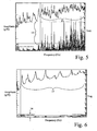
- Figure 7 demonstrates a Frequency-Response-Function (FRF) ensemble of the same thin-walled cylindrical component 10 shown in Figure 1 , measured with shaker excitation, but wherein the adaptive fixture 100 of the present invention is applied, with inflation pressure set as 2.0 Bar.
- FPF Frequency-Response-Function
- the Vibration-Amplitude-Ratio should be in the range of R H ⁇ 2.5, for all the thin-walled shell/cylindrical components with the fixture applied, as defined.
- Figure 8 demonstrates a set of static loading test results respectively from the same thin-walled cylindrical component 10 with adaptive fixture applied, as shown in Figure 1 .
- These are in terms of pneumatic tubes 8 inflated with pressure set as 0.0, 1.0 and 2.0 Bar.
- the Supporting-Rigidity-Ratio should be in the range of K d ⁇ 3.0 , for all the thin-walled shell/cylindrical components with the fixture applied, as defined.
- Loss-Coefficient C d is a general measure for complicated damping effects from engineering structures or materials, statistically, for general thin-walled metallic structure, C d ⁇ 0.001 , and for thin-walled metallic structure with adhered polymeric or elastomeric damping layer, 0.01 ⁇ C d ⁇ 0.1 .
- Loss-Coefficient should be in the range of C d ⁇ 0.1 , for all the thin-walled shell/cylindrical components with the fixture applied, as defined.
- this invention presents an adaptive fixture design approach for thin-walled shell/cylindrical components, for the purpose of enabling them to be machined with sufficient supporting rigidity and dynamic stability, so as to maintain the machining precision and surface finish to an acceptable engineering standard.
- the fixture of the present invention is not limited thereto but can be applied to thick-walled components with advantage. Not only is the fixture adaptive in the sizes of component it can accommodate, but also it is adaptive in its vibration damping characteristic by virtue of the pneumatic pressure.
Landscapes
- Engineering & Computer Science (AREA)
- Mechanical Engineering (AREA)
- Physics & Mathematics (AREA)
- General Physics & Mathematics (AREA)
- Vibration Prevention Devices (AREA)
- Jigs For Machine Tools (AREA)
- Joining Of Building Structures In Genera (AREA)
- Rigid Pipes And Flexible Pipes (AREA)
- Laminated Bodies (AREA)
- Slide Fasteners, Snap Fasteners, And Hook Fasteners (AREA)
- Dowels (AREA)
- Clamps And Clips (AREA)
Applications Claiming Priority (2)
| Application Number | Priority Date | Filing Date | Title |
|---|---|---|---|
| GB0704298A GB2447278B (en) | 2007-03-06 | 2007-03-06 | Adaptive design of fixture for thin-walled shell/cylindrical components |
| PCT/GB2008/000745 WO2008107672A1 (en) | 2007-03-06 | 2008-03-05 | Adaptive design of fixture for thin-walled shell/cylindrical components |
Publications (2)
| Publication Number | Publication Date |
|---|---|
| EP2131998A1 EP2131998A1 (en) | 2009-12-16 |
| EP2131998B1 true EP2131998B1 (en) | 2011-08-17 |
Family
ID=37966005
Family Applications (1)
| Application Number | Title | Priority Date | Filing Date |
|---|---|---|---|
| EP08718606A Not-in-force EP2131998B1 (en) | 2007-03-06 | 2008-03-05 | Adaptive design of fixture for thin-walled shell/cylindrical components |
Country Status (11)
| Country | Link |
|---|---|
| US (2) | US20100164187A1 (https=) |
| EP (1) | EP2131998B1 (https=) |
| JP (1) | JP5539736B2 (https=) |
| KR (1) | KR20090125812A (https=) |
| CN (1) | CN101663129B (https=) |
| AT (1) | ATE520498T1 (https=) |
| AU (1) | AU2008223652B2 (https=) |
| DK (1) | DK2131998T3 (https=) |
| ES (1) | ES2371692T3 (https=) |
| GB (1) | GB2447278B (https=) |
| WO (1) | WO2008107672A1 (https=) |
Cited By (1)
| Publication number | Priority date | Publication date | Assignee | Title |
|---|---|---|---|---|
| CN109202502A (zh) * | 2018-10-25 | 2019-01-15 | 西安航天发动机有限公司 | 一种发动机扩张段铣槽夹具及使用方法 |
Families Citing this family (66)
| Publication number | Priority date | Publication date | Assignee | Title |
|---|---|---|---|---|
| US8695312B2 (en) * | 2008-05-28 | 2014-04-15 | Lantech.Com, Llc | Film clamp and related methods and apparatuses for wrapping loads |
| KR100986082B1 (ko) * | 2008-11-03 | 2010-10-07 | 현대자동차주식회사 | 가변형 클램프 장치 |
| GB0902791D0 (en) * | 2009-02-20 | 2009-04-08 | Rolls Royce Plc | Fixture for securing a thin-walled component |
| GB0902790D0 (en) * | 2009-02-20 | 2009-04-08 | Rolls Royce Plc | Fixture for securing a thin-walled component |
| GB2468488A (en) | 2009-03-09 | 2010-09-15 | Univ Sheffield | Open Squeeze Film Damping System |
| US9079674B1 (en) | 2009-09-18 | 2015-07-14 | Blue Origin, Llc | Composite structures for aerospace vehicles, and associated systems and methods |
| FR2971957B1 (fr) * | 2011-02-28 | 2014-06-13 | Snecma | Amortissement des vibrations generees lors du tournage de tambours de compresseurs de turbomachines |
| US8534530B2 (en) | 2011-04-27 | 2013-09-17 | Blue Origin, Llc | Inflatable ring for supporting friction welding workpieces, and associated systems and methods |
| CN102310032B (zh) * | 2011-09-29 | 2013-01-23 | 哈尔滨建成集团有限公司 | 内锥面类零件吊挂装置 |
| FR2987297B1 (fr) * | 2012-02-27 | 2014-03-28 | Dassault Aviat | Procede d'usinage d'une piece d'une plateforme et dispositif d'usinage associe |
| CN102672540B (zh) * | 2012-05-11 | 2014-10-08 | 北京航空航天大学 | 一种基于dsp航空薄壁盘类件表面形貌测量与夹具加工系统 |
| CN102780135B (zh) * | 2012-07-30 | 2014-12-17 | 上海宇航系统工程研究所 | 四自由度电连接器安装调节装置 |
| CN103056685B (zh) * | 2012-12-26 | 2015-01-28 | 南车石家庄车辆有限公司 | K2旁承座轴槽铣削加工专用工装 |
| US9463541B2 (en) * | 2013-03-08 | 2016-10-11 | Bell Helicopter Textron Inc. | Selectively compliant clamp |
| CN103706809B (zh) * | 2013-12-14 | 2015-11-18 | 山西江淮重工有限责任公司 | 大型薄壁锥形筒加工工装及其加工工艺 |
| GB201402290D0 (en) | 2014-02-11 | 2014-03-26 | Rolls Royce Plc | Fixture |
| ES2489442B1 (es) * | 2014-03-25 | 2015-04-28 | Talleres Lujambio, S.L. | Sistema anti-cimbreo para el mecanizado de ejes huecos |
| CN104084813B (zh) * | 2014-06-30 | 2016-04-27 | 四川高龙机械有限公司 | 一种加工小角度斜圆柱类薄壁零件的方法及辅助工装 |
| CN104384946A (zh) * | 2014-09-11 | 2015-03-04 | 上海航天精密机械研究所 | 一种适用于运载火箭贮箱壁板铣切的装夹装置 |
| GB201420246D0 (en) | 2014-11-14 | 2014-12-31 | Rolls Royce Plc | Apparatus for damping machining vibrations |
| GB201501461D0 (en) | 2015-01-29 | 2015-03-18 | Rolls Royce Plc | Apparatus for damping machining vibration of an object |
| CN105108514A (zh) * | 2015-09-07 | 2015-12-02 | 苏州莱测检测科技有限公司 | 一种圆柱夹紧治具 |
| CN105619145B (zh) * | 2015-12-28 | 2017-11-03 | 哈尔滨工业大学 | 用于保形整流罩外表面精密加工的装夹装置及装夹方法 |
| CN105598879B (zh) * | 2016-02-04 | 2018-07-03 | 杭州奥普特光学有限公司 | 用于精密棒状物的夹持机构 |
| CN105690155A (zh) * | 2016-03-31 | 2016-06-22 | 苏州市合叶精密机械有限公司 | 一种柔性夹具 |
| CN105855947A (zh) * | 2016-06-01 | 2016-08-17 | 昆山科森科技股份有限公司 | 一种异形件固定治具 |
| CN105818074A (zh) * | 2016-06-02 | 2016-08-03 | 苏州工业职业技术学院 | 一种工件的夹持装置 |
| CN106425303B (zh) * | 2016-10-28 | 2019-07-26 | 航天科工哈尔滨风华有限公司 | 一种大型薄壁舱段壳体加工方法及夹具 |
| CN106514152B (zh) * | 2016-12-07 | 2018-11-27 | 贵州黎阳航空动力有限公司 | 一种薄壁多肋钛合金零件的加工方法 |
| CN106926037B (zh) * | 2017-03-16 | 2020-05-19 | 华中科技大学 | 一种适用于复杂曲面加工的夹具及其使用方法 |
| KR102282474B1 (ko) | 2017-06-15 | 2021-07-27 | 한화에어로스페이스 주식회사 | 박벽 부품 고정장치 |
| CN107414556B (zh) * | 2017-09-19 | 2024-01-02 | 菲斯达精密工业部件(苏州)有限公司 | 一种双工位夹具装置 |
| TWI630071B (zh) * | 2017-10-20 | 2018-07-21 | 財團法人工業技術研究院 | 薄型工件夾具 |
| US11400553B2 (en) * | 2017-12-15 | 2022-08-02 | The Boeing Company | Tube fixture and system |
| PL424658A1 (pl) * | 2018-02-22 | 2019-04-08 | Politechnika Gdańska | Sposób doboru optymalnego docisku mocowania podatnego przedmiotu obrabianego zwłaszcza przy frezowaniu czołowym |
| CN108481052A (zh) * | 2018-03-23 | 2018-09-04 | 西安交通大学 | 一种薄壁机匣类零件无颤振加工方法及其加工夹具 |
| CN108436523B (zh) * | 2018-04-27 | 2024-05-10 | 吴江市天龙机械有限公司 | 薄壁球形工件加工用油脂支撑定位装置 |
| CN109539906A (zh) * | 2018-11-29 | 2019-03-29 | 天津航天瑞莱科技有限公司 | 应用于战斗部ct的检测夹具 |
| TWI696577B (zh) | 2018-11-30 | 2020-06-21 | 財團法人工業技術研究院 | 夾持裝置及應用其之夾持系統 |
| US12330214B1 (en) | 2019-02-11 | 2025-06-17 | Blue Origin Manufacturing, LLC | Printed porous media, such as for use in aerospace parts, and associated systems and methods |
| WO2020216074A1 (zh) | 2019-04-23 | 2020-10-29 | 苏州软体机器人科技有限公司 | 一种外夹式夹具 |
| CN110153782A (zh) * | 2019-06-03 | 2019-08-23 | 中国航发航空科技股份有限公司 | 一种用于航空发动机薄壁机匣零件内型加工的减振装置 |
| CN110153760A (zh) * | 2019-06-03 | 2019-08-23 | 中国航发航空科技股份有限公司 | 一种用于航空发动机环形机匣零件外型加工的减振装置 |
| CN110153783B (zh) * | 2019-06-13 | 2021-12-10 | 中国航发航空科技股份有限公司 | 用于吸收机械加工时震动的减震单元装置 |
| CN110340379A (zh) * | 2019-07-18 | 2019-10-18 | 佛山科学技术学院 | 一种球阀芯半加工装置 |
| CN110561270B (zh) * | 2019-08-27 | 2022-05-13 | 中国航空工业集团公司金城南京机电液压工程研究中心 | 一种防止大直径薄壁零件内孔珩磨变形的辅助工装 |
| CN110732691A (zh) * | 2019-11-18 | 2020-01-31 | 中国航发贵州黎阳航空动力有限公司 | 薄壁大盘类零件加工防振刀的方法 |
| CN111112947A (zh) * | 2019-12-02 | 2020-05-08 | 西安航天发动机有限公司 | 一种发动机扩张段ii段铣槽装置 |
| CN112893961B (zh) * | 2019-12-04 | 2023-10-03 | 常德市嘉惠液压机械有限公司 | 一种利用膨胀气囊固定的机械加工设备 |
| CN111941120A (zh) * | 2020-06-11 | 2020-11-17 | 上海航天设备制造总厂有限公司 | 环形薄壁件加工自动装夹系统 |
| CN112571089A (zh) * | 2020-11-19 | 2021-03-30 | 首都航天机械有限公司 | 一种整体旋压类半球壳体点阵式柔性固定支撑装置 |
| US11666998B2 (en) * | 2020-11-24 | 2023-06-06 | GM Global Technology Operations LLC | Rigid insert shape control in layer jammming systems and methods |
| EP4059631B1 (de) * | 2021-03-17 | 2025-10-29 | HINTERKOPF GmbH | Greifeinrichtung |
| CN214450005U (zh) * | 2021-03-18 | 2021-10-22 | 袁海海 | 弹性薄壁壳车轮及具有该车轮的车辆 |
| CN113547429B (zh) * | 2021-07-13 | 2022-05-10 | 阜阳万瑞斯电子锁业有限公司 | 一种智能锁壳体加工装置 |
| CN113523854B (zh) * | 2021-07-30 | 2022-09-27 | 西北机器有限公司 | 一种薄壁回转曲面零件的加工工装及加工方法 |
| CN114161177A (zh) * | 2021-12-02 | 2022-03-11 | 首都航天机械有限公司 | 一种薄壁曲面零件的定位装夹方法 |
| CN114952589B (zh) * | 2022-05-30 | 2023-11-03 | 马鞍山市龙腾机电科技有限公司 | 一种直槽散热型铸造电机外壳的去毛刺打磨装置 |
| CN116618725B (zh) * | 2023-03-10 | 2026-02-10 | 北京星航机电装备有限公司 | 筒形薄壁零件的加工方法及加工模具 |
| CN117415652B (zh) * | 2023-11-10 | 2025-08-29 | 大连理工大学 | 一种带有翻边零件的低应力柔性装夹装置及装夹方法 |
| CN117718851B (zh) * | 2023-11-10 | 2026-04-10 | 大连理工大学 | 一种大口径复合材料天线反射面原位磨抛装置及方法 |
| CN117644411A (zh) * | 2023-11-23 | 2024-03-05 | 山西江淮重工有限责任公司 | 用于异形薄壁产品的铣削固定装置及铣削方法 |
| CN117754031A (zh) * | 2023-11-28 | 2024-03-26 | 上海交通大学 | 一种复合材料叶片钛合金包边的铣削加工方法 |
| CN117773610A (zh) * | 2024-02-02 | 2024-03-29 | 上海睿昇半导体科技有限公司 | 适用于薄壁盘类零件的夹持工装及夹持方法 |
| CN117773625A (zh) * | 2024-02-06 | 2024-03-29 | 仪征海天铝业有限公司 | 一种用于铝型材加工的装夹工装 |
| CN119567131B (zh) * | 2024-11-19 | 2025-09-16 | 北京航空航天大学 | 薄壁工件装夹工装 |
Family Cites Families (36)
| Publication number | Priority date | Publication date | Assignee | Title |
|---|---|---|---|---|
| USRE24842E (en) * | 1960-06-28 | gunther | ||
| US2534527A (en) * | 1948-05-04 | 1950-12-19 | Herman A Myers | Work holder |
| LU31181A1 (https=) * | 1950-02-10 | |||
| US2826420A (en) * | 1954-01-08 | 1958-03-11 | Karl A Klingler | Hydraulic holding means for chucks and the like |
| US3023995A (en) * | 1958-07-21 | 1962-03-06 | William C N Hopkins | Sealing and coupling structures |
| US3147017A (en) * | 1962-09-05 | 1964-09-01 | Dunham Tool Company Inc | Vacuum gripper |
| US3233315A (en) * | 1962-12-04 | 1966-02-08 | Plastic Materials Inc | Pipe aligning and joining apparatus |
| US3420538A (en) * | 1966-01-21 | 1969-01-07 | Erickson Tool Co | Swivel finger chuck |
| US3542354A (en) * | 1968-06-12 | 1970-11-24 | Micromatic Hone Corp | Nondistortive work holding fixture |
| US3663027A (en) * | 1970-09-14 | 1972-05-16 | Ingersoll Milling Machine Co | Fluid actuated clamp |
| DE2218561C3 (de) * | 1972-04-17 | 1978-04-27 | Uniroyal Ag, 5100 Aachen | Aufnahmedorn für Vorrichtungen zum Abstechen von Ringen von eine undehnbare Einlage aufweisenden Schläuchen oder Rohren aus Gummi, Kunststoff oder ähnlichem Material |
| FR2237729B1 (https=) * | 1973-07-20 | 1976-11-12 | Citroen Sa | |
| DE2845056A1 (de) | 1978-10-16 | 1980-04-30 | Freudenberg Carl Fa | Spannvorrichtung |
| US4465220A (en) * | 1979-11-05 | 1984-08-14 | The Boeing Company | Device for supporting weld underbead |
| IT1149490B (it) * | 1982-01-27 | 1986-12-03 | Giovanni Gattrugeri | Testata espandibile per bobine in genere |
| US4811962A (en) * | 1984-11-23 | 1989-03-14 | Cameron Jr G N | Holder for machining thin walled cylinder |
| JPS63154131U (https=) * | 1987-03-27 | 1988-10-11 | ||
| US4840323A (en) * | 1988-02-08 | 1989-06-20 | Kiyoji Nakajima | Web winding and/or rewinding shaft structure |
| US4953877A (en) * | 1988-09-23 | 1990-09-04 | Gene Slachta | Fluid actuated chuck |
| US5127554A (en) * | 1989-05-19 | 1992-07-07 | Nozone Dispenser Systems Inc. | Aerosol power system |
| US5404946A (en) * | 1993-08-02 | 1995-04-11 | The United States Of America As Represented By The Secretary Of The Interior | Wireline-powered inflatable-packer system for deep wells |
| JP2003522550A (ja) * | 1998-02-10 | 2003-07-29 | アーテミス・メディカル・インコーポレイテッド | 咬合、固定、テンショニング、及び流向装置とその使用方法 |
| US6015154A (en) * | 1998-05-28 | 2000-01-18 | Hydra-Lock Corporation | Large displacement hydrostatic workpiece holder |
| US6145849A (en) * | 1998-11-18 | 2000-11-14 | Komag, Incorporated | Disk processing chuck |
| US6164351A (en) * | 2000-01-05 | 2000-12-26 | Triangle Pacific Corporation | Precision-balanced cutter head and method |
| DE10037187C2 (de) * | 2000-07-31 | 2002-06-13 | Schmalz J Gmbh | Haltevorrichtung |
| TW484617U (en) * | 2001-05-15 | 2002-04-21 | Shi-Tsai Chen | Pneumatic cover clip |
| EP1384576B1 (en) * | 2002-07-25 | 2005-11-09 | Cryovac, Inc. | Gas-barrier thermoplastic film and substrate/film composite material |
| CN2600213Y (zh) * | 2002-12-27 | 2004-01-21 | 宁夏回族自治区大河机床厂一厂 | 薄壁套加工用弹性夹具 |
| US7147232B2 (en) * | 2003-06-30 | 2006-12-12 | Hydra-Lock Corporation | Workpiece holder |
| DE50302513D1 (de) * | 2003-11-05 | 2006-04-27 | Schunk Gmbh & Co Kg | Dehnspanneinrichtung |
| DE102004010987B4 (de) * | 2004-03-03 | 2013-08-22 | Klaus Hofmann | Sicherungseinheit |
| US7316403B2 (en) * | 2004-12-22 | 2008-01-08 | Hydra Lock Corp | Hydrostatic workpiece holder with a removable cartridge assembly |
| US7331583B1 (en) * | 2004-12-22 | 2008-02-19 | Hydra-Lock Corporation | Workpiece holder with a multi-piece bladder |
| GB0902791D0 (en) * | 2009-02-20 | 2009-04-08 | Rolls Royce Plc | Fixture for securing a thin-walled component |
| US8281659B2 (en) * | 2009-07-15 | 2012-10-09 | Ata Engineering, Inc. | Methods and apparatus for vibration testing using multiple sine sweep excitation |
-
2007
- 2007-03-06 GB GB0704298A patent/GB2447278B/en active Active
-
2008
- 2008-03-05 JP JP2009552269A patent/JP5539736B2/ja not_active Expired - Fee Related
- 2008-03-05 ES ES08718606T patent/ES2371692T3/es active Active
- 2008-03-05 US US12/529,834 patent/US20100164187A1/en not_active Abandoned
- 2008-03-05 EP EP08718606A patent/EP2131998B1/en not_active Not-in-force
- 2008-03-05 WO PCT/GB2008/000745 patent/WO2008107672A1/en not_active Ceased
- 2008-03-05 AU AU2008223652A patent/AU2008223652B2/en not_active Ceased
- 2008-03-05 KR KR1020097020862A patent/KR20090125812A/ko not_active Abandoned
- 2008-03-05 CN CN2008800073630A patent/CN101663129B/zh not_active Expired - Fee Related
- 2008-03-05 AT AT08718606T patent/ATE520498T1/de not_active IP Right Cessation
- 2008-03-05 DK DK08718606.0T patent/DK2131998T3/da active
-
2014
- 2014-03-24 US US14/223,076 patent/US20140283368A1/en not_active Abandoned
Cited By (1)
| Publication number | Priority date | Publication date | Assignee | Title |
|---|---|---|---|---|
| CN109202502A (zh) * | 2018-10-25 | 2019-01-15 | 西安航天发动机有限公司 | 一种发动机扩张段铣槽夹具及使用方法 |
Also Published As
| Publication number | Publication date |
|---|---|
| CN101663129A (zh) | 2010-03-03 |
| GB0704298D0 (en) | 2007-04-11 |
| EP2131998A1 (en) | 2009-12-16 |
| US20100164187A1 (en) | 2010-07-01 |
| GB2447278A (en) | 2008-09-10 |
| DK2131998T3 (da) | 2011-11-21 |
| AU2008223652B2 (en) | 2012-08-30 |
| ES2371692T3 (es) | 2012-01-09 |
| AU2008223652A1 (en) | 2008-09-12 |
| US20140283368A1 (en) | 2014-09-25 |
| KR20090125812A (ko) | 2009-12-07 |
| ATE520498T1 (de) | 2011-09-15 |
| JP2010520074A (ja) | 2010-06-10 |
| GB2447278B (en) | 2011-12-07 |
| CN101663129B (zh) | 2013-06-12 |
| WO2008107672A1 (en) | 2008-09-12 |
| JP5539736B2 (ja) | 2014-07-02 |
Similar Documents
| Publication | Publication Date | Title |
|---|---|---|
| EP2131998B1 (en) | Adaptive design of fixture for thin-walled shell/cylindrical components | |
| JP5829126B2 (ja) | 薄壁包囲要素を固定するための固定治具 | |
| EP2398622B1 (en) | Fixture for securing a thin-walled component comprising a liner having a stiffening element | |
| US11542570B2 (en) | Device and a method for reducing and homogenizing residual stress of a workpiece generated during machining | |
| US7631408B2 (en) | Method of manufacturing thin wall isogrid casings | |
| JP7212048B2 (ja) | 減衰装置を含むツールボディ及びそのようなツールボディを有する加工ツール | |
| CN104759653B (zh) | 用于薄壁筒体类零件的加工工装 | |
| JPH03180223A (ja) | 成形ダイスとダイスの製作方法 | |
| US20170292584A1 (en) | Damping apparatus | |
| JP2003194019A (ja) | クランプ装置 | |
| CN113843638B (zh) | 一种提高薄壁零件加工稳定性的方法及应用 | |
| JP5883407B2 (ja) | 位置調整用治具、それを含むチャック装置を備えた工作機械、それを含むチャック装置を備えた検査器、および、それに用いられる可変形部材 | |
| Yamnikov et al. | Elements of Vibration-Damping Mandrels | |
| RU2777079C1 (ru) | Инструментальная оправка с повышенной жесткостью и виброустойчивостью | |
| RU192909U1 (ru) | Приспособление для закрепления цилиндрических деталей | |
| RU2616738C2 (ru) | Оправка для закрепления тонкостенной детали при прецизионном шлифовании | |
| JP6347837B2 (ja) | 旋盤 | |
| JP2008018474A (ja) | 筒状被加工物の固定装置 |
Legal Events
| Date | Code | Title | Description |
|---|---|---|---|
| PUAI | Public reference made under article 153(3) epc to a published international application that has entered the european phase |
Free format text: ORIGINAL CODE: 0009012 |
|
| 17P | Request for examination filed |
Effective date: 20090922 |
|
| AK | Designated contracting states |
Kind code of ref document: A1 Designated state(s): AT BE BG CH CY CZ DE DK EE ES FI FR GB GR HR HU IE IS IT LI LT LU LV MC MT NL NO PL PT RO SE SI SK TR |
|
| 17Q | First examination report despatched |
Effective date: 20100407 |
|
| DAX | Request for extension of the european patent (deleted) | ||
| GRAP | Despatch of communication of intention to grant a patent |
Free format text: ORIGINAL CODE: EPIDOSNIGR1 |
|
| RIN1 | Information on inventor provided before grant (corrected) |
Inventor name: GENG, ZUNMIN |
|
| GRAS | Grant fee paid |
Free format text: ORIGINAL CODE: EPIDOSNIGR3 |
|
| GRAA | (expected) grant |
Free format text: ORIGINAL CODE: 0009210 |
|
| AK | Designated contracting states |
Kind code of ref document: B1 Designated state(s): AT BE BG CH CY CZ DE DK EE ES FI FR GB GR HR HU IE IS IT LI LT LU LV MC MT NL NO PL PT RO SE SI SK TR |
|
| REG | Reference to a national code |
Ref country code: GB Ref legal event code: FG4D |
|
| REG | Reference to a national code |
Ref country code: CH Ref legal event code: EP |
|
| REG | Reference to a national code |
Ref country code: IE Ref legal event code: FG4D |
|
| REG | Reference to a national code |
Ref country code: DE Ref legal event code: R096 Ref document number: 602008008943 Country of ref document: DE Effective date: 20111020 |
|
| REG | Reference to a national code |
Ref country code: NL Ref legal event code: T3 |
|
| REG | Reference to a national code |
Ref country code: DK Ref legal event code: T3 |
|
| REG | Reference to a national code |
Ref country code: SE Ref legal event code: TRGR |
|
| REG | Reference to a national code |
Ref country code: NO Ref legal event code: T2 Effective date: 20110817 |
|
| REG | Reference to a national code |
Ref country code: ES Ref legal event code: FG2A Ref document number: 2371692 Country of ref document: ES Kind code of ref document: T3 Effective date: 20120109 |
|
| LTIE | Lt: invalidation of european patent or patent extension |
Effective date: 20110817 |
|
| PG25 | Lapsed in a contracting state [announced via postgrant information from national office to epo] |
Ref country code: PT Free format text: LAPSE BECAUSE OF FAILURE TO SUBMIT A TRANSLATION OF THE DESCRIPTION OR TO PAY THE FEE WITHIN THE PRESCRIBED TIME-LIMIT Effective date: 20111219 Ref country code: LT Free format text: LAPSE BECAUSE OF FAILURE TO SUBMIT A TRANSLATION OF THE DESCRIPTION OR TO PAY THE FEE WITHIN THE PRESCRIBED TIME-LIMIT Effective date: 20110817 Ref country code: FI Free format text: LAPSE BECAUSE OF FAILURE TO SUBMIT A TRANSLATION OF THE DESCRIPTION OR TO PAY THE FEE WITHIN THE PRESCRIBED TIME-LIMIT Effective date: 20110817 Ref country code: IS Free format text: LAPSE BECAUSE OF FAILURE TO SUBMIT A TRANSLATION OF THE DESCRIPTION OR TO PAY THE FEE WITHIN THE PRESCRIBED TIME-LIMIT Effective date: 20111217 |
|
| REG | Reference to a national code |
Ref country code: AT Ref legal event code: MK05 Ref document number: 520498 Country of ref document: AT Kind code of ref document: T Effective date: 20110817 |
|
| PG25 | Lapsed in a contracting state [announced via postgrant information from national office to epo] |
Ref country code: SI Free format text: LAPSE BECAUSE OF FAILURE TO SUBMIT A TRANSLATION OF THE DESCRIPTION OR TO PAY THE FEE WITHIN THE PRESCRIBED TIME-LIMIT Effective date: 20110817 Ref country code: PL Free format text: LAPSE BECAUSE OF FAILURE TO SUBMIT A TRANSLATION OF THE DESCRIPTION OR TO PAY THE FEE WITHIN THE PRESCRIBED TIME-LIMIT Effective date: 20110817 Ref country code: CY Free format text: LAPSE BECAUSE OF FAILURE TO SUBMIT A TRANSLATION OF THE DESCRIPTION OR TO PAY THE FEE WITHIN THE PRESCRIBED TIME-LIMIT Effective date: 20110817 Ref country code: AT Free format text: LAPSE BECAUSE OF FAILURE TO SUBMIT A TRANSLATION OF THE DESCRIPTION OR TO PAY THE FEE WITHIN THE PRESCRIBED TIME-LIMIT Effective date: 20110817 Ref country code: GR Free format text: LAPSE BECAUSE OF FAILURE TO SUBMIT A TRANSLATION OF THE DESCRIPTION OR TO PAY THE FEE WITHIN THE PRESCRIBED TIME-LIMIT Effective date: 20111118 Ref country code: LV Free format text: LAPSE BECAUSE OF FAILURE TO SUBMIT A TRANSLATION OF THE DESCRIPTION OR TO PAY THE FEE WITHIN THE PRESCRIBED TIME-LIMIT Effective date: 20110817 |
|
| PG25 | Lapsed in a contracting state [announced via postgrant information from national office to epo] |
Ref country code: SK Free format text: LAPSE BECAUSE OF FAILURE TO SUBMIT A TRANSLATION OF THE DESCRIPTION OR TO PAY THE FEE WITHIN THE PRESCRIBED TIME-LIMIT Effective date: 20110817 |
|
| PG25 | Lapsed in a contracting state [announced via postgrant information from national office to epo] |
Ref country code: RO Free format text: LAPSE BECAUSE OF FAILURE TO SUBMIT A TRANSLATION OF THE DESCRIPTION OR TO PAY THE FEE WITHIN THE PRESCRIBED TIME-LIMIT Effective date: 20110817 Ref country code: EE Free format text: LAPSE BECAUSE OF FAILURE TO SUBMIT A TRANSLATION OF THE DESCRIPTION OR TO PAY THE FEE WITHIN THE PRESCRIBED TIME-LIMIT Effective date: 20110817 |
|
| PGFP | Annual fee paid to national office [announced via postgrant information from national office to epo] |
Ref country code: TR Payment date: 20120302 Year of fee payment: 5 |
|
| PLBE | No opposition filed within time limit |
Free format text: ORIGINAL CODE: 0009261 |
|
| STAA | Information on the status of an ep patent application or granted ep patent |
Free format text: STATUS: NO OPPOSITION FILED WITHIN TIME LIMIT |
|
| PGFP | Annual fee paid to national office [announced via postgrant information from national office to epo] |
Ref country code: IT Payment date: 20120323 Year of fee payment: 5 |
|
| 26N | No opposition filed |
Effective date: 20120521 |
|
| PG25 | Lapsed in a contracting state [announced via postgrant information from national office to epo] |
Ref country code: HR Free format text: LAPSE BECAUSE OF FAILURE TO SUBMIT A TRANSLATION OF THE DESCRIPTION OR TO PAY THE FEE WITHIN THE PRESCRIBED TIME-LIMIT Effective date: 20120328 |
|
| REG | Reference to a national code |
Ref country code: DE Ref legal event code: R097 Ref document number: 602008008943 Country of ref document: DE Effective date: 20120521 |
|
| PG25 | Lapsed in a contracting state [announced via postgrant information from national office to epo] |
Ref country code: MC Free format text: LAPSE BECAUSE OF NON-PAYMENT OF DUE FEES Effective date: 20120331 |
|
| REG | Reference to a national code |
Ref country code: IE Ref legal event code: MM4A |
|
| PG25 | Lapsed in a contracting state [announced via postgrant information from national office to epo] |
Ref country code: IE Free format text: LAPSE BECAUSE OF NON-PAYMENT OF DUE FEES Effective date: 20120305 |
|
| PGFP | Annual fee paid to national office [announced via postgrant information from national office to epo] |
Ref country code: DK Payment date: 20130325 Year of fee payment: 6 Ref country code: CH Payment date: 20130320 Year of fee payment: 6 Ref country code: SE Payment date: 20130322 Year of fee payment: 6 Ref country code: ES Payment date: 20130326 Year of fee payment: 6 Ref country code: FR Payment date: 20130409 Year of fee payment: 6 Ref country code: CZ Payment date: 20130304 Year of fee payment: 6 Ref country code: NO Payment date: 20130322 Year of fee payment: 6 Ref country code: DE Payment date: 20130322 Year of fee payment: 6 |
|
| PG25 | Lapsed in a contracting state [announced via postgrant information from national office to epo] |
Ref country code: BG Free format text: LAPSE BECAUSE OF FAILURE TO SUBMIT A TRANSLATION OF THE DESCRIPTION OR TO PAY THE FEE WITHIN THE PRESCRIBED TIME-LIMIT Effective date: 20111117 |
|
| PG25 | Lapsed in a contracting state [announced via postgrant information from national office to epo] |
Ref country code: MT Free format text: LAPSE BECAUSE OF FAILURE TO SUBMIT A TRANSLATION OF THE DESCRIPTION OR TO PAY THE FEE WITHIN THE PRESCRIBED TIME-LIMIT Effective date: 20110817 |
|
| PGFP | Annual fee paid to national office [announced via postgrant information from national office to epo] |
Ref country code: BE Payment date: 20130409 Year of fee payment: 6 |
|
| PGFP | Annual fee paid to national office [announced via postgrant information from national office to epo] |
Ref country code: NL Payment date: 20130321 Year of fee payment: 6 |
|
| PG25 | Lapsed in a contracting state [announced via postgrant information from national office to epo] |
Ref country code: HR Free format text: LAPSE BECAUSE OF FAILURE TO SUBMIT A TRANSLATION OF THE DESCRIPTION OR TO PAY THE FEE WITHIN THE PRESCRIBED TIME-LIMIT Effective date: 20110817 |
|
| PG25 | Lapsed in a contracting state [announced via postgrant information from national office to epo] |
Ref country code: LU Free format text: LAPSE BECAUSE OF NON-PAYMENT OF DUE FEES Effective date: 20120305 |
|
| REG | Reference to a national code |
Ref country code: NO Ref legal event code: MH4A Effective date: 20140721 |
|
| PG25 | Lapsed in a contracting state [announced via postgrant information from national office to epo] |
Ref country code: HU Free format text: LAPSE BECAUSE OF FAILURE TO SUBMIT A TRANSLATION OF THE DESCRIPTION OR TO PAY THE FEE WITHIN THE PRESCRIBED TIME-LIMIT Effective date: 20080305 |
|
| REG | Reference to a national code |
Ref country code: DE Ref legal event code: R119 Ref document number: 602008008943 Country of ref document: DE |
|
| REG | Reference to a national code |
Ref country code: DK Ref legal event code: EBP Effective date: 20140331 |
|
| REG | Reference to a national code |
Ref country code: NL Ref legal event code: V1 Effective date: 20141001 |
|
| PG25 | Lapsed in a contracting state [announced via postgrant information from national office to epo] |
Ref country code: CZ Free format text: LAPSE BECAUSE OF NON-PAYMENT OF DUE FEES Effective date: 20140305 |
|
| REG | Reference to a national code |
Ref country code: CH Ref legal event code: PL |
|
| REG | Reference to a national code |
Ref country code: SE Ref legal event code: EUG |
|
| PG25 | Lapsed in a contracting state [announced via postgrant information from national office to epo] |
Ref country code: SE Free format text: LAPSE BECAUSE OF NON-PAYMENT OF DUE FEES Effective date: 20140306 |
|
| REG | Reference to a national code |
Ref country code: FR Ref legal event code: ST Effective date: 20141128 |
|
| REG | Reference to a national code |
Ref country code: DE Ref legal event code: R119 Ref document number: 602008008943 Country of ref document: DE Effective date: 20141001 |
|
| PG25 | Lapsed in a contracting state [announced via postgrant information from national office to epo] |
Ref country code: DE Free format text: LAPSE BECAUSE OF NON-PAYMENT OF DUE FEES Effective date: 20141001 Ref country code: CH Free format text: LAPSE BECAUSE OF NON-PAYMENT OF DUE FEES Effective date: 20140331 Ref country code: LI Free format text: LAPSE BECAUSE OF NON-PAYMENT OF DUE FEES Effective date: 20140331 Ref country code: FR Free format text: LAPSE BECAUSE OF NON-PAYMENT OF DUE FEES Effective date: 20140331 |
|
| PG25 | Lapsed in a contracting state [announced via postgrant information from national office to epo] |
Ref country code: NL Free format text: LAPSE BECAUSE OF NON-PAYMENT OF DUE FEES Effective date: 20141001 |
|
| PG25 | Lapsed in a contracting state [announced via postgrant information from national office to epo] |
Ref country code: IT Free format text: LAPSE BECAUSE OF NON-PAYMENT OF DUE FEES Effective date: 20140305 |
|
| PG25 | Lapsed in a contracting state [announced via postgrant information from national office to epo] |
Ref country code: DK Free format text: LAPSE BECAUSE OF NON-PAYMENT OF DUE FEES Effective date: 20140331 |
|
| REG | Reference to a national code |
Ref country code: ES Ref legal event code: FD2A Effective date: 20151027 |
|
| PG25 | Lapsed in a contracting state [announced via postgrant information from national office to epo] |
Ref country code: ES Free format text: LAPSE BECAUSE OF NON-PAYMENT OF DUE FEES Effective date: 20140306 |
|
| PG25 | Lapsed in a contracting state [announced via postgrant information from national office to epo] |
Ref country code: NO Free format text: LAPSE BECAUSE OF THE APPLICANT RENOUNCES Effective date: 20140701 |
|
| PG25 | Lapsed in a contracting state [announced via postgrant information from national office to epo] |
Ref country code: BE Free format text: LAPSE BECAUSE OF NON-PAYMENT OF DUE FEES Effective date: 20140331 |
|
| PG25 | Lapsed in a contracting state [announced via postgrant information from national office to epo] |
Ref country code: TR Free format text: LAPSE BECAUSE OF NON-PAYMENT OF DUE FEES Effective date: 20140305 |
|
| PGFP | Annual fee paid to national office [announced via postgrant information from national office to epo] |
Ref country code: GB Payment date: 20190102 Year of fee payment: 12 |
|
| GBPC | Gb: european patent ceased through non-payment of renewal fee |
Effective date: 20200305 |
|
| PG25 | Lapsed in a contracting state [announced via postgrant information from national office to epo] |
Ref country code: GB Free format text: LAPSE BECAUSE OF NON-PAYMENT OF DUE FEES Effective date: 20200305 |