EP2130488A1 - Klinisches ohrthermometer und steuerungsverfahren dafür - Google Patents
Klinisches ohrthermometer und steuerungsverfahren dafür Download PDFInfo
- Publication number
- EP2130488A1 EP2130488A1 EP08738652A EP08738652A EP2130488A1 EP 2130488 A1 EP2130488 A1 EP 2130488A1 EP 08738652 A EP08738652 A EP 08738652A EP 08738652 A EP08738652 A EP 08738652A EP 2130488 A1 EP2130488 A1 EP 2130488A1
- Authority
- EP
- European Patent Office
- Prior art keywords
- probe
- detection
- temperature
- cover
- probe cover
- Prior art date
- Legal status (The legal status is an assumption and is not a legal conclusion. Google has not performed a legal analysis and makes no representation as to the accuracy of the status listed.)
- Withdrawn
Links
- 238000000034 method Methods 0.000 title claims description 37
- 239000000523 sample Substances 0.000 claims abstract description 324
- 238000001514 detection method Methods 0.000 claims abstract description 239
- 230000036760 body temperature Effects 0.000 claims abstract description 55
- 238000006243 chemical reaction Methods 0.000 claims abstract description 29
- 239000004973 liquid crystal related substance Substances 0.000 claims abstract description 23
- 230000005855 radiation Effects 0.000 claims abstract description 6
- 238000009529 body temperature measurement Methods 0.000 claims description 26
- 238000012937 correction Methods 0.000 claims description 25
- 238000003860 storage Methods 0.000 claims description 21
- 230000003287 optical effect Effects 0.000 claims description 12
- 238000005259 measurement Methods 0.000 abstract description 33
- 230000008569 process Effects 0.000 description 26
- 238000010586 diagram Methods 0.000 description 8
- 230000037431 insertion Effects 0.000 description 7
- 238000012545 processing Methods 0.000 description 7
- 229920005989 resin Polymers 0.000 description 7
- 239000011347 resin Substances 0.000 description 7
- 239000000463 material Substances 0.000 description 6
- -1 polyethylene Polymers 0.000 description 6
- 238000003825 pressing Methods 0.000 description 6
- 230000000694 effects Effects 0.000 description 4
- 238000003780 insertion Methods 0.000 description 4
- XLYOFNOQVPJJNP-UHFFFAOYSA-N water Substances O XLYOFNOQVPJJNP-UHFFFAOYSA-N 0.000 description 4
- 230000006870 function Effects 0.000 description 3
- 206010050337 Cerumen impaction Diseases 0.000 description 2
- 239000004698 Polyethylene Substances 0.000 description 2
- 239000004743 Polypropylene Substances 0.000 description 2
- 230000009471 action Effects 0.000 description 2
- 229910052782 aluminium Inorganic materials 0.000 description 2
- XAGFODPZIPBFFR-UHFFFAOYSA-N aluminium Chemical compound [Al] XAGFODPZIPBFFR-UHFFFAOYSA-N 0.000 description 2
- 210000002939 cerumen Anatomy 0.000 description 2
- 230000008859 change Effects 0.000 description 2
- 238000004590 computer program Methods 0.000 description 2
- 238000013461 design Methods 0.000 description 2
- 230000005611 electricity Effects 0.000 description 2
- 238000001746 injection moulding Methods 0.000 description 2
- 229910052751 metal Inorganic materials 0.000 description 2
- 239000002184 metal Substances 0.000 description 2
- 229920000573 polyethylene Polymers 0.000 description 2
- 229920001155 polypropylene Polymers 0.000 description 2
- 230000000717 retained effect Effects 0.000 description 2
- LFQSCWFLJHTTHZ-UHFFFAOYSA-N Ethanol Chemical compound CCO LFQSCWFLJHTTHZ-UHFFFAOYSA-N 0.000 description 1
- 238000010521 absorption reaction Methods 0.000 description 1
- 239000000853 adhesive Substances 0.000 description 1
- 230000001070 adhesive effect Effects 0.000 description 1
- 230000004397 blinking Effects 0.000 description 1
- DQXBYHZEEUGOBF-UHFFFAOYSA-N but-3-enoic acid;ethene Chemical compound C=C.OC(=O)CC=C DQXBYHZEEUGOBF-UHFFFAOYSA-N 0.000 description 1
- 229910010293 ceramic material Inorganic materials 0.000 description 1
- 238000004140 cleaning Methods 0.000 description 1
- 239000003086 colorant Substances 0.000 description 1
- 239000004020 conductor Substances 0.000 description 1
- 230000000994 depressogenic effect Effects 0.000 description 1
- 210000000883 ear external Anatomy 0.000 description 1
- 229920006351 engineering plastic Polymers 0.000 description 1
- 239000005038 ethylene vinyl acetate Substances 0.000 description 1
- PCHJSUWPFVWCPO-UHFFFAOYSA-N gold Chemical compound [Au] PCHJSUWPFVWCPO-UHFFFAOYSA-N 0.000 description 1
- 239000010931 gold Substances 0.000 description 1
- 229910052737 gold Inorganic materials 0.000 description 1
- 238000012423 maintenance Methods 0.000 description 1
- 238000004519 manufacturing process Methods 0.000 description 1
- 150000002739 metals Chemical class 0.000 description 1
- 238000000465 moulding Methods 0.000 description 1
- 229920001200 poly(ethylene-vinyl acetate) Polymers 0.000 description 1
- 229920001707 polybutylene terephthalate Polymers 0.000 description 1
- 229920000728 polyester Polymers 0.000 description 1
- 229920000139 polyethylene terephthalate Polymers 0.000 description 1
- 239000005020 polyethylene terephthalate Substances 0.000 description 1
- 229920000642 polymer Polymers 0.000 description 1
- 229920000098 polyolefin Polymers 0.000 description 1
- 238000007789 sealing Methods 0.000 description 1
- 229910001220 stainless steel Inorganic materials 0.000 description 1
- 239000010935 stainless steel Substances 0.000 description 1
- 239000000758 substrate Substances 0.000 description 1
- 230000007704 transition Effects 0.000 description 1
- 238000002834 transmittance Methods 0.000 description 1
- 210000003454 tympanic membrane Anatomy 0.000 description 1
Images


Classifications
-
- G—PHYSICS
- G01—MEASURING; TESTING
- G01J—MEASUREMENT OF INTENSITY, VELOCITY, SPECTRAL CONTENT, POLARISATION, PHASE OR PULSE CHARACTERISTICS OF INFRARED, VISIBLE OR ULTRAVIOLET LIGHT; COLORIMETRY; RADIATION PYROMETRY
- G01J5/00—Radiation pyrometry, e.g. infrared or optical thermometry
- G01J5/02—Constructional details
- G01J5/04—Casings
-
- G—PHYSICS
- G01—MEASURING; TESTING
- G01J—MEASUREMENT OF INTENSITY, VELOCITY, SPECTRAL CONTENT, POLARISATION, PHASE OR PULSE CHARACTERISTICS OF INFRARED, VISIBLE OR ULTRAVIOLET LIGHT; COLORIMETRY; RADIATION PYROMETRY
- G01J5/00—Radiation pyrometry, e.g. infrared or optical thermometry
- G01J5/0003—Radiation pyrometry, e.g. infrared or optical thermometry for sensing the radiant heat transfer of samples, e.g. emittance meter
- G01J5/0011—Ear thermometers
-
- G—PHYSICS
- G01—MEASURING; TESTING
- G01J—MEASUREMENT OF INTENSITY, VELOCITY, SPECTRAL CONTENT, POLARISATION, PHASE OR PULSE CHARACTERISTICS OF INFRARED, VISIBLE OR ULTRAVIOLET LIGHT; COLORIMETRY; RADIATION PYROMETRY
- G01J5/00—Radiation pyrometry, e.g. infrared or optical thermometry
- G01J5/02—Constructional details
- G01J5/021—Probe covers for thermometers, e.g. tympanic thermometers; Containers for probe covers; Disposable probes
-
- G—PHYSICS
- G01—MEASURING; TESTING
- G01J—MEASUREMENT OF INTENSITY, VELOCITY, SPECTRAL CONTENT, POLARISATION, PHASE OR PULSE CHARACTERISTICS OF INFRARED, VISIBLE OR ULTRAVIOLET LIGHT; COLORIMETRY; RADIATION PYROMETRY
- G01J5/00—Radiation pyrometry, e.g. infrared or optical thermometry
- G01J5/02—Constructional details
- G01J5/025—Interfacing a pyrometer to an external device or network; User interface
-
- G—PHYSICS
- G01—MEASURING; TESTING
- G01J—MEASUREMENT OF INTENSITY, VELOCITY, SPECTRAL CONTENT, POLARISATION, PHASE OR PULSE CHARACTERISTICS OF INFRARED, VISIBLE OR ULTRAVIOLET LIGHT; COLORIMETRY; RADIATION PYROMETRY
- G01J5/00—Radiation pyrometry, e.g. infrared or optical thermometry
- G01J5/02—Constructional details
- G01J5/026—Control of working procedures of a pyrometer, other than calibration; Bandwidth calculation; Gain control
-
- G—PHYSICS
- G01—MEASURING; TESTING
- G01J—MEASUREMENT OF INTENSITY, VELOCITY, SPECTRAL CONTENT, POLARISATION, PHASE OR PULSE CHARACTERISTICS OF INFRARED, VISIBLE OR ULTRAVIOLET LIGHT; COLORIMETRY; RADIATION PYROMETRY
- G01J5/00—Radiation pyrometry, e.g. infrared or optical thermometry
- G01J5/02—Constructional details
- G01J5/04—Casings
- G01J5/049—Casings for tympanic thermometers
-
- G—PHYSICS
- G01—MEASURING; TESTING
- G01J—MEASUREMENT OF INTENSITY, VELOCITY, SPECTRAL CONTENT, POLARISATION, PHASE OR PULSE CHARACTERISTICS OF INFRARED, VISIBLE OR ULTRAVIOLET LIGHT; COLORIMETRY; RADIATION PYROMETRY
- G01J5/00—Radiation pyrometry, e.g. infrared or optical thermometry
- G01J5/02—Constructional details
- G01J5/06—Arrangements for eliminating effects of disturbing radiation; Arrangements for compensating changes in sensitivity
- G01J5/064—Ambient temperature sensor; Housing temperature sensor; Constructional details thereof
-
- G—PHYSICS
- G01—MEASURING; TESTING
- G01J—MEASUREMENT OF INTENSITY, VELOCITY, SPECTRAL CONTENT, POLARISATION, PHASE OR PULSE CHARACTERISTICS OF INFRARED, VISIBLE OR ULTRAVIOLET LIGHT; COLORIMETRY; RADIATION PYROMETRY
- G01J5/00—Radiation pyrometry, e.g. infrared or optical thermometry
- G01J5/02—Constructional details
- G01J5/08—Optical arrangements
- G01J5/0893—Arrangements to attach devices to a pyrometer, i.e. attaching an optical interface; Spatial relative arrangement of optical elements, e.g. folded beam path
-
- G—PHYSICS
- G01—MEASURING; TESTING
- G01J—MEASUREMENT OF INTENSITY, VELOCITY, SPECTRAL CONTENT, POLARISATION, PHASE OR PULSE CHARACTERISTICS OF INFRARED, VISIBLE OR ULTRAVIOLET LIGHT; COLORIMETRY; RADIATION PYROMETRY
- G01J5/00—Radiation pyrometry, e.g. infrared or optical thermometry
- G01J5/80—Calibration
Definitions
- thermometer in which a thermistor and a thermopile are each placed at a distance from the opening of a probe, and infrared radiation is guided from the opening of the probe to the thermopile via a light-guiding tube.
- probe covers used in such fashion eventually show problems in durability after repeated use, which also exerts negative effect on the measurement accuracy.
- the present invention aims to provide an ear-type thermometer which alerts need for replacement of the probe cover such that they do not exceed their usage count limitation thereby eliminating negative effect on temperature measurement result and a control method thereof.
- an ear-type thermometer having a probe formed with a probe opening at its tip which houses a temperature detection element which detects ambient temperature and an infrared detection element which detects infrared light emitted from a temperature measurement site within the aural cavity, and measures body temperature based on detection results from said two detection elements, comprises a probe cover which can be freely attached and detached onto and from said probe and covers said probe opening, a detection unit which detects attachment/detachment of said probe cover onto said probe, and a correction unit which corrects, based on the detection result of said detection unit, body temperature based on detection results of said two detection elements.
- the ear-type thermometer of the present invention comprises a probe cover attachment tool which fixes said probe in an attached state by locking in the flange portion of said probe cover, a detection element housing mounted onto a mounting board, and including a mounting base member for fixing said two detection elements, a cylindrical container member having a hole facing said infrared detection element while being fixed to said mounting base member and surrounding said two detection elements, and a light guiding tube placed between said probe opening and said hole, wherein said detection unit is placed on top of said mounting board and includes an optical switch which detects a reflection layer laid on said flange portion from reflection of light.
- a computer program for an ear-type thermometer of the present invention comprises a program for a step of detecting whether a probe cover, which can be freely attached and detached onto and from said probe and covers said probe opening, is attached or detached from a detection unit, and a program for a step of correcting, based on the detection result of said detection unit, body temperature based on detection results from said two detection element.
- the ear-type thermometer of the present invention comprises a probe cover attachment tool, and said probe has an end face formed to have said probe opening, an inner side surface of a hollow cylindrical body, a locking part which protrudes inwards from said inner side surface
- said ear-type thermometer comprising a detection element housing body which includes a mounting base member onto which said two detection elements are fixed, a cylindrical container member fixed to said mounting base member, surrounds said two detection elements, and has a hole which orients said two detection elements towards said opening, a cylindrical window member attached on top of and blocks said hole, and passes infrared light through, wherein said window member of said detection element housing body contacts said end face on the side of said detection elements such that said probe opening is blocked while said mounting base member is fixed in place by said engagement part, and wherein said detection unit includes a mechanical contact switch which is placed on said inner side surface and makes contact against the inner perimeter surface of said probe cover, an electric contact switch which is placed on said inner side surface and makes contact against a conductive layer which is laid on the
- thermometer which detects attachment/detachment of the probe cover on the probe, and performs correction based on the detection result thereby eliminating error in body temperature measurement result and a control method thereof.
- thermometer which detects attachment status of the probe cover to the probe, determines whether the probe cover has been used for more than the usage count limit from actual usage based on the detection result, and giving out an alert for replacement when the usage count limit has been surpassed, thereby eliminating negative effect on the body temperature measurement and a control method thereof.
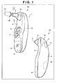
- the ear-type thermometer 1 has the design and weight which allow easy operation by one hand.
- the ear-type thermometer 1 is divided into a main body base 2 and a main body cover 4 which are made by injection molding with a particular resin material, and is structured such that a mounting board to be discussed later can be fixed in the interior.
- the main body base 2 and the main body cover 4 are formed from resin materials stained in different colors.
- the main body cover 4 is made from a semi-transparent resin, and is structured to allow viewing of blinking of two, internally placed light emitting LED elements 13 from the outside.
- so-called engineering plastic including polyethylene, polypropylene, polyolefins such as ethylene-vinyl acetate polymer, and polyesters including polyethylene terephthalate and polybutylene terephthalate, can be thought of.
- a probe cover 10 shown in dash-dotted line and has a shape identical to a part of the probe 3, is removably attached to the probe 3.
- This probe cover 10 prevents ear wax and other foreign matters from entering through the opening and into the probe 3, and is designed to be washable in alcohol and water on a regular basis when removed in order to maintain good hygienic condition.
- This probe cover 10 is typically prepared from polyethylene or polypropylene, olefin-type resins that transmit infrared light, to a predetermined thickness of, for example, 0.1 to 0.005mm by vacuum molding. However, other types of resin materials can also be used.
- a button for a power switch 5 that can be pressed for operation is placed below the probe 3. Also, below this power switch 5 a liquid crystal display unit 7 is placed which displays measured temperature using 7 segments, and characters such as icons which indicate the measurement is starting. Placed below this liquid crystal display unit 7 is a button battery cover 9 which can be removed from and attached to the main body base 2 when replacing a button battery 8 shown in dotted line.
- Fig. 2 is an exploded view of the ear-type thermometer shown in Fig.1 .
- Fig. 2 is an exploded view of the ear-type thermometer shown in Fig.1 .
- structures which are already explained and their parts are assigned the same numbers.
- the measurement switch 6 is retained and fixed in place.
- the measurement switch 6 can be moved back and forth in relation to the main body cover 4, which enables pressing and operating of a mechanical contact switch 6a that includes a tact switch mounted on a main mounting surface 15a of a mounting board 15.
- the piezoelectric speaker 12 shown in dotted line is fixed in advance, and wires 30 to the speaker 12 extend from the main mounting surface 15a of the mounting board 15.
- the main body base 2 forms edges which are identical in shape to the edges of the main body cover 4, and has integrally molded depressions 2f at locations corresponding to the protrusions 4f, each having a groove into which the respective protrusion 4f fit. Further, the upper portion of the main body base 2 has an integrally molded hook 2k which locks into the hook catching part 4k.
- a screw hole 15c and a fixation hole 15h, for fixing the mounting board 15 onto the main body base 2 are respectively drilled at positions indicated in the figure.
- attachment studs 2b and 2h are integrally molded on the main body base 2 at positions that correspond to the screw hole 15c and the fixation hole 15h.
- the two attachment studs are configured such that the mounting board 15 can be fixed onto the main body base 2 by aligning the screw hole 15c and fixation hole 15 onto the studs and screwing a screw 39 into the attachment stud 2b.
- an opening 2a which is connected to the inner perimeter surface of the probe 3, is formed.
- the probe cover 10 is set onto the probe 3 in the direction indicated by an arrow such that it covers the probe. Subsequently, the probe cover can be fixed in place by placing the probe attachment tool 11 and turning it in a direction indicated by the two arrows.
- a step 2x which makes contact with the bottom surface of the flange 10f of the probe cover 10 (shown in dotted and dashed lines) at a location corresponding to the bottom of the probe 3, is integrally formed on the main body cover 2 and is concentric with the probe 3.
- inner sleeves 2y are integrally formed to surround the step 2x, with a gap 2w in between themselves and the step 2x and being concentric with the probe 3.
- protrusions 2t shown in dotted lines which lock into the locking grooves 11k positioned at the center of the locking protrusions 11d.
- the probe 3 is covered with the probe cover 10, and the probe cover attachment tool 11 is lowered onto the probe 3 by gripping it at the gripping portions 11c.
- the locking protusions 11d one is shown in dotted lines
- the locking grooves 11k at the center of locking protrusions 11d are locked onto the protrusions 2t, preventing probe 3 from being released.
- Fig. 5 is an external perspective view of the detection element housing 20 wherein a part of the housing 20 is removed for view into the interior.
- a thermistor 21 which is a temperature detection element that detects ambient temperature
- an infrared detection element 22 which detects infrared light emitted from the temperature measurement site within the aural cavity
- the thermistor 21 which is fixed in such a manner, has been tweaked during the production stage to be able to measure ambient temperature of the usage environment, which is an absolute temperature.
- the mounting member 23 is made from a material which is a good conductor such as aluminum, which allows transmittance of external temperature and fixes the thermistor 21 to make its mounting surface large. Lead wires of the thermistor 21 are connected to electrode leads 28 which are fixed in place on and insulated from the mounting member 23.
- the infrared detection element 22 which detects infrared radiation (IR) is not capable of detecting absolute temperature but can only detect relative temperature change. For this reason, body temperature is attained by adding the temperature detected by the infrared detection element to the temperature detected by the temperature detection element. Details of such detection operation is explained in, for example, Japanese Patent Laid-Open No. H11-123179 , and will be omitted here.
- IR infrared radiation
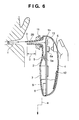
- Fig. 6 is a cross-section view in which the ear-type thermometer 1 is being inserted to aural cavity Y which is a measurement site.
- aural cavity Y which is a measurement site.
- the standby time for this measurement is the time required for display of an icon to be completed on the liquid crystal display unit 7.
- the probe 3 is to be inserted into the aural cavity Y as illustrated. When doing so, over-insertion into the aural cavity is prevented by a distance Y between the probe cover attachment tool 11 and the tip of the probe.
- Fig. 7 shows cross-sections depicting examples of a probe cover detection switch 60 which detects presence and absence of the probe cover 10.
- Fig.7 (7A) shows usage of a mechanical contact switch operates by making contact with the inner perimeter surface 10k of the probe cover 10 as the probe cover detection switch 60.
- Fig.7 (7B) shows use of an electric contact switch as the probe cover detection switch 60 placed on the inner side surface 34 of the probe 3 which operates by making contact with a conductive layer 66 laid on the inner perimeter surface 10k of the probe cover.
- Fig.7 (7A) by inserting the detection element housing 20 into the probe 3 such that the opening 31 gets blocked, the window member 26 of the detection element housing 20 is placed towards the top as shown in the figure, and the back surface of the mounting member 23 locks with the locking part 33 and fixes the housing 20 in place.
- the opening 31 of the probe 3 is formed at the top portion of a chamfered surface 32c at the end face 32 of the probe 3 as shown in the figure, and is integrally molded in the shape of a circle with a diameter of approximately 3 to 4 mm.
- the detection element housing 20 connected with wires 30 to the electrode leads 28 and 29 and the back side of the mounting board 23 is moved upwards using a tool not shown in the figure, the edges of the container member 25 makes contact with the slanted surfaces of the locking parts 33. If the housing 20 is moved further upward, the outer perimeter surface 25a of the container member 25 is guided by the top of the locking parts 33, and the sleeve 23a of the mounting member 23 (refer to Fig. 5 ) makes contact with the slanted surface. If the housing 20 is moved even further upwards, the edge of the sleeve 23a is pushed into the slanted surface of the locking parts, and elastically deforms the probe 3 in the radial direction.
- the surface of the window member 26 of the detection element housing 20 makes contact with the end face 32 such that it blocks the opening 31 of the probe 3 as shown in Fig. 7(7A) . Further, when using an O-ring (gasket), the portion protruding out of the groove is elastically deformed, allowing maintenance of a liquid-tight state.
- a hole 34x is drilled, and an actuator member 61 is placed which protrudes out of this hole in a radial direction.
- This actuator member 61 is placed such that it protrudes to the outside by the action of a compressed coil spring 62 which is inserted in between the actuator member 61 and a tact switch, a mechanical contact switch acting as the probe cover detection switch 60.
- a depression 11w is provided on the probe cover attachment tool 11 in order to accommodate the tip of the actuator member 61 at a protruded position when there is no probe cover 10.
- the light guiding tube 99 comprising a gold gilt cover reflective surface 70 is placed between the opening of the probe 3 and the hole 24 of the detection element housing 20. Further, an optical switch which detects the reflective layer 67 laid on the flange portion 10f of the probe cover 10 using reflected light, is placed on the mounting board 15 as a probe cover detection switch 60.
- the probe cover 10 when the probe cover 10 is set as shown in the figure and light from a light emitting element is reflected off the reflective layer 67 which is detected by a light receiving element, it is possible to detect that a probe cover is present. When there is no probe cover 10, no reflection of light occurs, and absence of probe cover is detected.
- Fig. 8 is a block diagram of the ear-type thermometer 1. Parts that are already explained will be assigned the same numbers as before and their explanations will be omitted.
- the infrared detection element 22 which detects infrared radiation IR is connected via the wires 30 to an amplifier 54 mounted on the mounting board 15.
- the first and second temperature conversion coefficients are calculated by the temperature calibration with the probe cover on and probe cover off, respectively, and these temperature conversion coefficients are calculated by the temperature calibration which calculates correlation coefficient between the detected body temperature signals based on detection results of the two detection elements and actual body temperature signals based on actual body temperature, and these temperature conversion coefficients are used for measuring correct body temperature by correction which perform temperature conversion by the temperature calibration.
- control unit 50 is connected to the LED element 13, the liquid crystal display unit 7 having a standby and temperature displaying parts, the speaker 12 which a warning unit, the power switch 5, and the measurement switch 6. Further, it is structured to be supplied with electric power from the power supply 8 which is the button battery. Further, the liquid crystal display unit 7 has a measurement standby/temperature display portion 7a and a probe cover usage count display portion 7b.
- Fig. 9 is a flow chart which explains operation of a main routine program.
- turning on of the power switch 5 is waited for to be turned on at step S1.
- the process moves to step S2 and the main routine is started, in which initialization processing such as reading out cover usage count from the storage unit and displaying the usage count on the display portion 7b.
- initialization processing such as reading out cover usage count from the storage unit and displaying the usage count on the display portion 7b.
- step S3 in order to indicate that the process is currently at a standby status prior to measurement, for example, an icon or a character is displayed gradually on the display portion 7a, starting from a small part, over a period of time that is required to complete the icon or character during which the standby status continues.
- measurement of ambient temperature by the thermistor 21 is performed.
- step S4 the measurement switch 6 is waited for to be turned on.
- the process advances to step S5 and detects electronic temperature signals from each of the detector elements 22.
- step S6 it is checked whether the probe cover detection switch 60 is turned on or not.
- the probe cover detection switch 60 is determined to be in a turned-on state at step S6, it is determined that the probe cover 10 is properly attached, and the process advances to step S7 and reads the first temperature conversion coefficient.
- step S9 obtains a body temperature by temperature conversion based on the first temperature conversion coefficient which was read at step S7.
- step S10 display of body temperature on the display portion 7a is performed.
- step S11 a notice of completion of body temperature is performed, and the processing finishes.
- Fig. 10 is a block diagram of the ear-type thermometer 1 according to a different embodiment. Parts that are already explained will be assigned the same numbers as before and their explanations will be omitted.
- the thermistor 21 installed in the detection element housing 20 shown in dashed lines is connected to the amplifier 53 mounted on the mounting board 15 via the wires 30.
- the infrared detection element 22 which detects infrared light IR is connected to the amplifier 54 mounted on the mounting board 15 via the wires 30.
- FIG. 11A is a flow chart explaining operation of a battery insertion program.
- the battery insertion program is started and a new button battery 8 is inserted after an old button battery 8 has run out, reset is released at step S1 and the process advances to step S2 in which initialization processing such as initial configuration of ports and clearance of the RAM (random access memory) are carried out.
- initialization processing such as initial configuration of ports and clearance of the RAM (random access memory) are carried out.
- step S3 erase of "ON code” of the RAM is performed, and the display portion of the liquid crystal display unit 7 is turned off at step S4.
- This "ON code” is a code used to discriminate whether power supply operation is a power ON operation or a power OFF operation by referring to it after the power supply operation.
- the operation is determined to be an OFF operation.
- the operation is determined to be an OFF operation.
- Fig. 11 shows a flow chart which explains operation of the interrupt processing program.
- the interrupt processing program starts.
- the process advances to step S8 and it is checked whether an "ON code" is written into the RAM.
- step S9 When it is checked there is no "ON code” written into the RAM at step S8, the process advances to step S9 and an "ON code” is written, and then the process advances to step S10 and jumps to a main routine program that will be discussed later.
- step S8 when it is checked at step S8 that an "ON code” is written, the process advances to step S11 and erases the "ON code", and then further advances to step S12 at which point the process jumps to the main routine program.
- Fig. 12 is a flow chart explaining operation of the main routine program.
- the main routine starts.
- the cover usage count ct is read from the storage unit, and the process advances to step S21 in which display indicating that the thermometer is in a measurement standby status using, for example, an icon, is performed on the liquid crystal device.
- step S22 pressing of the measurement switch 6 is waited for.
- step S23 detects electric temperature signals from each of the detection elements 21 and 22 which are thermopiles.
- step S24 it is checked whether the probe cover detection switch 60 is in an ON status, and determines that the probe cover 10 is properly attached when the detection switch is in the ON status. Then the process advances to step S25, and a temperature conversion coefficient is read out from the storage unit.
- step S26 a body temperature which is measured by temperature conversion based on the read-in temperature conversion coefficient is obtained. Subsequently, at step S27, 1 is added to the probe cover usage count ct stored in the RAM and is stored back in the RAM.
- step S29 the body temperature obtained from step S26 is displayed, and at step S29 an alert notifying completion of temperature detection is performed with the speaker 12, and pressing of the measurement switch is awaited for the subsequent round of measurement.
- the process can be forced to stop, and a message instructing replacement can be displayed on the liquid crystal display unit and usage thereafter can be prohibited (step S32)
- step S24 if it is determined that the probe cover detection switch 60 is turned off, it is determined that the probe cover 10 is removed and clears the probe cover usage count ct stored in the RAM to zero. Then the process advances to step S34 and displays an instruction to attach the probe cover 10, and then awaits pressing of the measurement switch.
Applications Claiming Priority (2)
| Application Number | Priority Date | Filing Date | Title |
|---|---|---|---|
| JP2007080124A JP5053674B2 (ja) | 2007-03-26 | 2007-03-26 | 耳式体温計 |
| PCT/JP2008/054581 WO2008117670A1 (ja) | 2007-03-26 | 2008-03-13 | 耳式体温計及びこれの制御方法 |
Publications (2)
| Publication Number | Publication Date |
|---|---|
| EP2130488A1 true EP2130488A1 (de) | 2009-12-09 |
| EP2130488A4 EP2130488A4 (de) | 2013-12-11 |
Family
ID=39788406
Family Applications (1)
| Application Number | Title | Priority Date | Filing Date |
|---|---|---|---|
| EP08738652.0A Withdrawn EP2130488A4 (de) | 2007-03-26 | 2008-03-13 | Klinisches ohrthermometer und steuerungsverfahren dafür |
Country Status (6)
| Country | Link |
|---|---|
| US (1) | US8126672B2 (de) |
| EP (1) | EP2130488A4 (de) |
| JP (1) | JP5053674B2 (de) |
| CN (1) | CN101646383B (de) |
| TW (1) | TW200843693A (de) |
| WO (1) | WO2008117670A1 (de) |
Cited By (2)
| Publication number | Priority date | Publication date | Assignee | Title |
|---|---|---|---|---|
| CN102335015A (zh) * | 2010-07-14 | 2012-02-01 | 泰尔茂株式会社 | 女性体温计 |
| EP2690358A1 (de) * | 2011-03-24 | 2014-01-29 | Olympus Corporation | Leuchtsystem |
Families Citing this family (27)
| Publication number | Priority date | Publication date | Assignee | Title |
|---|---|---|---|---|
| US8308355B2 (en) * | 2008-07-29 | 2012-11-13 | Welch Allyn, Inc. | Cycle counting |
| CN102282448B (zh) | 2008-12-29 | 2015-12-09 | Kaz欧洲有限公司 | 用于医疗温度计的具有匹配特征件的探针盖 |
| TWI495859B (zh) * | 2009-10-05 | 2015-08-11 | Kaz Europe Sa | 用於耳溫計之多點附接技術 |
| US8374683B2 (en) * | 2009-12-30 | 2013-02-12 | Ray D. Stone | Medical instrument with probe, probe cover, and methods of using the same |
| JP2012070919A (ja) * | 2010-09-28 | 2012-04-12 | Terumo Corp | 耳式体温計 |
| JP2012249655A (ja) * | 2011-05-31 | 2012-12-20 | Sony Corp | 光プローブ、被覆部材、光プローブの測定方法及び光パワーメータ |
| US8996096B2 (en) | 2011-07-19 | 2015-03-31 | Welch Allyn, Inc. | Systems and methods for determining patient temperature |
| WO2013049474A1 (en) * | 2011-09-29 | 2013-04-04 | Covidien Lp | Electronic thermometer with image sensor and display |
| US8949065B2 (en) * | 2011-09-30 | 2015-02-03 | Covidien Lp | Capacitive sensor for thermometer probe |
| US8292500B1 (en) | 2011-09-30 | 2012-10-23 | Tyco Healthcare Group Lp | IR sensor for electronic thermometer |
| US8651736B2 (en) | 2012-02-03 | 2014-02-18 | Welch Allyn, Inc. | Probe cover container identification |
| WO2013159301A1 (zh) * | 2012-04-25 | 2013-10-31 | Zhao Zhigang | 一种红外体温计清洁提醒方法 |
| JP6051693B2 (ja) * | 2012-09-03 | 2016-12-27 | セイコーエプソン株式会社 | 超音波プローブ、電子機器及び超音波診断装置 |
| TWM453480U (zh) * | 2012-10-11 | 2013-05-21 | Avita Corp | 體溫量測裝置 |
| DE102012223691A1 (de) * | 2012-12-19 | 2014-06-26 | Heine Optotechnik Gmbh & Co Kg | Otoskop mit abwerfbarem Ohrtrichter |
| TWI635849B (zh) * | 2013-03-15 | 2018-09-21 | 巴貝多商特洛伊海倫有限公司 | 溫度計使用者介面 |
| CN103263254A (zh) * | 2013-05-07 | 2013-08-28 | 宫文峰 | 便捷式电子体温计 |
| CA2912816A1 (en) * | 2013-06-19 | 2014-12-24 | F. Hoffmann-La Roche Ag | Combination of ro5503781 and capecitabine for cancer therapy |
| US9587985B2 (en) | 2013-08-08 | 2017-03-07 | Sharp Kabushiki Kaisha | Optical transmission device, light guide plug, optical fiber plug, light reception device, and portable apparatus |
| CN103439003B (zh) * | 2013-09-03 | 2016-08-31 | 重庆大学 | 一种提高红外测温精度的方法 |
| EP3078951A1 (de) * | 2015-04-10 | 2016-10-12 | Silverlight AG | Einrichtung mit pir sensor |
| CN106225956A (zh) * | 2016-08-31 | 2016-12-14 | 芜湖天宇科技开发有限公司 | 温度传感器多路阻值检测台及其检测方法 |
| CN106343968A (zh) * | 2016-10-11 | 2017-01-25 | 南阳市第二人民医院 | 一种电子耳温计 |
| CN106303091A (zh) * | 2016-10-19 | 2017-01-04 | 广东小天才科技有限公司 | 移动终端扬声器状态切换的方法及装置 |
| DE102018008622B4 (de) * | 2018-10-31 | 2020-10-01 | Sartorius Stedim Biotech Gmbh | Bioprozessbehälter mit optischer Messvorrichtung |
| CN112629663A (zh) * | 2019-09-20 | 2021-04-09 | 卡西欧计算机株式会社 | 外罩结构、检测装置以及检测装置的制造方法 |
| CN112674728B (zh) * | 2020-12-22 | 2023-07-04 | 河南国立微智能研究院有限公司 | 一种蓝牙无线体温监测装置 |
Citations (7)
| Publication number | Priority date | Publication date | Assignee | Title |
|---|---|---|---|---|
| WO1995000067A1 (en) * | 1993-06-18 | 1995-01-05 | Infra-Temp, Inc. | Electronic thermometer probe cover |
| DE19543096A1 (de) * | 1995-11-18 | 1997-05-22 | Braun Ag | Infrarot-Strahlungsthermometer |
| WO1997019331A1 (de) * | 1995-11-18 | 1997-05-29 | Braun Aktiengesellschaft | Verfahren zur auswertung des signales eines infrarot-thermometers sowie infrarot-thermometer |
| EP0997718A2 (de) * | 1998-10-28 | 2000-05-03 | Omron Corporation | Elektronisches Thermometer |
| JP2000217788A (ja) * | 1999-02-01 | 2000-08-08 | Matsushita Electric Ind Co Ltd | 放射体温計 |
| US6386757B1 (en) * | 1997-07-16 | 2002-05-14 | Terumo Kabushiki Kaisha | Ear type clinical thermometer |
| EP1262753A1 (de) * | 2001-06-01 | 2002-12-04 | Omron Corporation | Klinisches Infrarotthermometer |
Family Cites Families (8)
| Publication number | Priority date | Publication date | Assignee | Title |
|---|---|---|---|---|
| US5018872A (en) | 1988-11-01 | 1991-05-28 | Diatek, Inc. | Probe assembly for infrared thermometer |
| JPH11104086A (ja) * | 1997-09-30 | 1999-04-20 | Minolta Co Ltd | 体温計 |
| JP3615372B2 (ja) * | 1997-10-21 | 2005-02-02 | テルモ株式会社 | 赤外線体温計 |
| CN1297343A (zh) * | 1998-05-06 | 2001-05-30 | 松下电器产业株式会社 | 耳式妇女体温计 |
| JP3514138B2 (ja) * | 1998-09-29 | 2004-03-31 | テルモ株式会社 | プローブカバー取り外し機構および耳式体温計 |
| JP2001349787A (ja) * | 2000-06-06 | 2001-12-21 | Seiko Epson Corp | 赤外線検出素子および測温計 |
| US7036978B2 (en) | 2000-06-13 | 2006-05-02 | Omron Corporation | Pyrometer |
| KR100571811B1 (ko) * | 2003-05-09 | 2006-04-17 | 삼성전자주식회사 | 귀속형 생체 신호 측정 장치 |
-
2007
- 2007-03-26 JP JP2007080124A patent/JP5053674B2/ja not_active Expired - Fee Related
-
2008
- 2008-03-13 EP EP08738652.0A patent/EP2130488A4/de not_active Withdrawn
- 2008-03-13 CN CN2008800100820A patent/CN101646383B/zh not_active Expired - Fee Related
- 2008-03-13 WO PCT/JP2008/054581 patent/WO2008117670A1/ja active Application Filing
- 2008-03-20 TW TW097109746A patent/TW200843693A/zh unknown
-
2009
- 2009-09-25 US US12/567,354 patent/US8126672B2/en not_active Expired - Fee Related
Patent Citations (7)
| Publication number | Priority date | Publication date | Assignee | Title |
|---|---|---|---|---|
| WO1995000067A1 (en) * | 1993-06-18 | 1995-01-05 | Infra-Temp, Inc. | Electronic thermometer probe cover |
| DE19543096A1 (de) * | 1995-11-18 | 1997-05-22 | Braun Ag | Infrarot-Strahlungsthermometer |
| WO1997019331A1 (de) * | 1995-11-18 | 1997-05-29 | Braun Aktiengesellschaft | Verfahren zur auswertung des signales eines infrarot-thermometers sowie infrarot-thermometer |
| US6386757B1 (en) * | 1997-07-16 | 2002-05-14 | Terumo Kabushiki Kaisha | Ear type clinical thermometer |
| EP0997718A2 (de) * | 1998-10-28 | 2000-05-03 | Omron Corporation | Elektronisches Thermometer |
| JP2000217788A (ja) * | 1999-02-01 | 2000-08-08 | Matsushita Electric Ind Co Ltd | 放射体温計 |
| EP1262753A1 (de) * | 2001-06-01 | 2002-12-04 | Omron Corporation | Klinisches Infrarotthermometer |
Non-Patent Citations (1)
| Title |
|---|
| See also references of WO2008117670A1 * |
Cited By (5)
| Publication number | Priority date | Publication date | Assignee | Title |
|---|---|---|---|---|
| CN102335015A (zh) * | 2010-07-14 | 2012-02-01 | 泰尔茂株式会社 | 女性体温计 |
| EP2690358A1 (de) * | 2011-03-24 | 2014-01-29 | Olympus Corporation | Leuchtsystem |
| EP2690358A4 (de) * | 2011-03-24 | 2014-09-17 | Olympus Corp | Leuchtsystem |
| US9261261B2 (en) | 2011-03-24 | 2016-02-16 | Olympus Corporation | Illumination system |
| US10041655B2 (en) | 2011-03-24 | 2018-08-07 | Olympus Corporation | Illumination system |
Also Published As
| Publication number | Publication date |
|---|---|
| US20100017163A1 (en) | 2010-01-21 |
| TW200843693A (en) | 2008-11-16 |
| US8126672B2 (en) | 2012-02-28 |
| CN101646383B (zh) | 2011-09-28 |
| JP2008237396A (ja) | 2008-10-09 |
| JP5053674B2 (ja) | 2012-10-17 |
| EP2130488A4 (de) | 2013-12-11 |
| WO2008117670A1 (ja) | 2008-10-02 |
| CN101646383A (zh) | 2010-02-10 |
Similar Documents
| Publication | Publication Date | Title |
|---|---|---|
| EP2130488A1 (de) | Klinisches ohrthermometer und steuerungsverfahren dafür | |
| TWI383777B (zh) | 耳式體溫計 | |
| JP3646652B2 (ja) | 赤外線温度計 | |
| US9404813B2 (en) | Systems and methods for determining patient temperature | |
| AU2010239577B2 (en) | Calibrated assembly for IR thermometer apparatus | |
| US6612735B2 (en) | Infrared ray clinical thermometer | |
| JP2004533618A (ja) | 温度プローブアダプタ | |
| JPH0320630A (ja) | 槽の操作状態を表示する装置 | |
| JP2011062370A (ja) | 耳式体温計 | |
| JP2008241364A (ja) | 耳式体温計 | |
| JP3770265B2 (ja) | 赤外線温度計 | |
| JP2008237397A (ja) | 耳式体温計及びこれの制御方法 | |
| CN211927106U (zh) | 一种多功能额温枪 | |
| JP3160909U (ja) | 耳式体温計 | |
| US20080075144A1 (en) | Display assembly of a digital thermometer | |
| JP3160911U (ja) | 耳式体温計 | |
| JP2009229130A (ja) | 電子体温計 | |
| JP2011062368A (ja) | 耳式体温計 | |
| CN105030211B (zh) | 快速测温仪及其测温控制方法 | |
| CN219870044U (zh) | 一种温度检测装置 | |
| CN205458618U (zh) | 体温检测装置 | |
| JP3759784B2 (ja) | 生体情報収集装置 | |
| KR20090036975A (ko) | 온도측정장치 | |
| JP2011062369A (ja) | 耳式体温計 | |
| JPH11104086A (ja) | 体温計 |
Legal Events
| Date | Code | Title | Description |
|---|---|---|---|
| PUAI | Public reference made under article 153(3) epc to a published international application that has entered the european phase |
Free format text: ORIGINAL CODE: 0009012 |
|
| 17P | Request for examination filed |
Effective date: 20091015 |
|
| AK | Designated contracting states |
Kind code of ref document: A1 Designated state(s): AT BE BG CH CY CZ DE DK EE ES FI FR GB GR HR HU IE IS IT LI LT LU LV MC MT NL NO PL PT RO SE SI SK TR |
|
| DAX | Request for extension of the european patent (deleted) | ||
| A4 | Supplementary search report drawn up and despatched |
Effective date: 20131111 |
|
| RIC1 | Information provided on ipc code assigned before grant |
Ipc: G01J 5/00 20060101ALI20131105BHEP Ipc: G01J 5/04 20060101ALI20131105BHEP Ipc: G01J 5/02 20060101ALI20131105BHEP Ipc: G01J 5/08 20060101ALI20131105BHEP Ipc: A61B 5/01 20060101AFI20131105BHEP Ipc: G01J 5/06 20060101ALI20131105BHEP |
|
| STAA | Information on the status of an ep patent application or granted ep patent |
Free format text: STATUS: THE APPLICATION IS DEEMED TO BE WITHDRAWN |
|
| 18D | Application deemed to be withdrawn |
Effective date: 20140611 |