EP2130013B1 - Automatic selection of colorants and flakes for matching coating color and appearance - Google Patents
Automatic selection of colorants and flakes for matching coating color and appearance Download PDFInfo
- Publication number
- EP2130013B1 EP2130013B1 EP08725875.2A EP08725875A EP2130013B1 EP 2130013 B1 EP2130013 B1 EP 2130013B1 EP 08725875 A EP08725875 A EP 08725875A EP 2130013 B1 EP2130013 B1 EP 2130013B1
- Authority
- EP
- European Patent Office
- Prior art keywords
- color
- appearance
- data
- flake
- target
- Prior art date
- Legal status (The legal status is an assumption and is not a legal conclusion. Google has not performed a legal analysis and makes no representation as to the accuracy of the status listed.)
- Active
Links
Images


Classifications
-
- G—PHYSICS
- G01—MEASURING; TESTING
- G01J—MEASUREMENT OF INTENSITY, VELOCITY, SPECTRAL CONTENT, POLARISATION, PHASE OR PULSE CHARACTERISTICS OF INFRARED, VISIBLE OR ULTRAVIOLET LIGHT; COLORIMETRY; RADIATION PYROMETRY
- G01J3/00—Spectrometry; Spectrophotometry; Monochromators; Measuring colours
- G01J3/46—Measurement of colour; Colour measuring devices, e.g. colorimeters
- G01J3/50—Measurement of colour; Colour measuring devices, e.g. colorimeters using electric radiation detectors
-
- B—PERFORMING OPERATIONS; TRANSPORTING
- B44—DECORATIVE ARTS
- B44D—PAINTING OR ARTISTIC DRAWING, NOT OTHERWISE PROVIDED FOR; PRESERVING PAINTINGS; SURFACE TREATMENT TO OBTAIN SPECIAL ARTISTIC SURFACE EFFECTS OR FINISHES
- B44D3/00—Accessories or implements for use in connection with painting or artistic drawing, not otherwise provided for; Methods or devices for colour determination, selection, or synthesis, e.g. use of colour tables
- B44D3/003—Methods or devices for colour determination, selection or synthesis, e.g. use of colour tables
-
- G—PHYSICS
- G01—MEASURING; TESTING
- G01J—MEASUREMENT OF INTENSITY, VELOCITY, SPECTRAL CONTENT, POLARISATION, PHASE OR PULSE CHARACTERISTICS OF INFRARED, VISIBLE OR ULTRAVIOLET LIGHT; COLORIMETRY; RADIATION PYROMETRY
- G01J3/00—Spectrometry; Spectrophotometry; Monochromators; Measuring colours
- G01J3/46—Measurement of colour; Colour measuring devices, e.g. colorimeters
- G01J3/463—Colour matching
-
- G—PHYSICS
- G01—MEASURING; TESTING
- G01J—MEASUREMENT OF INTENSITY, VELOCITY, SPECTRAL CONTENT, POLARISATION, PHASE OR PULSE CHARACTERISTICS OF INFRARED, VISIBLE OR ULTRAVIOLET LIGHT; COLORIMETRY; RADIATION PYROMETRY
- G01J3/00—Spectrometry; Spectrophotometry; Monochromators; Measuring colours
- G01J3/46—Measurement of colour; Colour measuring devices, e.g. colorimeters
- G01J3/50—Measurement of colour; Colour measuring devices, e.g. colorimeters using electric radiation detectors
- G01J3/504—Goniometric colour measurements, for example measurements of metallic or flake based paints
-
- B—PERFORMING OPERATIONS; TRANSPORTING
- B05—SPRAYING OR ATOMISING IN GENERAL; APPLYING FLUENT MATERIALS TO SURFACES, IN GENERAL
- B05D—PROCESSES FOR APPLYING FLUENT MATERIALS TO SURFACES, IN GENERAL
- B05D5/00—Processes for applying liquids or other fluent materials to surfaces to obtain special surface effects, finishes or structures
- B05D5/06—Processes for applying liquids or other fluent materials to surfaces to obtain special surface effects, finishes or structures to obtain multicolour or other optical effects
Definitions
- the present invention is directed to a method and a system for producing one or more matching formulas to match color and appearance of a target coating containing flakes.
- effect pigments such as light absorbing pigment, light scattering pigments, light interference pigments, and light reflecting pigments
- Flakes such as metallic flakes, for example aluminum flakes, are examples of such effect pigments and are especially favored for the protection and decoration of automobile bodies, such as for example by reason of their imparting a differential light reflection effect, usually referred, to as "flop", as well as flake appearance effects, which include flake size distribution and the sparkle imparted by the flake as well as the enhancement of depth perception in the coating.
- the flake containing coatings usually also contain other pigments or colorants, generally of a light absorbing rather than a light scattering type. These light absorbing pigments interact with effect pigments such as flakes to change the appearance effect of the coating.
- visual coating appearance includes texture, sparkle, glitter or other visual effects of a coating. The visual appearance can vary when viewed from varying viewing angles, with varying illumination angles, or with varying illumination intensities.
- test coatings are then prepared based on the preliminary matching formulas and sprayed on test panels, which are then visually compared to the target coating. If the appearance such as flop and/or sparkle match are deemed unsatisfactory, the shader adjusts the type and/or changes the amount of the flakes entered into the algorithm to get new color/flop matching formulas and the whole cycle is repeated until an adequate match is achieved in both color and appearance at all angles of illumination and view. This traditional approach, however, requires repeated spraying and visually comparing test panels with the target coating.
- US 2001/036309 A1 describes a computer color-matching apparatus and paint color-matching method using the apparatus.
- pigment refers to a colorant or colorants that produce color or colors.
- a pigment can be from natural and synthetic sources and made of organic or inorganic constituents.
- a pigment also includes metallic particles or flakes with specific or mixed shapes and dimensions.
- a pigment is usually not soluble in a coating composition.
- effect pigment refers to pigments that produce special effects in a coating.
- effect pigments include, but not limited to, light scattering pigments, light interference pigments, and light reflecting pigments. Flakes, such as metallic flakes, for example aluminum flakes, are examples of such effect pigments.
- Gonioapparent flakes refer to flakes which change color or appearance, or a combination thereof, with change in illumination angle or viewing angle.
- Metallic flakes, such as aluminum flakes are examples of gonioapparent flakes.
- Dye means a colorant or colorants that produce color or colors.
- Dye is usually soluble in a coating composition.
- “Appearance” used herein refers to (1) the aspect of visual experience by which a coating is viewed or recognized; and (2) perception in which the spectral and geometric aspects of a coating is integrated with its illuminating and viewing environment.
- appearance includes texture, sparkle, or other visual effects of a coating, especially when viewed from varying viewing angles and/or with varying illumination angles.
- the term "database” refers to a collection of related information that can be searched and retrieved.
- the database can be a searchable electronic numerical, alphanumerical or textual document; a searchable PDF document; a Microsoft Excel® spreadsheet; a Microsoft Access® database (both supplied by Microsoft Corporation of Redmond, Washington); an Oracle® database (supplied by Oracle Corporation of Redwood Shores, California); or a Linux database, each registered under their respective trademarks.
- the database can be a set of electronic documents, photographs, images, diagrams, or drawings, residing in a computer readable storage media that can be searched and retrieved.
- a database can be a single database or a set of related databases or a group of unrelated databases. "Related database” means that there is at least one common information element in the related databases that can be used to relate such databases.
- One example of the related databases can be Oracle® relational databases.
- vehicle refers to an automobile such as car, van, mini van, bus, SUV (sports utility vehicle); truck; semi truck; tractor; motorcycle; trailer; ATV (all terrain vehicle); pickup truck; heavy duty mover, such as, bulldozer, mobile crane and earth mover; airplanes; boats; ships; and other modes of transport that are coated with coating compositions.
- SUV sport utility vehicle
- SUV sport utility vehicle
- truck semi truck
- tractor tractor
- motorcycle trailer
- ATV all terrain vehicle
- pickup truck heavy duty mover, such as, bulldozer, mobile crane and earth mover
- airplanes boats; ships; and other modes of transport that are coated with coating compositions.
- a computing device used herein refers to a desktop computer, a laptop computer, a pocket PC, a personal digital assistant (PDA), a handheld electronic processing device, a smart phone that combines the functionality of a PDA and a mobile phone, or any other electronic devices that can process information automatically.
- a computing device may have a wired or wireless connection to a database or to another computing device.
- a computing device may be a client computer that communicates with a host computer in a multi-computer client-host system connected via a wired or wireless network including intranet and internet.
- a computing device can also be configured to be coupled with a data input or output device via wired or wireless connections.
- a laptop computer can be operatively configured to receive color data and images through a wireless connection.
- a computing device may further be a subunit of another device. Examples of such a subunit can be a processing chip in an imaging device, a spectrophotometer, or a goniospectrophotometer.
- a computing device may be connected to a display device, such as a monitor screen. However, the display device is not necessary.
- a "portable computing device" includes a laptop computer, a pocket PC, a personal digital assistant (PDA), a handheld electronic processing device, a mobile phone, a smart phone that combines the functionality of a PDA and a mobile phone, a tablet computer, or any other stand alone or subunit devices that can process information and data and can be carried by a person.
- PDA personal digital assistant
- Wired connections include hardware couplings, splitters, connectors, cables or wires.
- Wireless connections and devices include, but not limited to, Wi-Fi device, Bluetooth device, wide area network (WAN) wireless device, Wi-Max device, local area network (LAN) device, 3G broadband device, infrared communication device, optical data transfer device, radio transmitter and optionally receiver, wireless phone, wireless phone adaptor card, or any other devices that can transmit signals in a wide range of electromagnetic wavelengths including radio frequency, microwave frequency, visible or invisible wavelengths.
- An imaging device refers to a device that can capture images under a wide range of electromagnetic wavelengths including visible or invisible wavelengths. Examples of the imaging device include, but not limited to, a still film optical camera, a digital camera, an X-Ray camera, an infrared camera, an analog video camera, and a digital video camera.
- a digital imager or digital imaging device refers to an imaging device captures images in digital signals. Examples of the digital imager include, but not limited to, a digital still camera, a digital video camera, a digital scanner, and a charge coupled device (CCD) camera.
- An imaging device can capture images in black and white, gray scale, or various color levels. A digital imager is preferred in this invention. Images captured using a non-digital imaging device, such as a still photograph, can be converted into digital images using a digital scanner and can be also suitable for this invention.
- the imaging device can further comprise an illumination device.
- An illumination device for providing illuminations typically includes a light source, such as, the IT3900 with a tungsten-halogen lamp EKE supplied by Illumination Technologies Inc., East Syracuse, New York and a fiber optic bundle A08025.60 supplied by Schott Fostec Inc., Auburn, New York that is capable of producing beams of illumination in the visible light range of from 400 nanometers to 700 nanometers at set intensities.
- the system which is preferably portable, is preferably provided with an enclosed extension to house the light source.
- illumination devices such as the MHF-C50LR light source with an LM-50 lamp and a fiber optic bundle connected to a MML4-45D micro machine lens system, supplied by Moritex USA Inc., San Jose, California to pipe-in the illumination beams from the light source, are also suitable.
- the means for selecting an effective illumination intensity can be any conventional means, such as a voltage regulator that can change the current to the filament of the light source.
- the illumination intensity can be controlled in accordance with a conventional software program run from a computer to achieve the preset intensities.
- the computer used here to control the illumination intensity can be the same aforementioned computing device for receiving the image or a separate computer. Any suitable computer can be used, such as, for example, Dell Precision M50 model supplied by Dell Computer Corp., Round Rock, Texas.
- the system may comprise additional means such as a collimating lens or an aperture, for collimating the one or more beams of light emanating from light source as determined necessary by those skilled in the art.
- the illumination device may further provide modulations of illumination angles.
- the illumination device can also be part of the imaging device.
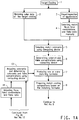
- Figure 1 outlines a typical traditional workflow for matching color and appearance of a target coating 1.
- color data of the target coating are obtained in the step 2.
- Color data can be obtained as reflectance data, L*,a*,b* or L,C,h values, or spectral data provided by a color measuring device such as a spectrophotometer.
- Color data can also be obtained by importing into the computing device from digital data files containing required color data.
- appearance data of the target coating is obtained by visual inspection (step 3 ) of the target coating and appearance match is done manually by one or more experienced shaders, based on their expertise to identify the presence or absence of any effect pigments such as flakes, wherein said target coating can be a previously coated substrate of an automotive body. If one or more effect pigments such as flakes are present in the target coating, the shaders manually select, in step 4, one or more flakes, flake combinations, or flake ratios from a set of known flakes that may potentially match appearance of the target coating.
- Color match can be done automatically based on color data using a computing device and well developed color matching algorithms operatively residing in the computing device.
- color matching algorithm is described in detail in aforementioned US 2006/0181707 A1 . Since the presence of flakes affects colorants selection, the color data and the selected flakes, flake combinations or flake ratios are entered into the color matching algorithm in step 5 to select match colorants. Concentrations of each of the colorants and flakes are determined in step 6 by the algorithm. One or more matching formulas are then produced in step 7 based on the concentrations of the colorants and the flakes. If necessary, concentrations of the colorants and the flakes are balanced to allow for the presence of non-colorant and non-flake components.
- non-colorant or non-flake components include, but not limited to, binder polymers, solvents, additives such as UV screeners, light stabilizers, rheology control agents, flow agents, adhesion promoters, catalysts, and other materials determined necessary for the coating by those who are skilled in the art. Some or all of the non-colorant or non-flake components can also be pre-balanced with all necessary materials determined by those who are skilled in the art.
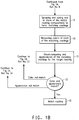
- Preliminary matching coating compositions are then prepared in step 8 based on the matching formulas and sprayed on test panels to form preliminary match coatings in step 9. The color of each of the preliminary match coatings is typically measured using an aforementioned color measuring device in step 10.
- step 11 The color and appearance of those preliminary match coatings are then visually compared to the target coating in step 11. If the color match is deemed not satisfactory ( 12 ), the shader adjusts colorants and new colorant and flake concentrations are computed in step 13. The color measurement data of the preliminary match coatings obtained in step 10 can be used to assist the adjustment of colorants. New matching formulas are then produced (step 7 ) and the whole cycle is repeated. If the appearance such as flop and/or sparkle match are deemed unsatisfactory, the shader adjusts the type and/or changes the amount of the flakes in step 14 and enters the new flake selection into the algorithm to calculate new colorants and flake concentrations in step 13.
- a set of new matching formulas are then produced and the steps of 7 through 12 are repeated until one or more match coatings having adequate match in both color and appearance ( 15 ) are obtained. It is acceptable in the industry that color and appearance may be achieved at all or some predetermined angles of illumination or view. This traditional approach, however, requires repeated spraying and visually comparing test panels with the target coating.
- An example is directed to a method for automatic selection of match flakes for producing one or more matching formulas for matching both color and appearance of a target coating containing flakes. This example improves the typical traditional workflow reducing the need for repeated spraying and visually comparing the test panels.
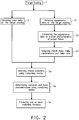
- Figure 2 outlines a first representative flow chart of this invention.
- Color data of the target coating can be obtained in step 2 in the same way as the aforementioned traditional process.
- appearance data can be obtained in step 21 using an appearance measurement device.
- the appearance data are then compared with stored appearance characteristics of known flakes in step 22 in a flake database.
- One or more known flakes, flake combinations or flake ratios are automatically selected in step 23 so that the appearance characteristics of the selected flakes, flake combinations or flake ratios match the appearance data.
- the selected flakes, flake combinations or flake ratios are then entered into the color matching algorithm to select match colorants in step 5a. Concentrations of each of the colorants and flakes are determined by the algorithm in step 6a.
- One or more matching formulas are then produced in step 7a based on the concentrations of the colorants and the flakes. If necessary, concentrations of the colorants and the flakes can be balanced to compensate for the presence of non-colorant and non-flake components.
- preliminary matching coating compositions can be prepared based on the matching formulas and test sprayed to form match coatings and compared according to steps 8 - 15 shown in Figure 1 . Steps 21 - 23 in Figure 2 ensure that accurate appearance data are obtained without the need for visual inspection by one or more experienced shaders based on their expertise. In addition, the appearance data are compared with stored appearance characteristics of known flakes in a flake database resulting in better appearance match. With this invention, fewer matching formulas are produced and fewer test sprays are needed resulting in improved productivity and shortened time needed for obtaining acceptable match coatings.
- the appearance data can be obtained by capturing one or more target images using an imaging device and subsequent measurement of the target images using a computing device.
- the target images can be still images or video images. Both still images and video images are suitable for this invention.
- the target images, either still or video images can be stored in digital formats for measurement of appearance characteristics at the same time or at a different time.
- the target images can also be captured and transmitted to a computing device for measurement of appearance without being stored permanently, such as real-time video images without being stored. In this invention, stored images are preferred.
- the appearance data can also be generated by an appearance measurement device and stored as non-image electronic files.
- non-image electronic files include, but not limited to, numerical, textual or alphanumerical data files correlating positions and appearance data at each of the positions.
- Image and non-image data files can be converted to each other according to well known methods. For example, an image can be measured using methods described below and stored into a separate non-image data file.
- appearance data of a target coating containing flakes can be obtained as described below.
- Illuminations at a fixed illumination angle and at varying illumination intensities are directed to the target coating.
- the fixed illumination angle can be at a perpendicular (0°), also known as normal (0°) angle to the surface of the target coating, or an angle within the range from -5° to +5° from the normal.
- Image capture is also at the normal angle.
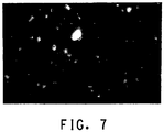
- Illumination intensity is in such a range that within the captured image, sparkles caused by the flakes are brighter than other target coating areas where no flakes are visible.
- the flakes in the target coating exhibit varying brightness or sparkles under varying illumination intensities.
- an illumination intensity setting is selected so that the brightest parts of the image are at or close to a maximum image intensity level while at the same time objects at lower image intensities are still visible in the image.
- the selected illumination intensity is referred to as an effective illumination intensity.
- a commonly used imaging device stores digital images with image intensity levels ranging from 0 to 255 wherein 0 represents the darkest and 255 represents brightest parts of an image. When such commonly used imaging device is used, the maximum image intensity level is 255. This range comes from the 8 bits data format used to represent the data of any one pixel in the digital image. When other data formats are used, image intensity levels may change. Those skilled in the art can select any workable data formats, image intensities and illumination intensities.
- At least one image of the target coating under the effective illumination intensity is captured using the aforementioned imaging device.
- An imaging device refers to a device that can capture images under a wide range of electromagnetic wavelengths including visible or invisible wavelengths.
- Preferred imaging device is a digital still camera, a digital video camera, a digital scanner, or a charge coupled device (CCD) camera.
- An imaging device can capture images in black and white, gray scale, or various color levels.
- the image captured by the imaging device can be stored in one of the commonly used digital image file formats, such as, but not limited to ".bmp” (Windows Bitmap), “.tif” or “.tiff” (Tagged Image File Format), ".jpg” or “.jpeg” (Joint Photographic Experts Group image file format), ".gif” (Graphics Interchange Format), or “.wmf” (Windows Metafile format).
- the images can also be captured in analog format and converted into digital format by methods well known to those skilled in the art.
- the images can also be analog or digital video images.
- the images can be entered into a computing device through a wired or wireless connection.
- An appearance feature is a characteristic or attribute that contributes to the visual appearance of a coating.
- An appearance feature can be identified and localized as a sparkle object, a flake or a flake-like object, a physical distance between two adjacent objects, a region where one or more objects reside, a region having multiple objects, or a combination thereof.
- a feature can also be a characteristic or attribute such as distribution of intensities, variation of intensities, or other statistical descriptions of the coating appearance.
- Appearance features can be quantitative or qualitative descriptions of the appearance of the coating. Quantitative descriptions, such as size, brightness, or other descriptions with numeric values are preferred.
- appearance features can comprise a set of bright features from bright areas of said image where the effect pigments such as metallic flakes exhibit highest brightness, a set of intermediate features from intermediate areas of the image where the effect pigments exhibit intermediate brightness, and a set of dark features from dark areas of the image where the target coating is essentially free of detectable said effect pigments.
- a threshold level used herein refers to an image intensity level where any pixels having the image intensity level equal or greater than the threshold level will be measured.
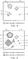
- a threshold level T1 of 225 can be set for bright areas meaning that pixels or regions of pixels of the image having image intensity equal or greater than 225 will be identified as bright features, such as objects 42 - 46 in the area 41 of Figure 4 or object 85 in Figure 8A .
- a second threshold level T2 can be set at 150 for intermediate brightness. Objects having image intensity equal or greater than 150 can be identified as intermediate features, such as objects 51 - 55 in Figure 5 or objects 86 and 87 in Figure 8B .
- a threshold level T3 of 100 can be set for dark features meaning that pixels or regions of pixels of the image having image intensity below 100 will be identified as dark features, such as area 64 in Figure 6 or area 88 in Figure 8C where essentially no flakes or flake-like objects are detectable. Some other objects, such as objects 62 and 63 in Figure 6 or object 89 in Figure 8C that have image intensities below the threshold level T2, but above T3 can be identified and considered when generating dark feature values.
- Individual feature values are generated for individual appearance features identified as described above.
- a number of feature values can be generated based on features identified. Examples of feature values include: (1) Total number of distinct and contiguous sparkle objects having image intensity equal or greater than a set first threshold level T1; (2) Average number of small sparkle objects measured in each of the images; (3) Average number of medium sparkle objects measured in each of the images; (4) Average number of large sparkle objects measured in each of the images; (5) Average number of extra large sparkle objects measured in each of the images; (6) Fractional area of each image having image intensities above the set first threshold level (Area T1); (7) The number of sparkle objects where the size of the sparkle object is expanded at a second Threshold Level T2, such as objects 51 and 52 in Figure 5 ; (8) Average number of new sparkle objects wherein a new sparkle object is a contiguous area that is distinct at the second Threshold Level T2, such as objects 53, 54 and 55 in Figure 5 ; (9) Fractional area of each image having image intensities greater than the second threshold level T2
- Appearance characteristics can be generated based on the individual feature values generated. Examples of such appearance characteristics include such ratios of Area Exp/Area T1 and Area New/Area T1. These ratios are related to physical properties of flakes in the coating and contribute to the appearance of the target coating. Other appearance characteristics may be generated as determined necessary by those skilled in the art.
- appearance data of a target coating containing flakes can be obtained with a process described in detail in US 6,952,265 , said process is briefly described below.
- one or more beams of illumination at a preset intensity is directed towards the target coating.
- the beams can be directed at a perpendicular (0°), also known as normal (0°) angle to the surface of target coating, or an angle within the range from -5° to +5° from the normal.
- one or more beams of illumination are directed sequentially at plurality of preset intensities, preferably at at least two, and more preferably at least three preset intensities.
- a reflection of the target coating is directed to an imaging device to capture a target image in color or preferably in gray scale, of the target coating.
- one or more reflections of the target coating are directed sequentially at plurality of other preset intensities to the imaging device.
- the target images captured can be transmitted to a computing device, such as a computer, or a portable computer.
- Appearance data of the target coating can be generated by the computing device by measuring appearance characteristics from the images.
- One measurement suitable for generating said appearance data is described in aforementioned US 6,952,265 with the following steps:
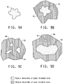
- step (a) when the target image at first of the preset intensities and at first of threshold levels is scanned, i.e., at the highest threshold level, only regions of pixels representing flakes having most prominent visible features would be located. The location and size, in accordance with the preset criteria of sizes, such a region is recorded as a new flake (91) shown in Figure 9A .
- step (c) when the same target image is scanned in step (c) at a lower threshold level, it is possible that new regions of pixels could become recognizable above the lower threshold level in the target image at the first of preset intensities.
- a previously located region recorded as new flake (91) may appear larger once its additional features (92) are located at the lower threshold level ( Figure 9B ).
- the foregoing coincident regions include single contiguous regions of pixels recognizable above the first threshold level that are enveloped within single regions of pixels recognizable above said lower threshold level. Under such a scenario the previously located and recorded size of the flake is discarded and the new larger size is recorded in its place.
- the foregoing coincident regions can also include plurality of regions of pixels recognizable above the first threshold level that are merged within regions of pixels recognizable above the lower threshold level.
- a cluster of small regions (94), which were previously located and recorded as new flakes of small size, when analyzed at a lower threshold level can be part of a larger flake (95) ( Figure 9C ). Under such a scenario, the previously located and recorded size of these small regions is discarded and a new larger region is located and recorded in their place.
- a large region (96) could be located adjacent to a small region (97), both of which would be located and recorded.
- the same combination when viewed at a lower threshold level can become part of a new larger region (98) ( Figure 9D ).
- the previously located and recorded sizes of these large (96) and small (97) regions are kept and the new larger region (98) is discarded, since the new larger region is likely to be a result of multiple flakes appearing as one merged flake, which should not, therefore, be counted as one large flake but should be counted as two distinct regions, namely the large region (96) and the small region (97).
- said measurement method By locating and recording the number of flakes from the target images at different thresholds and multiple illumination levels, said measurement method generates appearance data including a plurality of target features and corresponding target feature values that reflect sizes of the flakes in the target coating at pre-set illumination intensities.
- a target coating having flakes as effect pigments are specifically described, the above mentioned method is also suitable for coatings containing other effect pigments.
- one or more images of the target coating can be captured with a process comprising the steps of:
- one or more images of the target coating can also be captured with a fourth process comprising the steps of:
- one or more images of the target coating can be captured with a fifth process comprising the steps of:
- appearance data can be generated without capturing target images. It can be done by detecting the reflectance of the target coating and directly recording in a non-image data file such as a set binary data files, or other non-image data files that can record appearance information. Any aforementioned digital imaging devices can be configured directly or through a converter to generate non-image data file, such as a binary data file. An image recorded by an analog imaging device such as a photograph captured by a still film camera, can be converted into a digital image, or a non-image data file by, for example, a scanner.
- Appearance characteristics of a number of known flakes stored in a flake database can be generated by first preparing paint panels coated with individual benchmarking coatings described in aforementioned US 6,952,265 , wherein relevant sections from line 52, column 12 through line 49, column 13 of said US 6,952,265 are incorporated herein by reference, and then measuring appearance characteristics by one or more of the methods described above. It is understood that appearance characteristics of known flakes stored in the flake database need to be generated with the same as or compatible with the aforementioned imaging and measurement methods.
- the appearance data of the target coating can be compared to each individual appearance characteristic stored in the flake database. Differences between the appearance data and each individual appearance characteristics stored are herein referred to as "feature distances". A simple sum, a root mean square of sum, a weighted aggregated sum, or other calculated sum of feature distances can then be generated. It is well understood by those skilled in the art that different weighing factor(s) can be given to each feature, feature value or feature distance to produce optimized color and/or appearance match. Calculation considerations, weighing factors and algorithms are described in detail in aforementioned US 6,952,265 . Results of the comparisons are ranked based on selected sum of feature distances. The top ranked flake, flake combination or flake ratio can be automatically selected as the best match and then entered into well developed color matching algorithms to produce one or more matching formulas for matching both color and appearance of the target coating.
- Color data of the target coating can be obtained by measuring reflectances of the target coating using a color measurement device, such as a colorimeter, a spectrophotometer, or a goniospectrophotometer.
- a color measurement device such as a colorimeter, a spectrophotometer, or a goniospectrophotometer.
- Any suitable colorimeter or spectrophotometer such as Model SP64 manufactured by X-Rite, Grandville, Michigan can be used.
- Portable spectrophotometers are preferred as they can be readily positioned over coated substrate surfaces of various shapes and sizes. If desired one can measure the reflectances over several portions of the target coating to average out the reflectances of the target coating.
- Spectral reflectance data can be obtained using spectrophotometer.
- a light beam of known intensity can be directed towards the target coating and reflectance from the target coating is sequentially measured at at least one, preferably at two, even more preferably at three, aspecular angles at preset wavelengths.
- a light beam of known intensity can be sequentially directed at at least one, preferably at two, even more preferably at three, incident angles towards the target coating and reflectance from the target coating is then measured at preset wavelengths with a single detecting device so as to provide measurements at different aspecular angles, depending on the angle of illumination.
- a goniospectrophotometer is a spectrophotometer having the capability of measuring with a variety of illuminating and viewing angles using bidirectional geometry.
- a goniospectrophotometer is also known as multi-angle spectrophotometer. Any suitable Goniospectrophotometers, such as Model MA68II from X-Rite, Grandville, Michigan, or the ones provided by Murakami Color Research Laboratory, Tokyo, Japan, or by IsoColor Inc., Carlstadt, New Jersey, USA, can be used. Gonioapparent colors should be measured at multiple angles, preferably 3 to 5. For solid colors, a single aspecular angle is sufficient, typically 45 degrees.
- a common practice for solid colors is to illuminate at a single angle and measure the diffuse reflectance using an integrating sphere, capturing the light reflected at all angles from the target coating. The reverse method of illuminating diffusely and measuring at a single angle yields equivalent results. Diffuse reflectance is preferred when the target coating has a textured surface.
- spectral curve A plot of the percent reflectance as a function of wavelength is referred to as a "spectral curve" or spectral reflectance data.
- spectral curve For a solid color (non-flake or non-gonioapparent color, such as that lacking metallic flakes), only one spectral curve is typically sufficient to measure solid color properties.
- Other common geometries of measurement are diffuse illumination with 0° or 8° viewing or the reverse. If a target coating having flakes, i.e., gonioapparent color was being matched, reflectance measurements at additional angles would be necessary.
- ASTM E-2194 recommends three angles, 15°, 45°, and 110° as measured away from the specular reflection.
- DIN 6175-2 recommends up to five angles, all within this same range of angles.
- the X-Rite MA68II can provide measurements at 15°, 25°, 45°, 75°, and 110°.
- the measurement data or spectral reflectance data can be converted into L*,a*,b* or L,C,h values as described in detail in aforementioned US 2006/0181707 A1 .
- Color data may include spectral characteristics such as chroma, hue, lightness, darkness, and the like. Color data may further include a color code of a vehicle, a vehicle identification number (VIN) of a vehicle, a part of the VIN, or a combination thereof.
- VIN vehicle identification number
- Color data of the target coating obtained as described above can be compared with color characteristics stored in a color database to select one or more colorant combinations of known colorants, wherein said colorant combinations have color characteristics matching said color data via methods well known to those who are skilled in the art.
- One example of such well known method is described in detail in aforementioned US 2006/0181707 A1 .
- Color data of a target coating can also be obtained from a color code, a vehicle identification number (VIN) of a vehicle, a part of the VIN, or a combination thereof, if the target coating is a vehicle OEM coating.
- VIN vehicle identification number
- OEM coating original coating of a vehicle
- Methods for matching coating color of a vehicle based on color code or a VIN are well known.
- One example of using a VIN and a color code to match color of a target coating was disclosed in European patent application EP 1139234 .
- a number of colorant combinations can be retrieved from a coating database that have colorant combinations associated with the color code, the VIN, part of the VIN, or a combination thereof.
- color data and appearance data of the target coating must be in compatible forms with color characteristics and appearance characteristics stored in the coating database.
- the color characteristics stored in the coating database must be compatible with L*,a*,b* data; and if the appearance data of the target coating are from a fixed illumination angle with multiple intensities, appearance characteristics stored in the coating database should also be of same or compatible data.
- some data forms may be converted or interchanged, such as that spectral reflectance data can be converted to L*,a*,b* data.
- An example is directed to a system for automatic selection of match flakes for producing one or more matching formulas for matching color and appearance of a target coating containing flakes.
- One variant of such an exemplary system comprises: a) a color measurement device for obtaining color data of the target coating; b) an appearance measurement device for obtaining appearance data of the target coating; c) a computing device comprising a processor and a memory member; d) a color database containing known colorants associated with color characteristics, wherein the color database is accessible from the computing device; e) a flake database containing known flakes associated with appearance characteristics, wherein the flake database is accessible from the computing device; and f) one or more computing program products operatively residing in the memory member that causes the computing device to perform a computing process comprising the steps of: i) receiving said color data and said appearance data; ii) comparing the appearance data to appearance characteristics of known flakes stored in the flake database; iii) selecting from the flake database, one or more match flakes, flake combinations or flake ratios that have appearance characteristics matching the appearance data; iv) selecting from the color database, one or more colorant combinations of known colorants, wherein said
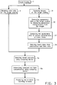
- Another variant of such exemplary system comprises: a) a color measurement device for obtaining color data of the target coating; b) an imaging device for obtaining one or more target images of the target coating; c) a computing device comprising a processor and a memory member; d) a color database containing known colorants associated with color characteristics, wherein the color database is accessible from the computing device; e) a flake database containing known flakes associated with appearance characteristics, wherein the flake database is accessible from the computing device; and f) one or more computing program products operatively residing in the memory member that causes the computing device to perform a computing process comprising the steps of: i) receiving the color data and the target images; ii) measuring appearance characteristics of the target coating from said target images to generate appearance data; iii) comparing the appearance data to appearance characteristics of known flakes stored in the flake database; iv) selecting from the flake database, one or more match flakes, flake combinations or flake ratios that have appearance characteristics matching the appearance data; v)
- the color measurement device, the appearance measurement device and the imaging device can further comprise means for providing illuminations, means for modulating and selecting illumination intensities, means for modulating illumination angles, or a combination thereof.
- the means for providing illuminations typically include a light source, such as, the IT3900 with a tungsten-halogen lamp EKE supplied by Illumination Technologies Inc., East Syracuse, New York and a fiber optic bundle A08025.60 supplied by Schott Fostec Inc., Auburn, New York that is capable of producing beams of illumination in the visible light range of from 400 nanometers to 700 nanometers at set intensities.
- the system which is preferably portable, is preferably provided with an enclosed extension to house the light source.
- the means for selecting an effective illumination intensity can be any conventional means, such as a voltage regulator that can change the current to the filament of the light source.
- the illumination intensity can be controlled in accordance with a conventional software program run from a computer to achieve the preset intensities.
- the computer used here to control the illumination intensity can be the same aforementioned computing device for receiving the image or a separate computer.
- the imaging device is preferably a digital imager such as a digital still camera, a digital video camera, a digital scanner, or a charge couple device (CCD) camera.
- a digital imager such as a digital still camera, a digital video camera, a digital scanner, or a charge couple device (CCD) camera.
- the methods and the systems of this invention can be used for measuring appearances of original automotive coatings (OEM coatings) and for matching the OEM coatings in repair and refinish of such OEM coatings.
- OEM coatings original automotive coatings
- Color data or appearance data of a target coating can be obtained at the same portion or at different portions of the target coating.
- Different portions of the target coating include different portions from a same piece of a substrate coated with the target coating and from different pieces of substrates coated with the same target coating.
- color data or appearance data can be obtained from different vehicles of the same model, same manufacturing year, and coated with the same coating.
- color data or appearance data can be obtained from different target panels coated with the same target coating.
- color measurement devices and imaging devices can be modified or reconfigured by those skilled in the art to be integrated with a computing device or to have a built-in computing device unit capable of processing and recording color or appearance data without transferring color data or images to a separate computing device.
- a car part from a Nissan Pilot vehicle coated with Steel Blue Paint had a coating damage and was used for coating repair.
- the car part was a cut-off metal from the vehicle body.
- the paint color code for the Steel Blue Paint of the vehicle was B533M.
- the car part was imaged with two preset illumination intensities at a fixed illumination angle, perpendicular (0°) to the surface of the coated area to generate coating images. Each image was measured at one high and one low threshold levels to generate appearance data of the vehicle coating.
- a coating composition was prepared based on the formula and used to repair the coating damage according to well known coating repair process.
- the formula can be adjusted based on standard color adjustment process.
- a Nissan Pilot vehicle coated with Steel Blue Paint has a coating damage and is in need for coating repair.
- the vehicle has a paint color code B533M.
- a coated area of the vehicle adjacent to the damaged coating is imaged with two preset illumination intensities at a fixed illumination angle, perpendicular (0°) to the surface of the coated area to generate coating images. Each image is measured at one high and one low threshold levels to generate appearance data of the vehicle coating.
- the coating images are measured with the same process and flakes are selected to produce matching formulas as described in Example 1.
- the coating damage is repaired as described in Example 1.
- Example 2 The same car part as in Example 1 was analyzed using conventional visual effect pigment identification techniques by an experienced shader.
- the shader selected a 90/10 blend of 2 aluminum flakes, one being a fine bright type and the other being a medium aluminum. Color data were obtained using the same spectrophotometer. When the 90/10 blend was combined with the color data, using the same traditional automated formulation algorithm, a color formula was produced. However, a coating prepared based on the color formula did not provide acceptable appearance match.
Landscapes
- Physics & Mathematics (AREA)
- Spectroscopy & Molecular Physics (AREA)
- General Physics & Mathematics (AREA)
- Spectrometry And Color Measurement (AREA)
- Investigating Or Analysing Materials By Optical Means (AREA)
- Paints Or Removers (AREA)
- Pigments, Carbon Blacks, Or Wood Stains (AREA)
Applications Claiming Priority (2)
| Application Number | Priority Date | Filing Date | Title |
|---|---|---|---|
| US90276107P | 2007-02-21 | 2007-02-21 | |
| PCT/US2008/002283 WO2008103405A1 (en) | 2007-02-21 | 2008-02-21 | Automatic selection of colorants and flakes for matching coating color and appearance |
Publications (3)
| Publication Number | Publication Date |
|---|---|
| EP2130013A1 EP2130013A1 (en) | 2009-12-09 |
| EP2130013A4 EP2130013A4 (en) | 2013-12-11 |
| EP2130013B1 true EP2130013B1 (en) | 2019-05-15 |
Family
ID=39710391
Family Applications (1)
| Application Number | Title | Priority Date | Filing Date |
|---|---|---|---|
| EP08725875.2A Active EP2130013B1 (en) | 2007-02-21 | 2008-02-21 | Automatic selection of colorants and flakes for matching coating color and appearance |
Country Status (5)
| Country | Link |
|---|---|
| EP (1) | EP2130013B1 (enExample) |
| JP (1) | JP2010519385A (enExample) |
| CN (1) | CN101617205B (enExample) |
| MX (1) | MX2009008865A (enExample) |
| WO (1) | WO2008103405A1 (enExample) |
Families Citing this family (23)
| Publication number | Priority date | Publication date | Assignee | Title |
|---|---|---|---|---|
| WO2011163583A1 (en) * | 2010-06-25 | 2011-12-29 | E. I. Du Pont De Nemours And Company | System for producing and delivering matching color coating and use thereof |
| EP2721542B1 (en) | 2011-06-20 | 2019-09-18 | Coatings Foreign IP Co. LLC | Method for matching sparkle appearance of coatings |
| WO2013013236A2 (en) * | 2011-07-21 | 2013-01-24 | E. I. Du Pont De Nemours And Company | Low gloss metallic color coating |
| EP2761517B1 (en) * | 2011-09-30 | 2023-07-05 | Axalta Coating Systems GmbH | Method for matching color and appearance of coatings containing effect pigments |
| US8760660B2 (en) | 2011-11-01 | 2014-06-24 | Axalta Coating Systems Ip Co., Llc | Process for predicting amount of coarse flakes in coating compositions by wet color measurement |
| EP2773942B1 (en) * | 2011-11-01 | 2022-05-18 | Axalta Coating Systems GmbH | Process for predicting tint strength of coating compositions by wet color measurement |
| WO2013126544A1 (en) * | 2012-02-21 | 2013-08-29 | U.S. Coatings Ip Co. Llc | Device for predicting amount of coarse flakes in coating compositions by wet color measurement |
| US9849431B2 (en) | 2012-07-13 | 2017-12-26 | Ppg Industries Ohio, Inc. | System and method for automated production, application and evaluation of coating compositions |
| US10178351B2 (en) | 2012-09-19 | 2019-01-08 | Ppg Industries Ohio, Inc. | Multi-angular color, opacity, pigment characterization and texture analysis of a painted surface via visual and/or instrumental techniques |
| WO2014135503A1 (en) * | 2013-03-07 | 2014-09-12 | Akzo Nobel Coatings International B.V. | Process for matching paint |
| CN104572911A (zh) * | 2014-12-26 | 2015-04-29 | 浙江理工大学 | 一种纺前着色纤维测配色方法 |
| US10613727B2 (en) | 2016-02-19 | 2020-04-07 | Ppg Industries Ohio, Inc. | Color and texture match ratings for optimal match selection |
| US9818205B2 (en) | 2016-02-19 | 2017-11-14 | Ppg Industries Ohio, Inc. | Simplified texture comparison engine |
| CN106994437B (zh) * | 2017-05-19 | 2020-08-04 | 安徽鹰龙工业设计有限公司 | 基于图像识别技术的汽车油漆修复方法及设备 |
| US11062479B2 (en) | 2017-12-06 | 2021-07-13 | Axalta Coating Systems Ip Co., Llc | Systems and methods for matching color and appearance of target coatings |
| US10970879B2 (en) * | 2018-04-26 | 2021-04-06 | Ppg Industries Ohio, Inc. | Formulation systems and methods employing target coating data results |
| US11080552B2 (en) * | 2018-09-18 | 2021-08-03 | Axalta Coating Systems Ip Co., Llc | Systems and methods for paint match simulation |
| CN113396318B (zh) * | 2019-02-05 | 2023-04-21 | Ppg工业俄亥俄公司 | 基于光的量角器及其用于检测与物理涂层相关联的颜色的用途 |
| MX2022003389A (es) | 2019-09-19 | 2022-04-19 | Ppg Ind Ohio Inc | Sistemas y metodos para mapear recubrimientos a un espacio de apariencia espacial. |
| US12100171B2 (en) * | 2019-12-31 | 2024-09-24 | Axalta Coating Systems Ip Co., Llc | Systems and methods for matching color and appearance of target coatings |
| JP7417789B2 (ja) | 2020-09-04 | 2024-01-18 | サン ケミカル コーポレイション | 完全統合型デジタル色管理システム |
| US20240184952A1 (en) * | 2021-03-17 | 2024-06-06 | Basf Coatings Gmbh | A method and a system for predicting the properties of coating layers and substrates comprising said coating layers |
| EP4422806A4 (en) * | 2021-10-25 | 2025-08-06 | Swimc Llc | METHOD AND SYSTEM FOR DETERMINING A COLOR MATCH FOR SURFACE COATINGS |
Citations (1)
| Publication number | Priority date | Publication date | Assignee | Title |
|---|---|---|---|---|
| US20060181707A1 (en) * | 2003-05-07 | 2006-08-17 | Gibson Mark A | Method of producing matched coating composition and device used therefor |
Family Cites Families (12)
| Publication number | Priority date | Publication date | Assignee | Title |
|---|---|---|---|---|
| US5231472A (en) | 1991-09-16 | 1993-07-27 | Ppg Industries, Inc. | Color matching and characterization of surface coatings |
| JP3234753B2 (ja) * | 1994-09-20 | 2001-12-04 | 本田技研工業株式会社 | 光輝顔料含有塗膜の色調判定方法 |
| JP3986117B2 (ja) * | 1997-05-22 | 2007-10-03 | 日本ペイント株式会社 | 自動車補修用塗料の調色装置 |
| JP2001091358A (ja) * | 1999-09-24 | 2001-04-06 | Jasco Corp | 調色方法および装置 |
| DE60009553T3 (de) * | 1999-12-17 | 2013-03-21 | Ppg Industries Ohio, Inc. | Rechnerimplementiertes Verfahren und Vorrichtung zur Anpassung der Farbe eines Anstriches |
| JP3626387B2 (ja) * | 2000-02-04 | 2005-03-09 | 関西ペイント株式会社 | コンピュータ調色装置及びこの装置を用いた塗料の調色方法 |
| EP1139234A1 (en) | 2000-03-28 | 2001-10-04 | E.I. Dupont De Nemours And Company | Color matching method for automotive refinishing |
| JP4731739B2 (ja) * | 2000-06-16 | 2011-07-27 | 大日精化工業株式会社 | Ccm計算システム、ccm計算方法および記録媒体 |
| CA2384127A1 (en) * | 2000-07-07 | 2002-01-17 | Kansai Paint Co., Ltd. | Toning method of paint having brilliant feeling |
| US6952265B2 (en) * | 2003-06-12 | 2005-10-04 | E. I. Du Pont De Nemours And Company | Method of characterization of surface coating containing metallic flakes and device used therein |
| JP4520775B2 (ja) * | 2003-08-19 | 2010-08-11 | ナトコ株式会社 | 非隠蔽性塗料の色合わせ方法、塗装物の製造方法、非隠蔽性塗料の色合わせ装置、塗装物製造装置、及びそのプログラム |
| JP2005094353A (ja) * | 2003-09-17 | 2005-04-07 | Dainichiseika Color & Chem Mfg Co Ltd | Ccm計算システム、ccm計算方法、プログラムおよび記録媒体 |
-
2008
- 2008-02-21 CN CN200880005833XA patent/CN101617205B/zh not_active Expired - Fee Related
- 2008-02-21 MX MX2009008865A patent/MX2009008865A/es active IP Right Grant
- 2008-02-21 EP EP08725875.2A patent/EP2130013B1/en active Active
- 2008-02-21 WO PCT/US2008/002283 patent/WO2008103405A1/en not_active Ceased
- 2008-02-21 JP JP2009550910A patent/JP2010519385A/ja not_active Ceased
Patent Citations (1)
| Publication number | Priority date | Publication date | Assignee | Title |
|---|---|---|---|---|
| US20060181707A1 (en) * | 2003-05-07 | 2006-08-17 | Gibson Mark A | Method of producing matched coating composition and device used therefor |
Also Published As
| Publication number | Publication date |
|---|---|
| EP2130013A1 (en) | 2009-12-09 |
| JP2010519385A (ja) | 2010-06-03 |
| MX2009008865A (es) | 2009-08-28 |
| EP2130013A4 (en) | 2013-12-11 |
| CN101617205A (zh) | 2009-12-30 |
| CN101617205B (zh) | 2013-07-10 |
| WO2008103405A1 (en) | 2008-08-28 |
Similar Documents
| Publication | Publication Date | Title |
|---|---|---|
| EP2130013B1 (en) | Automatic selection of colorants and flakes for matching coating color and appearance | |
| US8407014B2 (en) | Automatic selection of colorants and flakes for matching coating color and appearance | |
| EP2082201B1 (en) | Method for matching color and appearance of a coating containing effect pigments | |
| US11080552B2 (en) | Systems and methods for paint match simulation | |
| US8270699B2 (en) | Method for measuring coating appearance and the use thereof | |
| US9734590B2 (en) | Process for matching color and appearance of coatings | |
| US7743055B2 (en) | Digital display of color and appearance and the use thereof | |
| US7747615B2 (en) | System for color match and digital color display | |
| US8909574B2 (en) | Systems for matching sparkle appearance of coatings | |
| US12299818B2 (en) | Visualizing the appearance of at least two materials in a hetergeneous measurement environment | |
| WO2013049796A1 (en) | System for matching color and appearance of coatings containing effect pigments | |
| HK1140256A (en) | Automatic selection of colorants and flakes for matching coating color and appearance |
Legal Events
| Date | Code | Title | Description |
|---|---|---|---|
| PUAI | Public reference made under article 153(3) epc to a published international application that has entered the european phase |
Free format text: ORIGINAL CODE: 0009012 |
|
| 17P | Request for examination filed |
Effective date: 20090821 |
|
| AK | Designated contracting states |
Kind code of ref document: A1 Designated state(s): AT BE BG CH CY CZ DE DK EE ES FI FR GB GR HR HU IE IS IT LI LT LU LV MC MT NL NO PL PT RO SE SI SK TR |
|
| DAX | Request for extension of the european patent (deleted) | ||
| RAP1 | Party data changed (applicant data changed or rights of an application transferred) |
Owner name: COATINGS FOREIGN IP CO. LLC |
|
| A4 | Supplementary search report drawn up and despatched |
Effective date: 20131111 |
|
| RIC1 | Information provided on ipc code assigned before grant |
Ipc: G01J 3/50 20060101ALI20131105BHEP Ipc: G01J 3/46 20060101AFI20131105BHEP |
|
| 17Q | First examination report despatched |
Effective date: 20160322 |
|
| GRAP | Despatch of communication of intention to grant a patent |
Free format text: ORIGINAL CODE: EPIDOSNIGR1 |
|
| STAA | Information on the status of an ep patent application or granted ep patent |
Free format text: STATUS: GRANT OF PATENT IS INTENDED |
|
| INTG | Intention to grant announced |
Effective date: 20181221 |
|
| GRAS | Grant fee paid |
Free format text: ORIGINAL CODE: EPIDOSNIGR3 |
|
| GRAA | (expected) grant |
Free format text: ORIGINAL CODE: 0009210 |
|
| STAA | Information on the status of an ep patent application or granted ep patent |
Free format text: STATUS: THE PATENT HAS BEEN GRANTED |
|
| AK | Designated contracting states |
Kind code of ref document: B1 Designated state(s): AT BE BG CH CY CZ DE DK EE ES FI FR GB GR HR HU IE IS IT LI LT LU LV MC MT NL NO PL PT RO SE SI SK TR |
|
| REG | Reference to a national code |
Ref country code: CH Ref legal event code: EP Ref country code: GB Ref legal event code: FG4D |
|
| REG | Reference to a national code |
Ref country code: DE Ref legal event code: R096 Ref document number: 602008060086 Country of ref document: DE |
|
| REG | Reference to a national code |
Ref country code: IE Ref legal event code: FG4D |
|
| REG | Reference to a national code |
Ref country code: NL Ref legal event code: MP Effective date: 20190515 |
|
| REG | Reference to a national code |
Ref country code: LT Ref legal event code: MG4D |
|
| PG25 | Lapsed in a contracting state [announced via postgrant information from national office to epo] |
Ref country code: NO Free format text: LAPSE BECAUSE OF FAILURE TO SUBMIT A TRANSLATION OF THE DESCRIPTION OR TO PAY THE FEE WITHIN THE PRESCRIBED TIME-LIMIT Effective date: 20190815 Ref country code: LT Free format text: LAPSE BECAUSE OF FAILURE TO SUBMIT A TRANSLATION OF THE DESCRIPTION OR TO PAY THE FEE WITHIN THE PRESCRIBED TIME-LIMIT Effective date: 20190515 Ref country code: ES Free format text: LAPSE BECAUSE OF FAILURE TO SUBMIT A TRANSLATION OF THE DESCRIPTION OR TO PAY THE FEE WITHIN THE PRESCRIBED TIME-LIMIT Effective date: 20190515 Ref country code: NL Free format text: LAPSE BECAUSE OF FAILURE TO SUBMIT A TRANSLATION OF THE DESCRIPTION OR TO PAY THE FEE WITHIN THE PRESCRIBED TIME-LIMIT Effective date: 20190515 Ref country code: SE Free format text: LAPSE BECAUSE OF FAILURE TO SUBMIT A TRANSLATION OF THE DESCRIPTION OR TO PAY THE FEE WITHIN THE PRESCRIBED TIME-LIMIT Effective date: 20190515 Ref country code: HR Free format text: LAPSE BECAUSE OF FAILURE TO SUBMIT A TRANSLATION OF THE DESCRIPTION OR TO PAY THE FEE WITHIN THE PRESCRIBED TIME-LIMIT Effective date: 20190515 Ref country code: PT Free format text: LAPSE BECAUSE OF FAILURE TO SUBMIT A TRANSLATION OF THE DESCRIPTION OR TO PAY THE FEE WITHIN THE PRESCRIBED TIME-LIMIT Effective date: 20190915 Ref country code: FI Free format text: LAPSE BECAUSE OF FAILURE TO SUBMIT A TRANSLATION OF THE DESCRIPTION OR TO PAY THE FEE WITHIN THE PRESCRIBED TIME-LIMIT Effective date: 20190515 |
|
| PG25 | Lapsed in a contracting state [announced via postgrant information from national office to epo] |
Ref country code: LV Free format text: LAPSE BECAUSE OF FAILURE TO SUBMIT A TRANSLATION OF THE DESCRIPTION OR TO PAY THE FEE WITHIN THE PRESCRIBED TIME-LIMIT Effective date: 20190515 Ref country code: GR Free format text: LAPSE BECAUSE OF FAILURE TO SUBMIT A TRANSLATION OF THE DESCRIPTION OR TO PAY THE FEE WITHIN THE PRESCRIBED TIME-LIMIT Effective date: 20190816 Ref country code: BG Free format text: LAPSE BECAUSE OF FAILURE TO SUBMIT A TRANSLATION OF THE DESCRIPTION OR TO PAY THE FEE WITHIN THE PRESCRIBED TIME-LIMIT Effective date: 20190815 |
|
| REG | Reference to a national code |
Ref country code: AT Ref legal event code: MK05 Ref document number: 1133995 Country of ref document: AT Kind code of ref document: T Effective date: 20190515 |
|
| PG25 | Lapsed in a contracting state [announced via postgrant information from national office to epo] |
Ref country code: RO Free format text: LAPSE BECAUSE OF FAILURE TO SUBMIT A TRANSLATION OF THE DESCRIPTION OR TO PAY THE FEE WITHIN THE PRESCRIBED TIME-LIMIT Effective date: 20190515 Ref country code: CZ Free format text: LAPSE BECAUSE OF FAILURE TO SUBMIT A TRANSLATION OF THE DESCRIPTION OR TO PAY THE FEE WITHIN THE PRESCRIBED TIME-LIMIT Effective date: 20190515 Ref country code: SK Free format text: LAPSE BECAUSE OF FAILURE TO SUBMIT A TRANSLATION OF THE DESCRIPTION OR TO PAY THE FEE WITHIN THE PRESCRIBED TIME-LIMIT Effective date: 20190515 Ref country code: DK Free format text: LAPSE BECAUSE OF FAILURE TO SUBMIT A TRANSLATION OF THE DESCRIPTION OR TO PAY THE FEE WITHIN THE PRESCRIBED TIME-LIMIT Effective date: 20190515 Ref country code: EE Free format text: LAPSE BECAUSE OF FAILURE TO SUBMIT A TRANSLATION OF THE DESCRIPTION OR TO PAY THE FEE WITHIN THE PRESCRIBED TIME-LIMIT Effective date: 20190515 Ref country code: AT Free format text: LAPSE BECAUSE OF FAILURE TO SUBMIT A TRANSLATION OF THE DESCRIPTION OR TO PAY THE FEE WITHIN THE PRESCRIBED TIME-LIMIT Effective date: 20190515 |
|
| REG | Reference to a national code |
Ref country code: DE Ref legal event code: R097 Ref document number: 602008060086 Country of ref document: DE |
|
| PG25 | Lapsed in a contracting state [announced via postgrant information from national office to epo] |
Ref country code: IT Free format text: LAPSE BECAUSE OF FAILURE TO SUBMIT A TRANSLATION OF THE DESCRIPTION OR TO PAY THE FEE WITHIN THE PRESCRIBED TIME-LIMIT Effective date: 20190515 |
|
| PLBE | No opposition filed within time limit |
Free format text: ORIGINAL CODE: 0009261 |
|
| STAA | Information on the status of an ep patent application or granted ep patent |
Free format text: STATUS: NO OPPOSITION FILED WITHIN TIME LIMIT |
|
| PG25 | Lapsed in a contracting state [announced via postgrant information from national office to epo] |
Ref country code: TR Free format text: LAPSE BECAUSE OF FAILURE TO SUBMIT A TRANSLATION OF THE DESCRIPTION OR TO PAY THE FEE WITHIN THE PRESCRIBED TIME-LIMIT Effective date: 20190515 |
|
| 26N | No opposition filed |
Effective date: 20200218 |
|
| PG25 | Lapsed in a contracting state [announced via postgrant information from national office to epo] |
Ref country code: PL Free format text: LAPSE BECAUSE OF FAILURE TO SUBMIT A TRANSLATION OF THE DESCRIPTION OR TO PAY THE FEE WITHIN THE PRESCRIBED TIME-LIMIT Effective date: 20190515 |
|
| PG25 | Lapsed in a contracting state [announced via postgrant information from national office to epo] |
Ref country code: SI Free format text: LAPSE BECAUSE OF FAILURE TO SUBMIT A TRANSLATION OF THE DESCRIPTION OR TO PAY THE FEE WITHIN THE PRESCRIBED TIME-LIMIT Effective date: 20190515 |
|
| REG | Reference to a national code |
Ref country code: CH Ref legal event code: PL |
|
| GBPC | Gb: european patent ceased through non-payment of renewal fee |
Effective date: 20200221 |
|
| REG | Reference to a national code |
Ref country code: BE Ref legal event code: MM Effective date: 20200229 |
|
| PG25 | Lapsed in a contracting state [announced via postgrant information from national office to epo] |
Ref country code: LU Free format text: LAPSE BECAUSE OF NON-PAYMENT OF DUE FEES Effective date: 20200221 Ref country code: MC Free format text: LAPSE BECAUSE OF FAILURE TO SUBMIT A TRANSLATION OF THE DESCRIPTION OR TO PAY THE FEE WITHIN THE PRESCRIBED TIME-LIMIT Effective date: 20190515 |
|
| PG25 | Lapsed in a contracting state [announced via postgrant information from national office to epo] |
Ref country code: CH Free format text: LAPSE BECAUSE OF NON-PAYMENT OF DUE FEES Effective date: 20200229 Ref country code: LI Free format text: LAPSE BECAUSE OF NON-PAYMENT OF DUE FEES Effective date: 20200229 |
|
| PG25 | Lapsed in a contracting state [announced via postgrant information from national office to epo] |
Ref country code: FR Free format text: LAPSE BECAUSE OF NON-PAYMENT OF DUE FEES Effective date: 20200229 Ref country code: GB Free format text: LAPSE BECAUSE OF NON-PAYMENT OF DUE FEES Effective date: 20200221 Ref country code: IE Free format text: LAPSE BECAUSE OF NON-PAYMENT OF DUE FEES Effective date: 20200221 |
|
| PG25 | Lapsed in a contracting state [announced via postgrant information from national office to epo] |
Ref country code: BE Free format text: LAPSE BECAUSE OF NON-PAYMENT OF DUE FEES Effective date: 20200229 |
|
| REG | Reference to a national code |
Ref country code: DE Ref legal event code: R081 Ref document number: 602008060086 Country of ref document: DE Owner name: AXALTA COATING SYSTEMS GMBH, CH Free format text: FORMER OWNER: COATINGS FOREIGN IP CO. LLC, WILMINGTON, DEL., US |
|
| PG25 | Lapsed in a contracting state [announced via postgrant information from national office to epo] |
Ref country code: MT Free format text: LAPSE BECAUSE OF FAILURE TO SUBMIT A TRANSLATION OF THE DESCRIPTION OR TO PAY THE FEE WITHIN THE PRESCRIBED TIME-LIMIT Effective date: 20190515 Ref country code: CY Free format text: LAPSE BECAUSE OF FAILURE TO SUBMIT A TRANSLATION OF THE DESCRIPTION OR TO PAY THE FEE WITHIN THE PRESCRIBED TIME-LIMIT Effective date: 20190515 |
|
| PG25 | Lapsed in a contracting state [announced via postgrant information from national office to epo] |
Ref country code: IS Free format text: LAPSE BECAUSE OF FAILURE TO SUBMIT A TRANSLATION OF THE DESCRIPTION OR TO PAY THE FEE WITHIN THE PRESCRIBED TIME-LIMIT Effective date: 20190915 |
|
| P01 | Opt-out of the competence of the unified patent court (upc) registered |
Effective date: 20230504 |
|
| PGFP | Annual fee paid to national office [announced via postgrant information from national office to epo] |
Ref country code: DE Payment date: 20240228 Year of fee payment: 17 |
|
| REG | Reference to a national code |
Ref country code: DE Ref legal event code: R119 Ref document number: 602008060086 Country of ref document: DE |
|
| PG25 | Lapsed in a contracting state [announced via postgrant information from national office to epo] |
Ref country code: DE Free format text: LAPSE BECAUSE OF NON-PAYMENT OF DUE FEES Effective date: 20250902 |