EP2128372A2 - Plastic window or door and method for production of same - Google Patents
Plastic window or door and method for production of same Download PDFInfo
- Publication number
- EP2128372A2 EP2128372A2 EP09006967A EP09006967A EP2128372A2 EP 2128372 A2 EP2128372 A2 EP 2128372A2 EP 09006967 A EP09006967 A EP 09006967A EP 09006967 A EP09006967 A EP 09006967A EP 2128372 A2 EP2128372 A2 EP 2128372A2
- Authority
- EP
- European Patent Office
- Prior art keywords
- locking bar
- fitting groove
- spars
- plastic
- inwardly projecting
- Prior art date
- Legal status (The legal status is an assumption and is not a legal conclusion. Google has not performed a legal analysis and makes no representation as to the accuracy of the status listed.)
- Granted
Links
Images


Classifications
-
- E—FIXED CONSTRUCTIONS
- E06—DOORS, WINDOWS, SHUTTERS, OR ROLLER BLINDS IN GENERAL; LADDERS
- E06B—FIXED OR MOVABLE CLOSURES FOR OPENINGS IN BUILDINGS, VEHICLES, FENCES OR LIKE ENCLOSURES IN GENERAL, e.g. DOORS, WINDOWS, BLINDS, GATES
- E06B3/00—Window sashes, door leaves, or like elements for closing wall or like openings; Layout of fixed or moving closures, e.g. windows in wall or like openings; Features of rigidly-mounted outer frames relating to the mounting of wing frames
- E06B3/96—Corner joints or edge joints for windows, doors, or the like frames or wings
- E06B3/9604—Welded or soldered joints
- E06B3/9608—Mitre joints
-
- E—FIXED CONSTRUCTIONS
- E06—DOORS, WINDOWS, SHUTTERS, OR ROLLER BLINDS IN GENERAL; LADDERS
- E06B—FIXED OR MOVABLE CLOSURES FOR OPENINGS IN BUILDINGS, VEHICLES, FENCES OR LIKE ENCLOSURES IN GENERAL, e.g. DOORS, WINDOWS, BLINDS, GATES
- E06B3/00—Window sashes, door leaves, or like elements for closing wall or like openings; Layout of fixed or moving closures, e.g. windows in wall or like openings; Features of rigidly-mounted outer frames relating to the mounting of wing frames
- E06B3/96—Corner joints or edge joints for windows, doors, or the like frames or wings
Definitions
- the present invention relates to a plastic window or a plastic door with at least two miter-cut spars, which are assembled to produce a connecting corner butt to joint and interconnected, wherein in the connecting corner forming spars each a fitting groove is formed, the two on opposite side walls of the Tray formed, inwardly projecting wall sections comprises, at least one locking bar is slidably mounted in at least one of the fitting grooves and the locking bar is at least partially disposed under the two inwardly projecting wall sections of the fitting, so that leakage of the locking bar from the fitting groove in a direction transverse to Longitudinal extension of the fitting groove is prevented. Furthermore, the invention is directed to a method for producing plastic windows or doors.
- Plastic windows or doors of the type mentioned are usually made by first cutting the individual longitudinal and transverse bars of the frame miter, then the trimmed bars are struck together in bursts, whereupon the adjoining bars are connected to each other, for example by a welding process ,
- the welding process comprises a rest phase following the actual welding operation during which the plastic material has to cool down.
- this resting phase (cooling phase) is an undesirable dead time, since the person performing the assembly and welding of the individual spars during the resting phase no further Manufacturing steps on the frame can perform and thus the idle phase must wait idly.
- this object is achieved by a method for producing plastic windows or doors, in which a plurality of at least partially made of plastic spars are mitred respectively at its two ends in a first method step, wherein at least in a spar formed for receiving a locking bar Bescariasut is provided in a subsequent process step, the locking bar is inserted over a frontal opening of the spar in the fitting groove lengthwise, in a subsequent process step, the trimmed spars are assembled butt to thrust to form a wing and in a subsequent process step the composite spars are interconnected.
- An inventive plastic window or a plastic door of the type mentioned above is characterized in that each formed on the same side of the fitting grooves on the side walls of the fitting, inwardly projecting wall portions adjacent to each other at the connection corner and thereby each a closed form around the connecting corner running around, inwardly projecting total wall portion.
- the locking bars are not used for the first time after assembly and connecting the individual spars in the finished sash, but the locking bars are already used in the fitting, while the spars are still separated.
- the fitting grooves are still formed open on the frontal, mitered ends of the spars, so that at both ends of the spar end-side openings are formed, in which the locking bars can be inserted lengthwise.
- the insertion of the locking bars in the fitting groove can take place while the previously processed frame is in its quiescent phase (cooling phase). In this way it is achieved that this resting phase means no dead time for the mechanic, but that during this rest phase already preparatory actions for the production of the next frame, namely the insertion of the locking bars in the still loose individual spars, are performed.
- the finished frame connected to a unit can be removed from the welding device and it can be already pre-equipped with the locking bars single struts of the frame to be subsequently produced inserted into the welding device.
- the dead time described above can be prevented in this way and the profitability of the production can be increased.
- the locking bars are also automatically secured in the fitting groove, since a limit for the locking bars is formed due to the adjacent in the region of the connection corner and closed around the connection corner running inwardly projecting total wall sections, prevents the complete emergence of the locking bars from the fitting becomes.
- a transmission is used in a direction transverse to the locking bar in the fitting groove and connected to the locking bar in a further subsequent step.
- the connection can be made via a conventional connection, for example, a toothing.
- a toothing which may be in the form of a so-called "rack" cooperating with a rack, for example, an adjustment of the effective length of the locking bar is possible.
- the gearbox already directly after the insertion of the locking bars and only then to connect the individual struts.
- the device for connecting the individual spars must be designed according to also accommodate the geared spar and edit.
- the locking bar is at least partially inserted under two formed on opposite side walls of the fitting groove, inwardly projecting wall portions of the fitting groove, so that leakage of the locking bar from the fitting groove in a direction transverse to the longitudinal extent of the fitting is prevented.
- the locking bar engages under the inwardly projecting wall sections, in particular with its two lateral longitudinal edges.
- a longitudinal groove may be formed on the lateral longitudinal edges of the locking bar, in which engage the inwardly projecting wall sections.
- the locking bar has at least partially an H-shaped cross section.
- the locking bar is formed flat-rod-shaped and is guided between said, inwardly projecting wall sections and further, closer to the groove bottom, inwardly projecting wall sections.
- a guide between the inwardly projecting wall sections and the groove bottom itself is basically possible.
- the locking bar is automatically secured in a direction perpendicular to the longitudinal extent of the fitting groove and not by additional elements, such as a faceplate or additional fasteners against leakage from the fitting groove must be secured. Since in the longitudinal direction of the fitting groove also a complete leakage of the locking bar is prevented by the abutting at the connecting corner inwardly projecting wall sections, thus securing the locking bar is realized in a very simple and cost-effective manner.
- the composite spars are welded together.
- another type of connection for example gluing, is possible.
- a locking bar is used with at least partially H-shaped cross-section.
- the locking bar comprises at least one bar exclusion and / or a locking pin and / or a corner deflection. This ensures that after insertion of the locking bar and assembly of the individual spars and insertion of the gearbox a fully functional frame with fitting arrangement is created.
- several, in particular all spars comprise a fitting groove, locking bars being inserted into a plurality of, in particular, all fitting grooves.
- This is particularly useful when using the method according to the invention rotary / tilting vanes or wings to be produced with additional locks on the upper and / or lower cross member and / or on the belt-side rail.
- the locking bars which are already inserted into the fitting grooves in this case before the individual spars are put together, can then be joined after connecting the spars, e.g. be subsequently connected by externally patch Eckumlenk Institute.
- the width of the rod exclusion is smaller than the clear width between the inwardly projecting wall sections. This ensures that the bar exclusion despite the closed running around the connection corner, inwardly projecting total wall sections from the fitting groove is extendable to fulfill its locking function.
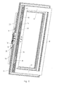
- Fig. 1 shows a partial perspective view of a window frame 1, which was not made according to the invention.
- the window frame 1 comprises two spars 2 which have been cut to a miter and assembled to produce a connecting corner 3 butt to joint and then welded together in a conventional manner.
- a locking bar 11 is slidably disposed, on whose longitudinal sides 12, 13 longitudinal grooves 14, 15 are formed, projecting into the projecting wall portion 8 and the not shown, inwardly projecting wall portion, thereby forming a guide for the locking bar 11 becomes.
- the inwardly projecting wall sections 8, 9, 10 and not shown inwardly projecting wall portion are cut obliquely in the region of the connecting corner 3, whereby an insertion opening 16 for the Lock bar 11 is formed.
- the production of the window frame 1 is time-consuming, since after welding the two spars 2 first a cooling phase must be awaited before the inwardly projecting wall sections 8, 9, 10 can be cut off obliquely and the locking bar 11 are inserted into the fitting groove 4 can.
- the Fig. 2 to 4 show a spar 17, which is equipped with two locking bars 18, before the spar 17 with further bars 19 (see Fig. 6 ) is connected.
- the spar 17 comprises an elongated fitting groove 20, which is open towards the forend of the spar 17 and opens at the two mitred ends 21 of the spar 17 in frontal openings 22.
- the locking bars 18 are inserted over the frontal openings 22 in the fitting groove 20 in length until they have their in Fig. 4 reach shown positions.
- Fig. 5 can be seen form on side walls 23, 24 of the fitting groove 20 formed, inwardly into the fitting groove 20 projecting wall sections 25, 26 guides for the locking bars 18. These each have an H-shaped cross-section with on the longitudinal sides 43, 44 of the Locking rods 18 formed longitudinal grooves 27, 28, in which protrude the inwardly projecting wall portions 25, 26 how it looks Fig. 5 is apparent.
- the locking bars 18 are guided in this way longitudinally displaceable in the fitting groove 20, at the same time a movement perpendicular to the longitudinal extension of the fitting groove 20 and thus also a removal of the locking bars 18 is prevented in such a direction.
- the generated wing 29 is already equipped with the locking bars 18 in this case.
- a gear 30 is inserted over the longitudinal opening of the fitting groove 20 in this, as it is in Fig. 7 is indicated by an arrow 31.
- the transmission 30 comprises a gearbox 32 and elongated cover rails 33 attached thereto, through which the fitting groove 20 is partially covered after assembly of the gearbox 30.
- tooth box 53 On the underside of the cover rails 33 connecting elements in the form of so-called tooth box 53 are provided, which with corresponding formed on the locking bars 18 teeth 34 (see Fig. 4 and 8th ) can be plugged together so that a positive connection in the longitudinal direction of the locking bars 18 is generated.
- the tooth boxes 53 are moved upon actuation of the transmission 30, whereby a corresponding longitudinal displacement of the locking bars 18 takes place.
- the transmission 30 After insertion of the transmission 30, this is secured by screws 35 to the spar 17. In principle, the screws 35 can also be omitted. In this case, the transmission 30 can be fastened, for example, by the same fastening screws used for fastening the actuating handle (not shown) of the transmission 30. An attachment via on the operating handle or its rosette provided in the gearbox engaging pins is conceivable. Since the locking bars 18 are already secured by the inwardly projecting wall portions 25, 26 against removal from the fitting groove 20, a further fixation of the locking bars 18 is not required.
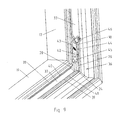
- Fig. 9 shows a partial perspective view of the wing 29 in the region of a connecting corner 36 produced by connecting the spar 17 with one of the spars 19.
- the spar 19 has a fitting groove 37 which is formed according to the fitting groove 20 of the spar 17.
- inwardly projecting wall portion 40, 41 are formed, since all the spars 17, 19 are usually cut from the originally same profile.
- Fig. 9 shows how out Fig. 9 can be seen, after assembling and connecting the spars 17, 19, the fitting grooves 20, 37 aligned at right angles to each other, so that the inwardly projecting wall portions 26 and 41 and the inwardly projecting wall portions 25th (please refer Fig. 5 ) and 40 abut each other in the region of the connecting corner 36 and in each case form a complete wall section extending inwardly around the connecting corner 36 and projecting inwards.
- the drive rod 18 According to an arrow 42 thus encounter the wall portions 25, 26 encompassing longitudinal sides 43, 44 of the drive rod 18 to the inwardly projecting wall portions 40, 41, thus forming limiting elements for the drive rods 18.
- the drive rods 18 are thus in a window designed according to the invention captive and installed dismantling.
- a bar exclusion 45 is formed at the end of the drive rod 18, whose width is less than the clear width between the inwardly projecting wall sections 40, 41 and 25, 26.
- the rod exclusion 45 pass through the inwardly projecting wall portion 40, 41 and cooperate in a conventional manner with a corresponding locking element on the frame.
- the laterally extending beyond the gear 30 cover rails can also be designed to be much shorter, so that the drive rods are ultimately visible almost over its entire length from the outside and thus optically form a cover of the fitting groove 20 without a cuff rail would be required.
- the cover rails are replaced by a uniform short cover plate 47 for the transmission 30.
- the coupling between the gear 30 and the illustrated drive rods 48 takes place via coupling elements 49, each a pin 50 which projects into corresponding receiving openings 51 in the drive rods 48.
- the coupling elements 49 comprise teeth 52, which are connected to transmission elements, not shown, of the transmission 30 for longitudinal displacement of the drive rods 48 via the transmission 30.
- the time required for the production of a plastic window or a plastic door is reduced and, on the other hand, the connecting corners of the inventively designed plastic windows or doors are visually appealing, the drive rods are simultaneously captive and dismantling installed.
Abstract
Description
Die vorliegende Erfindung betrifft ein Kunststofffenster oder eine Kunststofftür mit zumindest zwei auf Gehrung geschnittenen Holmen, die zum Erzeugen einer Verbindungsecke Stoß an Stoß zusammengesetzt und miteinander verbunden sind, wobei in den die Verbindungsecke bildenden Holmen jeweils eine Beschlagnut ausgebildet ist, die zwei an gegenüberliegenden Seitenwänden der Beschlagnut ausgebildete, nach innen ragende Wandabschnitte umfasst, zumindest in einer der Beschlagnuten wenigstens eine Riegelstange verschiebbar gelagert ist und die Riegelstange zumindest bereichsweise unter den zwei nach innen ragenden Wandabschnitten der Beschlagnut angeordnet ist, sodass ein Austreten der Riegelstange aus der Beschlagnut in einer Richtung quer zur Längserstreckung der Beschlagnut verhindert wird. Weiterhin ist die Erfindung auf ein Verfahren zum Herstellen von Kunststofffenstern oder -türen gerichtet.The present invention relates to a plastic window or a plastic door with at least two miter-cut spars, which are assembled to produce a connecting corner butt to joint and interconnected, wherein in the connecting corner forming spars each a fitting groove is formed, the two on opposite side walls of the Tray formed, inwardly projecting wall sections comprises, at least one locking bar is slidably mounted in at least one of the fitting grooves and the locking bar is at least partially disposed under the two inwardly projecting wall sections of the fitting, so that leakage of the locking bar from the fitting groove in a direction transverse to Longitudinal extension of the fitting groove is prevented. Furthermore, the invention is directed to a method for producing plastic windows or doors.
Kunststofffenster oder -türen der eingangs genannten Art werden üblicherweise hergestellt, indem zunächst die einzelnen Längs- und Querholme des Rahmens auf Gehrung geschnitten werden, anschließend die zurechtgeschnittenen Holme Stoß an Stoß aneinander angesetzt werden, woraufhin die aneinander anstoßenden Holme beispielsweise durch einen Schweißprozess miteinander verbunden werden. Der Schweißprozess umfasst dabei eine sich an den eigentlichen Schweißvorgang anschließende Ruhephase, während der das Kunststoffmaterial abkühlen muss. Bei dieser Ruhephase (Abkühlphase) handelt es sich um eine unerwünschte Totzeit, da die das Zusammensetzen und Verschweißen der einzelnen Holme durchführende Person während der Ruhephase keine weiteren Fertigungsschritte an dem Rahmen durchführen kann und somit die Ruhephase untätig abwarten muss.Plastic windows or doors of the type mentioned are usually made by first cutting the individual longitudinal and transverse bars of the frame miter, then the trimmed bars are struck together in bursts, whereupon the adjoining bars are connected to each other, for example by a welding process , The welding process comprises a rest phase following the actual welding operation during which the plastic material has to cool down. During this resting phase (cooling phase) is an undesirable dead time, since the person performing the assembly and welding of the individual spars during the resting phase no further Manufacturing steps on the frame can perform and thus the idle phase must wait idly.
Erst nach Ablauf der Ruhephase, die zusammen mit dem Schweißvorgang beispielsweise ca. 1 Minute dauert, werden in einem nachfolgenden Verfahrensschritt das Getriebe zusammen mit den Stulpschienen und daran befestigen Riegelstangen von oben in die Beschlagnut, das heißt in einer Richtung senkrecht zu deren Längserstreckung, eingesetzt. Anschließend werden die Stulpschienen zur Abdeckung der Beschlagnut mit Schrauben am Rahmen fixiert. Die Schrauben erstrecken sich dabei durch Langlöcher in den an den Stulpschienen verschiebbar befestigten Riegelstangen hindurch.Only after the end of the idle phase, which, for example, lasts approximately 1 minute together with the welding operation, in a subsequent method step, the gearbox together with the cuff rails and locking bars fastened thereto are inserted from above into the fitting groove, ie in a direction perpendicular to its longitudinal extent , Then the cuff rails to cover the fitting groove are fixed with screws on the frame. The screws extend through slots in the slidably mounted on the cuff rails locking bars.
Neben der beschriebenen Totzeit ist an dieser Herstellung nachteilig, dass zusätzlich zu den Riegelstangen Stulpschienen erforderlich sind und deren Befestigung durch Verschrauben einen zusätzlichen Arbeitsschritt erfordert.In addition to the dead time described is disadvantageous in this production that in addition to the locking bars cuff rails are required and their attachment by screwing requires an additional step.
Es ist auch möglich, anstelle der von oben in die Beschlagnut einzusetzenden Riegelstangen und der zusätzlichen Stulpschienen Riegelstangen zu verwenden, die nach dem Zusammensetzen und Verschweißen der einzelnen Holme von der Verbindungsecke aus in Längsrichtung in die Beschlagnut eingeschoben werden. Da die nach innen ragenden Wandabschnitte im Bereich der Verbindungsecke ein solches Einschieben verhindern, ist es dabei erforderlich, nach dem Zusammenbau der einzelnen Holme die nach innen ragenden Wandabschnitte im Bereich der Verbindungsecke schräg abzuschneiden, sodass im Bereich der Verbindungsecke eine Einführmöglichkeit für die Riegelstange geschaffen wird.It is also possible to use instead of the locking bars to be used from above in the fitting groove and the additional cuff rails, which are inserted after assembly and welding of the individual spars of the connecting corner in the longitudinal direction in the fitting groove. Since the inwardly projecting wall sections prevent such insertion in the region of the connecting corner, it is necessary to cut off the inwardly projecting wall sections in the region of the connecting corner after assembly of the individual spars, so that an insertion possibility for the locking bar is created in the region of the connecting corner ,
Nachteilig an dieser Variante ist neben der ebenfalls vorhandenen Totzeit, dass die Riegelstangen an den Verbindungsecken aus der Beschlagnut auch wieder vollständig austreten können, solange sie nicht anderweitig in der Beschlagnut gesichert sind. Außerdem verschlechtern die schräg abgeschnittenen Wandabschnitte das optische Erscheinungsbild der Fenster oder Türen.A disadvantage of this variant, in addition to the also existing dead time, that the locking bars on the connecting corners of the fitting groove can also emerge completely again, as long as they are not otherwise secured in the fitting. In addition, the obliquely cut wall sections deteriorate the visual appearance of the windows or doors.
Es ist eine Aufgabe der vorliegenden Erfindung ein Verfahren zum Herstellen von Kunststofffenstern oder -türen anzugeben, das kostengünstig durchführbar ist. Entsprechende Kunststofffenster oder -türen sollen kostengünstig und einfach herstellbar sein.It is an object of the present invention to provide a method for producing plastic windows or doors that is inexpensive to carry out. Corresponding plastic windows or doors should be inexpensive and easy to produce.
Erfindungsgemäß wird diese Aufgabe gelöst durch ein Verfahren zum Herstellen von Kunststofffenstern oder -türen, bei dem in einem ersten Verfahrensschritt mehrere zumindest teilweise aus Kunststoff bestehende Holme jeweils an ihren beiden Enden auf Gehrung geschnitten werden, wobei zumindest in einem Holm eine zur Aufnahme einer Riegelstange ausgebildete Beschlagnut vorgesehen ist, in einem darauf folgenden Verfahrensschritt die Riegelstange über eine stirnseitige Öffnung des Holms in die Beschlagnut der Länge nach eingeschoben wird, in einem darauf folgenden Verfahrensschritt die beschnittenen Holme jeweils Stoß an Stoß zu einem Flügel zusammengesetzt werden und in einem darauf folgenden Verfahrensschritt die zusammengesetzten Holme miteinander verbunden werden.According to the invention this object is achieved by a method for producing plastic windows or doors, in which a plurality of at least partially made of plastic spars are mitred respectively at its two ends in a first method step, wherein at least in a spar formed for receiving a locking bar Beschaltungsut is provided in a subsequent process step, the locking bar is inserted over a frontal opening of the spar in the fitting groove lengthwise, in a subsequent process step, the trimmed spars are assembled butt to thrust to form a wing and in a subsequent process step the composite spars are interconnected.
Ein erfindungsgemäßes Kunststofffenster oder eine Kunststofftür der eingangs genannten Art ist dadurch gekennzeichnet, dass die jeweils auf der gleichen Seite der Beschlagnuten an den Seitenwänden der Beschlagnuten ausgebildeten, nach innen ragenden Wandabschnitte an der Verbindungsecke aneinander angrenzen und dadurch jeweils einen geschlossen um die Verbindungsecke herumlaufenden, nach innen ragenden Gesamtwandabschnitt bilden.An inventive plastic window or a plastic door of the type mentioned above is characterized in that each formed on the same side of the fitting grooves on the side walls of the fitting, inwardly projecting wall portions adjacent to each other at the connection corner and thereby each a closed form around the connecting corner running around, inwardly projecting total wall portion.
Erfindungsgemäß werden somit erstmals die Riegelstangen nicht nach dem Zusammenbau und Verbinden der einzelnen Holme in den fertigen Flügelrahmen eingesetzt, sondern die Riegelstangen werden bereits in die Beschlagnut eingesetzt, während die Holme noch voneinander getrennt sind. In diesem Zustand sind an den stirnseitigen, auf Gehrung geschnittenen Enden der Holme die Beschlagnuten noch offen ausgebildet, sodass an beiden Enden des Holms stirnseitige Öffnungen gebildet sind, in die die Riegelstangen der Länge nach eingeschoben werden können. Erfindungsgemäß kann dabei das Einschieben der Riegelstangen in die Beschlagnut erfolgen, während sich der zuvor bearbeitete Rahmen in seiner Ruhephase (Abkühlphase) befindet. Auf diese Weise wird erreicht, dass diese Ruhephase keine Totzeit für den Monteur bedeutet, sondern dass während dieser Ruhephase bereits vorbereitende Handlungen für die Herstellung des nächsten Rahmens, nämlich das Einschieben der Riegelstangen in die noch losen Einzelholme, durchgeführt werden.According to the invention thus the locking bars are not used for the first time after assembly and connecting the individual spars in the finished sash, but the locking bars are already used in the fitting, while the spars are still separated. In this state, the fitting grooves are still formed open on the frontal, mitered ends of the spars, so that at both ends of the spar end-side openings are formed, in which the locking bars can be inserted lengthwise. According to the invention, the insertion of the locking bars in the fitting groove can take place while the previously processed frame is in its quiescent phase (cooling phase). In this way it is achieved that this resting phase means no dead time for the mechanic, but that during this rest phase already preparatory actions for the production of the next frame, namely the insertion of the locking bars in the still loose individual spars, are performed.
Ist die Ruhephase des zuerst hergestellten Rahmens beendet, kann der fertig zu einer Einheit verbundene Rahmen aus der Schweißvorrichtung entnommen werden und es können die bereits vorbereitend mit den Riegelstangen bestückten Einzelholme des nachfolgend herzustellenden Rahmens in die Schweißvorrichtung eingesetzt werden. Die eingangs beschriebene Totzeit kann auf diese Weise verhindert und die Wirtschaftlichkeit der Herstellung damit erhöht werden.If the resting phase of the frame produced first completed, the finished frame connected to a unit can be removed from the welding device and it can be already pre-equipped with the locking bars single struts of the frame to be subsequently produced inserted into the welding device. The dead time described above can be prevented in this way and the profitability of the production can be increased.
Darüber hinaus ist bei der erfindungsgemäßen Herstellung ein Abschneiden der nach innen ragenden Wandabschnitte zum Einführen der Riegelstangen nicht mehr erforderlich, da die Riegelstangen sich nach dem Verschweißen der Einzelholme bereits in den Beschlagnuten befinden. Somit kann dieser im Stand der Technik erforderliche zusätzliche Arbeitsschritt ebenfalls entfallen. Mit anderen Worten müssen die nach dem Zusammenbau der einzelnen Holme nach innen ragenden Wandabschnitte im Bereich der Verbindungsecke nicht schräg abgeschnitten werden, um im Bereich der Verbindungsecke eine Einführmöglichkeit für die Riegelstange zu schaffen. Eine Formgebung der Holme ist mit dem Verbinden abgeschlossen. Nach der Verbindung der Holme ist somit im Wesentlichen eine endgültige Kontur des Flügels geschaffen.In addition, in the production according to the invention, a cutting off of the inwardly projecting wall sections for the insertion of the locking bars is no longer necessary since the locking bars become welded after welding the single spars are already in the fittings. Thus, this required in the prior art additional operation can also be omitted. In other words, after the assembly of the individual spars inwardly projecting wall sections in the connection area must not be cut off obliquely to create an insertion possibility for the locking bar in the region of the connecting corner. A shaping of the spars is completed with the joining. After the connection of the spars thus a final contour of the wing is created substantially.
Letztlich sind die Riegelstangen in der Beschlagnut auch automatisch gesichert, da aufgrund der im Bereich der Verbindungsecke aneinander angrenzenden und geschlossen um die Verbindungsecke herumlaufenden, nach innen ragenden Gesamtwandabschnitte eine Begrenzung für die Riegelstangen gebildet wird, durch die ein vollständiges Austreten der Riegelstangen aus der Beschlagnut verhindert wird.Finally, the locking bars are also automatically secured in the fitting groove, since a limit for the locking bars is formed due to the adjacent in the region of the connection corner and closed around the connection corner running inwardly projecting total wall sections, prevents the complete emergence of the locking bars from the fitting becomes.
Nach einer vorteilhaften Ausführungsform des erfindungsgemäßen Verfahrens wird in einem weiteren darauf folgenden Verfahrensschritt ein Getriebe in einer Richtung quer zu der Riegelstange in die Beschlagnut eingesetzt und mit der Riegelstange verbunden. Die Verbindung kann dabei über eine übliche Verbindung, beispielsweise eine Verzahnung erfolgen. Durch eine solche Verzahnung, die in Form eines sogenannten mit einer Zahnstange zusammenwirkenden "Zahnkästchens" ausgebildet sein kann, ist beispielsweise eine Einstellung der wirksamen Länge der Riegelstange möglich. Grundsätzlich ist es auch denkbar, das Getriebe bereits direkt nach dem Einschieben der Riegelstangen einzusetzen und erst danach die Einzelholme zu verbinden. Allerdings muss dann die Vorrichtung zum Verbinden der Einzelholme entsprechend ausgebildet sein, auch den mit Getriebe versehenen Holm aufnehmen und bearbeiten zu können.According to an advantageous embodiment of the method according to the invention, a transmission is used in a direction transverse to the locking bar in the fitting groove and connected to the locking bar in a further subsequent step. The connection can be made via a conventional connection, for example, a toothing. By such a toothing, which may be in the form of a so-called "rack" cooperating with a rack, for example, an adjustment of the effective length of the locking bar is possible. In principle, it is also conceivable to use the gearbox already directly after the insertion of the locking bars and only then to connect the individual struts. However, then the device for connecting the individual spars must be designed according to also accommodate the geared spar and edit.
Nach einer weiteren bevorzugten Ausführungsform der Erfindung wird die Riegelstange zumindest bereichsweise unter zwei an gegenüberliegenden Seitenwänden der Beschlagnut ausgebildete, nach innen ragende Wandabschnitte der Beschlagnut eingeschoben, sodass ein Austreten der Riegelstange aus der Beschlagnut in einer Richtung quer zur Längserstreckung der Beschlagnut verhindert wird. Erfindungsgemäß untergreift somit die Riegelstange die nach innen ragenden Wandabschnitte insbesondere mit ihren beiden seitlichen Längskanten. Bevorzugt kann dabei an den seitlichen Längskanten der Riegelstange jeweils eine Längsnut ausgebildet sein, in die die nach innen ragenden Wandabschnitte eingreifen. Vorteilhaft besitzt dabei die Riegelstange zumindest bereichsweise einen H-förmigen Querschnitt. Es ist auch möglich, dass die Riegelstange flachstabförmig ausgebildet ist und zwischen den genannten, nach innen ragenden Wandabschnitten sowie weiteren, näher zum Nutboden hin angeordneten, nach innen ragenden Wandabschnitten geführt wird. Auch eine Führung zwischen den nach innen ragenden Wandabschnitten und dem Nutboden selbst ist grundsätzlich möglich.According to a further preferred embodiment of the invention, the locking bar is at least partially inserted under two formed on opposite side walls of the fitting groove, inwardly projecting wall portions of the fitting groove, so that leakage of the locking bar from the fitting groove in a direction transverse to the longitudinal extent of the fitting is prevented. Thus, according to the invention the locking bar engages under the inwardly projecting wall sections, in particular with its two lateral longitudinal edges. Preferably, in each case a longitudinal groove may be formed on the lateral longitudinal edges of the locking bar, in which engage the inwardly projecting wall sections. Advantageously, the locking bar has at least partially an H-shaped cross section. It is also possible that the locking bar is formed flat-rod-shaped and is guided between said, inwardly projecting wall sections and further, closer to the groove bottom, inwardly projecting wall sections. A guide between the inwardly projecting wall sections and the groove bottom itself is basically possible.
Durch das Unter- bzw. Hintergreifen wird erreicht, dass die Riegelstange in einer Richtung senkrecht zur Längserstreckung der Beschlagnut automatisch gesichert ist und nicht durch zusätzliche Elemente, wie beispielsweise eine Stulpschiene oder zusätzliche Befestigungselemente gegen ein Austreten aus der Beschlagnut gesichert werden muss. Da in Längsrichtung der Beschlagnut ebenfalls ein vollständiges Austreten der Riegelstange durch die an der Verbindungsecke aneinander anstoßenden nach innen ragenden Wandabschnitte verhindert wird, ist somit die Sicherung der Riegelstange auf sehr einfache und kostengünstige Weise realisiert.By the under or behind reaching it is achieved that the locking bar is automatically secured in a direction perpendicular to the longitudinal extent of the fitting groove and not by additional elements, such as a faceplate or additional fasteners against leakage from the fitting groove must be secured. Since in the longitudinal direction of the fitting groove also a complete leakage of the locking bar is prevented by the abutting at the connecting corner inwardly projecting wall sections, thus securing the locking bar is realized in a very simple and cost-effective manner.
Bevorzugt werden die zusammengesetzten Holme miteinander verschweißt. Grundsätzlich ist jedoch auch eine sonstige Verbindungsart, beispielsweise ein Verkleben, möglich.Preferably, the composite spars are welded together. In principle, however, another type of connection, for example gluing, is possible.
Es kann vorgesehen sein, dass eine Riegelstange mit zumindest bereichsweise H-förmigem Querschnitt verwendet wird.It may be provided that a locking bar is used with at least partially H-shaped cross-section.
Nach einer weiteren vorteilhaften Ausführungsform der Erfindung umfasst die Riegelstange zumindest einen Stangenausschluss und/oder einen Riegelzapfen und/oder eine Eckumlenkung. Damit ist gewährleistet, dass nach Einsetzen der Riegelstange und Zusammensetzen der einzelnen Holme sowie Einsetzen des Getriebes ein vollständig funktionstüchtiger Rahmen mit Beschlaganordnung entsteht.According to a further advantageous embodiment of the invention, the locking bar comprises at least one bar exclusion and / or a locking pin and / or a corner deflection. This ensures that after insertion of the locking bar and assembly of the individual spars and insertion of the gearbox a fully functional frame with fitting arrangement is created.
Nach einer weiteren bevorzugten Ausführungsform der Erfindung umfassen mehrere, insbesondere alle Holme eine Beschlagnut, wobei in mehrere, insbesondere in alle Beschlagnuten Riegelstangen eingeschoben werden. Dies ist insbesondere dann sinnvoll, wenn mit dem erfindungsgemäßen Verfahren Dreh-/Kippflügel oder Flügel mit zusätzlichen Verriegelungen am oberen und/oder unteren Querholm und/oder am bandseitigen Holm hergestellt werden sollen. Die in diesem Fall vor dem Zusammensetzen der Einzelholme bereits in die Beschlagnuten eingeschobenen Riegelstangen können dann nach dem Verbinden der Holme z.B. durch nachträglich von außen aufgesetzte Eckumlenkungen miteinander verbunden werden.According to a further preferred embodiment of the invention, several, in particular all spars comprise a fitting groove, locking bars being inserted into a plurality of, in particular, all fitting grooves. This is particularly useful when using the method according to the invention rotary / tilting vanes or wings to be produced with additional locks on the upper and / or lower cross member and / or on the belt-side rail. The locking bars, which are already inserted into the fitting grooves in this case before the individual spars are put together, can then be joined after connecting the spars, e.g. be subsequently connected by externally patch Eckumlenkungen.
Bevorzugt ist dabei die Breite des Stangenausschlusses kleiner als die lichte Weite zwischen den nach innen ragenden Wandabschnitten. Dadurch ist gewährleistet, dass der Stangenausschluss trotz der geschlossen um die Verbindungsecke herumlaufenden, nach innen ragenden Gesamtwandabschnitte aus der Beschlagnut ausfahrbar ist, um seine Verriegelfunktion zu erfüllen.Preferably, the width of the rod exclusion is smaller than the clear width between the inwardly projecting wall sections. This ensures that the bar exclusion despite the closed running around the connection corner, inwardly projecting total wall sections from the fitting groove is extendable to fulfill its locking function.
Es kann ein Getriebe vorgesehen sein, das zum Verschieben der Riegelstange mit dieser verbunden ist.It may be provided a transmission which is connected for displacing the locking bar with this.
Weitere vorteilhafte Ausführungsformen der Erfindung sind in den Unteransprüchen angegeben.Further advantageous embodiments of the invention are specified in the subclaims.
Die Erfindung wird nachfolgend anhand von Ausführungsbeispielen unter Bezugnahme auf die Zeichnungen näher beschrieben; in diesen zeigen:
- Fig. 1
- eine perspektivische Teilansicht eines Fensterrahmens mit schräg abgeschnittenen Wandabschnitten,
- Fig. 2 bis 4
- drei Ansichten beim Einschieben zweier Riegelstangen in einen einzelnen Holm gemäß dem erfindungsgemäßen Verfahren,
- Fig. 5
- einen Querschnitt durch einen Holm mit eingesetzter Riegelstange gemäß der Erfindung,
- Fig. 6
- die Anordnung von vier Holmen gemäß einem Verfahrensschritt des erfindungsgemäßen Verfahrens,
- Fig. 7 und 8
- das Einsetzen eines Getriebes in ein erfindungsgemäß ausgebildetes Fenster,
- Fig. 9
- eine perspektivische Teilansicht einer Verbindungsecke eines erfindungsgemäß ausgebildeten Fensters und
- Fig. 10
- zwei Riegelstangen und ein Getriebe mit Abdeckplatte eines Fensters nach einer weiteren Ausführungsform der Erfindung.
- Fig. 1
- a partial perspective view of a window frame with obliquely cut wall sections,
- Fig. 2 to 4
- three views when inserting two locking bars in a single spar according to the method of the invention,
- Fig. 5
- a cross section through a spar with inserted locking bar according to the invention,
- Fig. 6
- the arrangement of four bars according to a method step of the method according to the invention,
- FIGS. 7 and 8
- the insertion of a gear in a window designed according to the invention,
- Fig. 9
- a partial perspective view of a connecting corner of a window according to the invention and
- Fig. 10
- two locking bars and a gearbox with cover plate of a window according to a further embodiment of the invention.
Im Stulp der Holme 2 ist jeweils eine Beschlagnut 4, 5 ausgebildet, an deren Seitenwänden 6, 7 jeweils als lang gestreckte Ansätze ausgebildete, nach innen in die Beschlagnuten 4, 5 hineinragende Wandabschnitte 8, 9, 10 ausgebildet sind. Ein entsprechender nach innen ragender Wandabschnitt ist auch an der Seitenwand 7 der Beschlagnut 4 ausgebildet, aufgrund der perspektivischen Darstellung in
In der Beschlagnut 4 ist eine Riegelstange 11 verschiebbar angeordnet, an deren Längsseiten 12, 13 Längsnuten 14, 15 ausgebildet sind, in die der nach ragende Wandabschnitt 8 sowie der nicht dargestellte, nach innen ragende Wandabschnitt hineinragen, wodurch eine Führung für die Riegelstange 11 gebildet wird.In the
Um die Riegelstange 11 nach Verschweißen der Holme 2 in die Beschlagnut 4 einführen zu können, sind die nach innen ragenden Wandabschnitte 8, 9, 10 sowie der nicht dargestellte nach innen ragende Wandabschnitt im Bereich der Verbindungsecke 3 schräg abgeschnitten, wodurch eine Einführöffnung 16 für die Riegelstange 11 gebildet wird. Allerdings kann durch die Einführöffnung 16 die Riegelstange 11 auch wieder vollständig heraustreten, sodass die Riegelstange 11 somit nicht verliersicher montiert ist. Darüber hinaus ist die Herstellung des Fensterrahmens 1 zeitaufwändig, da nach dem Verschweißen der beiden Holme 2 zunächst eine Abkühlphase abgewartet werden muss, bevor die nach innen ragenden Wandabschnitte 8, 9, 10 schräg abgeschnitten werden können und die Riegelstange 11 in die Beschlagnut 4 eingeführt werden kann.In order to introduce the locking
Die Herstellung und der Aufbau eines erfindungsgemäß ausgebildeten Kunststofffensters oder einer erfindungsgemäß ausgebildeten Kunststofftür werden anhand der
Die
Die Riegelstangen 18 werden über die stirnseitigen Öffnungen 22 in die Beschlagnut 20 der Länge nach eingeschoben, bis sie ihre in
Wie insbesondere aus
Nach Bestücken des Holms 17 mit den Riegelstangen 18 werden der Holm 17 sowie die weiteren Holme 19 gemäß
In einem nächsten Verfahrensschritt wird ein Getriebe 30 über die Längsöffnung der Beschlagnut 20 in diese eingesetzt, wie es in
An der Unterseite der Abdeckschienen 33 sind Verbindungselemente in Form so genannter Zahnkästchen 53 vorgesehen, die mit entsprechenden an den Riegelstangen 18 ausgebildeten Verzahnungen 34 (siehe
Nach Einsetzen des Getriebes 30 wird dieses über Schrauben 35 an dem Holm 17 befestigt. Grundsätzlich können die Schrauben 35 auch entfallen. In diesem Fall kann das Getriebe 30 beispielsweise durch die gleichen Befestigungsschrauben befestigt werden, die für die Befestigung des nicht dargestellten Betätigungsgriffs des Getriebes 30 verwendet werden. Auch eine Befestigung über am Betätigungsgriff oder dessen Rosette vorgesehene, in den Getriebekasten eingreifende Stifte ist denkbar. Da die Riegelstangen 18 durch die nach innen ragenden Wandabschnitte 25, 26 bereits gegen Herausnehmen aus der Beschlagnut 20 gesichert sind, ist eine weitere Fixierung der Riegelstangen 18 nicht erforderlich.After insertion of the
Darüber hinaus sind die Riegelstangen 18 auch gegen ein Herausziehen in Längsrichtung aus der Beschlagnut 20 gesichert, wie es aus
Wie aus
Wie weiterhin aus
Weiterhin ist aus
Aus der Ausführungsform nach
Mit der Erfindung wird zum einen die für die Herstellung eines Kunststofffensters oder eine Kunststofftür benötigte Zeit verringert und zum anderen sind die Verbindungsecken der erfindungsgemäß ausgebildeten Kunststofffenster oder -türen optisch ansprechender ausgebildet, wobei die Treibstangen gleichzeitig verliersicher und demontierfest eingebaut sind.With the invention, on the one hand, the time required for the production of a plastic window or a plastic door is reduced and, on the other hand, the connecting corners of the inventively designed plastic windows or doors are visually appealing, the drive rods are simultaneously captive and dismantling installed.
- 11
- Fensterrahmenwindow frame
- 22
- HolmeHolme
- 33
- Verbindungseckejoint corner
- 44
- Beschlagnutfitting groove
- 55
- Beschlagnutfitting groove
- 66
- SeitenwandSide wall
- 77
- SeitenwandSide wall
- 88th
- Wandabschnittwall section
- 99
- Wandabschnittwall section
- 1010
- Wandabschnittwall section
- 1111
- Riegelstangelocking bar
- 1212
- Längsseitenlong sides
- 1313
- Längsseitenlong sides
- 1414
- Längsnutlongitudinal groove
- 1515
- Längsnutlongitudinal groove
- 1616
- Einführöffnunginsertion
- 1717
- HolmHolm
- 1818
- Riegelstangenlocking bars
- 1919
- HolmeHolme
- 2020
- Beschlagnutfitting groove
- 2121
-
Ende des Holms 17End of the
spar 17 - 2222
- stirnseitige Öffnungenfrontal openings
- 2323
- SeitenwandSide wall
- 2424
- SeitenwandSide wall
- 2525
- Wandabschnittwall section
- 2626
- Wandabschnittwall section
- 2727
- Längsnutlongitudinal groove
- 2828
- Längsnutlongitudinal groove
- 2929
- Flügelwing
- 3030
- Getriebetransmission
- 3131
- Pfeilarrow
- 3232
- Getriebekastengearbox
- 3333
- Abdeckschienencover rails
- 3434
- Verzahnungengearing
- 3535
- Schraubenscrew
- 3636
- Verbindungseckejoint corner
- 3737
- Beschlagnutfitting groove
- 3838
- SeitenwandSide wall
- 3939
- SeitenwandSide wall
- 4040
- Wandabschnittwall section
- 4141
- Wandabschnittwall section
- 4242
- Pfeilarrow
- 4343
- Längsseitelong side
- 4444
- Längsseitelong side
- 4545
- StangenausschlussRod-final
- 4646
- Verriegelungszapfenlocking pin
- 4747
- Abdeckplattecover
- 4848
- Treibstangenrods
- 4949
- Kupplungselementecoupling elements
- 5050
- Zapfenspigot
- 5151
- Aufnahmeöffnungenreceiving openings
- 5252
- Verzahnungengearing
- 5353
- Zahnkästchentooth box
Claims (15)
dadurch gekennzeichnet,
dass durch das Verbinden der zusammengesetzten Holme (17, 19) im Wesentlichen eine endgültige Kontur des Flügels (29) geschaffen wird.Method according to claim 1,
characterized,
in that essentially a final contour of the wing (29) is created by connecting the assembled spars (17, 19).
dadurch gekennzeichnet,
dass durch das Verbinden der zusammengesetzten Holme (17, 19) eine Formgebung der Holme (17, 19) insbesondere im Bereich der Verbindung abgeschlossen wird.Method according to claim 1 or 2,
characterized,
in that, by connecting the composite spars (17, 19), a shaping of the spars (17, 19) is completed, in particular in the region of the connection.
dadurch gekennzeichnet,
dass in einem weiteren darauf folgenden Verfahrensschritt ein Getriebe (30) in einer Richtung quer zu der Riegelstange (18, 48) in die Beschlagnut (20) eingesetzt und mit der Riegelstange (18, 48) verbunden wird.Method according to at least one of claims 1 to 3,
characterized,
that used in a further subsequent method step, a transmission (30) in a direction transverse to the locking rod (18, 48) in the fitting groove (20) and with the locking bar (18, 48) is connected.
dadurch gekennzeichnet,
dass die Riegelstange (18, 48) zumindest bereichsweise unter zwei an gegenüberliegenden Seitenwänden (23, 24) der Beschlagnut (20) ausgebildete, nach innen ragende Wandabschnitte (25, 26) der Beschlagnut (20) eingeschoben wird, so dass ein Austreten der Riegelstange (18, 48) aus der Beschlagnut (20) in einer Richtung quer zur Längserstreckung der Beschlagnut (20) verhindert wird.Method according to at least one of claims 1 to 4,
characterized,
in that the locking bar (18, 48) is at least partially inserted under two wall sections (25, 26) of the fitting groove (20) formed on opposite side walls (23, 24) of the fitting groove (20), so that the locking bar exits (18, 48) from the fitting groove (20) in a direction transverse to the longitudinal extent of the fitting groove (20) is prevented.
dadurch gekennzeichnet,
dass die Riegelstange (18, 48) gleichzeitig als Stulpschiene verwendet wird.Method according to at least one of the preceding claims,
characterized,
that the locking bar (18, 48) is used simultaneously as a faceplate.
dadurch gekennzeichnet,
dass mehrere Kunststofffenster oder -türen gemäß dem Verfahren nach einem oder mehreren der vorhergehenden Ansprüche hergestellt werden, wobei bereits während des Verfahrenschrittes des Verbindens der zusammengesetzten Holme (17, 19) eines ersten Kunststofffensters oder einer ersten Kunststofftür bei einem anschließend herzustellenden Kunststofffenster oder einer anschließend herzustellenden Kunststofftür die Riegelstange (18, 48) in die Beschlagnut (20) eingeschoben wird.Method according to at least one of the preceding claims,
characterized,
in that a plurality of plastic windows or doors are produced according to the method according to one or more of the preceding claims, wherein already during the joining step the composite spars (17, 19) of a first plastic window or a first plastic door in a subsequently produced plastic window or a subsequently produced plastic door, the locking bar (18, 48) in the fitting groove (20) is inserted.
dadurch gekennzeichnet,
dass die jeweils auf der gleichen Seite der Beschlagnuten (20, 37) an den Seitenwänden (23, 24; 38, 39) der Beschlagnuten (20, 37) ausgebildeten, nach innen ragenden Wandabschnitte (25, 26; 40, 41) an der Verbindungsecke (36) aneinander angrenzen und dadurch jeweils einen geschlossen um die Verbindungsecke (36) herum laufenden, nach innen ragenden Gesamtwandabschnitt bilden.A plastic window or door having at least two miter-cut spars (17, 19) assembled and joined together to create a connecting corner (36), wherein the spars (17, 19) forming the connecting corner (36) respectively a fitting groove (20, 37) is formed, the two on opposite side walls (23, 24, 38, 39) of the fitting groove (20, 37) formed, inwardly projecting wall portions (25, 26, 40, 41), at least in one of the fitting grooves (20) at least one locking bar (18, 48) is slidably mounted and the locking bar (18, 48) at least partially under the two inwardly projecting wall portions (25, 26) of the fitting groove (20) is arranged so that a Exiting the locking bar (18, 48) from the fitting groove (20) in a direction transverse to the longitudinal extent of the fitting groove (20) is prevented
characterized,
in that the inwardly projecting wall sections (25, 26, 40, 41) formed on the side walls of the fitting grooves (20, 37) on the side walls (23, 24, 38, 39) of the fitting grooves (20, 37) on the side walls Connecting corner (36) adjacent to each other and thereby each form a closed around the connecting corner (36) running around, inwardly projecting total wall portion.
dadurch gekennzeichnet,
dass die Riegelstange (18, 48) die nach innen ragenden Wandabschnitte (25, 26) mit ihren beiden seitlichen Längskanten (43, 44) untergreift.Plastic window or door according to claim 8,
characterized,
that the locking bar (18, 48) engages under the inwardly projecting wall portions (25, 26) with their two lateral longitudinal edges (43, 44).
dadurch gekennzeichnet,
dass an den seitlichen Längskanten (43, 44) der Riegelstange (18, 48) jeweils eine Längsnut (27, 28) ausgebildet ist, in die die nach innen ragenden Wandabschnitte (25, 26) eingreifen.Plastic window or door according to claim 8 or 9,
characterized,
in that a longitudinal groove (27, 28), in each of which the inwardly projecting wall sections (25, 26) engage, is formed on the lateral longitudinal edges (43, 44) of the locking bar (18, 48).
dadurch gekennzeichnet,
dass die Riegelstange (18, 48) zumindest bereichsweise einen H-förmigen Querschnitt besitzt.Plastic window or door according to claim 8, 9 or 10,
characterized,
that the locking bar (18, 48) at least partially has a H-shaped cross section.
dadurch gekennzeichnet,
dass die Riegelstange (18, 48) zumindest einen Stangenausschluss (45) und/oder einen Riegelzapfen (46) und/oder eine Eckumlenkung umfasst.Plastic window or door according to at least one of claims 8 to 11,
characterized,
in that the locking bar (18, 48) comprises at least one bar exclusion (45) and / or one locking pin (46) and / or one corner drive.
dadurch gekennzeichnet,
dass die Breite des Stangenausschlusses (45) kleiner ist als die lichte Weite zwischen den nach innen ragenden Wandabschnitten (25, 26).Plastic window or door according to claim 12,
characterized,
in that the width of the bar exclusion (45) is smaller than the clear width between the inwardly projecting wall sections (25, 26).
dadurch gekennzeichnet,
dass die Riegelstange (18, 48) zumindest bereichsweise, insbesondere im Bereich der Verbindungsecke (36), nicht von einer Stulpschiene überdeckt ist.Plastic window or door according to at least one of claims 8 to 13,
characterized,
that the locking bar (18, 48) at least regionally, especially in the area of the connection corner (36) is not covered by a faceplate.
dadurch gekennzeichnet,
dass in mehreren der Beschlagnuten (20, 37), insbesondere in allen Beschlagnuten (20, 37) eine Riegelstange (18, 48) verschiebbar gelagert ist.Plastic window or door according to at least one of claims 8 to 14,
characterized,
in that a locking bar (18, 48) is displaceably mounted in a plurality of the fitting grooves (20, 37), in particular in all fitting grooves (20, 37).
Applications Claiming Priority (1)
| Application Number | Priority Date | Filing Date | Title |
|---|---|---|---|
| DE102008025444A DE102008025444A1 (en) | 2008-05-28 | 2008-05-28 | Plastic window or door and method of making the same |
Publications (3)
| Publication Number | Publication Date |
|---|---|
| EP2128372A2 true EP2128372A2 (en) | 2009-12-02 |
| EP2128372A3 EP2128372A3 (en) | 2013-07-31 |
| EP2128372B1 EP2128372B1 (en) | 2015-05-06 |
Family
ID=40790500
Family Applications (1)
| Application Number | Title | Priority Date | Filing Date |
|---|---|---|---|
| EP20090006967 Active EP2128372B1 (en) | 2008-05-28 | 2009-05-25 | Plastic window or door and method for production of same |
Country Status (2)
| Country | Link |
|---|---|
| EP (1) | EP2128372B1 (en) |
| DE (1) | DE102008025444A1 (en) |
Cited By (1)
| Publication number | Priority date | Publication date | Assignee | Title |
|---|---|---|---|---|
| CN115091071A (en) * | 2022-08-25 | 2022-09-23 | 香河万利通实业有限公司 | Aluminum alloy door and window welding set |
Families Citing this family (2)
| Publication number | Priority date | Publication date | Assignee | Title |
|---|---|---|---|---|
| DE102014115447A1 (en) | 2014-10-23 | 2016-04-28 | Maco Technologie Gmbh | fitting assembly |
| DE102015216805A1 (en) * | 2015-09-02 | 2017-03-02 | Roto Frank Ag | Wing frame profile, sash and window, door or the like with a sash profile and a frame profile |
Citations (4)
| Publication number | Priority date | Publication date | Assignee | Title |
|---|---|---|---|---|
| FR2169019A1 (en) * | 1972-01-27 | 1973-09-07 | Frank Gmbh Wilh | |
| GB2141165A (en) * | 1983-06-08 | 1984-12-12 | Forster F M O | Hollow plastics frame member |
| WO2004069466A1 (en) * | 2003-02-05 | 2004-08-19 | Siegenia-Aubi Kg | Window or door |
| WO2007147503A1 (en) * | 2006-06-20 | 2007-12-27 | Master S.R.L. | Closing system for door and window casings and casing comprising this closing system |
-
2008
- 2008-05-28 DE DE102008025444A patent/DE102008025444A1/en not_active Withdrawn
-
2009
- 2009-05-25 EP EP20090006967 patent/EP2128372B1/en active Active
Patent Citations (4)
| Publication number | Priority date | Publication date | Assignee | Title |
|---|---|---|---|---|
| FR2169019A1 (en) * | 1972-01-27 | 1973-09-07 | Frank Gmbh Wilh | |
| GB2141165A (en) * | 1983-06-08 | 1984-12-12 | Forster F M O | Hollow plastics frame member |
| WO2004069466A1 (en) * | 2003-02-05 | 2004-08-19 | Siegenia-Aubi Kg | Window or door |
| WO2007147503A1 (en) * | 2006-06-20 | 2007-12-27 | Master S.R.L. | Closing system for door and window casings and casing comprising this closing system |
Cited By (2)
| Publication number | Priority date | Publication date | Assignee | Title |
|---|---|---|---|---|
| CN115091071A (en) * | 2022-08-25 | 2022-09-23 | 香河万利通实业有限公司 | Aluminum alloy door and window welding set |
| CN115091071B (en) * | 2022-08-25 | 2022-11-22 | 荣盛家居有限公司 | Aluminum alloy door and window welding set |
Also Published As
| Publication number | Publication date |
|---|---|
| EP2128372A3 (en) | 2013-07-31 |
| EP2128372B1 (en) | 2015-05-06 |
| DE102008025444A1 (en) | 2009-12-03 |
Similar Documents
| Publication | Publication Date | Title |
|---|---|---|
| EP2233676A2 (en) | Transom connector | |
| DE19616271C2 (en) | Window or door with sash and window frame and with an espagnolette fitting, and method for equipping the sash with this espagnolette fitting | |
| DE3236719A1 (en) | CLAMP CONNECTOR FOR PROFILE STRIPS | |
| EP2128372B1 (en) | Plastic window or door and method for production of same | |
| EP2876242A1 (en) | Connecting assembly for fixing a post to a frame support of a window, a door or similar made of plastic | |
| EP0716210A2 (en) | Corner connector for plastic profiles | |
| DE19539862C2 (en) | Corner connection for hollow section bars to form frame parts | |
| DE2115744A1 (en) | Edge gear as a connecting rod fitting for windows, doors or the like | |
| DE2613402A1 (en) | PLASTIC DOOR OR WINDOW FRAMES AND THE METHOD OF MANUFACTURING IT | |
| EP0906998B1 (en) | Face plate mounting arrangement | |
| EP1159502A1 (en) | Window or door | |
| DE3225049C2 (en) | Espagnolette lock | |
| DE202012002574U1 (en) | pinheader | |
| EP3916188A1 (en) | Connecting device for connecting two components in the abutting area of the door or window frame, and method for producing such a miter joint on two components | |
| EP0371237B1 (en) | Kit for a door case | |
| DE202015106530U1 (en) | Türzargenseitenteil for a multi-shell Stahlblechtürzarge | |
| DE102007035816A1 (en) | Composite profile for frame piece of e.g. window, has plastic parts attached to metal-hollow profile by halting bars, which run along two straight lines, where distance between lines is greater than projecting length of parts | |
| WO2000071845A1 (en) | Lock bar mounting for a window or door | |
| DE4307153C2 (en) | Method and device for producing an aluminum hollow profile corner connection for doors and windows | |
| DE102020132402A1 (en) | Corner welding connector with cap for plastic hollow profiles | |
| DE19537740C2 (en) | Door leaf | |
| DE19944172B4 (en) | Rectangular field of a frame filling | |
| WO2004069466A1 (en) | Window or door | |
| DE4040972A1 (en) | Door frame enclosing frame requiring renovation - has lining with reinforcing strip joined to groove cladding | |
| DE2260902A1 (en) | FINISHED DOOR FRAME |
Legal Events
| Date | Code | Title | Description |
|---|---|---|---|
| PUAI | Public reference made under article 153(3) epc to a published international application that has entered the european phase |
Free format text: ORIGINAL CODE: 0009012 |
|
| AK | Designated contracting states |
Kind code of ref document: A2 Designated state(s): AT BE BG CH CY CZ DE DK EE ES FI FR GB GR HR HU IE IS IT LI LT LU LV MC MK MT NL NO PL PT RO SE SI SK TR |
|
| RAP1 | Party data changed (applicant data changed or rights of an application transferred) |
Owner name: MACO VERMOEGENSVERWALTUNG GMBH |
|
| RAP1 | Party data changed (applicant data changed or rights of an application transferred) |
Owner name: MACO TECHNOLOGIE GMBH |
|
| PUAL | Search report despatched |
Free format text: ORIGINAL CODE: 0009013 |
|
| AK | Designated contracting states |
Kind code of ref document: A3 Designated state(s): AT BE BG CH CY CZ DE DK EE ES FI FR GB GR HR HU IE IS IT LI LT LU LV MC MK MT NL NO PL PT RO SE SI SK TR |
|
| AX | Request for extension of the european patent |
Extension state: AL BA RS |
|
| RIC1 | Information provided on ipc code assigned before grant |
Ipc: E06B 3/22 20060101ALI20130625BHEP Ipc: E06B 3/96 20060101AFI20130625BHEP |
|
| 17P | Request for examination filed |
Effective date: 20140127 |
|
| RBV | Designated contracting states (corrected) |
Designated state(s): AT BE BG CH CY CZ DE DK EE ES FI FR GB GR HR HU IE IS IT LI LT LU LV MC MK MT NL NO PL PT RO SE SI SK TR |
|
| GRAP | Despatch of communication of intention to grant a patent |
Free format text: ORIGINAL CODE: EPIDOSNIGR1 |
|
| INTG | Intention to grant announced |
Effective date: 20141118 |
|
| GRAS | Grant fee paid |
Free format text: ORIGINAL CODE: EPIDOSNIGR3 |
|
| GRAA | (expected) grant |
Free format text: ORIGINAL CODE: 0009210 |
|
| AK | Designated contracting states |
Kind code of ref document: B1 Designated state(s): AT BE BG CH CY CZ DE DK EE ES FI FR GB GR HR HU IE IS IT LI LT LU LV MC MK MT NL NO PL PT RO SE SI SK TR |
|
| REG | Reference to a national code |
Ref country code: GB Ref legal event code: FG4D Free format text: NOT ENGLISH |
|
| REG | Reference to a national code |
Ref country code: CH Ref legal event code: EP |
|
| REG | Reference to a national code |
Ref country code: IE Ref legal event code: FG4D Free format text: LANGUAGE OF EP DOCUMENT: GERMAN |
|
| REG | Reference to a national code |
Ref country code: AT Ref legal event code: REF Ref document number: 725839 Country of ref document: AT Kind code of ref document: T Effective date: 20150615 |
|
| REG | Reference to a national code |
Ref country code: DE Ref legal event code: R096 Ref document number: 502009010988 Country of ref document: DE Effective date: 20150618 |
|
| REG | Reference to a national code |
Ref country code: FR Ref legal event code: PLFP Year of fee payment: 7 |
|
| REG | Reference to a national code |
Ref country code: NL Ref legal event code: MP Effective date: 20150506 |
|
| REG | Reference to a national code |
Ref country code: LT Ref legal event code: MG4D |
|
| PG25 | Lapsed in a contracting state [announced via postgrant information from national office to epo] |
Ref country code: FI Free format text: LAPSE BECAUSE OF FAILURE TO SUBMIT A TRANSLATION OF THE DESCRIPTION OR TO PAY THE FEE WITHIN THE PRESCRIBED TIME-LIMIT Effective date: 20150506 Ref country code: LT Free format text: LAPSE BECAUSE OF FAILURE TO SUBMIT A TRANSLATION OF THE DESCRIPTION OR TO PAY THE FEE WITHIN THE PRESCRIBED TIME-LIMIT Effective date: 20150506 Ref country code: PT Free format text: LAPSE BECAUSE OF FAILURE TO SUBMIT A TRANSLATION OF THE DESCRIPTION OR TO PAY THE FEE WITHIN THE PRESCRIBED TIME-LIMIT Effective date: 20150907 Ref country code: ES Free format text: LAPSE BECAUSE OF FAILURE TO SUBMIT A TRANSLATION OF THE DESCRIPTION OR TO PAY THE FEE WITHIN THE PRESCRIBED TIME-LIMIT Effective date: 20150506 Ref country code: HR Free format text: LAPSE BECAUSE OF FAILURE TO SUBMIT A TRANSLATION OF THE DESCRIPTION OR TO PAY THE FEE WITHIN THE PRESCRIBED TIME-LIMIT Effective date: 20150506 Ref country code: NO Free format text: LAPSE BECAUSE OF FAILURE TO SUBMIT A TRANSLATION OF THE DESCRIPTION OR TO PAY THE FEE WITHIN THE PRESCRIBED TIME-LIMIT Effective date: 20150806 |
|
| PG25 | Lapsed in a contracting state [announced via postgrant information from national office to epo] |
Ref country code: GR Free format text: LAPSE BECAUSE OF FAILURE TO SUBMIT A TRANSLATION OF THE DESCRIPTION OR TO PAY THE FEE WITHIN THE PRESCRIBED TIME-LIMIT Effective date: 20150807 Ref country code: LV Free format text: LAPSE BECAUSE OF FAILURE TO SUBMIT A TRANSLATION OF THE DESCRIPTION OR TO PAY THE FEE WITHIN THE PRESCRIBED TIME-LIMIT Effective date: 20150506 Ref country code: BG Free format text: LAPSE BECAUSE OF FAILURE TO SUBMIT A TRANSLATION OF THE DESCRIPTION OR TO PAY THE FEE WITHIN THE PRESCRIBED TIME-LIMIT Effective date: 20150806 Ref country code: IS Free format text: LAPSE BECAUSE OF FAILURE TO SUBMIT A TRANSLATION OF THE DESCRIPTION OR TO PAY THE FEE WITHIN THE PRESCRIBED TIME-LIMIT Effective date: 20150906 |
|
| REG | Reference to a national code |
Ref country code: SK Ref legal event code: T3 Ref document number: E 19168 Country of ref document: SK |
|
| REG | Reference to a national code |
Ref country code: CH Ref legal event code: PL |
|
| PG25 | Lapsed in a contracting state [announced via postgrant information from national office to epo] |
Ref country code: EE Free format text: LAPSE BECAUSE OF FAILURE TO SUBMIT A TRANSLATION OF THE DESCRIPTION OR TO PAY THE FEE WITHIN THE PRESCRIBED TIME-LIMIT Effective date: 20150506 Ref country code: CH Free format text: LAPSE BECAUSE OF NON-PAYMENT OF DUE FEES Effective date: 20150531 Ref country code: LI Free format text: LAPSE BECAUSE OF NON-PAYMENT OF DUE FEES Effective date: 20150531 Ref country code: DK Free format text: LAPSE BECAUSE OF FAILURE TO SUBMIT A TRANSLATION OF THE DESCRIPTION OR TO PAY THE FEE WITHIN THE PRESCRIBED TIME-LIMIT Effective date: 20150506 |
|
| REG | Reference to a national code |
Ref country code: DE Ref legal event code: R097 Ref document number: 502009010988 Country of ref document: DE |
|
| REG | Reference to a national code |
Ref country code: IE Ref legal event code: MM4A |
|
| PG25 | Lapsed in a contracting state [announced via postgrant information from national office to epo] |
Ref country code: MC Free format text: LAPSE BECAUSE OF FAILURE TO SUBMIT A TRANSLATION OF THE DESCRIPTION OR TO PAY THE FEE WITHIN THE PRESCRIBED TIME-LIMIT Effective date: 20150506 Ref country code: PL Free format text: LAPSE BECAUSE OF FAILURE TO SUBMIT A TRANSLATION OF THE DESCRIPTION OR TO PAY THE FEE WITHIN THE PRESCRIBED TIME-LIMIT Effective date: 20150506 Ref country code: CZ Free format text: LAPSE BECAUSE OF FAILURE TO SUBMIT A TRANSLATION OF THE DESCRIPTION OR TO PAY THE FEE WITHIN THE PRESCRIBED TIME-LIMIT Effective date: 20150506 Ref country code: RO Free format text: LAPSE BECAUSE OF NON-PAYMENT OF DUE FEES Effective date: 20150506 |
|
| PLBE | No opposition filed within time limit |
Free format text: ORIGINAL CODE: 0009261 |
|
| STAA | Information on the status of an ep patent application or granted ep patent |
Free format text: STATUS: NO OPPOSITION FILED WITHIN TIME LIMIT |
|
| 26N | No opposition filed |
Effective date: 20160209 |
|
| PG25 | Lapsed in a contracting state [announced via postgrant information from national office to epo] |
Ref country code: IE Free format text: LAPSE BECAUSE OF NON-PAYMENT OF DUE FEES Effective date: 20150525 |
|
| REG | Reference to a national code |
Ref country code: FR Ref legal event code: PLFP Year of fee payment: 8 |
|
| PG25 | Lapsed in a contracting state [announced via postgrant information from national office to epo] |
Ref country code: SI Free format text: LAPSE BECAUSE OF FAILURE TO SUBMIT A TRANSLATION OF THE DESCRIPTION OR TO PAY THE FEE WITHIN THE PRESCRIBED TIME-LIMIT Effective date: 20150506 |
|
| PG25 | Lapsed in a contracting state [announced via postgrant information from national office to epo] |
Ref country code: MT Free format text: LAPSE BECAUSE OF FAILURE TO SUBMIT A TRANSLATION OF THE DESCRIPTION OR TO PAY THE FEE WITHIN THE PRESCRIBED TIME-LIMIT Effective date: 20150506 |
|
| PG25 | Lapsed in a contracting state [announced via postgrant information from national office to epo] |
Ref country code: HU Free format text: LAPSE BECAUSE OF FAILURE TO SUBMIT A TRANSLATION OF THE DESCRIPTION OR TO PAY THE FEE WITHIN THE PRESCRIBED TIME-LIMIT; INVALID AB INITIO Effective date: 20090525 |
|
| PG25 | Lapsed in a contracting state [announced via postgrant information from national office to epo] |
Ref country code: CY Free format text: LAPSE BECAUSE OF FAILURE TO SUBMIT A TRANSLATION OF THE DESCRIPTION OR TO PAY THE FEE WITHIN THE PRESCRIBED TIME-LIMIT Effective date: 20150506 Ref country code: NL Free format text: LAPSE BECAUSE OF FAILURE TO SUBMIT A TRANSLATION OF THE DESCRIPTION OR TO PAY THE FEE WITHIN THE PRESCRIBED TIME-LIMIT Effective date: 20150506 Ref country code: SE Free format text: LAPSE BECAUSE OF FAILURE TO SUBMIT A TRANSLATION OF THE DESCRIPTION OR TO PAY THE FEE WITHIN THE PRESCRIBED TIME-LIMIT Effective date: 20150506 |
|
| PG25 | Lapsed in a contracting state [announced via postgrant information from national office to epo] |
Ref country code: BE Free format text: LAPSE BECAUSE OF NON-PAYMENT OF DUE FEES Effective date: 20150531 |
|
| PG25 | Lapsed in a contracting state [announced via postgrant information from national office to epo] |
Ref country code: TR Free format text: LAPSE BECAUSE OF FAILURE TO SUBMIT A TRANSLATION OF THE DESCRIPTION OR TO PAY THE FEE WITHIN THE PRESCRIBED TIME-LIMIT Effective date: 20150506 |
|
| REG | Reference to a national code |
Ref country code: FR Ref legal event code: PLFP Year of fee payment: 9 |
|
| PG25 | Lapsed in a contracting state [announced via postgrant information from national office to epo] |
Ref country code: LU Free format text: LAPSE BECAUSE OF NON-PAYMENT OF DUE FEES Effective date: 20150525 |
|
| PG25 | Lapsed in a contracting state [announced via postgrant information from national office to epo] |
Ref country code: MK Free format text: LAPSE BECAUSE OF FAILURE TO SUBMIT A TRANSLATION OF THE DESCRIPTION OR TO PAY THE FEE WITHIN THE PRESCRIBED TIME-LIMIT Effective date: 20150506 |
|
| REG | Reference to a national code |
Ref country code: FR Ref legal event code: PLFP Year of fee payment: 10 |
|
| PGFP | Annual fee paid to national office [announced via postgrant information from national office to epo] |
Ref country code: AT Payment date: 20181011 Year of fee payment: 10 |
|
| PGFP | Annual fee paid to national office [announced via postgrant information from national office to epo] |
Ref country code: SK Payment date: 20181011 Year of fee payment: 10 |
|
| PGFP | Annual fee paid to national office [announced via postgrant information from national office to epo] |
Ref country code: IT Payment date: 20180919 Year of fee payment: 10 Ref country code: IT Payment date: 20181024 Year of fee payment: 10 |
|
| REG | Reference to a national code |
Ref country code: AT Ref legal event code: MM01 Ref document number: 725839 Country of ref document: AT Kind code of ref document: T Effective date: 20190525 |
|
| PG25 | Lapsed in a contracting state [announced via postgrant information from national office to epo] |
Ref country code: SK Free format text: LAPSE BECAUSE OF NON-PAYMENT OF DUE FEES Effective date: 20190525 Ref country code: AT Free format text: LAPSE BECAUSE OF NON-PAYMENT OF DUE FEES Effective date: 20190525 |
|
| REG | Reference to a national code |
Ref country code: SK Ref legal event code: MM4A Ref document number: E 19168 Country of ref document: SK Effective date: 20190525 |
|
| PG25 | Lapsed in a contracting state [announced via postgrant information from national office to epo] |
Ref country code: IT Free format text: LAPSE BECAUSE OF NON-PAYMENT OF DUE FEES Effective date: 20190525 |
|
| PG25 | Lapsed in a contracting state [announced via postgrant information from national office to epo] |
Ref country code: FR Free format text: LAPSE BECAUSE OF NON-PAYMENT OF DUE FEES Effective date: 20190531 |
|
| PGFP | Annual fee paid to national office [announced via postgrant information from national office to epo] |
Ref country code: DE Payment date: 20230519 Year of fee payment: 15 |
|
| PGFP | Annual fee paid to national office [announced via postgrant information from national office to epo] |
Ref country code: GB Payment date: 20230523 Year of fee payment: 15 |