EP2876242A1 - Connecting assembly for fixing a post to a frame support of a window, a door or similar made of plastic - Google Patents
Connecting assembly for fixing a post to a frame support of a window, a door or similar made of plastic Download PDFInfo
- Publication number
- EP2876242A1 EP2876242A1 EP14190304.7A EP14190304A EP2876242A1 EP 2876242 A1 EP2876242 A1 EP 2876242A1 EP 14190304 A EP14190304 A EP 14190304A EP 2876242 A1 EP2876242 A1 EP 2876242A1
- Authority
- EP
- European Patent Office
- Prior art keywords
- post
- base plate
- frame
- side walls
- arrangement according
- Prior art date
- Legal status (The legal status is an assumption and is not a legal conclusion. Google has not performed a legal analysis and makes no representation as to the accuracy of the status listed.)
- Withdrawn
Links
Images


Classifications
-
- E—FIXED CONSTRUCTIONS
- E06—DOORS, WINDOWS, SHUTTERS, OR ROLLER BLINDS IN GENERAL; LADDERS
- E06B—FIXED OR MOVABLE CLOSURES FOR OPENINGS IN BUILDINGS, VEHICLES, FENCES OR LIKE ENCLOSURES IN GENERAL, e.g. DOORS, WINDOWS, BLINDS, GATES
- E06B3/00—Window sashes, door leaves, or like elements for closing wall or like openings; Layout of fixed or moving closures, e.g. windows in wall or like openings; Features of rigidly-mounted outer frames relating to the mounting of wing frames
- E06B3/96—Corner joints or edge joints for windows, doors, or the like frames or wings
- E06B3/964—Corner joints or edge joints for windows, doors, or the like frames or wings using separate connection pieces, e.g. T-connection pieces
- E06B3/9642—Butt type joints with at least one frame member cut off square; T-shape joints
-
- E—FIXED CONSTRUCTIONS
- E06—DOORS, WINDOWS, SHUTTERS, OR ROLLER BLINDS IN GENERAL; LADDERS
- E06B—FIXED OR MOVABLE CLOSURES FOR OPENINGS IN BUILDINGS, VEHICLES, FENCES OR LIKE ENCLOSURES IN GENERAL, e.g. DOORS, WINDOWS, BLINDS, GATES
- E06B3/00—Window sashes, door leaves, or like elements for closing wall or like openings; Layout of fixed or moving closures, e.g. windows in wall or like openings; Features of rigidly-mounted outer frames relating to the mounting of wing frames
- E06B3/96—Corner joints or edge joints for windows, doors, or the like frames or wings
- E06B3/964—Corner joints or edge joints for windows, doors, or the like frames or wings using separate connection pieces, e.g. T-connection pieces
- E06B3/968—Corner joints or edge joints for windows, doors, or the like frames or wings using separate connection pieces, e.g. T-connection pieces characterised by the way the connecting pieces are fixed in or on the frame members
- E06B3/98—Corner joints or edge joints for windows, doors, or the like frames or wings using separate connection pieces, e.g. T-connection pieces characterised by the way the connecting pieces are fixed in or on the frame members the connecting pieces being specially adapted for drawing the frame members towards each other
-
- E—FIXED CONSTRUCTIONS
- E06—DOORS, WINDOWS, SHUTTERS, OR ROLLER BLINDS IN GENERAL; LADDERS
- E06B—FIXED OR MOVABLE CLOSURES FOR OPENINGS IN BUILDINGS, VEHICLES, FENCES OR LIKE ENCLOSURES IN GENERAL, e.g. DOORS, WINDOWS, BLINDS, GATES
- E06B1/00—Border constructions of openings in walls, floors, or ceilings; Frames to be rigidly mounted in such openings
- E06B1/04—Frames for doors, windows, or the like to be fixed in openings
- E06B1/36—Frames uniquely adapted for windows
- E06B1/366—Mullions or transoms therefor
-
- E—FIXED CONSTRUCTIONS
- E06—DOORS, WINDOWS, SHUTTERS, OR ROLLER BLINDS IN GENERAL; LADDERS
- E06B—FIXED OR MOVABLE CLOSURES FOR OPENINGS IN BUILDINGS, VEHICLES, FENCES OR LIKE ENCLOSURES IN GENERAL, e.g. DOORS, WINDOWS, BLINDS, GATES
- E06B1/00—Border constructions of openings in walls, floors, or ceilings; Frames to be rigidly mounted in such openings
- E06B1/04—Frames for doors, windows, or the like to be fixed in openings
- E06B1/52—Frames specially adapted for doors
- E06B1/524—Mullions; Transoms
Definitions
- the invention relates to a connection arrangement for attaching a post to a frame support of a window, a door or the like.
- Plastic wherein the post has a hollow profile which can be fastened for mounting with a frame support mounted on the post connector having a base plate with at both Pages vertically uprising side walls, in each of which a receiving recess is formed at its free from the base plate projecting end edge with an opening edge open towards the inlet and both receiving recesses are aligned with each other, perpendicular to the side walls through the end portion of the hollow profile of the post, a guide pin extends whose two axial end portions laterally project laterally from the post and are received at the end of the assembly in the two receiving recesses of the side walls.
- jambs is intended to designate both jambs and rungs
- frame girders is used as a generic term for the frame profiles defining the outer circumference of a frame as well as posts and rungs within the clamping surface of the frame
- connection arrangements each with a multi-part post connector, are for use in the manufacture of plastic frames for windows or doors not suitable by means of an automated frame welding machine, since in each case the variety and complexity of the individual measures to be taken during assembly, it is necessary first to produce the main frame on the welding machine in order to subsequently attach and mount the desired posts to the frame in a separate step.
- a connection arrangement of the type mentioned is in the DE 20 2012 008 665 U1 described, in which case the post connector itself is executed only in one piece and with a certain configuration on the facing end portion of the post during assembly enters into operative engagement. But even here, a simultaneous installation of the post in the production of the main frame is not possible because the posts would not be kept in an insertion in the main frame before welding and would fall out of the machine.
- the invention has the object, a connection assembly of the type mentioned in such a way that it allows the mounting and attachment of posts on the main frame at the same time with its production on a conventional frame welding machine, and to propose a suitable for use in such a connector assembly post connector.
- connection arrangement according to the invention is achieved in a connection arrangement of the type mentioned above in that the post connector during assembly is positively inserted into the hollow profile of the post, the post connector between its two side walls projecting from the base plate, extending beyond the height of the side walls also protrusion which has a front surface at which it is provided over its height with at least one flat sliding surface whose clamping plane is perpendicular to the side walls and tangential to the inlet portion of the two receiving recesses, further wherein the shaping projection on each of its two each side wall facing sides is provided with an extending from the base plate at least over a portion of its height extension guide surface on which during assembly of the end portion of the inner surface of the facing side wall of the hollow profile of the P fostens is slidably guided, and wherein the guide pin is arranged in the end region of the hollow profile of the post so that it is slidably mounted on the at least one sliding surface of the mold projection during assembly.
- connection arrangement When using the connection arrangement according to the invention initially takes place during assembly a positive attachment of the post on the post connector, which can be ensured by the projecting from the base plate of the post connector with respect to the post molding projection.
- the latter lies in the end region of the post through its hollow profile mounted guide pins during the mounting operation along at least one attached to the front of the mold projection flat sliding surface which extends in the height direction of the molding projection, and is slidably guided there.
- this flat sliding surface is arranged so that it is also aligned tangentially to the inlet portion of the two receiving recesses on the side walls, so that when plugging the post on the post connector of the guide pin, introduced in the final state of assembly, directly into the receiving recesses of the side walls and received there becomes.
- the movements of the welding machines are at a frame production, deviating from the nominal size, about 40 mm. If the connection arrangement according to the invention for the attachment of a post to an associated frame support is used in such a production, then the shape projection of the already fixed to the frame support post connector is designed so that it already in the inserted and disassembled state of the various posts and frame parts in protrudes the hollow cross-section of the associated post, whereby even the shank of the guide pin rests against the at least one flat sliding surface of the molding projection.
- the post which is to be fixed in the inserted state at its two ends to the respectively present there frame support in each case via a post connector, even in the state in which the welding machine is in its disassembled state, to his both ends of each of which is held in its hollow cross-section projecting mold projection of the respective post connector and can not fall off.
- the welding machine can thus move apart and close the various frame parts problem-free, wherein when closing the end portions of the guide pins at the end portions of the post are respectively inserted into the receiving recesses of the side walls of the respective post connector precisely and positively in their final assembly position.
- connection arrangement according to the invention also an attachment between posts and frame support on a conventional frame welding machine simultaneously with the production of the main frame possible, which allows not only a particularly rapid, but also cost-effective production of the entire frame on the machine.
- the post connector according to the invention for use in a connecting arrangement according to the invention has a base plate with vertically upwardly extending side walls on each side, in each of which a receiving recess is formed at its freely projecting from the base plate connecting edge with an opening edge open towards the end edge, wherein both receiving recesses are aligned ,
- a projection protruding from the base plate and extending beyond the height of the side walls is provided between the two side walls, which has a front face over which at least one flat sliding surface is mounted over its height, the clamping plane being perpendicular to the side walls and tangent to the side walls
- the molding projection is provided on each of its two sides facing each side wall with a planar guide surface extending from the base plate over at least a portion of its height extension.
- a particularly advantageous embodiment of the invention is that the shape projection not only one, but two mutually parallel, mounted in a common clamping surface flat sliding surfaces are mounted, resulting in particularly favorable conditions in the positive guidance of the post on the molding projection of the post connector.
- each receiving recess in the side walls of the post connector have an identical cross section, wherein, again preferably, each receiving recess is formed in the central region of the associated side wall.
- each side wall is provided on its side facing the mold protrusion with a bevel inclined to the base plate, so that when pushing the post on the mold projection a favorable introduction of the lateral end edges of the post upon reaching the end edges of the two side walls in the direction the guide surfaces is ensured at the molding projection out.
- each receiving recess can be made in any suitable form, but as a very particularly preferred a substantially circular opening cross-section is provided, since in him the usually circular shaft of the guide pin is optimally maintained in its final assembly state.
- connection arrangement according to the invention also consists in that the guide pin has at its ends projecting laterally from the post end portions at their ends in each case a radially enlarged bolt head.
- the guide pin is formed so that it consists of two parts, one of which is provided with an internal threaded shaft pin and the other is a screwed into this from the other side screw, which is a particularly simple mounting of the guide pin allowed at the post.
- each receiving recess seen in a section in the axial direction, an axially towards the outside of the side wall widening shape, which can cooperate with a corresponding complementary shape of the bolt head to this during assembly to center when entering the relevant receiving recess and to achieve a particularly secure fixation in the final assembly position.
- a cone-shaped configuration is advantageously provided for the axially outwardly widening shape of each receiving recess.
- a further advantageous embodiment of the invention consists in the fact that each flat sliding surface of the mold projection is provided at its end remote from the base end portion with a protruding from her stop to limit movement of the guide pin in the direction of the base plate away. This can be achieved that in the inserted into the welding machine state in the event that there is worked with vertical movements, in the open or open state of the welding machine in the vertical direction an inserted post can not fall off.
- connection arrangement according to the invention can be used in a special way for use in the production of plastic window or door frames on a frame welding machine, it is of course equally possible to provide this connection arrangement in a frame manufacturing, in the use of a Frame welding machine is omitted.
- connection arrangement according to the invention is relatively simple in construction, easy to handle and also uncomplicated when used on a frame welding machine. It allows for the first time, in one operation on a frame welding machine both the main frame, as well as attached to this post and assemble.
- Fig. 1 an oblique perspective view of a post connector 1 made of suitable plastic and Fig. 2 a section through this along the section plane II-II Fig. 1 represent.
- the post connector 1 has a base plate 2 (see. Fig. 2 ), on whose opposite sides vertically upwards in each case a side wall 3 expires, which terminates at its free end in an upper end edge 5.
- This form of projection 4 is used (which will be discussed in more detail below) the purpose that he in the assembly of the post connector 1 with a post to be connected, whose profile is in turn designed as a plastic hollow profile, in a form-fitting manner in the hollow profile of the post in the Assembly can be inserted until the post sits firmly on the post connector 1 at the end of assembly.
- each side wall 3 Furthermore, at the top of each side wall 3, a receiving recess 6 is provided, which is open via an inlet section 7 up to the upper end edge 5 out, in this respect to the drawings of the Fig. 1 and 2 expressly referred to.
- the receiving recesses 6 on both side walls 3 are aligned with each other.
- the receiving recess 6 is provided with a circular section-shaped cross section, which extends semicircular on its base plate 2 facing lower side, the semicircle then at its ends in each case in a tangential subsequent, up to the end of the upper end edge 5 extending Side wall opens, as this particular from the sectional view of Fig. 2 can be removed.
- the mold projection 4 is provided on its front of the receiving recess 6 facing two vertically upstanding, mutually parallel planar sliding surfaces 8, as best seen in the illustration of Fig. 3 it can be seen, which in a perspective view of the post connector Fig. 1 in a mounted on a profiled surface of a frame support 15 state.
- Fig. 3 shows, the two flat sliding surfaces 8 lie in a common clamping plane, which in turn runs perpendicularly between the two side walls 3 and the base plate 2 and, moreover, as shown in the sectional view of Fig. 2 recognizable, is aligned tangentially to its side facing the receiving recesses 6.
- the receiving recesses 6 are designed so that they expand, in an axial section, in each case to the outside of the respective side wall 3 out in cross-section, for this purpose preferably a cone-section-shaped extension is provided, as indicated in the figures only in principle.
- a guide surface 9 is formed extending from the lower, the base plate 2 facing the end of the molding projection 4 and at least over part of his Total height extends.
- These two lateral guide surfaces 9 on the molding projection 4 serve to guide the insertion of the mold projection 4 in the hollow profile of a post to be connected laterally the end portion of the latter so that the side walls of the post during assembly in a space between the respective guide surface 9 and hers facing inside of the associated side wall 3 of the post connector 1 laterally guided positively enter.
- each flat sliding surface 8 is at this, as in particular from the sectional view of Fig. 3 can be removed well, in each case one of the flat sliding surface 8 projecting stop 10 is formed, whose function will be discussed further below.
- the side walls 3 are further provided at its upper end edge 5 on its side facing the other side wall 3 with a base plate 2 inclined towards bevel 14, which during assembly a good inlet of the associated side surface of the post to be connected to the inside of the respective side wall. 3 guaranteed.
- Fig. 3 shows in a perspective view
- the post connector 1 is placed on a profiled top of a frame member 15, wherein it is formed on its corresponding to the frame support 15 underside corresponding complementary.
- a post 16 having a hollow profile from the in Fig. 3 placed on the upper side of the molding projection 4 and then lowered in the direction of the base plate 2, as shown in Fig. 4 is shown, wherein Fig. 4 initially shows a partially lowered post 16, while Fig. 5 the assembly end position of the connection arrangement according to the invention is reproduced, in which the post 16 is lowered completely with its lower end region between the side walls 3 and the lateral guide surfaces 9 of the mold projection 4.
- the post 16 is provided at its lower end with a parallel to the longitudinal direction of the frame member 15 extending through its hollow profile guide pin 12 which protrudes at its end portions on the two opposite side walls of the post 16 and there each opens into an enlarged diameter bolt head 13 ,
- the guide pin 12 is mounted at the lower end portion of the post 16 to be connected in a position such that it is in the in Fig. 5 shown assembly end position, that is, when it is pushed all the way to the post connector 1, with its laterally projecting end portions in the two receiving recesses 6 on the side walls 3 of the post connector 1 run and recorded there.
- the position of the guide pin 12 on the post 16 is also such that it rests during assembly on the flat sliding surfaces 8 of the molding projection 4 and slides along the same. Due to the orientation of the clamping plane of the flat sliding surfaces 8 tangentially to the inlet portion 7 of the receiving recess 6 of the guide pin 2 is guided at the end of its sliding along the sliding surfaces 8 in the receiving recess 6 in, so that it at the end of the assembly process with its laterally projecting end portions in the receiving recesses 6 is taken and laterally projects over this, that the respective bolt head 13 is located on the outside of the associated receiving recess 6, as this Fig. 5 shows.
- the guide pin 12 consists of two parts, a first part in the form of a shaft bolt with an internal thread in the shaft, and a second part in the form of a threaded bolt with external thread, which is screwed into the shaft bolt.
- the guide pin 12 but also z. B. consist of a shank rivet on which after its attachment to the post on both sides, each a head is formed.
- the stops 10 on each of the base plate 2 facing away from the end of the two flat sliding surfaces 8 prevent the bolt 12 run out at a run-up in the opposite direction over the upper end of the mold projection 4 and could get out of engagement with the two flat sliding surfaces 8, whereupon further below will be once to enter.
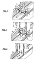
- FIGS. 6, 7 and 8 are different stages in the assembly of a post 16 with its two ends each shown on a frame support 15 and 17 made of plastic, as in the manufacturing process of a window frame 25 (see. Fig. 17 ) are present on a frame welding machine 18.
- FIG. 6 a side view of the post 16 with the two associated frame rails 15 and 17 after inserting the various frame parts in the frame welding machine
- Fig. 7 a longitudinal section through the arrangement Fig. 6 but in an already partially assembled intermediate stage
- Fig. 8 again a side view of the arrangement, but this time in final assembly state.
- a post connector 1 is already fastened by screws 11 to each of the two frame supports 15 and 17 shown.
- the post 16 is arranged in the frame welding machine so that the respective mold projection 4 of the associated post connector 1 protrudes to a certain extent already in the facing hollow profile of the post 16, in such a way that there the guide pin 12 already on the two flat sliding surfaces. 8 this shape projection 4 is applied.
- the frame welding machine is in this case in the extended position, d. H. the mounted on the frame welding frame profiles are spent in a remote position. Since in this position the mold projection 4 of each post connector 1 already protrudes into the hollow profile of the post 16 to be connected, it is ensured that the post 16 on the ends of the mold protrusions 4 already engaging at its ends in him under the support of his local guide pin 12 on the facing Sliding surfaces 8 is securely held and can not fall down.
- the sectional view of the Fig. 7 now shows an intermediate position during the assembly process, in which the distance between the two frame members 15 and 17 already against the position Fig. 6 reduced, but the final assembly position has not yet been reached.
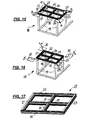
- a frame welding machine 18 which has a machine frame 19 which is provided at its upper end with four movable welding mirrors 20, each of which serves in the subsequent welding of a frame 25 for welding to a frame corner.
- Each welding mirror 20 is mounted so that it is at a desired miter angle, which is 45 ° in the illustrated embodiment, the individual mitred precut frame sections 15, 21, 22, 23 (see. Fig. 17 ) are heated at their abutting ends for welding.
- the welding mirrors 20 in the direction of arrow a (see. Fig. 15 ) between the frame corners to heat the facing end surfaces of the frame profiles for welding, after which the welding mirror 20 in the opposite direction a ' (see. Fig. 16 ) are driven outwards again.
- a frame profile 21 is first arranged on the machine frame 19 of the welding machine 18, as this Fig. 9 shows.
- a frame carrier is arranged centrally as a post 17, after which, approximately in the middle of the frame profiles 15 and 22, a further post 24, oriented perpendicular to these, is inserted (FIG. Fig. 12 ).
- Fig. 13 is illustrated, is still between the frame members 15 and 17, a post 16, aligned with the post 24, placed.
- the welding mirror 20 retracted in the feed direction (arrows a ) between the ends of the frame profiles 15, 21, 22 and 23, then this by the frame welding machine 18 moves toward each other so that their end faces abut against the welding mirror 20, after which the welding mirror 20 are heated and effect a corresponding heating of the voltage applied to them end surfaces of the frame profiles 15, 21, 22 and 23.
Abstract
Bei einer Verbindungsanordnung zum Befestigen eines Hohlprofil-Pfostens (16) mit einem Rahmenträger (15) und einem an diesem befestigten Pfostenverbinder (1), der eine Grundplatte (2) mit seitlich senkrecht hochlaufenden Seitenwänden (3) aufweist, deren jede eine Aufnahmevertiefung (6) mit einem oberen offenen Einlaßabschnitt (7) aufweist, und durch den Endbereich des Pfostens (16) ein Führungsbolzen (13) angebracht ist, dessen axiale Endabschnitte seitlich vom Pfosten (16) nach außen überstehen sowie am Montageende in den Aufnahmevertiefungen (6) der Seitenwände (3) aufgenommen sind, ist der Pfosten (16) formschlüssig auf den Pfostenverbinder (1) aufsteckbar, wobei letzterer zwischen beiden Seitenwänden (3) einen von der Grundplatte (2) vorstehenden Formvorsprung (4) mit einer Vorderseite umfaßt, an der mindestens eine ebene Gleitfläche (8) angebracht ist, deren Aufspannebene tangential zum Einlaßabschnitt (7) der Aufnahmevertiefungen (6) liegt. Der Formvorsprung (4) weist an jeder seiner beiden Seiten eine von der Grundplatte (2) aus verlaufende Führungsfläche (9) auf, auf welcher der Endbereich des Hohlprofils des Pfostens (16) gleitend geführt ist, wobei der Führungsbolzen (13) bei der Montage an der mindestens einen Gleitfläche (8) des Formvorsprungs (4) gleitend anliegt.In a connection arrangement for fixing a hollow-profile post (16) with a frame support (15) and attached thereto post connector (1) having a base plate (2) with laterally vertically rising side walls (3), each having a receiving recess (6 ) having an upper open inlet portion (7), and through the end portion of the post (16) a guide pin (13) is mounted, the axial end portions laterally projecting from the post (16) to the outside and at the mounting end in the receiving recesses (6) Side walls (3) are accommodated, the post (16) is positively plugged onto the post connector (1), the latter between the two side walls (3) from the base plate (2) protruding mold projection (4) having a front, on the at least a flat sliding surface (8) is mounted, the clamping plane is tangent to the inlet portion (7) of the receiving recesses (6). The mold projection (4) has, on each of its two sides, a guide surface (9) extending from the base plate (2), on which the end portion of the hollow profile of the post (16) is slidably guided, wherein the guide pin (13) during assembly on the at least one sliding surface (8) of the mold projection (4) slidably abuts.
Description
Die Erfindung bezieht sich auf eine Verbindungsanordnung zum Befestigen eines Pfostens an einem Rahmenträger eines Fensters, einer Türe oder dgl. aus Kunststoff, wobei der Pfosten ein Hohlprofil aufweist, das zur Montage mit einem am Rahmenträger angebrachten Pfostenverbinder befestigbar ist, der eine Grundplatte mit an beiden Seiten senkrecht hochlaufenden Seitenwänden aufweist, in deren jeder an ihrer frei von der Grundplatte vorstehenden Abschlußkante eine Aufnahmevertiefung mit einem zur Abschlußkante hin offenen Einlaßquerschnitt ausgebildet ist und beide Aufnahmevertiefungen zueinander ausgerichtet sind, wobei senkrecht zu den Seitenwänden durch den Endbereich des Hohlprofils des Pfostens ein Führungsbolzen verläuft, dessen beide axialen Endbereiche seitlich vom Pfosten nach außen hin überstehen sowie am Ende der Montage in den beiden Aufnahmevertiefungen der Seitenwände aufgenommen sind.The invention relates to a connection arrangement for attaching a post to a frame support of a window, a door or the like. Plastic, wherein the post has a hollow profile which can be fastened for mounting with a frame support mounted on the post connector having a base plate with at both Pages vertically uprising side walls, in each of which a receiving recess is formed at its free from the base plate projecting end edge with an opening edge open towards the inlet and both receiving recesses are aligned with each other, perpendicular to the side walls through the end portion of the hollow profile of the post, a guide pin extends whose two axial end portions laterally project laterally from the post and are received at the end of the assembly in the two receiving recesses of the side walls.
Im Rahmen dieses Textes soll der Ausdruck "Pfosten" sowohl Pfosten, als auch Sprossen bezeichnen, und der Begriff "Rahmenträger" wird als übergeordnete Bezeichnung für die Rahmenprofile, die den Außenumfang eines Rahmens festlegen, sowie für Pfosten und Sprossen innerhalb der Aufspannfläche des Rahmens verwendet.In the context of this text, the term "jambs" is intended to designate both jambs and rungs, and the term "frame girders" is used as a generic term for the frame profiles defining the outer circumference of a frame as well as posts and rungs within the clamping surface of the frame ,
Aus den
Diese bekannten Verbindungsanordnungen mit jeweils einem mehrteiligen Pfostenverbinder sind jedoch zur Verwendung bei der Herstellung von Kunststoffrahmen für Fenster oder Türen mittels einer automatisierten Rahmenschweißmaschine nicht geeignet, da jeweils die Vielzahl und die Komplexität der beim Zusammenbau vorzunehmenden Einzelmaßnahmen es erfordert, zunächst auf der Schweißmaschine den Hauptrahmen herzustellen, um anschließend in einem getrennten Schritt dann die gewünschten Pfosten am Rahmen anzubringen und zu montieren.However, these known connection arrangements, each with a multi-part post connector, are for use in the manufacture of plastic frames for windows or doors not suitable by means of an automated frame welding machine, since in each case the variety and complexity of the individual measures to be taken during assembly, it is necessary first to produce the main frame on the welding machine in order to subsequently attach and mount the desired posts to the frame in a separate step.
Eine Verbindungsanordnung der eingangs genannten Art wird in der
Ausgehend hiervon liegt der Erfindung die Aufgabe zugrunde, eine Verbindungsanordnung der eingangs genannten Art so auszugestalten, daß sie die Montage und Befestigung von Pfosten am Hauptrahmen gleichzeitig mit dessen Herstellung auf einer üblichen Rahmenschweißmaschine gestattet, sowie einen zur Verwendung in einer solchen Verbindungsanordnung geeigneten Pfostenverbinder vorzuschlagen.Proceeding from this, the invention has the object, a connection assembly of the type mentioned in such a way that it allows the mounting and attachment of posts on the main frame at the same time with its production on a conventional frame welding machine, and to propose a suitable for use in such a connector assembly post connector.
Die erfindungsgemäße Verbindungsanordnung wird bei einer Verbindungsanordnung der eingangs genannten Art dadurch erreicht, daß der Pfostenverbinder bei der Montage formschlüssig in das Hohlprofil des Pfostens einführbar ist, der Pfostenverbinder zwischen seinen beiden Seitenwänden einen von der Grundplatte vorragenden, sich über die Höhe der Seitenwände hinaus erstreckenden Formvorsprung umfaßt, welcher eine Vorderseite aufweist, an der er über seine Höhe hinweg mit mindestens einer ebenen Gleitfläche versehen ist, deren Aufspannebene senkrecht zu den Seitenwänden und tangential zum Einlaßabschnitt der beiden Aufnahmevertiefungen liegt, wobei ferner der Formvorsprung an jeder seiner beiden jeweils einer Seitenwand zugewandten Seiten mit einer von der Grundplatte aus mindestens über einen Teilbereich seiner Höhenerstreckung verlaufenden Führungsfläche versehen ist, auf der bei der Montage der Endbereich der Innenfläche der zugewandten Seitenwand des Hohlprofils des Pfostens gleitend geführt ist, und wobei der Führungsbolzen im Endbereich des Hohlprofils des Pfostens so angeordnet ist, daß er bei der Montage an der mindestens einen Gleitfläche des Formvorsprungs gleitend anliegt.The connection arrangement according to the invention is achieved in a connection arrangement of the type mentioned above in that the post connector during assembly is positively inserted into the hollow profile of the post, the post connector between its two side walls projecting from the base plate, extending beyond the height of the side walls also protrusion which has a front surface at which it is provided over its height with at least one flat sliding surface whose clamping plane is perpendicular to the side walls and tangential to the inlet portion of the two receiving recesses, further wherein the shaping projection on each of its two each side wall facing sides is provided with an extending from the base plate at least over a portion of its height extension guide surface on which during assembly of the end portion of the inner surface of the facing side wall of the hollow profile of the P fostens is slidably guided, and wherein the guide pin is arranged in the end region of the hollow profile of the post so that it is slidably mounted on the at least one sliding surface of the mold projection during assembly.
Bei Verwendung der erfindungsgemäßen Verbindungsanordnung findet bei der Montage zunächst ein formschlüssiges Aufstecken des Pfostens auf den Pfostenverbinder statt, was durch den von der Grundplatte des Pfostenverbinders im Hinblick auf den Pfosten vorspringenden Formvorsprung gewährleistet werden kann. Bei diesem formschlüssigen Zusammenfügen liegt der im Endbereich des Pfostens durch dessen Hohlprofil hindurch angebrachte Führungsbolzen während des Montagevorgangs entlang mindestens einer an der Vorderseite des Formvorsprungs angebrachten ebenen Gleitfläche, die sich in Höhenrichtung des Formvorsprungs erstreckt, an und wird dort gleitend geführt. Dabei ist diese ebene Gleitfläche so angeordnet, daß sie auch tangential zum Einlaßabschnitt der beiden Aufnahmevertiefungen an den Seitenwänden ausgerichtet ist, so daß beim Aufstecken des Pfostens auf den Pfostenverbinder der Führungsbolzen, im Endzustand der Montage, direkt in die Aufnahmevertiefungen der Seitenwände eingeleitet und dort aufgenommen wird. Damit wird mit der erfindungsgemäßen Verbindungsanordnung bei der Montage des Pfostens am Pfostenverbinder eine präzise Führung des Pfostens relativ zum Pfostenverbinder während des ganzen Montagevorgangs gewährleistet und dabei auch sichergestellt, daß infolge des Einlaufs des Führungszapfens in die Aufnahmevertiefungen an den Seitenwänden des Pfostenverbinders am Ende der Montage auch ein ganz präziser Sitz des Pfostens relativ zum Pfostenverbinder eintritt.When using the connection arrangement according to the invention initially takes place during assembly a positive attachment of the post on the post connector, which can be ensured by the projecting from the base plate of the post connector with respect to the post molding projection. In this form-locking joining, the latter lies in the end region of the post through its hollow profile mounted guide pins during the mounting operation along at least one attached to the front of the mold projection flat sliding surface which extends in the height direction of the molding projection, and is slidably guided there. In this case, this flat sliding surface is arranged so that it is also aligned tangentially to the inlet portion of the two receiving recesses on the side walls, so that when plugging the post on the post connector of the guide pin, introduced in the final state of assembly, directly into the receiving recesses of the side walls and received there becomes. Thus, with the connection assembly according to the invention in the assembly of the post to the post connector ensures a precise management of the post relative to the post connector during the entire assembly process, while also ensuring that due to the inlet of the guide pin in the receiving recesses on the side walls of the post connector at the end of assembly also a very precise fit of the post relative to the post connector occurs.
Die Bewegungen der Schweißmaschinen betragen bei einer Rahmenherstellung, abweichend vom Sollmaß, etwa 40 mm. Wird bei einer solchen Herstellung die erfindungsgemäße Verbindungsanordnung für die Befestigung eines Pfostens an einem zugeordneten Rahmenträger eingesetzt, dann ist dabei der Formvorsprung des an dem Rahmenträger bereits befestigten Pfostenverbinder so ausgelegt, daß er schon im eingelegten und auch im auseinandergefahrenen Zustand der verschiedenen Pfosten und Rahmenteile in den Hohlquerschnitt des zugeordneten Pfostens hineinragt, wobei auch schon der Schaft des Führungsbolzens an der mindestens einen ebenen Gleitfläche des Formvorsprungs anliegt. Dies hat zur Folge, daß der Pfosten, der im eingelegten Zustand an seinen beiden Enden an dem dort jeweils vorliegenden Rahmenträger jeweils über einen Pfostenverbinder zu befestigen ist, auch schon in dem Zustand, bei dem die Schweißmaschine sich in ihrem auseinandergefahrenen Zustand befindet, an seinen beiden Enden jeweils von dem dort in seinen Hohlquerschnitt hineinragenden Formvorsprung des jeweiligen Pfostenverbinders gehalten wird und nicht mehr herunterfallen kann. Die Schweißmaschine kann somit problemfrei die verschiedenen Rahmenteile auseinanderfahren und schließen, wobei beim Schließen die Endabschnitte der Führungsbolzen an den Endbereichen des Pfostens jeweils in die Aufnahmevertiefungen der Seitenwände des jeweiligen Pfostenverbinders präzise und formschlüssig in ihre Montage-Endposition eingeschoben werden.The movements of the welding machines are at a frame production, deviating from the nominal size, about 40 mm. If the connection arrangement according to the invention for the attachment of a post to an associated frame support is used in such a production, then the shape projection of the already fixed to the frame support post connector is designed so that it already in the inserted and disassembled state of the various posts and frame parts in protrudes the hollow cross-section of the associated post, whereby even the shank of the guide pin rests against the at least one flat sliding surface of the molding projection. This has the consequence that the post, which is to be fixed in the inserted state at its two ends to the respectively present there frame support in each case via a post connector, even in the state in which the welding machine is in its disassembled state, to his both ends of each of which is held in its hollow cross-section projecting mold projection of the respective post connector and can not fall off. The welding machine can thus move apart and close the various frame parts problem-free, wherein when closing the end portions of the guide pins at the end portions of the post are respectively inserted into the receiving recesses of the side walls of the respective post connector precisely and positively in their final assembly position.
Damit ist bei der Verwendung der erfindungsgemäßen Verbindungsanordnung auch eine Befestigung zwischen Pfosten und Rahmenträger auf einer herkömmlichen Rahmenschweißmaschine gleichzeitig mit der Herstellung des Hauptrahmens möglich, was nicht nur eine besonders rasche, sondern auch kostengünstige Herstellung des gesamten Rahmens auf der Maschine zuläßt.Thus, when using the connection arrangement according to the invention also an attachment between posts and frame support on a conventional frame welding machine simultaneously with the production of the main frame possible, which allows not only a particularly rapid, but also cost-effective production of the entire frame on the machine.
Der erfindungsgemäße Pfostenverbinder zur Verwendung bei einer erfindungsgemäßen Verbindungsanordnung weist eine Grundplatte mit an beiden Seiten senkrecht hochlaufenden Seitenwänden auf, in deren jeder an ihrer frei von der Grundplatte vorstehenden Anschlußkante eine Aufnahmevertiefung mit einem zur Abschlußkante hin offenen Einlaßabschnitt ausgebildet ist, wobei beide Aufnahmevertiefungen zueinander ausgerichtet sind. Erfindungsgemäß ist dabei zwischen beiden Seitenwänden ein von der Grundplatte vorstehender, sich über die Höhe der Seitenwände hinaus erstreckender Formvorsprung vorgesehen, der eine Vorderseite aufweist, an der über seine Höhe hinweg mindestens eine ebene Gleitfläche angebracht ist, deren Aufspannebene senkrecht zu den Seitenwänden und tangential zum Einlaßabschnitt der beiden Aufnahmevertiefungen liegt, wobei ferner der Formvorsprung an jeder seiner beiden jeweils einer Seitenwand zugewandten Seiten mit einer von der Grundplatte aus mindestens über einen Teilbereich seiner Höhenerstreckung verlaufenden ebenen Führungsfläche versehen ist.The post connector according to the invention for use in a connecting arrangement according to the invention has a base plate with vertically upwardly extending side walls on each side, in each of which a receiving recess is formed at its freely projecting from the base plate connecting edge with an opening edge open towards the end edge, wherein both receiving recesses are aligned , According to the invention, a projection protruding from the base plate and extending beyond the height of the side walls is provided between the two side walls, which has a front face over which at least one flat sliding surface is mounted over its height, the clamping plane being perpendicular to the side walls and tangent to the side walls In addition, the molding projection is provided on each of its two sides facing each side wall with a planar guide surface extending from the base plate over at least a portion of its height extension.
Eine besonders günstige Ausgestaltung der Erfindung besteht darin, daß am Formvorsprung nicht nur eine, sondern zwei zueinander parallele, in einer gemeinsamen Aufspannfläche liegende ebene Gleitflächen angebracht sind, wodurch sich besonders günstige Verhältnisse bei der formschlüssigen Führung des Pfostens auf dem Formvorsprung des Pfostenverbinders ergeben.A particularly advantageous embodiment of the invention is that the shape projection not only one, but two mutually parallel, mounted in a common clamping surface flat sliding surfaces are mounted, resulting in particularly favorable conditions in the positive guidance of the post on the molding projection of the post connector.
Es ist ferner besonders vorteilhaft, wenn die beiden Aufnahmevertiefungen in den Seitenwänden des Pfostenverbinders einen identischen Querschnitt aufweisen, wobei, erneut vorzugsweise, jede Aufnahmevertiefung im mittleren Bereich der zugeordneten Seitenwand ausgebildet ist.It is also particularly advantageous if the two receiving recesses in the side walls of the post connector have an identical cross section, wherein, again preferably, each receiving recess is formed in the central region of the associated side wall.
Bevorzugt wird außerdem die obere Abschlußkante jeder Seitenwand an ihrer dem Formvorsprung zugewandten Seite mit einer zur Grundplatte hin geneigten Abschrägung versehen, so daß beim Aufschieben des Pfostens auf den Formvorsprung eine günstige Einleitung der seitlichen Endkanten des Pfostens bei Erreichen der Abschlußkanten der beiden Seitenwände in Richtung auf die Führungsflächen am Formvorsprung hin gewährleistet ist.Preferably also, the upper end edge of each side wall is provided on its side facing the mold protrusion with a bevel inclined to the base plate, so that when pushing the post on the mold projection a favorable introduction of the lateral end edges of the post upon reaching the end edges of the two side walls in the direction the guide surfaces is ensured at the molding projection out.
Bei der Erfindung kann jede Aufnahmevertiefung in jeder geeigneten Form ausgeführt werden, wobei jedoch als ganz besonders bevorzugt ein im wesentlichen kreisförmiger Öffnungsquerschnitt vorgesehen wird, da in ihm der in der Regel auch kreisförmige Schaft des Führungsbolzens in seinem Montage-Endzustand optimal gehalten wird.In the invention, each receiving recess can be made in any suitable form, but as a very particularly preferred a substantially circular opening cross-section is provided, since in him the usually circular shaft of the guide pin is optimally maintained in its final assembly state.
Eine weiter bevorzugte Ausgestaltung der erfindungsgemäßen Verbindungsanordnung besteht auch darin, daß der Führungsbolzen an seinen seitlich vom Pfosten vorstehenden Endabschnitten an deren Enden jeweils einen radial vergrößerten Bolzenkopf aufweist. Dadurch wird im montierten Endzustand auch eine axiale Festlegung des Führungsbolzens und damit des entsprechenden Endbereiches des Pfostens am Pfostenverbinder erreicht.A further preferred embodiment of the connection arrangement according to the invention also consists in that the guide pin has at its ends projecting laterally from the post end portions at their ends in each case a radially enlarged bolt head. As a result, an axial fixing of the guide pin and thus of the corresponding end region of the post on the post connector is achieved in the assembled final state.
In einer vorteilhaften Ausgestaltung der erfindungsgemäßen Verbindungsanordnung wird der Führungsbolzen so ausgebildet, daß er aus zwei Teilen besteht, deren eines ein mit einem Innengewinde versehener Schaftbolzen und deren anderes ein in diesen von der anderen Seite her eingeschraubter Schraubbolzen ist, was ein besonders einfaches Montieren des Führungsbolzens am Pfosten gestattet.In an advantageous embodiment of the connection arrangement according to the invention, the guide pin is formed so that it consists of two parts, one of which is provided with an internal threaded shaft pin and the other is a screwed into this from the other side screw, which is a particularly simple mounting of the guide pin allowed at the post.
Besonders bevorzugt ist es auch, wenn bei der Erfindung jede Aufnahmevertiefung, in einem Schnitt in axialer Richtung gesehen, eine sich axial nach der Außenseite der Seitenwand hin erweiternde Form aufweist, die mit einer entsprechenden komplementären Formgebung des Bolzenkopfes zusammenwirken kann, um diesen während der Montage beim Einlaufen in die betreffende Aufnahmevertiefung zu zentrieren und in der Montageendstellung auch eine besonders sichere Fixierung zu erreichen. Dabei wird vorteilhafterweise für die sich axial nach außen erweiternde Form jeder Aufnahmevertiefung eine kegelabschnittförmige Ausgestaltung vorgesehen.It is also particularly preferred if in the invention, each receiving recess, seen in a section in the axial direction, an axially towards the outside of the side wall widening shape, which can cooperate with a corresponding complementary shape of the bolt head to this during assembly to center when entering the relevant receiving recess and to achieve a particularly secure fixation in the final assembly position. In this case, a cone-shaped configuration is advantageously provided for the axially outwardly widening shape of each receiving recess.
Eine weitere vorteilhafte Ausgestaltung der Erfindung besteht auch darin, daß jede ebene Gleitfläche des Formvorsprungs an ihrem von der Grundplatte abliegenden Endbereich mit einem von ihr vorspringenden Anschlag zur Begrenzung einer Bewegung des Führungsbolzens in Richtung von der Grundplatte weg versehen ist. Damit kann erreicht werden, daß im in die Schweißmaschine eingelegten Zustand für den Fall, daß dort mit vertikalen Bewegungen gearbeitet wird, im offenen bzw. geöffneten Zustand der Schweißmaschine auch in vertikaler Richtung ein eingelegter Pfosten nicht mehr abfallen kann.A further advantageous embodiment of the invention consists in the fact that each flat sliding surface of the mold projection is provided at its end remote from the base end portion with a protruding from her stop to limit movement of the guide pin in the direction of the base plate away. This can be achieved that in the inserted into the welding machine state in the event that there is worked with vertical movements, in the open or open state of the welding machine in the vertical direction an inserted post can not fall off.
Auch wenn die erfindungsgemäße Verbindungsanordnung sich aufgrund ihrer Vorzüge in besonderer Weise zur Verwendung bei der Herstellung von Fenster- oder Türrahmen aus Kunststoff auf einer Rahmenschweißmaschine anwenden läßt, ist es natürlich gleichermaßen auch möglich, diese Verbindungsanordnung bei einer Rahmenherstellung vorzusehen, bei der auf den Einsatz einer Rahmenschweißmaschine verzichtet wird.Although the connection arrangement according to the invention can be used in a special way for use in the production of plastic window or door frames on a frame welding machine, it is of course equally possible to provide this connection arrangement in a frame manufacturing, in the use of a Frame welding machine is omitted.
Die erfindungsgemäße Verbindungsanordnung ist im Vergleich zu bekannten Verbindungsanordnungen relativ einfach in ihrem Aufbau, leicht handhabbar und auch unkompliziert beim Einsatz an einer Rahmenschweißmaschine. Sie ermöglicht es erstmals, in einem Arbeitsgang auf einer Rahmenschweißmaschine sowohl den Hauptrahmen, wie auch an diesem angebrachte Pfosten herzustellen und zu montieren.Compared with known connection arrangements, the connection arrangement according to the invention is relatively simple in construction, easy to handle and also uncomplicated when used on a frame welding machine. It allows for the first time, in one operation on a frame welding machine both the main frame, as well as attached to this post and assemble.
Die Erfindung wird nachfolgend anhand der Zeichnungen im Prinzip beispielshalber noch näher erläutert. Es zeigen:
- Fig. 1
- einen erfindungsgemäßen Pfostenverbinder in einer perspektivischen Schrägdarstellung, wobei rein prinzipiell die Zuordnung zu einem Führungsbolzen eines anzuschließenden Pfostens (aber im isolierten Zustand des Führungsbolzens) gezeigt ist;
- Fig. 2
- einen Schnitt längs Schnittebene II-II in
Fig. 1 ; - Fig. 3
- eine vergrößerte perspektivische Detaildarstellung eines an einem Rahmenträger befestigten erfindungsgemäßen Pfostenverbinders;
- Fig. 4
- den Pfostenverbinder aus
Fig. 3 , jedoch zu Beginn des Aufsetzens eines anzuschließenden Pfostens; - Fig. 5
- die Darstellung aus
Fig. 4 , jedoch mit vollständig aufgeschobenem Pfosten; - Fig. 6
- in einer seitlichen Ansicht zwei Rahmenträger mit jeweils einem dazwischen angebrachten Pfosten im auseinandergefahrenen Zustand der Schweißmaschine;
- Fig. 7
- die Darstellung aus
Fig. 6 , jedoch im Längsschnitt, wobei die beiden Rahmenträger sich in einer bereits etwas aufeinanderzu bewegten Zwischenstellung befinden; - Fig. 8
- eine Seitenansicht entsprechend der aus
Fig. 6 , jedoch im zusammengefahrenen Zustand der Schweißmaschine, wobei der Pfosten an seinen Enden mit den beiden anzuschließenden Rahmenträgern endmontiert ist; - die Fig. 9 bis 16
- in einer prinzipiellen Darstellung die Herstellung eines Kunststoff-Fensterrahmens auf einer Rahmenschweißmaschine in verschiedenen Stadien, wobei
Fig. 9 das Anfangsstadium nach Einlegung eines ersten Rahmenprofiles undFig. 16 das Endstadium nach erfolgter Rahmenverschweißung und anschließendem Zusammenpressen der Rahmenprofile darstellt und dieFig. 10 bis 15 Zwischenstadien illustrieren, und - Fig. 17
- in einer perspektivischen Prinzipdarstellung den fertiggestellten Fensterrahmen.
- Fig. 1
- a post connector according to the invention in a perspective oblique view, which is shown purely in principle the assignment to a guide pin of a post to be connected (but in the isolated state of the guide pin);
- Fig. 2
- a section along section plane II-II in
Fig. 1 ; - Fig. 3
- an enlarged detail perspective view of a mounted on a frame support inventive post connector;
- Fig. 4
- out the post connector
Fig. 3 but at the beginning of placing a post to be connected; - Fig. 5
- the presentation
Fig. 4 but with the post completely pushed away; - Fig. 6
- in a side view, two frame beams, each with a post mounted therebetween in the disassembled state of the welding machine;
- Fig. 7
- the presentation
Fig. 6 but in longitudinal section, wherein the two frame members are in an intermediate position already slightly moved towards each other; - Fig. 8
- a side view according to the
Fig. 6 but in the contracted state of the welding machine, wherein the post is mounted at its ends with the two frame members to be connected; - FIGS. 9 to 16
- in a schematic representation of the production of a plastic window frame on a frame welding machine in various stages, wherein
Fig. 9 the initial stage after filing a first frame profile andFig. 16 represents the final stage after frame welding and subsequent compression of the frame profiles and the10 to 15 Illustrate intermediate stages, and - Fig. 17
- in a perspective schematic representation of the completed window frame.
In allen Figurendarstellungen sind ganz grundsätzlich gleiche Teile durchgängig mit gleichen Bezugszeichen versehen.In all figure representations are basically the same parts consistently provided with the same reference numerals.
Zunächst sei auf die Darstellung der
Der Pfostenverbinder 1 weist eine Grundplatte 2 auf (vgl.
Ferner läuft von dem hinteren (in
Dieser Formvorsprung 4 dient (worauf im folgenden noch näher eingegangen werden wird) dem Zweck, daß er beim Zusammenbau des Pfostenverbinders 1 mit einem anzuschließenden Pfosten, dessen Profil seinerseits als Kunststoff-Hohlprofil ausgebildet ist, in geeigneter Weise formschlüssig in das Hohlprofil des Pfostens bei der Montage eingeschoben werden kann, bis der Pfosten am Montageende fest auf dem Pfostenverbinder 1 sitzt.This form of
Wie die
Wie insbesondere gut aus
Der Formvorsprung 4 ist an seiner der Aufnahmevertiefung 6 zugewandten Vorderseite mit zwei senkrecht nach oben laufenden, zueinander parallel angeordneten ebenen Gleitflächen 8 versehen, wie dies am besten aus der Darstellung der
Wie ebenfalls aus
Die Aufnahmevertiefungen 6 sind so ausgeführt, daß sie sich, in einem axialen Schnitt, jeweils zur Außenseite der betreffenden Seitenwand 3 hin im Querschnitt erweitern, wobei hierfür bevorzugt eine kegelabschnittförmige Erweiterung vorgesehen wird, wie sie in den Figuren nur ganz prinzipiell angedeutet ist.The receiving recesses 6 are designed so that they expand, in an axial section, in each case to the outside of the
Weiterhin ist am Formvorsprung 4, der auch als "Dom" bezeichnet wird, an dessen beiden jeweils einer Seitenwand 3 zugewandten Seiten eine Führungsfläche 9 ausgebildet, die vom unteren, der Grundplatte 2 zugewandten Ende des Formvorsprungs 4 aus verläuft und sich zumindest über einen Teil seiner Gesamthöhe erstreckt.Furthermore, on the
Diese beiden seitlichen Führungsflächen 9 am Formvorsprung 4 dienen dazu, beim Einführen des Formvorsprungs 4 in das Hohlprofil eines anzuschließenden Pfostens den Endbereich des letzteren seitlich zu führen, so daß die Seitenwände des Pfostens bei der Montage in einen Zwischenraum zwischen der jeweiligen Führungsfläche 9 und der ihr zugewandten Innenseite der zugeordneten Seitenwand 3 des Pfostenverbinders 1 seitlich formschlüssig geführt einlaufen.These two lateral guide surfaces 9 on the
Am oberen, der Grundplatte 2 abgewandten Ende jeder ebenen Gleitfläche 8 ist an dieser, wie insbesondere aus der Schnittdarstellung der
Die Seitenwände 3 sind ferner an ihrer oberen Abschlußkante 5 auf ihrer der jeweils anderen Seitenwand 3 zugewandten Seite mit einer zur Grundplatte 2 hin geneigten Abschrägung 14 versehen, die bei der Montage einen guten Einlauf der zugeordneten Seitenfläche des anzuschließenden Pfostens an der Innenseite der jeweiligen Seitenwand 3 gewährleistet.The
Zur Herstellung einer Verbindung zwischen dem Ende des Hohlquerschnitts eines Pfostens und einer Rahmenleiste wird zunächst, wie dies
Nach dem Aufsetzen auf den Rahmenträger 15 wird der Pfostenverbinder 1 über mehrere Schrauben 11 (vgl.
Anschließend wird ein Pfosten 16, der ein Hohlprofil aufweist, von der in
Der Pfosten 16 ist an seinem unteren Endbereich mit einem parallel zur Längsrichtung des Rahmenträgers 15 durch sein Hohlprofil hindurch verlaufenden Führungsbolzen 12 versehen, der an seinen Endabschnitten über die beiden einander gegenüberliegenden Seitenwände des Pfostens 16 vorsteht und dort jeweils in einen im Durchmesser vergrößerten Bolzenkopf 13 mündet.The
In der zeichnerischen Darstellung der
Der Führungsbolzen 12 ist dabei am unteren Endbereich des anzuschließenden Pfostens 16 in einer solchen Lage angebracht, daß er in der in
Die Lage des Führungsbolzens 12 am Pfosten 16 ist zudem so, daß er während der Montage an den ebenen Gleitflächen 8 des Formvorsprungs 4 anliegt und entlang derselben gleitet. Infolge der Ausrichtung der Aufspannebene der ebenen Gleitflächen 8 tangential zum Einlaufabschnitt 7 der Aufnahmenvertiefung 6 wird der Führungsbolzen 2 am Ende seines Herabgleitens entlang der Gleitflächen 8 in die Aufnahmevertiefung 6 hinein geführt, so daß er beim Ende des Montagevorgangs mit seinen seitlich vorstehenden Endabschnitten in den Aufnahmevertiefungen 6 aufgenommen ist und seitlich so auch über diese vorsteht, daß der jeweilige Bolzenkopf 13 an der Außenseite der zugeordneten Aufnahmevertiefung 6 liegt, wie dies
Der Führungsbolzen 12 besteht aus zwei Teilen, einem ersten Teil in Form eines Schaftbolzens mit einem Innengewinde im Schaft, und einem zweiten Teil in Form eines Schraubbolzens mit Außengewinde, der in den Schaftbolzen eingeschraubt ist. Prinzipiell könnte der Führungsbolzen 12 aber auch z. B. aus einem Schaftniet bestehen, an dem nach seinem Anbringen am Pfosten beidseits je ein Kopf angeformt wird.The
Die Anschläge 10 am jeweils der Grundplatte 2 abgewandten Ende der beiden ebenen Gleitflächen 8 verhindern, daß der Bolzen 12 bei einem Hochlaufen in Gegenrichtung über das obere Ende des Formvorsprungs 4 hinauslaufen und außer Eingriff mit den beiden ebenen Gleitflächen 8 gelangen könnte, worauf weiter unten noch einmal einzugehen sein wird.The stops 10 on each of the
In den
Dabei zeigt die
Wie aus den Figuren erkennbar, ist an jedem der beiden gezeigten Rahmenträger 15 und 17 jeweils bereits ein Pfostenverbinder 1 über Schrauben 11 befestigt.As can be seen from the figures, a post connector 1 is already fastened by
Dabei ist der Pfosten 16 in der Rahmenschweißmaschine so angeordnet, daß der jeweilige Formvorsprung 4 des zugeordneten Pfostenverbinders 1 zu einem gewissen Teil schon in das zugewandte Hohlprofil des Pfostens 16 hineinragt, und zwar derart, daß dort der Führungsbolzen 12 bereits auf den beiden ebenen Gleitflächen 8 dieses Formvorsprungs 4 anliegt.In this case, the
Die Rahmenschweißmaschine befindet sich hierbei in der ausgefahrenen Stellung, d. h. die an der Rahmenschweißmaschine angebrachten Rahmenprofile sind in eine voneinander entfernte Stellung verbracht. Da auch in dieser Stellung der Formvorsprung 4 jedes Pfostenverbinders 1 bereits in das Hohlprofil des anzuschließenden Pfostens 16 hineinragt, ist sichergestellt, daß der Pfosten 16 über die an seinen Enden in ihn bereits eingreifenden Endbereiche der Formvorsprünge 4 unter Auflage seiner dortigen Führungsbolzen 12 auf die zugewandten Gleitflächen 8 sicher gehalten ist und nicht nach unten herausfallen kann.The frame welding machine is in this case in the extended position, d. H. the mounted on the frame welding frame profiles are spent in a remote position. Since in this position the
Infolge des Vorhandenseins der Anschläge 10 an den freien Enden der ebenen Gleitflächen 8 (vgl.
Die Schnittdarstellung der
Diese Montage-Endstellung ist dann in
Aus den Figuren, insbesondere den
In den
Jeder Schweißspiegel 20 ist dabei so angebracht, daß er unter einem gewünschten Gehrungswinkel, der im dargestellten Ausführungsbeispiel 45° beträgt, die einzelnen auf Gehrung vorgeschnittenen Rahmenprofile 15, 21, 22, 23 (vgl.
Dabei sind die Schweißspiegel 20 in Pfeilrichtung a (vgl.
Zur Herstellung eines Fensterrahmens 25 (vgl.
Anschließend werden an den beiden Enden dieses Rahmenprofils 21 senkrecht zu diesem zwei weitere zueinander parallele Rahmenprofile 15, 22 angebracht, was in
In einem nächsten, in
In einem weiteren Schritt, der in
Anschließend wird ein letztes Rahmenprofil 23 aus Kunststoff in der Rahmenschweißmaschine 18 angebracht, wie dies
Bei allen Einlegevorgängen befinden sich die Schweißspiegel 20 in ihrer ausgefahrenen Position, wie dies die
Hiernach werden, wie aus
Anschließend werden, wie in
Zur Befestigung zwischen den Rahmenprofilen 15, 21, 22 und 23 und den an diese angeschlossenen Pfosten 16, 17 und 24 sowie zur Verbindung der letzteren untereinander werden an den Verbindungsstellen Pfostenverbinder entsprechend dem Pfostenverbinder 1 aus den
Dabei ist zu beachten, daß beim Einlegen der verschiedenen Rahmenträger (Rahmenleisten und Pfosten) in die Schweißmaschine 18, wie dies in den
Claims (13)
Applications Claiming Priority (1)
| Application Number | Priority Date | Filing Date | Title |
|---|---|---|---|
| DE102013223968.8A DE102013223968B4 (en) | 2013-11-22 | 2013-11-22 | Connecting arrangement for attaching a post to a frame support of a window, a door or the like. Made of plastic |
Publications (1)
| Publication Number | Publication Date |
|---|---|
| EP2876242A1 true EP2876242A1 (en) | 2015-05-27 |
Family
ID=51868769
Family Applications (1)
| Application Number | Title | Priority Date | Filing Date |
|---|---|---|---|
| EP14190304.7A Withdrawn EP2876242A1 (en) | 2013-11-22 | 2014-10-24 | Connecting assembly for fixing a post to a frame support of a window, a door or similar made of plastic |
Country Status (3)
| Country | Link |
|---|---|
| EP (1) | EP2876242A1 (en) |
| DE (1) | DE102013223968B4 (en) |
| RU (1) | RU2014146796A (en) |
Families Citing this family (5)
| Publication number | Priority date | Publication date | Assignee | Title |
|---|---|---|---|---|
| DE102015112563A1 (en) | 2015-07-30 | 2017-02-02 | PHI Technik für Fenster und Türen GmbH | Connecting arrangement for connecting a post to a frame profile of a window or a door made of plastic |
| DE102017122328A1 (en) | 2017-09-26 | 2019-03-28 | PHI Technik für Fenster und Türen GmbH | Method and connection arrangement for connecting a post to a frame profile in a window or a door made of plastic |
| DE202020107215U1 (en) | 2020-12-14 | 2022-03-15 | REHAU Industries SE & Co. KG | Connector for the mechanical connection of frame profiles with mullion, transom or sash profiles in window and door construction as well as this comprehensive connection |
| DE102022102935A1 (en) | 2022-02-08 | 2023-08-10 | PHI Technik für Fenster und Türen GmbH | Connection arrangement for connecting a post to a frame profile of a window or a door made of plastic |
| DE202022100722U1 (en) | 2022-02-08 | 2022-02-17 | PHI Technik für Fenster und Türen GmbH | Connection arrangement for connecting a post to a frame profile of a window or a door made of plastic |
Citations (4)
| Publication number | Priority date | Publication date | Assignee | Title |
|---|---|---|---|---|
| DE9206625U1 (en) | 1992-05-15 | 1993-09-16 | Niemann Hans Dieter | Connection for angled hollow profile bars |
| DE9316308U1 (en) | 1993-10-27 | 1995-02-23 | Niemann Hans Dieter | Connector for angled frame bars |
| DE102010045809A1 (en) * | 2010-09-20 | 2012-03-22 | Hans Dieter Grotefeld | Method for inserting cross-bar in e.g. door frame, involves spreading opposite frame elements of frame by pushing cross-bar from one frame element into another frame element, and inserting cross-bar between frame elements |
| DE202012008665U1 (en) | 2012-09-11 | 2012-10-26 | PHI Technik für Fenster und Türen GmbH | Arrangement for attaching a post to a frame strip of a window or a door by means of a post connector |
-
2013
- 2013-11-22 DE DE102013223968.8A patent/DE102013223968B4/en active Active
-
2014
- 2014-10-24 EP EP14190304.7A patent/EP2876242A1/en not_active Withdrawn
- 2014-11-21 RU RU2014146796A patent/RU2014146796A/en not_active Application Discontinuation
Patent Citations (4)
| Publication number | Priority date | Publication date | Assignee | Title |
|---|---|---|---|---|
| DE9206625U1 (en) | 1992-05-15 | 1993-09-16 | Niemann Hans Dieter | Connection for angled hollow profile bars |
| DE9316308U1 (en) | 1993-10-27 | 1995-02-23 | Niemann Hans Dieter | Connector for angled frame bars |
| DE102010045809A1 (en) * | 2010-09-20 | 2012-03-22 | Hans Dieter Grotefeld | Method for inserting cross-bar in e.g. door frame, involves spreading opposite frame elements of frame by pushing cross-bar from one frame element into another frame element, and inserting cross-bar between frame elements |
| DE202012008665U1 (en) | 2012-09-11 | 2012-10-26 | PHI Technik für Fenster und Türen GmbH | Arrangement for attaching a post to a frame strip of a window or a door by means of a post connector |
Also Published As
| Publication number | Publication date |
|---|---|
| RU2014146796A (en) | 2016-06-10 |
| DE102013223968B4 (en) | 2015-07-16 |
| DE102013223968A1 (en) | 2015-05-28 |
Similar Documents
| Publication | Publication Date | Title |
|---|---|---|
| DE102012017948B3 (en) | Method and arrangement for attaching a post to a frame strip of a window or a door by means of a post connector | |
| DE102009012438B4 (en) | pinheader | |
| DE102013223968B4 (en) | Connecting arrangement for attaching a post to a frame support of a window, a door or the like. Made of plastic | |
| EP3124734B1 (en) | Connection assembly for connecting a post on a frame profile of a window or a door made of plastic | |
| EP3031547B1 (en) | Method and device for creating a corner connection | |
| EP3636844A1 (en) | Drywall structural frame for a sliding door | |
| EP1785535A1 (en) | Connecting device and method for connecting a wooden beam with a wooden supporting structure | |
| EP2781678B1 (en) | Guiding slider for a lifting/sliding door | |
| DE102008015989B3 (en) | Sill support for door frames for fastening thermoplastic frame profile of door frame to sill profile of door sill, has section with flat end surface for lateral attachment against flat end surface on one of two longitudinal ends | |
| DE102012000515A1 (en) | Frame edge connection structure for wing frame used for e.g. wood-aluminum window, has pins whose pivot ends are arranged facing bottom portions so that pins are connected on recesses formed on top surface and underside of wooden frame | |
| DE202009003438U1 (en) | pinheader | |
| EP2128372B1 (en) | Plastic window or door and method for production of same | |
| DE202012002574U1 (en) | pinheader | |
| EP2947248B1 (en) | Window, door or the like, with an entry section centring | |
| EP2760090A1 (en) | Fastening system and kit for mounting an assembly support in a switch cabinet | |
| DE102006001045B4 (en) | Corner connector for door or window frame | |
| DE3225049C2 (en) | Espagnolette lock | |
| DE102012005295B3 (en) | Post connector for mechanically connecting frame profiles of e.g. window, has base and mounting portions whose positive guide is formed such that mounting portion is pushed above outer flange when joining mounting portion and post | |
| DE102014100688A1 (en) | profile connector | |
| EP2756780A1 (en) | Slat support with retaining pin | |
| EP2679759B1 (en) | Edge joint for hollow profile frames | |
| EP2354432B1 (en) | Door leaf of a push door | |
| EP3696362B1 (en) | Device for supporting window or door elements | |
| DE102012005091A1 (en) | Post connector for connecting ring profile on frame of e.g. window, has base portion and mounting portion that are formed with positive guide so that base portion is moved relative to the longitudinal axis of frame bar during joining | |
| DE202012002712U1 (en) | pinheader |
Legal Events
| Date | Code | Title | Description |
|---|---|---|---|
| PUAI | Public reference made under article 153(3) epc to a published international application that has entered the european phase |
Free format text: ORIGINAL CODE: 0009012 |
|
| 17P | Request for examination filed |
Effective date: 20141024 |
|
| AK | Designated contracting states |
Kind code of ref document: A1 Designated state(s): AL AT BE BG CH CY CZ DE DK EE ES FI FR GB GR HR HU IE IS IT LI LT LU LV MC MK MT NL NO PL PT RO RS SE SI SK SM TR |
|
| AX | Request for extension of the european patent |
Extension state: BA ME |
|
| STAA | Information on the status of an ep patent application or granted ep patent |
Free format text: STATUS: THE APPLICATION IS DEEMED TO BE WITHDRAWN |
|
| 18D | Application deemed to be withdrawn |
Effective date: 20151128 |