EP2127718B1 - Vorrichtung zur Trennung von Feststoff- und Flüssigsuspensionen durch filterentstopfungsunterstützte Filtrierung - Google Patents
Vorrichtung zur Trennung von Feststoff- und Flüssigsuspensionen durch filterentstopfungsunterstützte Filtrierung Download PDFInfo
- Publication number
- EP2127718B1 EP2127718B1 EP09165221A EP09165221A EP2127718B1 EP 2127718 B1 EP2127718 B1 EP 2127718B1 EP 09165221 A EP09165221 A EP 09165221A EP 09165221 A EP09165221 A EP 09165221A EP 2127718 B1 EP2127718 B1 EP 2127718B1
- Authority
- EP
- European Patent Office
- Prior art keywords
- upstream
- reservoirs
- vacuum
- reservoir
- downstream
- Prior art date
- Legal status (The legal status is an assumption and is not a legal conclusion. Google has not performed a legal analysis and makes no representation as to the accuracy of the status listed.)
- Expired - Lifetime
Links
- 238000001914 filtration Methods 0.000 title claims abstract description 54
- 239000007787 solid Substances 0.000 title claims abstract description 40
- 239000006194 liquid suspension Substances 0.000 title claims abstract description 16
- 238000000926 separation method Methods 0.000 title claims abstract description 11
- 239000002245 particle Substances 0.000 claims abstract description 35
- 238000000034 method Methods 0.000 claims abstract description 24
- 239000004744 fabric Substances 0.000 claims description 43
- 230000002538 fungal effect Effects 0.000 claims description 5
- 238000011144 upstream manufacturing Methods 0.000 claims 20
- 239000001963 growth medium Substances 0.000 claims 1
- 239000000725 suspension Substances 0.000 abstract description 60
- 238000012544 monitoring process Methods 0.000 abstract description 2
- 239000012528 membrane Substances 0.000 description 13
- 239000007788 liquid Substances 0.000 description 12
- 238000004140 cleaning Methods 0.000 description 6
- 238000001035 drying Methods 0.000 description 5
- 230000015572 biosynthetic process Effects 0.000 description 3
- 239000012065 filter cake Substances 0.000 description 3
- 239000000203 mixture Substances 0.000 description 3
- 241000233866 Fungi Species 0.000 description 2
- XEEYBQQBJWHFJM-UHFFFAOYSA-N Iron Chemical compound [Fe] XEEYBQQBJWHFJM-UHFFFAOYSA-N 0.000 description 2
- 239000002184 metal Substances 0.000 description 2
- 229910052751 metal Inorganic materials 0.000 description 2
- 230000000717 retained effect Effects 0.000 description 2
- 238000007790 scraping Methods 0.000 description 2
- OKTJSMMVPCPJKN-UHFFFAOYSA-N Carbon Chemical compound [C] OKTJSMMVPCPJKN-UHFFFAOYSA-N 0.000 description 1
- 239000004677 Nylon Substances 0.000 description 1
- 241000754833 Pochonia chlamydosporia Species 0.000 description 1
- 229910052799 carbon Inorganic materials 0.000 description 1
- 230000003247 decreasing effect Effects 0.000 description 1
- 230000001419 dependent effect Effects 0.000 description 1
- 238000010981 drying operation Methods 0.000 description 1
- 230000008030 elimination Effects 0.000 description 1
- 238000003379 elimination reaction Methods 0.000 description 1
- 238000000605 extraction Methods 0.000 description 1
- 239000000706 filtrate Substances 0.000 description 1
- 230000000977 initiatory effect Effects 0.000 description 1
- 229910052742 iron Inorganic materials 0.000 description 1
- 239000000463 material Substances 0.000 description 1
- 229920001778 nylon Polymers 0.000 description 1
- 229920003229 poly(methyl methacrylate) Polymers 0.000 description 1
- 239000004926 polymethyl methacrylate Substances 0.000 description 1
- 238000011084 recovery Methods 0.000 description 1
- 230000000284 resting effect Effects 0.000 description 1
- XLYOFNOQVPJJNP-UHFFFAOYSA-N water Substances O XLYOFNOQVPJJNP-UHFFFAOYSA-N 0.000 description 1
Images
Classifications
-
- B—PERFORMING OPERATIONS; TRANSPORTING
- B01—PHYSICAL OR CHEMICAL PROCESSES OR APPARATUS IN GENERAL
- B01D—SEPARATION
- B01D65/00—Accessories or auxiliary operations, in general, for separation processes or apparatus using semi-permeable membranes
- B01D65/02—Membrane cleaning or sterilisation ; Membrane regeneration
-
- B—PERFORMING OPERATIONS; TRANSPORTING
- B01—PHYSICAL OR CHEMICAL PROCESSES OR APPARATUS IN GENERAL
- B01D—SEPARATION
- B01D29/00—Filters with filtering elements stationary during filtration, e.g. pressure or suction filters, not covered by groups B01D24/00 - B01D27/00; Filtering elements therefor
- B01D29/01—Filters with filtering elements stationary during filtration, e.g. pressure or suction filters, not covered by groups B01D24/00 - B01D27/00; Filtering elements therefor with flat filtering elements
-
- B—PERFORMING OPERATIONS; TRANSPORTING
- B01—PHYSICAL OR CHEMICAL PROCESSES OR APPARATUS IN GENERAL
- B01D—SEPARATION
- B01D29/00—Filters with filtering elements stationary during filtration, e.g. pressure or suction filters, not covered by groups B01D24/00 - B01D27/00; Filtering elements therefor
- B01D29/50—Filters with filtering elements stationary during filtration, e.g. pressure or suction filters, not covered by groups B01D24/00 - B01D27/00; Filtering elements therefor with multiple filtering elements, characterised by their mutual disposition
- B01D29/56—Filters with filtering elements stationary during filtration, e.g. pressure or suction filters, not covered by groups B01D24/00 - B01D27/00; Filtering elements therefor with multiple filtering elements, characterised by their mutual disposition in series connection
-
- B—PERFORMING OPERATIONS; TRANSPORTING
- B01—PHYSICAL OR CHEMICAL PROCESSES OR APPARATUS IN GENERAL
- B01D—SEPARATION
- B01D29/00—Filters with filtering elements stationary during filtration, e.g. pressure or suction filters, not covered by groups B01D24/00 - B01D27/00; Filtering elements therefor
- B01D29/62—Regenerating the filter material in the filter
- B01D29/66—Regenerating the filter material in the filter by flushing, e.g. counter-current air-bumps
-
- B—PERFORMING OPERATIONS; TRANSPORTING
- B01—PHYSICAL OR CHEMICAL PROCESSES OR APPARATUS IN GENERAL
- B01D—SEPARATION
- B01D29/00—Filters with filtering elements stationary during filtration, e.g. pressure or suction filters, not covered by groups B01D24/00 - B01D27/00; Filtering elements therefor
- B01D29/76—Handling the filter cake in the filter for purposes other than for regenerating
- B01D29/80—Handling the filter cake in the filter for purposes other than for regenerating for drying
- B01D29/84—Handling the filter cake in the filter for purposes other than for regenerating for drying by gases or by heating
- B01D29/843—Handling the filter cake in the filter for purposes other than for regenerating for drying by gases or by heating by direct contact with a fluid
-
- B—PERFORMING OPERATIONS; TRANSPORTING
- B01—PHYSICAL OR CHEMICAL PROCESSES OR APPARATUS IN GENERAL
- B01D—SEPARATION
- B01D2201/00—Details relating to filtering apparatus
- B01D2201/18—Filters characterised by the openings or pores
- B01D2201/188—Multiple filtering elements having filtering areas of different size
-
- B—PERFORMING OPERATIONS; TRANSPORTING
- B01—PHYSICAL OR CHEMICAL PROCESSES OR APPARATUS IN GENERAL
- B01D—SEPARATION
- B01D2201/00—Details relating to filtering apparatus
- B01D2201/20—Pressure-related systems for filters
- B01D2201/204—Systems for applying vacuum to filters
-
- B—PERFORMING OPERATIONS; TRANSPORTING
- B01—PHYSICAL OR CHEMICAL PROCESSES OR APPARATUS IN GENERAL
- B01D—SEPARATION
- B01D2321/00—Details relating to membrane cleaning, regeneration, sterilization or to the prevention of fouling
- B01D2321/18—Use of gases
-
- B—PERFORMING OPERATIONS; TRANSPORTING
- B01—PHYSICAL OR CHEMICAL PROCESSES OR APPARATUS IN GENERAL
- B01D—SEPARATION
- B01D2321/00—Details relating to membrane cleaning, regeneration, sterilization or to the prevention of fouling
- B01D2321/18—Use of gases
- B01D2321/185—Aeration
-
- B—PERFORMING OPERATIONS; TRANSPORTING
- B01—PHYSICAL OR CHEMICAL PROCESSES OR APPARATUS IN GENERAL
- B01D—SEPARATION
- B01D2321/00—Details relating to membrane cleaning, regeneration, sterilization or to the prevention of fouling
- B01D2321/20—By influencing the flow
- B01D2321/2083—By reversing the flow
-
- B—PERFORMING OPERATIONS; TRANSPORTING
- B01—PHYSICAL OR CHEMICAL PROCESSES OR APPARATUS IN GENERAL
- B01D—SEPARATION
- B01D2321/00—Details relating to membrane cleaning, regeneration, sterilization or to the prevention of fouling
- B01D2321/26—By suction
Definitions
- the present invention relates to an apparatus for carrying out a method of separation of solid particles in a liquid suspension.
- the present invention generally relates to size separation by filtration of solid particles in suspension, using syntetic fabrics of known mesh, and to a process of avoiding filter clogging by using vacuum to simultaneously revert suspension flow direction and produce air suction.
- the invention relates to an apparatus for separating and collecting fungal spores.
- the spores must be bigger than the mesh of the second filter, which is 10 ⁇ m and smaller than the mesh of the first filter, which is 44 ⁇ m.
- the mixed solid particles with spores in suspension can be variable in diameter, but should be all bigger than 44 ⁇ m.
- US 5 217 509 discloses a filtration system for cleaning air, wherein the air filters of the filtration system are cleaned via backflushing of the airstream.
- U.S. patent US4113618 allows the simple filtration of solids in suspension, in order to be discarded and then collected. Additionally, clogging is tackled using the reverse flow direction through a set of hydraulic valves, and the elastic properties of the filtration fabric to allow the collection of the filter cake.
- the filter cake is collected by the use of active carbon that condenses part of the suspension particles though electrostatic forces, otherwise they would return to the suspension during the flaking off the fabric, that must occur to discard the filter cake.
- the filtration is limited by the formation of a filtration layer and by the mesh of the fabric used, which must lie between 100 (150 ⁇ m) and 350 mesh (40 ⁇ m) to be effective. This dimensions, that are bigger than the size of the particles to be recovered, allow the passage of some of the particles that should be recovered before and during the formation of the filtration layer.
- Japanese patent JP57053211 and U.S. patent US6159373 concerns to processes for cleaning filters used to clarify liquids from a suspension using filtration.
- the processes used to avoid clogging are performed after stopping the filtration process, and involve the return of the solid particles to the suspension, allowing the recovery of the clean liquid, and discard the unwanted solids in a concentrated suspension.
- JP57053211 uses a process of flowing compressed air through the filter elements to ressuspend the precipitated solid particles
- US6159373 uses a process of high liquid pressure to accomplish said ressuspension.
- the main problem to be solved by present invention relates to separation and collection of solid particles in suspension, especially if particles to be separate have sizes under 200 ⁇ m of diameter.
- the present invention provides an apparatus according to claim. Further embodiments of the apparatus of the present invention are described in the dependents claims.
- a process of filtration may be performed using series of filters of diferent mesh, made of appropriate filter fabrics, in a closed vacuum circuit. This process of filtration is aided by a process of continuous filter unclogging based on reverse flow of the suspension and air suction through the filter membranes, which also allows the drying and collection of the desired solid fractions.
- a method of separation by unclogging aided filtration of solid particles in suspension is performer in a close circuit, using vacuum as flowing force, and as a way to reverse flow direction of suspension and obtain air suction through the filter fabrics, allowing a light drying and the collection of the desired fractions of solid particles.
- An apparatus of the present invention for carrying out the above mentioned method comprises three interconnected systems:
- Vacuum system wherein vacuum is achieved and applied to the reservoirs, providing the flow force that allows the filtration to occur, and the reverse suspension flow direction and air suction to take place through the filter fabrics to unclog the filters;
- the apparatus of the present invention may be operated so as to carry out a method for unclogging of filter fabrics during the filtration process, by reversing the flow suspension direction and by air suction through said filter fabric, and by the repetition of these procedures as many times as necessary to make a continuous non-uniform flow of the suspension through the filter fabric, allowing the passage of all the suspension through the filter to obtain the dry solid particles residue in the surface of the filter fabric.
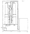
- Fig.1 - Show a schematic representation of an example of the present invention, developed to extract fungal spores.
- 1-Reservoir tank with the initial suspension, containing the spores mixture and other solid particles from which the spores should be separated.
- This invention uses the solid particles tridimensional form characteristics, which can be used when solids are in suspensions, to separate through wet filtration, a mixture of solid particles with different diameters, that can be retained in filtration fabrics of appropriate mesh dimensions, to separate a given set of particles of known said diameter, from others of also known set of said diameter.
- a clogging layer is formed, that is overcome in this invention, by the use of a closed circuit under vacuum, to allow reverse suspension flow direction and air suction through the said filtration fabric.
- the solid particles can then be dryed, using air suction and collected on the top of the said filtration fabric.
- the said separation process is achieved in this invention, by the use of two filters with filtration fabric membrane, placed one after another, in a closed circuit, where the suspension flows.
- the first said filter having the mesh appropriate to collect the solid particles with bigger diameter
- the second said filter having the appropriate mesh to collect the solid particles with smaller diameter.
- the said wet filtration process preferably uses two vessels, one on the top of the membrane filter fabric, and another under the said filter.
- the process starts by filling the first vessel with appropriate suspension and is characterized by vacuum aplication to the vessel placed after the filtration membrane, and at the same time by air flow into the vessel placed before the filtration membrane, causing pressure over the fabric membrane due to the weigth of the liquid on the top vessel, and the vacuum in the under vessel, causing the liquid to flow through the membrane fabric filter.
- the clogging of filter fabric membrane which occurs during the filtration process, is overcome by the reverse flow direction of the suspension and by the air suction through the membrane fabric of the filter in the reverse direction of the suspension flow during filtration.
- the said reverse flow direction and air suction are applied during a short period, just enough to allow a few air bubles to appear in the suspension in the reverse direction of suspension flow during filtration.
- the said method to overcome clogging comprises:
- the said separation process is accomplished by performing the said filtration and the said process of overcome clogging, in the both said filtration filter fabrics, and is complemented by the elimination of the solids retained in the first filter fabric and by the collection of the solids in the second filter fabric.
- the said collection can be made after drying the solids according to the following procedures:
- the speed of the drying process can be increased, by alternating the air flow direction during the drying process, by
- the collection of solids is performed by cleaning the fabric surface using a soft scraper tool to collect it, avoiding hurting the surface.
- the vacuum used to preform the operations should be in the range from -0,9 bar to -0,2 bar.
- the fabric used can be made from several materials, but should allow a certain degree of deformation without loosing the mesh properties, under the stated vacuum conditions.
- Apparatus to separate fungal spores from solid medium shown in Fig. 1 .
- Fungal spores must be bigger than 11 ⁇ m and smaller than 44 ⁇ m (average diameter 22 ⁇ m, 95 % ranging from 12 to 31 ⁇ m), mixed with solid medium particles used for growing the fungus, of variable diameter but all bigger than 44 ⁇ m.
- This apparatus is constituted by a support structure and three interconnected systems:
- Two filters with cylindric shape, made of hard PVC, 10 cm hight x 20 cm diameter, with nylon filtration fabric (supplied by Lockertex U.K. ).
- the reservoirs (2, 4, 24, and 22) are placed in succession, connected by the filters (3, 23) or by the suspension transport tubes (25).
- the system is fed with suspension from the reservoir (1), through one tube (25), to the reservoir (2).
- the reservoir (2) is connected to the reservoir (4) by the filter (3), both supported by the support structure.
- the filter (3) stands in an easy operating aperture that has 2 closing rubber o-rings, one at the upper part and another at the lower part and which are strongly attached to the vessels, to allow the application of said vacuum.
- the reservoir (24) is fed with suspension from reservoir (4), by a tube (25).
- the reservoir (24) is connected to the reservoir (22) by the filter (23), both supported by the support structure, and using an easy operating aperture as described to filter (3).
- Both reservoirs (4) and (22) have draining tubes (25).
- the vacuum system constituition:
- the vacuum pump is connected to the reservoirs (2), (4), (24) and (22), through vacuum pipes (6), with the vacuum trap (9) placed to avoid liquid suspension suction into the pump.
- the vacuum pump (5) is connected to the lower end of the vacuum trap (9) through a tube (6).
- the vacuum trap (9) upper end is connected to all reservoirs (2), (4), (24) and (22), allowing air suction to the said reservoirs.
- Each of the said reservoirs has attached an air entrance (13), (11), (18) and (17) respectively, allowing air flow, if necessary.
- the said air entrance is connected through a tube (6) and in reservoirs (2) and (24), the said air entrance is connected through a tube (25).
- control system constituition:
- Vacuum controller (28) (0 to -1 bar).
- the vacuum controller is connected to the upper part of the liquid trap, allowing the acquisition of information about the vacuum in each part of the system, allowing to take the decisions in closing or opening the said air and/or vacuum valves to perform the vacuum and air flow cycles.
- This example relates to the procedure used to separate clamydospores of the fungus Pochonia chlamydosporia from the solid medium in which it was produced.
- the medium particles diameter ranges between 44 ⁇ m and 2000 ⁇ m, and the diameter of clamydospores is bigger than 10 ⁇ m and smaller than 44 ⁇ m (average diameter 22 ⁇ m, and 95 % confidance interval ranging from 12 to 31 ⁇ m)
- A.1- Keep all valves closed except valves (7) and (8).
- valves (16) and (18) open until the air flow passes through the filter (23) and vacuum reaches -0.2 bar or less.
- H.4- Repeat operations H.1 to H.3 four to six times until the clamydospores moisture reaches the desired level.
- I.6- Open the aperture of filter (23), and collect the clamydospores, by scraping them to an appropriate container, with a soft tool, to avoid hurting the filter fabric.
Landscapes
- Chemical & Material Sciences (AREA)
- Chemical Kinetics & Catalysis (AREA)
- Filtration Of Liquid (AREA)
- Separation Using Semi-Permeable Membranes (AREA)
Claims (5)
- Vorrichtung zur Durchführung eines Verfahrens zur Trennung von festen Teilchen in einer flussigen Suspension, umfassend
ein Filtersystem mit- ersten und zweiten Filtern (3, 23) mit Filtergeweben, wobei die Filter (3, 23) einer nach dem anderen angeordnet sind,- einem ersten stromaufwärts gelegenen Reservoir (2) und einem ersten stromabwärts gelegenen Reservoir (4), dass unterhalb des ersten stromaufwärts gelegenen Reservoirs (2) angeordnet ist, wobei der erste Filter (3) zwischen dem ersten stromaufwärts gelegenen und dem ersten stromabwärts gelegenen Reservoiren (2, 4) angeordnet ist,- einem zweiten stromaufwärts gelegenen Reservoir (24) und einem zweiten stromabwärts gelegenen Reservoir (22), dass unterhalb des zweiten stromaufwärts gelegenen Reservoirs (24) angeordnet ist, wobei der zweite Filter (23) zwischen dem zweiten stromaufwärts gelegenen und dem zweiten stromabwärts gelegenen Reservoiren (24, 22) angeordnet ist,- ein erstes mit dem ersten stromaufwärts gelegenen Reservoir (2) verbundenes Transportrohr für flüssige Suspension (25) zum Transportieren von anfänglicher flüssiger Suspension zum dem ersten stromaufwärts gelegenen Reservoir (2), und- ein zweites das erste stromabwärts gelegene Reservoir (4) und das zweite stromaufwärts gelegene Reservoir (24) verbindendes Transportrohr für flüssige Suspension zum Transportieren von flüssiger Suspension aus dem ersten stromabwärts gelegenen Reservoir (4) zum zweiten stromaufwärts gelegenen Reservoir (24);ein Vakuumsystem mit- einer Vakuumpumpe (5), die über Luftsaugrohre (6) mit der Oberseite der ersten stromaufwärts gelegenen und stromabwärts gelegenen Reservoire (2, 4) und mit der Oberseite der zweiten stromaufwärts gelegenen und stromabwärts gelegenen Reservoire (24, 22) verbunden ist, und- Lufteingängen die mit der Oberseite des ersten stromaufwärts gelegenen und stromabwärts gelegenen Reservoirs (2, 4) und mit der Oberseite des zweiten stromaufwärts gelegenen und stromabwärts gelegenen Reservoirs (24, 22) verbunden sind; undeine Steuersystem mit- Steuerventilen für flüssige Suspension Strömungen (14, 20, 19, 21) zum Steuern flüssiger Suspension Strömungen in dem ersten und dem zweiten Transportrohr für flüssige Suspension (25),- mit den oben gennanten Lufteingängen verbundenen Lufteintrittsteuerventilen (8, 13, 11, 18, 17) zum Steuern des Lufteintritts in die ersten und zweiten stromaufwärts gelegenen und stromabwärts gelegenen Reservoire (2, 4, 24, 22), und Vakuumsteuerventile (7, 12, 10, 15, 16) zum Steuern von Vakuum in den Luftsaugrohren (6)- wodurch das dem ersten und dem zweiten stromabwärts gelegenen Reservoir (4, 22) zuzuführende Vakuum mit Luft an der Oberseite des ersten und des zweiten stromaufwärts gelegenen Reservoirs zugelassen ist, um dadurch die flüssige Suspension dazu zu zwingen in einer Strömungsrichtung der flüssigen Suspension aus dem ersten und dem zweiten stromaufwärts gelegenen Reservoir (4, 22) durch die Filter (3, 23) jeweils in das erste und das zweite stromabwärts gelegene Reservoir zu fliessen (4, 22), und- ermöglicht dass das dem ersten und dem zweiten stromaufwärts gelegenen Reservoir (2, 24) zuzuführende Vakuum mit Luft an der Oberseite der stromaufwärts gelegenen Reservoirs (4, 22) zugelassen ist, um dadurch die flüssige Suspension dazu zu zwingen durch die Filter (3, 23) in einer entgegengesetzten Richtung zu fliessen und Luft durch die Filtergewebe anzusaugen, um die Filtergewebe der Filter (3, 23) zu reinigen. - Vorrichtung nach Anspruch 1, wobei die ersten stromaufwärts und stromabwärts Reservoire (2, 4) und die zweiten stromaufwärts und stromabwärts Reservoire (24, 22) jeweils als Spaltenreservoirs vorgesehen sind.
- Vorrichtung nach Anspruch 2, wobei die Filter (3, 23) bewegliche Filter sind die in Vakuum versiegelten Öffnungen angebracht sind, dadurch die Spaltenreservoirs verbinden.
- Vorrichtung nach Anspruch 1, wobei das Vakuumsystem so vorbereitet ist, dass es mit einem Vakuum von -0.2 bis -0.9 bar funktionniert.
- Verwendung der Vorrichtung nach einem der Ansprüche 1 bis 4 zur Trennung von Pilzsporen aus flüssigen Suspensionen, die die oben genannten Sporen und festen Teilchen des Kulturmediums umfassen.
Priority Applications (2)
| Application Number | Priority Date | Filing Date | Title |
|---|---|---|---|
| PL09165221T PL2127718T3 (pl) | 2004-05-28 | 2004-05-28 | Urządzenie do rozdziału zawiesiny cząstek stałych w cieczy na drodze filtracji ze wspomaganiem odtykania filtra |
| DK09165221.4T DK2127718T3 (da) | 2004-05-28 | 2004-05-28 | Apparat til separation af faststof- og væskesuspensioner ved filtrering understøttet af filter-unclogging |
Applications Claiming Priority (2)
| Application Number | Priority Date | Filing Date | Title |
|---|---|---|---|
| EP04735427A EP1750826B1 (de) | 2004-05-28 | 2004-05-28 | Verfahren und vorrichtung zur trennung von feststoffen und flüssigkeitssuspensionen durch filterabreinigungsunterstützte filtration |
| PCT/PT2004/000009 WO2005115584A1 (en) | 2004-05-28 | 2004-05-28 | Method and apparatus for separation of solids and liquid suspensions by filter unclogging aided filtration |
Related Parent Applications (1)
| Application Number | Title | Priority Date | Filing Date |
|---|---|---|---|
| EP04735427A Division EP1750826B1 (de) | 2004-05-28 | 2004-05-28 | Verfahren und vorrichtung zur trennung von feststoffen und flüssigkeitssuspensionen durch filterabreinigungsunterstützte filtration |
Publications (2)
| Publication Number | Publication Date |
|---|---|
| EP2127718A1 EP2127718A1 (de) | 2009-12-02 |
| EP2127718B1 true EP2127718B1 (de) | 2012-10-03 |
Family
ID=34957763
Family Applications (2)
| Application Number | Title | Priority Date | Filing Date |
|---|---|---|---|
| EP09165221A Expired - Lifetime EP2127718B1 (de) | 2004-05-28 | 2004-05-28 | Vorrichtung zur Trennung von Feststoff- und Flüssigsuspensionen durch filterentstopfungsunterstützte Filtrierung |
| EP04735427A Expired - Lifetime EP1750826B1 (de) | 2004-05-28 | 2004-05-28 | Verfahren und vorrichtung zur trennung von feststoffen und flüssigkeitssuspensionen durch filterabreinigungsunterstützte filtration |
Family Applications After (1)
| Application Number | Title | Priority Date | Filing Date |
|---|---|---|---|
| EP04735427A Expired - Lifetime EP1750826B1 (de) | 2004-05-28 | 2004-05-28 | Verfahren und vorrichtung zur trennung von feststoffen und flüssigkeitssuspensionen durch filterabreinigungsunterstützte filtration |
Country Status (9)
| Country | Link |
|---|---|
| US (2) | US20070292935A1 (de) |
| EP (2) | EP2127718B1 (de) |
| AT (1) | ATE443558T1 (de) |
| CA (1) | CA2567472C (de) |
| DE (1) | DE602004023332D1 (de) |
| DK (2) | DK1750826T3 (de) |
| ES (2) | ES2396275T3 (de) |
| PL (2) | PL1750826T3 (de) |
| WO (1) | WO2005115584A1 (de) |
Families Citing this family (5)
| Publication number | Priority date | Publication date | Assignee | Title |
|---|---|---|---|---|
| RU2309785C2 (ru) * | 2006-01-10 | 2007-11-10 | Ооо Нпп "Бмт" | Вакуумная станция |
| IL189249A0 (en) * | 2008-02-04 | 2008-11-03 | Orit Keinan | A nail filing apparatus |
| IL200359A0 (en) * | 2009-08-12 | 2010-05-31 | Mordechai Deutsch | Particle separtation |
| CN101757808B (zh) * | 2010-02-05 | 2011-06-15 | 山东棉花研究中心 | 恒压式过滤仪 |
| GB201315905D0 (en) | 2013-09-06 | 2013-10-23 | Alconbury Weston Ltd | Filtration apparatus |
Family Cites Families (10)
| Publication number | Priority date | Publication date | Assignee | Title |
|---|---|---|---|---|
| US3630360A (en) * | 1969-04-08 | 1971-12-28 | North American Rockwell | Filtering system for fine suspensions |
| US4282105A (en) * | 1980-01-28 | 1981-08-04 | J. R. Schneider Co., Inc. | Filter |
| US4443421A (en) * | 1982-03-16 | 1984-04-17 | Occidental Chemical Corporation | Process for removing particulate impurities from aqueous phosphoric acid |
| US4702845A (en) * | 1986-02-06 | 1987-10-27 | Amsted Industries Incorporated | Rotary drum filter |
| FI79031C (fi) * | 1988-08-03 | 1989-11-10 | Larox Ag | Filtreringsfoerfarande. |
| FI943437A7 (fi) * | 1992-01-22 | 1994-09-21 | Eec Int Inc | Laite mineraalilietteen suodattamiseksi |
| US5217509A (en) * | 1992-04-03 | 1993-06-08 | Industrial Air, Inc. | Filtration system |
| CA2126802C (en) * | 1994-06-27 | 1999-08-17 | Hermann Ophardt | Powder paint booth backflow filter apparatus |
| DE19717448A1 (de) * | 1997-04-25 | 1997-10-02 | Peter Dr Lueth | Vorrichtung und Filtrationsverfahren zur Abtrennung von Stoffen aus Suspensionen |
| US7803608B2 (en) * | 2001-02-28 | 2010-09-28 | Biomerieux, Inc. | Integrated filtration and detection device |
-
2004
- 2004-05-28 WO PCT/PT2004/000009 patent/WO2005115584A1/en not_active Ceased
- 2004-05-28 US US11/597,713 patent/US20070292935A1/en not_active Abandoned
- 2004-05-28 PL PL04735427T patent/PL1750826T3/pl unknown
- 2004-05-28 EP EP09165221A patent/EP2127718B1/de not_active Expired - Lifetime
- 2004-05-28 CA CA2567472A patent/CA2567472C/en not_active Expired - Fee Related
- 2004-05-28 DK DK04735427.9T patent/DK1750826T3/da active
- 2004-05-28 DE DE602004023332T patent/DE602004023332D1/de not_active Expired - Lifetime
- 2004-05-28 ES ES09165221T patent/ES2396275T3/es not_active Expired - Lifetime
- 2004-05-28 EP EP04735427A patent/EP1750826B1/de not_active Expired - Lifetime
- 2004-05-28 ES ES04735427T patent/ES2335499T3/es not_active Expired - Lifetime
- 2004-05-28 DK DK09165221.4T patent/DK2127718T3/da active
- 2004-05-28 AT AT04735427T patent/ATE443558T1/de not_active IP Right Cessation
- 2004-05-28 PL PL09165221T patent/PL2127718T3/pl unknown
-
2010
- 2010-02-22 US US12/709,916 patent/US20100140191A1/en not_active Abandoned
Also Published As
| Publication number | Publication date |
|---|---|
| US20100140191A1 (en) | 2010-06-10 |
| ES2335499T3 (es) | 2010-03-29 |
| EP2127718A1 (de) | 2009-12-02 |
| PL2127718T3 (pl) | 2013-03-29 |
| CA2567472A1 (en) | 2005-12-08 |
| PL1750826T3 (pl) | 2010-03-31 |
| ATE443558T1 (de) | 2009-10-15 |
| US20070292935A1 (en) | 2007-12-20 |
| DE602004023332D1 (de) | 2009-11-05 |
| DK2127718T3 (da) | 2013-01-14 |
| DK1750826T3 (da) | 2010-02-01 |
| WO2005115584A1 (en) | 2005-12-08 |
| EP1750826A1 (de) | 2007-02-14 |
| ES2396275T3 (es) | 2013-02-20 |
| CA2567472C (en) | 2013-04-23 |
| EP1750826B1 (de) | 2009-09-23 |
Similar Documents
| Publication | Publication Date | Title |
|---|---|---|
| CN1265867C (zh) | 清洗薄膜过滤组件的方法 | |
| US5227076A (en) | Method and apparatus for thickening fine particle suspensions | |
| JP2010501340A (ja) | 低圧逆洗 | |
| US10486089B2 (en) | Method and system for filtration and filtration cake layer formation | |
| CN101043933A (zh) | 反洗废液的减少 | |
| AT511926B1 (de) | Verfahren zur mechanischen Feststoffabscheidung aus Abwasser | |
| JPH08323161A (ja) | 浸漬型膜分離装置及びこれを用いた膜分離方法 | |
| CN105478016A (zh) | 一种自动反冲洗刮擦管式膜过滤装置 | |
| JPH0975689A (ja) | 分離膜モジュールの洗浄方法 | |
| US20100140191A1 (en) | Method and apparatus for separation of solids and liquid suspensions by filter unclogging aided filtration | |
| EP2342316A1 (de) | Verfahren zur filtration einer bioreaktorflüssigkeit aus einem bioreaktor; querstrom-membranmodul und bioreaktormembransystem | |
| CN107779372B (zh) | 一种带有反冲装置的过滤系统和过滤方法 | |
| WO2010027166A2 (ko) | 자동 세척 필터 장치 제어 방법 | |
| US5252230A (en) | Granulated filter for the filtration of fine graded suspensions | |
| JPH07251041A (ja) | 膜分離装置及びその洗浄方法 | |
| JP2000084377A (ja) | 管状膜装置の膜汚染物質除去方法 | |
| JPH09155166A (ja) | 浸漬型平膜分離装置 | |
| JP2691846B2 (ja) | 固液分離方法及びその装置 | |
| JP4678757B2 (ja) | 水処理装置およびその運転方法 | |
| JPH05212254A (ja) | 中空糸膜モジュールろ過装置 | |
| CN103596657B (zh) | 用于过滤和滤饼层形成的方法和系统 | |
| JP2023135069A (ja) | 微生物の分離回収方法及び微生物の分離回収装置 | |
| JPH0751548A (ja) | セラミック膜の逆洗方法 | |
| JPH07214091A (ja) | 廃水処理装置 | |
| JPH05293310A (ja) | 沈降性ろ材を用いたろ過機におけるろ材の洗浄装置 |
Legal Events
| Date | Code | Title | Description |
|---|---|---|---|
| PUAI | Public reference made under article 153(3) epc to a published international application that has entered the european phase |
Free format text: ORIGINAL CODE: 0009012 |
|
| AC | Divisional application: reference to earlier application |
Ref document number: 1750826 Country of ref document: EP Kind code of ref document: P |
|
| AK | Designated contracting states |
Kind code of ref document: A1 Designated state(s): AT BE BG CH CY CZ DE DK EE ES FI FR GB GR HU IE IT LI LU MC NL PL PT RO SE SI SK TR |
|
| 17P | Request for examination filed |
Effective date: 20100518 |
|
| 17Q | First examination report despatched |
Effective date: 20100906 |
|
| GRAP | Despatch of communication of intention to grant a patent |
Free format text: ORIGINAL CODE: EPIDOSNIGR1 |
|
| RTI1 | Title (correction) |
Free format text: APPARATUS FOR SEPARATION OF SOLIDS AND LIQUID SUSPENSIONS BY FILTER UNCLOGGING AIDED FILTRATION |
|
| GRAS | Grant fee paid |
Free format text: ORIGINAL CODE: EPIDOSNIGR3 |
|
| GRAA | (expected) grant |
Free format text: ORIGINAL CODE: 0009210 |
|
| AC | Divisional application: reference to earlier application |
Ref document number: 1750826 Country of ref document: EP Kind code of ref document: P |
|
| AK | Designated contracting states |
Kind code of ref document: B1 Designated state(s): AT BE BG CH CY CZ DE DK EE ES FI FR GB GR HU IE IT LI LU MC NL PL PT RO SE SI SK TR |
|
| REG | Reference to a national code |
Ref country code: GB Ref legal event code: FG4D |
|
| REG | Reference to a national code |
Ref country code: AT Ref legal event code: REF Ref document number: 577700 Country of ref document: AT Kind code of ref document: T Effective date: 20121015 Ref country code: CH Ref legal event code: EP |
|
| REG | Reference to a national code |
Ref country code: IE Ref legal event code: FG4D |
|
| REG | Reference to a national code |
Ref country code: DE Ref legal event code: R096 Ref document number: 602004039588 Country of ref document: DE Effective date: 20121129 |
|
| REG | Reference to a national code |
Ref country code: RO Ref legal event code: EPE |
|
| REG | Reference to a national code |
Ref country code: CH Ref legal event code: NV Representative=s name: HEPP WENGER RYFFEL AG, CH |
|
| REG | Reference to a national code |
Ref country code: DK Ref legal event code: T3 |
|
| REG | Reference to a national code |
Ref country code: SE Ref legal event code: TRGR |
|
| REG | Reference to a national code |
Ref country code: NL Ref legal event code: T3 |
|
| REG | Reference to a national code |
Ref country code: ES Ref legal event code: FG2A Ref document number: 2396275 Country of ref document: ES Kind code of ref document: T3 Effective date: 20130220 |
|
| PG25 | Lapsed in a contracting state [announced via postgrant information from national office to epo] |
Ref country code: SI Free format text: LAPSE BECAUSE OF FAILURE TO SUBMIT A TRANSLATION OF THE DESCRIPTION OR TO PAY THE FEE WITHIN THE PRESCRIBED TIME-LIMIT Effective date: 20121003 |
|
| REG | Reference to a national code |
Ref country code: PL Ref legal event code: T3 Ref country code: GR Ref legal event code: EP Ref document number: 20130400001 Country of ref document: GR Effective date: 20130225 |
|
| PG25 | Lapsed in a contracting state [announced via postgrant information from national office to epo] |
Ref country code: PT Free format text: LAPSE BECAUSE OF FAILURE TO SUBMIT A TRANSLATION OF THE DESCRIPTION OR TO PAY THE FEE WITHIN THE PRESCRIBED TIME-LIMIT Effective date: 20130204 Ref country code: CY Free format text: LAPSE BECAUSE OF FAILURE TO SUBMIT A TRANSLATION OF THE DESCRIPTION OR TO PAY THE FEE WITHIN THE PRESCRIBED TIME-LIMIT Effective date: 20121003 |
|
| PG25 | Lapsed in a contracting state [announced via postgrant information from national office to epo] |
Ref country code: EE Free format text: LAPSE BECAUSE OF FAILURE TO SUBMIT A TRANSLATION OF THE DESCRIPTION OR TO PAY THE FEE WITHIN THE PRESCRIBED TIME-LIMIT Effective date: 20121003 Ref country code: SK Free format text: LAPSE BECAUSE OF FAILURE TO SUBMIT A TRANSLATION OF THE DESCRIPTION OR TO PAY THE FEE WITHIN THE PRESCRIBED TIME-LIMIT Effective date: 20121003 |
|
| PLBE | No opposition filed within time limit |
Free format text: ORIGINAL CODE: 0009261 |
|
| STAA | Information on the status of an ep patent application or granted ep patent |
Free format text: STATUS: NO OPPOSITION FILED WITHIN TIME LIMIT |
|
| 26N | No opposition filed |
Effective date: 20130704 |
|
| REG | Reference to a national code |
Ref country code: DE Ref legal event code: R097 Ref document number: 602004039588 Country of ref document: DE Effective date: 20130704 |
|
| REG | Reference to a national code |
Ref country code: HU Ref legal event code: AG4A Ref document number: E017230 Country of ref document: HU |
|
| BERE | Be: lapsed |
Owner name: UNIVERSIDADE EVORA Effective date: 20130531 |
|
| REG | Reference to a national code |
Ref country code: NL Ref legal event code: V1 Effective date: 20131201 |
|
| PG25 | Lapsed in a contracting state [announced via postgrant information from national office to epo] |
Ref country code: MC Free format text: LAPSE BECAUSE OF FAILURE TO SUBMIT A TRANSLATION OF THE DESCRIPTION OR TO PAY THE FEE WITHIN THE PRESCRIBED TIME-LIMIT Effective date: 20121003 |
|
| REG | Reference to a national code |
Ref country code: CH Ref legal event code: PL |
|
| REG | Reference to a national code |
Ref country code: SE Ref legal event code: EUG |
|
| GBPC | Gb: european patent ceased through non-payment of renewal fee |
Effective date: 20130528 |
|
| PG25 | Lapsed in a contracting state [announced via postgrant information from national office to epo] |
Ref country code: CH Free format text: LAPSE BECAUSE OF NON-PAYMENT OF DUE FEES Effective date: 20130531 Ref country code: SE Free format text: LAPSE BECAUSE OF NON-PAYMENT OF DUE FEES Effective date: 20130529 Ref country code: DE Free format text: LAPSE BECAUSE OF NON-PAYMENT OF DUE FEES Effective date: 20131203 Ref country code: CZ Free format text: LAPSE BECAUSE OF NON-PAYMENT OF DUE FEES Effective date: 20130528 Ref country code: LI Free format text: LAPSE BECAUSE OF NON-PAYMENT OF DUE FEES Effective date: 20130531 |
|
| REG | Reference to a national code |
Ref country code: GR Ref legal event code: ML Ref document number: 20130400001 Country of ref document: GR Effective date: 20131204 |
|
| REG | Reference to a national code |
Ref country code: DK Ref legal event code: EBP Effective date: 20130531 |
|
| REG | Reference to a national code |
Ref country code: IE Ref legal event code: MM4A |
|
| REG | Reference to a national code |
Ref country code: DE Ref legal event code: R119 Ref document number: 602004039588 Country of ref document: DE Effective date: 20131203 |
|
| PG25 | Lapsed in a contracting state [announced via postgrant information from national office to epo] |
Ref country code: FI Free format text: LAPSE BECAUSE OF NON-PAYMENT OF DUE FEES Effective date: 20130528 Ref country code: IT Free format text: LAPSE BECAUSE OF NON-PAYMENT OF DUE FEES Effective date: 20130528 Ref country code: BE Free format text: LAPSE BECAUSE OF NON-PAYMENT OF DUE FEES Effective date: 20130531 Ref country code: GR Free format text: LAPSE BECAUSE OF NON-PAYMENT OF DUE FEES Effective date: 20131204 Ref country code: NL Free format text: LAPSE BECAUSE OF NON-PAYMENT OF DUE FEES Effective date: 20131201 Ref country code: RO Free format text: LAPSE BECAUSE OF NON-PAYMENT OF DUE FEES Effective date: 20121003 Ref country code: HU Free format text: LAPSE BECAUSE OF NON-PAYMENT OF DUE FEES Effective date: 20130529 |
|
| REG | Reference to a national code |
Ref country code: FR Ref legal event code: ST Effective date: 20140131 |
|
| PG25 | Lapsed in a contracting state [announced via postgrant information from national office to epo] |
Ref country code: IE Free format text: LAPSE BECAUSE OF NON-PAYMENT OF DUE FEES Effective date: 20130528 Ref country code: DK Free format text: LAPSE BECAUSE OF NON-PAYMENT OF DUE FEES Effective date: 20130531 Ref country code: GB Free format text: LAPSE BECAUSE OF NON-PAYMENT OF DUE FEES Effective date: 20130528 |
|
| PG25 | Lapsed in a contracting state [announced via postgrant information from national office to epo] |
Ref country code: FR Free format text: LAPSE BECAUSE OF NON-PAYMENT OF DUE FEES Effective date: 20130531 |
|
| REG | Reference to a national code |
Ref country code: ES Ref legal event code: FD2A Effective date: 20140606 |
|
| REG | Reference to a national code |
Ref country code: AT Ref legal event code: MM01 Ref document number: 577700 Country of ref document: AT Kind code of ref document: T Effective date: 20130528 |
|
| PG25 | Lapsed in a contracting state [announced via postgrant information from national office to epo] |
Ref country code: BG Free format text: LAPSE BECAUSE OF NON-PAYMENT OF DUE FEES Effective date: 20140630 Ref country code: AT Free format text: LAPSE BECAUSE OF NON-PAYMENT OF DUE FEES Effective date: 20130528 Ref country code: PL Free format text: LAPSE BECAUSE OF NON-PAYMENT OF DUE FEES Effective date: 20130528 Ref country code: ES Free format text: LAPSE BECAUSE OF NON-PAYMENT OF DUE FEES Effective date: 20130529 |
|
| REG | Reference to a national code |
Ref country code: PL Ref legal event code: LAPE |
|
| PG25 | Lapsed in a contracting state [announced via postgrant information from national office to epo] |
Ref country code: BG Free format text: LAPSE BECAUSE OF NON-PAYMENT OF DUE FEES Effective date: 20130531 |
|
| PG25 | Lapsed in a contracting state [announced via postgrant information from national office to epo] |
Ref country code: TR Free format text: LAPSE BECAUSE OF FAILURE TO SUBMIT A TRANSLATION OF THE DESCRIPTION OR TO PAY THE FEE WITHIN THE PRESCRIBED TIME-LIMIT Effective date: 20121003 |
|
| PG25 | Lapsed in a contracting state [announced via postgrant information from national office to epo] |
Ref country code: LU Free format text: LAPSE BECAUSE OF NON-PAYMENT OF DUE FEES Effective date: 20130528 |