EP2127043B1 - Prise femelle electrique annexe pour vehicule automobile - Google Patents
Prise femelle electrique annexe pour vehicule automobile Download PDFInfo
- Publication number
- EP2127043B1 EP2127043B1 EP08709236.7A EP08709236A EP2127043B1 EP 2127043 B1 EP2127043 B1 EP 2127043B1 EP 08709236 A EP08709236 A EP 08709236A EP 2127043 B1 EP2127043 B1 EP 2127043B1
- Authority
- EP
- European Patent Office
- Prior art keywords
- assembly
- piece assembly
- unitary body
- female socket
- axial
- Prior art date
- Legal status (The legal status is an assumption and is not a legal conclusion. Google has not performed a legal analysis and makes no representation as to the accuracy of the status listed.)
- Active
Links
Images


Classifications
-
- H—ELECTRICITY
- H01—ELECTRIC ELEMENTS
- H01R—ELECTRICALLY-CONDUCTIVE CONNECTIONS; STRUCTURAL ASSOCIATIONS OF A PLURALITY OF MUTUALLY-INSULATED ELECTRICAL CONNECTING ELEMENTS; COUPLING DEVICES; CURRENT COLLECTORS
- H01R24/00—Two-part coupling devices, or either of their cooperating parts, characterised by their overall structure
- H01R24/38—Two-part coupling devices, or either of their cooperating parts, characterised by their overall structure having concentrically or coaxially arranged contacts
-
- H—ELECTRICITY
- H01—ELECTRIC ELEMENTS
- H01R—ELECTRICALLY-CONDUCTIVE CONNECTIONS; STRUCTURAL ASSOCIATIONS OF A PLURALITY OF MUTUALLY-INSULATED ELECTRICAL CONNECTING ELEMENTS; COUPLING DEVICES; CURRENT COLLECTORS
- H01R13/00—Details of coupling devices of the kinds covered by groups H01R12/70 or H01R24/00 - H01R33/00
- H01R13/73—Means for mounting coupling parts to apparatus or structures, e.g. to a wall
- H01R13/74—Means for mounting coupling parts in openings of a panel
- H01R13/741—Means for mounting coupling parts in openings of a panel using snap fastening means
- H01R13/743—Means for mounting coupling parts in openings of a panel using snap fastening means integral with the housing
-
- H—ELECTRICITY
- H01—ELECTRIC ELEMENTS
- H01R—ELECTRICALLY-CONDUCTIVE CONNECTIONS; STRUCTURAL ASSOCIATIONS OF A PLURALITY OF MUTUALLY-INSULATED ELECTRICAL CONNECTING ELEMENTS; COUPLING DEVICES; CURRENT COLLECTORS
- H01R13/00—Details of coupling devices of the kinds covered by groups H01R12/70 or H01R24/00 - H01R33/00
- H01R13/40—Securing contact members in or to a base or case; Insulating of contact members
- H01R13/42—Securing in a demountable manner
-
- H—ELECTRICITY
- H01—ELECTRIC ELEMENTS
- H01R—ELECTRICALLY-CONDUCTIVE CONNECTIONS; STRUCTURAL ASSOCIATIONS OF A PLURALITY OF MUTUALLY-INSULATED ELECTRICAL CONNECTING ELEMENTS; COUPLING DEVICES; CURRENT COLLECTORS
- H01R13/00—Details of coupling devices of the kinds covered by groups H01R12/70 or H01R24/00 - H01R33/00
- H01R13/46—Bases; Cases
- H01R13/50—Bases; Cases formed as an integral body
-
- H—ELECTRICITY
- H01—ELECTRIC ELEMENTS
- H01R—ELECTRICALLY-CONDUCTIVE CONNECTIONS; STRUCTURAL ASSOCIATIONS OF A PLURALITY OF MUTUALLY-INSULATED ELECTRICAL CONNECTING ELEMENTS; COUPLING DEVICES; CURRENT COLLECTORS
- H01R2103/00—Two poles
-
- H—ELECTRICITY
- H01—ELECTRIC ELEMENTS
- H01R—ELECTRICALLY-CONDUCTIVE CONNECTIONS; STRUCTURAL ASSOCIATIONS OF A PLURALITY OF MUTUALLY-INSULATED ELECTRICAL CONNECTING ELEMENTS; COUPLING DEVICES; CURRENT COLLECTORS
- H01R2201/00—Connectors or connections adapted for particular applications
- H01R2201/26—Connectors or connections adapted for particular applications for vehicles
-
- H—ELECTRICITY
- H01—ELECTRIC ELEMENTS
- H01R—ELECTRICALLY-CONDUCTIVE CONNECTIONS; STRUCTURAL ASSOCIATIONS OF A PLURALITY OF MUTUALLY-INSULATED ELECTRICAL CONNECTING ELEMENTS; COUPLING DEVICES; CURRENT COLLECTORS
- H01R43/00—Apparatus or processes specially adapted for manufacturing, assembling, maintaining, or repairing of line connectors or current collectors or for joining electric conductors
- H01R43/16—Apparatus or processes specially adapted for manufacturing, assembling, maintaining, or repairing of line connectors or current collectors or for joining electric conductors for manufacturing contact members, e.g. by punching and by bending
-
- H—ELECTRICITY
- H01—ELECTRIC ELEMENTS
- H01R—ELECTRICALLY-CONDUCTIVE CONNECTIONS; STRUCTURAL ASSOCIATIONS OF A PLURALITY OF MUTUALLY-INSULATED ELECTRICAL CONNECTING ELEMENTS; COUPLING DEVICES; CURRENT COLLECTORS
- H01R43/00—Apparatus or processes specially adapted for manufacturing, assembling, maintaining, or repairing of line connectors or current collectors or for joining electric conductors
- H01R43/20—Apparatus or processes specially adapted for manufacturing, assembling, maintaining, or repairing of line connectors or current collectors or for joining electric conductors for assembling or disassembling contact members with insulating base, case or sleeve
Definitions
- the present invention is in the field of automotive equipment relating to conductive connections of electricity from a structural association of several electrical connection elements isolated from each other. It relates to an auxiliary female electrical outlet intended to equip a motor vehicle for the occasional power supply of an accessory provided with a complementary plug connection.
- connection plug comprising a generally cylindrical conformation body, which carries at its periphery a first connection pad and at its distal end of a second pad connection.
- the socket comprises a first conductive element which is shaped as a cylinder for its connection with the body of the plug, this cylinder being extended by a first plug.
- a second conductive element is formed in platinum against which bears the second stud of the plug, this plate being extended by a second plug.
- the plugs are designed to be connected respectively to a voltage terminal and to a ground terminal of the electric circuit of the vehicle, in order to supply the accessory device with a low-voltage DC voltage, indicatively of the order of 12 V, 24 V, or even 42 V.
- An electrically insulating connector is placed at the distal end of the socket, to electrically insulate the conductive elements relative to each other, or even to provide a mechanical connection between the socket and terminals.
- the socket is equipped with a connecting member on a structural element of the vehicle, such as a dashboard, console or similar structural element.
- This joining member is for example shaped as a ring intended to be inserted inside a housing that includes for this purpose the structural element.
- the socket It is sought to obtain the socket at a lower cost, in particular by simplifying its structure and its methods of obtaining. It is desirable that the structure of the socket makes it possible to simplify the operations necessary for the assembly of the elements that compose it and for its mounting on the structural element of the vehicle. This simplification of structure must not be made to the detriment of the reliability of the electrical connection obtained between the plug and the terminals, and must not affect the robustness of the maintenance of the socket on the structural element of the vehicle. In view of these requirements, it must in particular be taken into account the frequent and repeated operations of introduction and withdrawal of the plug, and the structure of the socket must be intrinsically robust, reliable and durable in such a setting. use.
- a socket according to the preamble of claim 1 is described by the document EP-A2 1,164,666 .
- the object of the present invention is to provide a female electrical socket for equipping a motor vehicle for occasional power supply of an accessory equipped with a complementary male plug connection. It is more particularly the object of the present invention to provide such a socket that can be obtained cheaply and be easily installed on a structural element, while being robust, reliable and durable.
- the device of the present invention is a branch electrical socket according to claim 1 for equipping a motor vehicle, for occasional power supply of an accessory device equipped with a complementary male plug connection.
- the cylinder of the first conductive element is intended to cooperate with a body of the male plug carrying a first connection pad, while the first plug is intended to cooperate with the corresponding terminal of the electric circuit of the vehicle.
- the plate of the second conductive element is intended to be in axial contact with a second connection pad carried by the body of the plug, while the second plug is intended to cooperate with the terminal of the electrical circuit of the vehicle assigned to it.
- the connector is arranged to electrically isolate the conductive elements from each other, and preferably to provide a mechanical connection between the socket and the terminals.
- the ring and the connector are integrated in a one-piece assembly.
- the one-piece assembly advantageously constitutes a rigid interposing member between the structural element and the terminals of the electrical circuit, for the robust integration of the socket on the vehicle.
- the socket when mounting the socket on the vehicle, its positioning and its mechanical connection with the structural element and the terminals of the vehicle circuit respectively are facilitated.
- the socket comprises means for assembling between the unitary body and the one-piece assembly.
- These assembly means are likely to be of the advantageous type by interlocking via cooperating assembly members respectively integrated in the unitary body and the one-piece assembly. More particularly, the distribution of the organs necessary for the composition of the socket between two cohesive members respectively constituted by the unitary body and the monobloc assembly, allows to organize their easy assembly by interlocking by means of cooperating assembly members that they integrate construction respectively. It follows that the assembly means are obtained at lower cost and make the assembly methods of components of the socket quick and easy to implement.
- the female socket proposed by the invention is advantageously composed of a small number of elements assembled together, and in particular of the unitary body, of the one-piece assembly and of the second conductive element.
- the assembly of these elements together and the mounting of the female socket on the structural element of the vehicle, can be made by interlocking from their own structure, without using assembly members reported.
- the socket being adapted to be essentially composed of the unitary body and the one-piece assembly, which incorporate construction interlocking members for their assembly to one another and for mounting the socket on the structural element of the vehicle.
- the second conductive element may be structurally reduced to the platen and the second plug jointly formed from the same sheet of metal, being attached by interlocking on the connector which has a nesting relief provided for this purpose.
- These provisions are also such that the setting relative position between the terminals of the vehicle electrical circuit and the pads of the plug, is easily obtained in a rigorous manner from the assembly means of the unitary body and the monobloc assembly. one to another.
- These assembly means preferably incorporate radial positioning means and axial abutment means of the unitary body on the one-piece assembly when they are interlocked. to each other, so as to position the plugs in correspondence with the terminals.
- the connection between the plug and the terminals is obtained cheaply in a simple and easy way, with a robustness offered by the rigid nature of the monobloc assembly interposed between the structural element and the terminals, and with relative positioning. reliable between the plug and the terminals from the assembly means.
- the one-piece assembly is advantageously able to be formed by molding an electrically insulating plastic material.
- the proposed decomposition of the structure of the socket into a unitary body and into a one-piece assembly makes it possible to produce the ring and the connector in a single molding operation at a lower cost, and makes it possible to avoid assembly operations starting from integration of the organs necessary for their assembly to one another.
- the connection between the plug and the terminals is not only made mechanically robust, but also is electrically reliable releasing any risk of inadequate electrical connection.
- the assembly means are advantageously of the axial interlocking type of the unitary body within the monobloc assembly, and combine radial positioning means and axial positioning means of the unitary body with respect to the one-piece assembly.
- the radial positioning means advantageously consist of a first window formed in the connector for interlocking the first tongue.
- This first window is in particular radially offset with respect to the interlocking axis of the unitary body inside the monobloc assembly.
- the axial positioning means of the unitary body inside the monobloc assembly are more particularly means for limiting the axial introduction stroke of the unitary body towards the inside of the monoblock assembly, which are incidentally supplemented by a antagonistic axial support of the unitary body on the one-piece assembly.
- axial positioning means consist of a clipping assembly of the unitary body on the one-piece assembly between two axial opposing supports.
- These antagonistic axial supports are in particular constituted by cooperating junction members which are respectively integrated into the unitary body and to the one-piece assembly.
- the unitary body is axially supported by its bottom against the connector and incorporates a clip or similar counteracting bearing member against the one-piece assembly, such as against the edge of a window that includes the latter for example.
- these consist of a fold that includes the first tongue for its axial bearing against the connector.
- the connector incorporates a relief of receipt of this fold to reinforce its support at the bottom of the connector.
- the one-piece assembly comprises a cage formed of an extension of the ring to the connector. More particularly, this cage provides space for the passage of the plug to the connector connector, or even envelops the unitary body to protect it and avoid its inappropriate electrical contact with elements surrounding the socket installed on the structural element. Such a cage is also likely to be advantageously exploited for an assembly by elastic interlocking (clipping) between the unitary body and the one-piece assembly, or even between the one-piece assembly and the structural element of the vehicle.
- the cage and / or the unitary body are preferably elastically deformable under the effect of the introduction of the unitary body inside the monoblock assembly, for a fitting in narrow elastic interlocking of the unitary body inside the body.
- one piece assembly being advantageously obtained by molding a plastic material, it can easily integrate various ancillary organs, in particular to reinforce its robustness and its guidance inside the housing of the structural element.
- the cage is advantageously provided with axial stiffeners further forming guide ramps for the introduction of the one-piece assembly inside the housing of the structural element.
- the second conductive element is attached by interlocking on the connector.
- a second tongue constituting the second plug is introduced through a second window that includes the connector, while the plate is placed in the interior bottom of the monobloc assembly.
- This window may be indifferently oriented coaxially or radially offset from the interlocking axis of the unitary body within the monobloc assembly
- the one-piece assembly is provided with a polarizer for the radial positioning of the socket on the structural element and the rigorous matching of the tabs with the terminals.
- the one-piece assembly is clipped onto the structural element between two axial opposing supports.
- These axial opposing supports are in particular constituted by an axial bearing of the one-piece assembly on either side of a wall of the structural element having the receiving housing of the socket.
- the ring is shouldered for its introduction and its support in the front face of the wall, while the cage comprises, preferably in the vicinity of its junction area with the ring, opposing axial support reliefs against the back side of the wall. It results in a quick, easy, reliable and durable installation of the socket on the structural element of the vehicle, from the front of the latter.
- the first conductive element is obtained from a single stamping operation of a metal blank, for the formation concomitant of the barrel, the first tongue and an axial bearing flange of the unitary body against the connector.
- the first conductive element is obtained from a cutting operation of an orthogonally orthogonal strip forming a strip and a strip. This cutting operation is followed by a flat shaping operation of the cut strip, for rolling the strip to form the barrel and folding on itself the strip to form the first tongue and its fold.
- a socket is intended to equip a vehicle for occasional power supply of an accessory.
- Such an accessory is commonly equipped with a plug comprising a cylindrical body provided with a first peripheral connection pad and a second axial connection pad.
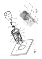
- the socket is intended to be received inside a housing 1 that includes a structural element 2 of the vehicle, dashboard or the like in particular, as schematized on the fig.1 .
- the socket is intended in particular to provide a reliable electrical connection between the plug that it receives occasionally, and terminals of an electrical circuit of the vehicle.
- the socket is mainly composed of a unitary body 3 constituting a first conductive element, and a monobloc assembly 4 which carries the unitary body 3 and a second conductive element 5.
- the unitary body 3 and the monobloc assembly 4 are assembled to each other by interlocking from cooperating members that they respectively incorporate construction.
- the second conductive element 5 consists, for example, of a plate 6 which is placed at the bottom of the monobloc assembly 4 to cooperate with the second axial connection pad of the plug, and which is provided with a tab 7 which is extends to a corresponding terminal of the circuit.
- the second conductive element 5 is advantageously attached by interlocking on the one-piece assembly 4.
- the unitary body 3 consists of a shank 8 which is extended by a first plug arranged in first tongue 9.
- the shank 8 is able to be interposed between the plug and the monoblock assembly 4 by axial reception of the socket body male, so that the unitary body 3 constitutes a connecting member both electrical and mechanical between the plug and the socket.
- the one-piece assembly 4 is obtained by molding an electrically insulating plastic material, and integrates a connector 10 and a ring 11 connecting the socket inside the housing 1 of the structural element 2.
- the connector 10 and the ring 11 are connected to each other by a cage 12 forming a spacer to provide a space for the axial passage of the body of the plug to the connector 10.
- This cage 12 is stiffened by peripheral stiffeners 13, which further constitute guides for promoting the introduction of the socket inside the housing 1.
- the ring 11 is preferably equipped with a polarizer 14, visible on the fig.1 , which is intended to cooperate with a corresponding relief 15 formed in the structural element 2.
- the assembly by interlocking between the unitary body 3 and the monobloc assembly 4 allows their relative positioning both axial and radial, to match the tongues 7.9 with the terminals of the electrical circuit.
- the one-piece assembly 4 is able to be interposed between the unitary body 3 and the housing 1, by receiving axial shaft 8 inside the ring 11 and by receiving the first tongue 9 through a first window 16 formed in the connector 10, visible on the fig.5 .
- the connector 10 also has a second window 17 passing through the second tab 7 constituting the second conductive member 5. It follows that the unitary body 3 is axially inserted and radially positioned within the one-piece assembly. The insertion stroke of the unitary body 3 inside the one-piece body is limited by axial positioning means.
- the axial positioning means consist of a fold back 18 of the first tongue 9, which is intended to be placed in abutment against the connector 10.
- the first conductive element consisting of the unitary body 3 is formed by cutting a metal sheet 19 into an orthogonal strip 20 and lamella 21. The strip 20 is rolled to form the barrel 8, while the blade 21 is folded on itself to form the first tongue 9 and its fold 18.
- the axial positioning means are obtained from a clipping assembly of the unitary body 3 on the one-piece assembly 4 between two axial opposing supports.
- One of these axial supports 22 is formed of a flange formed at the distal end of the unitary body 3 and intended to bear against the connector 10.
- the other axial support 23 is formed of a projection that includes the shaft 8 and which bears against the edge of a window 24 formed in the cage 12 in the vicinity of its zone of junction with the ring 11.
- the unitary body 3 is advantageously formed by stamping a metal blank, which makes it possible to form in a single operation the barrel 8, the axial support member 22 and the first tongue 9, or even the support member 23.
- the socket according to the present invention is obtained by overmolding the monobloc assembly 4 on the unitary body 3.
- the one-piece assembly 4 is mounted by clipping on the structural element 2 after receiving the unitary body 3, being immobilized axially between two axial axial supports.
- One of these supports 25 is formed by a flange of the ring 11, while the other support 26 is formed of reliefs formed at the periphery of the cage 12, in the vicinity of the collar 25.
- the socket is mounted on the structural element 2 being positioned radially by means of the polarizer 14 and axially being engaged on either side of the wall of the structural element 2 through which the housing 1 is formed.
Landscapes
- Details Of Connecting Devices For Male And Female Coupling (AREA)
- Connector Housings Or Holding Contact Members (AREA)
- Coupling Device And Connection With Printed Circuit (AREA)
- Motor Or Generator Frames (AREA)
Description
- La présente invention est du domaine de l'équipement automobile relatif aux connexions conductrices de l'électricité à partir d'une association structurelle de plusieurs éléments de connexion électrique isolés les uns des autres. Elle a pour objet une prise électrique femelle annexe destinée à équiper un véhicule automobile pour l'alimentation occasionnelle d'un accessoire muni d'une prise mâle complémentaire de connexion.
- Dans le domaine automobile, il est fréquent d'équiper un véhicule d'une prise électrique femelle annexe qui est disponible pour un passager en vue de l'alimentation électrique occasionnelle d'un appareil accessoire, tel qu'un appareil de téléphonie portable par exemple. D'une manière générale, de tels appareils accessoires sont munis d'une prise mâle de connexion comportant un corps de conformation globalement cylindrique, qui est porteur à sa périphérie d'un premier plot de connexion et à son extrémité distale d'un deuxième plot de connexion.
- Pour mettre en relation les plots de la prise mâle avec des bornes du circuit électrique du véhicule qui leur sont affectées, la prise femelle comporte un premier élément conducteur qui est conformé en cylindre pour sa mise en relation avec le corps de la prise mâle, ce cylindre étant prolongé par une première fiche. Un deuxième élément conducteur est conformé en platine contre laquelle prend appui le deuxième plot de la prise mâle, cette platine étant prolongée par une deuxième fiche. Les fiches sont prévues pour être mises en relation respectivement avec une borne de tension et avec une borne de masse du circuit électrique du véhicule, pour délivrer à l'appareil accessoire une tension continue de faible voltage, à titre indicatif de l'ordre de 12 V, 24 V, voire 42 V. Un connecteur électriquement isolant est placé en bout distal de la prise femelle, pour isoler électriquement les éléments conducteurs l'un par rapport à l'autre, voire pour procurer une liaison mécanique entre la prise femelle et les bornes. Par ailleurs, la prise femelle est équipée d'un organe de jonction sur un élément structurel du véhicule, tel qu'une planche de bord, console ou élément structurel analogue. Cet organe de jonction est par exemple conformé en bague destinée à être introduite à l'intérieur d'un logement que comporte à cet effet l'élément structurel. On pourra par exemple se reporter aux documents
US 5044993 (El-HAJ et al. ) etUS 4713017 (PESAPANE ) qui décrivent des prises électriques femelles annexes du genre susvisé. - Il est recherché une obtention de la prise femelle à moindre coût, notamment en simplifiant sa structure et ses modalités d'obtention. Il est souhaitable que la structure de la prise femelle permette de simplifier les opérations nécessaires pour l'assemblage des éléments qui la compose et pour son montage sur l'élément structurel du véhicule. Cette simplification de structure ne doit pas être faite au détriment de la fiabilité de la liaison électrique obtenue entre la prise mâle et les bornes, et ne doit pas affecter la robustesse du maintien de la prise femelle sur l'élément structurel du véhicule. Au regard de ces exigences, il doit notamment être pris en compte les opérations fréquentes et répétées d'introduction et de retrait de la prise mâle, et la structure de la prise femelle doit être intrinsèquement robuste, fiable et pérenne dans un tel cadre d'utilisation.
- Une prise femelle selon le preambule de la revendication 1 est décrite par le document
EP-A2 1 164 666 . - Le but de la présente invention est de proposer une prise électrique femelle destinée à équiper un véhicule automobile pour l'alimentation occasionnelle d'un accessoire équipé d'une prise mâle complémentaire de connexion. Il est plus particulièrement visé par la présente invention de proposer une telle prise femelle qui puisse être obtenue à moindre coût et être aisément installée sur un élément structurel, tout en étant robuste, fiable et pérenne.
- Le dispositif de la présente invention est une prise femelle électrique annexe selon la revendication 1 destinée à équiper un véhicule automobile, pour l'alimentation électrique occasionnelle d'un appareil accessoire équipé d'une prise mâle complémentaire de connexion.
- Plus particulièrement, le cylindre du premier élément conducteur est destiné à coopérer avec un corps de la prise mâle porteur d'un premier plot de connexion, tandis que la première fiche est destinée à coopérer avec la borne correspondante du circuit électrique du véhicule. La platine du deuxième élément conducteur est destinée à être en contact axial avec un deuxième plot de connexion porté par le corps de la prise mâle, tandis que la deuxième fiche est destinée à coopérer avec la borne du circuit électrique du véhicule qui lui est affectée. Le connecteur est agencé pour isoler électriquement les éléments conducteurs l'un de l'autre, et de préférence pour procurer une liaison mécanique entre la prise femelle et les bornes.
- Selon la présente invention, une telle prise femelle est principalement reconnaissable en ce qu'elle comporte les caractéristiques suivantes, prises isolément ou en combinaison :
- Le premier élément conducteur est constitué d'un corps unitaire composé d'un fût de réception de la prise mâle et d'emboîtement à l'intérieur de la bague, et d'une première languette de connexion constitutive de la première fiche. Le fût constitue avantageusement un organe d'interposition radiale entre la bague et la prise mâle, et est exploité pour réaliser une double fonction de jonction du corps unitaire sur la bague et d'agencement en cylindre du premier élément conducteur pour sa coopération avec la prise mâle.
- La bague et le connecteur sont intégrés dans un ensemble monobloc. L'ensemble monobloc constitue avantageusement un organe rigide d'interposition entre l'élément structurel et les bornes du circuit électrique, pour l'intégration robuste de la prise femelle sur le véhicule. En outre, lors du montage de la prise femelle sur le véhicule, son positionnement et sa liaison mécanique avec respectivement l'élément structurel et les bornes du circuit du véhicule en sont facilités.
- La prise femelle comprend des moyens d'assemblage entre le corps unitaire et l'ensemble monobloc. Ces moyens d'assemblage sont susceptibles d'être du type avantageux par emboîtement par l'intermédiaire d'organes d'assemblage coopérants respectivement intégrés dans le corps unitaire et l'ensemble monobloc. Plus particulièrement, la répartition des organes nécessaires à la composition de la prise femelle entre deux organes cohésifs respectivement constitués par le corps unitaire et par l'ensemble monobloc, permet d'organiser leur assemblage aisé par emboîtement au moyen d'organes d'assemblage coopérants qu'ils intègrent respectivement de construction. Il en ressort que les moyens d'assemblage sont obtenus à moindre coût et rendent les modalités d'assemblage des composants de la prise femelle rapides et aisées à mettre en oeuvre.
- La prise femelle proposée par l'invention est avantageusement composée d'un nombre restreint d'éléments assemblés entre eux, et notamment du corps unitaire, de l'ensemble monobloc et du deuxième élément conducteur. L'assemblage de ces éléments entre eux et le montage de la prise femelle sur l'élément structurel du véhicule, peuvent être réalisés par emboîtement à partir de leur structure propre, sans faire appel à des organes d'assemblage rapportés.
- Ces dispositions sont telles que les opérations d'assemblage de la prise femelle et de son montage sur l'élément structurel en sont simplifiées, la prise femelle étant apte à être essentiellement composée du corps unitaire et de l'ensemble monobloc, qui intègrent de construction des organes d'emboîtement pour leur assemblage l'un à l'autre et pour le montage de la prise femelle sur l'élément structurel du véhicule. Le deuxième élément conducteur peut être structurellement réduit à la platine et la deuxième fiche conjointement formées à partir d'une même feuille de métal, en étant rapporté par emboîtement sur le connecteur qui comporte un relief d'emboîtement prévu à cet effet. Ces dispositions sont aussi telles que la mise en position relative entre les bornes du circuit électrique du véhicule et les plots de la prise mâle, est aisément obtenue de manière rigoureuse à partir des moyens d'assemblage du corps unitaire et de l'ensemble monobloc l'un à l'autre. Ces moyens d'assemblage intègrent de préférence des moyens de positionnement radial et des moyens de mise en butée axiale du corps unitaire sur l'ensemble monobloc lors de leur emboîtement l'un à l'autre, de manière à positionner les fiches en correspondance avec les bornes. La mise en relation entre la prise mâle et les bornes est obtenue à moindre coût de manière simple et aisée, avec une robustesse offerte par le caractère rigide de l'ensemble monobloc interposé entre l'élément structurel et les bornes, et avec un positionnement relatif fiable entre la prise mâle et les bornes à partir des moyens d'assemblage.
- L'ensemble monobloc est avantageusement apte à être formé par moulage d'un matériau plastique électriquement isolant. La décomposition proposée de la structure de la prise femelle en un corps unitaire ef en un ensemble monobloc permet de réaliser la bague et le connecteur en une opération unique de moulage à moindre coût, et permet d'éviter des opérations de montage à partir de l'intégration des organes nécessaires à leur assemblage l'un à l'autre. La mise en relation entre la prise mâle et les bornes est non seulement rendue mécaniquement robuste, mais aussi est électriquement fiabilisée en écartant tout risque de mise en relation électrique inadéquate.
- Les moyens d'assemblage sont avantageusement du type par emboîtement axial du corps unitaire à l'intérieur de l'ensemble monobloc, et associent des moyens de positionnement radial et des moyens de positionnement axial du corps unitaire par rapport à l'ensemble monobloc.
- Les moyens de positionnement radial sont avantageusement constitués d'une première fenêtre ménagée dans le connecteur pour l'emboîtement de la première languette. Cette première fenêtre est notamment radialement décalée par rapport à l'axe d'emboîtement du corps unitaire à l'intérieur de l'ensemble monobloc.
- Les moyens de positionnement axial du corps unitaire à l'intérieur de l'ensemble monobloc sont plus particulièrement des moyens de limitation de la course d'introduction axiale du corps unitaire vers l'intérieur de l'ensemble monobloc, qui sont accessoirement complétés par un appui axial antagoniste du corps unitaire sur l'ensemble monobloc.
- Selon une première forme de réalisation des moyens de positionnement axial, ceux-ci sont constitués d'un montage par clipage du corps unitaire sur l'ensemble monobloc entre deux appuis axiaux antagonistes. Ces appuis axiaux antagonistes sont notamment constitués par des organes de jonction coopérants qui sont respectivement intégrés au corps unitaire et à l'ensemble monobloc. Par exemple, le corps unitaire prend axialement appui par son fond contre le connecteur et intègre un clip ou organe analogue de prise d'appui antagoniste contre l'ensemble monobloc, tel que contre la tranche d'une fenêtre que comporte ce dernier par exemple.
- Selon une deuxième forme de réalisation des moyens de positionnement axial, ceux-ci sont constitués d'un repli que comporte la première languette pour sa prise d'appui axiale contre le connecteur. Accessoirement, le connecteur intègre un relief de réception de ce repli pour conforter son appui en fond du connecteur.
- Selon une forme préférée de réalisation de l'ensemble monobloc, celui-ci comprend une cage formée d'un prolongement de la bague jusqu'au connecteur. Plus particulièrement, cette cage ménage un espace pour le passage de la prise mâle vers le connecteur, voire aussi enveloppe le corps unitaire pour le protéger et éviter son contact électrique inopportun avec des éléments environnant la prise femelle installée sur l'élément structurel. Une telle cage est aussi susceptible d'être avantageusement exploitée pour un assemblage par emboîtement élastique (clipage) entre le corps unitaire et l'ensemble monobloc, voire aussi entre l'ensemble monobloc et l'élément structurel du véhicule.
- La cage et/ou le corps unitaire sont de préférence élastiquement déformables sous l'effet de l'introduction du corps unitaire à l'intérieur de l'ensemble monobloc, pour un montage en emboîtement élastique étroit du corps unitaire à l'intérieur de l'ensemble monobloc. L'ensemble monobloc étant avantageusement obtenu par moulage d'une matière plastique, celui-ci peut aisément intégrer divers organes annexes, notamment pour conforter sa robustesse et son guidage à l'intérieur du logement de l'élément structurel.
- Par exemple, la cage est avantageusement munie de raidisseurs axiaux formant en outre des rampes de guidage pour l'introduction de l'ensemble monobloc à l'intérieur du logement de l'élément structurel.
- Le deuxième élément conducteur est rapporté par emboîtement sur le connecteur. Par exemple, une deuxième languette constitutive de la deuxième fiche est introduite à travers une deuxième fenêtre que comporte le connecteur, tandis que la platine est placée en fond intérieur de l'ensemble monobloc. Cette fenêtre est susceptible d'être indifféremment orientée coaxialement ou de manière radialement décalée par rapport à l'axe d'emboîtement du corps unitaire à l'intérieur de l'ensemble monobloc
- De préférence, l'ensemble monobloc est doté d'un détrompeur pour le positionnement radial de la prise femelle sur l'élément structurel et la mise en correspondance rigoureuse des languettes avec les bornes.
- De préférence encore, l'ensemble monobloc est monté par clipage sur l'élément structurel entre deux appuis axiaux antagonistes. Ces appuis axiaux antagonistes sont notamment constitués par une prise d'appui axial de l'ensemble monobloc de part et d'autre d'une paroi de l'élément structurel comportant le logement de réception de la prise femelle.
- Par exemple, la bague est épaulée pour son introduction et sa prise d'appui en face avant de la paroi, tandis que la cage comporte, préférentiellement au voisinage de sa zone de jonction avec la bague, des reliefs d'appuis axiaux antagonistes contre la face arrière de la paroi. Il en ressort une installation rapide, aisée, fiable et pérenne de la prise femelle sur l'élément structurel du véhicule, à partir de la face avant de ce dernier.
- Il est aussi proposé par la présente invention un procédé d'obtention d'un premier élément conducteur constitutif d'une prise femelle.
- Selon l'invention, le premier élément conducteur est obtenu à partir d'une opération unique d'emboutissage d'un flan métallique, pour la formation concomitante du fût, de la première languette et d'un rebord d'appui axial du corps unitaire contre le connecteur.
- Selon un autre exemple de réalisation ne faisant pas partie de l'invention, le premier élément conducteur est obtenu à partir d'une opération de découpage d'un feuillard ménageant orthogonalement un bandeau et une lamelle. Cette opération de découpage est suivie d'une opération de mise en forme à plat du feuillard découpé, visant à rouler le bandeau pour former le fût et à plier sur elle-même la lamelle pour former la première languette et son repli.
- La présente invention sera mieux comprise, et des détails en relevant apparaîtront, à la lecture de la description qui va en être faite d'exemples de réalisation en relation avec les figures des planches annexées, dans lesquelles :
- La
fig.1 est une illustration en perspective éclatée d'une prise femelle selon une variante de réalisation ne faisant pas partie de l'invention. - La
fig.2 est une illustration en perspective d'un procédé d'obtention d'un élément conducteur constitutif de la prise femelle représentée sur lafig.1 . - Les
fig.3 à fig.5 sont des illustrations d'une prise femelle de la présente invention, respectivement en perspective éclatée, en perspective assemblée et en perspective vue de bout. - La
fig.6 est une illustration en perspective d'un élément conducteur constitutif de la prise femelle représentée sur lesfig.3 à fig.5 . - Sur la
fig.1 , et sur lesfig.3 à fig.5 , une prise femelle est destinée à équiper un véhicule pour l'alimentation occasionnelle en énergie électrique d'un accessoire. Un tel accessoire est communément équipé d'une prise mâle comprenant un corps cylindrique muni d'un premier plot de connexion périphérique et d'un deuxième plot de connexion axiale. La prise femelle est destinée à être reçue à l'intérieur d'un logement 1 que comporte un élément structurel 2 du véhicule, planche de bord ou analogue notamment, tel que schématisé sur lafig.1 . La prise femelle est notamment destinée à procurer une liaison électrique fiable entre la prise mâle qu'elle reçoit occasionnellement, et des bornes d'un circuit électrique du véhicule. - La prise femelle est principalement composée d'un corps unitaire 3 constitutif d'un premier élément conducteur, et d'un ensemble monobloc 4 qui est porteur du corps unitaire 3 et d'un deuxième élément conducteur 5. Le corps unitaire 3 et l'ensemble monobloc 4 sont assemblés entre eux par emboîtement à partir d'organes coopérants qu'ils intègrent respectivement de construction. Le deuxième élément conducteur 5 est par exemple constitué d'une platine 6 qui est placée en fond de l'ensemble monobloc 4 pour coopérer avec le deuxième plot de connexion axial de la prise mâle, et qui est munie d'une languette 7 qui s'étend vers une borne correspondante du circuit. Le deuxième élément conducteur 5 est avantageusement rapporté par emboîtement sur l'ensemble monobloc 4.
- Le corps unitaire 3 est constitué d'un fût 8 qui est prolongé par une première fiche agencée en première languette 9. Le fût 8 est apte à être interposé entre la prise mâle et l'ensemble monobloc 4 par réception axiale du corps de la prise mâle, de sorte que le corps unitaire 3 constitue un organe de liaison à la fois électrique et mécanique entre la prise mâle et la prise femelle.
- L'ensemble monobloc 4 est obtenu par moulage d'une matière plastique électriquement isolante, et intègre un connecteur 10 et une bague 11 de jonction de la prise femelle à l'intérieur du logement 1 de l'élément structurel 2. Le connecteur 10 et la bague 11 sont reliés l'un à l'autre par une cage 12 formant entretoise pour ménager un espace en vue du passage axial du corps de la prise mâle vers le connecteur 10. Cette cage 12 est rigidifiée par des raidisseurs 13 périphériques, qui constituent en outre des guides pour favoriser l'introduction de la prise femelle à l'intérieur du logement 1. La bague 11 est de préférence équipée d'un détrompeur 14, visible sur la
fig.1 , qui est destiné à coopérer avec un relief correspondant 15 ménagé dans l'élément structurel 2. Ces dispositions visent à obtenir un positionnement radial aisé de la prise femelle sur l'élément structurel 2. - L'assemblage par emboîtement entre le corps unitaire 3 et l'ensemble monobloc 4 permet leur positionnement relatif tant axial que radial, pour mettre en correspondance les languettes 7,9 avec les bornes du circuit électrique. L'ensemble monobloc 4 est apte à être interposé entre le corps unitaire 3 et le logement 1, par réception axiale du fût 8 à l'intérieur de la bague 11 et par réception de la première languette 9 à travers une première fenêtre 16 ménagée dans le connecteur 10, visible sur la
fig.5 . Le connecteur 10 comporte aussi une deuxième fenêtre 17 de passage à son travers de la deuxième languette 7 constitutive du deuxième élément conducteur 5. Il en ressort que le corps unitaire 3 est axialement introduit et radialement positionné à l'intérieur de l'ensemble monobloc. La course d'introduction du corps unitaire 3 à l'intérieur du corps monobloc est limitée par des moyens de positionnement axial. - Sur la variante de réalisation illustrée sur la
fig.1 ne faisant pas partie de l'invention, les moyens de positionnement axial sont constitués d'un repli 18 de la première languette 9, qui est destiné à être placé en butée contre le connecteur 10. En se reportant sur lafig.2 , le premier élément conducteur constitué du corps unitaire 3 est formé par découpage d'une feuille de métal 19 en bandeau 20 et lamelle 21 orthogonaux. Le bandeau 20 est roulé pour former le fût 8, tandis que la lamelle 21 est repliée sur elle-même pour former la première languette 9 et son repli 18. - Sur la variante de réalisation illustrée sur les
fig.3 à fig.5 , les moyens de positionnement axial sont obtenus à partir d'un montage par clipage du corps unitaire 3 sur l'ensemble monobloc 4 entre deux appuis axiaux antagonistes. L'un de ces appuis axiaux 22 est formé d'un rebord ménagé au bout distal du corps unitaire 3 et destiné à prendre appui contre le connecteur 10. L'autre appui axial 23 est formé d'une saillie que comporte le fût 8 et qui prend appui contre la tranche d'une fenêtre 24 ménagée dans la cage 12 au voisinage de sa zone de jonction avec la bague 11. Sur lafig.6 , le corps unitaire 3 est avantageusement formé par emboutissage d'un flan métallique, qui permet de former en une même opération le fût 8, l'organe d'appui axial 22 et la première languette 9, voire aussi l'organe d'appui 23. - Dans une variante non représentée, la prise femelle selon la présente invention est obtenue par surmoulage de l'ensemble monobloc 4 sur le corps unitaire 3.
- L'ensemble monobloc 4 est monté par clipage sur l'élément structurel 2 après réception du corps unitaire 3, en étant immobilisé axialement entre deux appuis axiaux antagonistes. L'un de ces appuis 25 est formé par une collerette de la bague 11, tandis que l'autre appui 26 est formé de reliefs ménagés en périphérie de la cage 12, au voisinage de la collerette 25. Il en ressort que la prise femelle est montée sur l'élément structurel 2 en étant positionnée radialement au moyen du détrompeur 14, et axialement en étant en prise de part et d'autre de la paroi de l'élément structurel 2 à travers laquelle est ménagé le logement 1.
Claims (12)
- Prise femelle électrique annexe destinée à équiper un véhicule automobile, pour l'alimentation électrique occasionnelle d'un appareil accessoire équipé d'une prise mâle complémentaire de connexion, cette prise femelle comprenant :*) une bague (11) de jonction de la prise femelle à l'intérieur d'un logement (1) que comporte un élément structurel (2) du véhicule,*) un connecteur (10) placé en fond de la prise femelle pour l'emboîtement de cette dernière sur les bornes d'un circuit électrique du véhicule, et*) un couple d'éléments conducteurs pour la liaison électrique entre des plots de connexion de la prise mâle et lesdites bornes qui leur sont affectées, dont un premier élément conducteur conformé en cylindre prolongé d'une première fiche et dont un deuxième élément conducteur (5) conformé en platine (6) pro-longée par une deuxième fiche, dans laquelle :le premier élément conducteur est constitué d'un corps unitaire (3) composé d'un fût (8) de réception de la prise mâle et d'emboîtement à l'intérieur de la bague (11), et d'une première languette (9) de connexion constitutive de la première fiche,la bague (11) et le connecteur (10) étant intégrés dans un ensemble monobloc (4),des moyens d'assemblage entre le corps unitaire (3) et l'ensemble monobloc (4) étant prévus, caractérisée en ce quele corps unitaire (3) est formé par emboutissage d'un flan métallique, qui permet de former en une même opération le fût (8), un organe d'appui axial (22) et la première languette (9).
- Prise femelle selon la revendication 1, caractérisée en ce que l'ensemble monobloc (4) est formé par moulage d'un matériau électriquement Isolant.
- Prise femelle selon la revendication 2, caractérisé en ce que le matériau électriquement isolant est un matériau plastique.
- Prise femelle selon l'une quelconque des revendications précédentes, caractérisée en ce que les moyens d'assemblage sont avantageusement du type par emboîtement axial du corps unitaire (3) à l'intérieur de l'ensemble monobloc (4), et associent des moyens de positionnement radial et des moyens de positionnement axial du corps unitaire (3) par rapport à l'ensemble monobloc (4).
- Prise femelle selon l'une quelconque des revendications 1 à 4, caractérisée en ce que les moyens d'assemblage sont avantageusement constitués par un surmoulage de l'ensemble monobloc (4) sur le corps unitaire (3).
- Prise femelle selon la revendication 4 ou la revendication 5, caractérisée en ce que les moyens de positionnement radial sont constitués d'une première fenêtre (16) ménagée dans le connecteur (10) pour l'emboîtement de la première languette (9).
- Prise femelle selon l'une quelconque des revendications 4 à 6, caractérisée en ce que les moyens de positionnement axial sont des moyens de limitation de la course d'introduction axiale du corps unitaire (3) vers l'intérieur de l'ensemble monobloc (4), qui sont accessoirement complétés par un appui axial antagoniste (22, 23) du corps unitaire (3) sur l'ensemble monobloc (4).
- Prise femelle selon l'une quelconque des revendications précédentes, caractérisée en ce que l'ensemble monobloc (4) comprend une cage (12) formée d'un prolongement de la bague (11) Jusqu'au connecteur (10).
- Prise femelle selon la revendication 8, caractérisée en ce que la cage (12) est munie de raidisseurs (13) axiaux formant des rampes de guidage pour l'introduction de l'ensemble monobloc (4) à l'intérieur du logement (1) de l'élément structurel (2).
- Prise femelle selon l'une quelconque des revendications précédentes, caractérisée en ce que le deuxième élément conducteur (5) est rapporté par emboîtement sur le connecteur (10), la deuxième fiche étant introduite à travers une deuxième fenêtre (17) que comporte le connecteur (10), tandis que la platine (6) est placée en fond intérieur de l'ensemble monobloc (4).
- Prise électrique femelle selon l'une quelconque des revendications précédentes, caractérisée en ce que l'ensemble monobloc (4) est doté d'un détrompeur (14) pour le positionnement radial de la prise femelle sur l'élément structurel (2) et la mise en correspondance des languettes (7,9) avec les bornes.
- Prise femelle selon l'une quelconque des revendications précédentes, caractérisée en ce que l'ensemble monobloc (4) est monté par clipage sur l'élément structurel (2) entre deux appuis axiaux antagonistes (25,26).
Applications Claiming Priority (2)
| Application Number | Priority Date | Filing Date | Title |
|---|---|---|---|
| FR0701633A FR2913542A1 (fr) | 2007-03-06 | 2007-03-06 | Prise femelle electrique annexe pour vehicule automobile |
| PCT/EP2008/052390 WO2008107354A1 (fr) | 2007-03-06 | 2008-02-27 | Prise femelle electrique annexe pour vehicule automobile |
Publications (2)
| Publication Number | Publication Date |
|---|---|
| EP2127043A1 EP2127043A1 (fr) | 2009-12-02 |
| EP2127043B1 true EP2127043B1 (fr) | 2016-01-06 |
Family
ID=38254943
Family Applications (1)
| Application Number | Title | Priority Date | Filing Date |
|---|---|---|---|
| EP08709236.7A Active EP2127043B1 (fr) | 2007-03-06 | 2008-02-27 | Prise femelle electrique annexe pour vehicule automobile |
Country Status (7)
| Country | Link |
|---|---|
| US (1) | US8215999B2 (fr) |
| EP (1) | EP2127043B1 (fr) |
| JP (1) | JP5160571B2 (fr) |
| CN (1) | CN101636883A (fr) |
| ES (1) | ES2565461T3 (fr) |
| FR (1) | FR2913542A1 (fr) |
| WO (1) | WO2008107354A1 (fr) |
Families Citing this family (4)
| Publication number | Priority date | Publication date | Assignee | Title |
|---|---|---|---|---|
| US9099801B2 (en) | 2013-11-22 | 2015-08-04 | Casco Products Corporation | Short circuit protection for electric cigar lighter and power outlet sockets |
| FR3031419A1 (fr) * | 2015-01-06 | 2016-07-08 | Valeo Vision | Prise de courant pour habitacle de vehicule |
| FR3033215B1 (fr) * | 2015-02-26 | 2017-02-24 | Valeo Vision | Prise de courant pour habitacle de vehicule |
| US9887498B2 (en) * | 2016-01-08 | 2018-02-06 | Casco Products Corporation | Compact protection device for automotive cigar lighter and power outlet |
Family Cites Families (10)
| Publication number | Priority date | Publication date | Assignee | Title |
|---|---|---|---|---|
| SE419491B (sv) * | 1979-12-05 | 1981-08-03 | Bo Strandfeldt | Honkontaktdon |
| JPH0140140Y2 (fr) | 1985-05-13 | 1989-12-01 | ||
| US4713017A (en) * | 1986-10-10 | 1987-12-15 | Casco Products Corporation | Electrical power receptacle |
| US5044993A (en) | 1990-09-10 | 1991-09-03 | Casco Products Corporation | Power outlet for electrical accessories |
| US5230641A (en) * | 1992-08-06 | 1993-07-27 | Safco Corporation | Electrical receptacle |
| DE4436794C2 (de) * | 1994-10-14 | 1997-01-02 | Schoeller & Co Elektrotech | Gerätesteckdose für Kraftfahrzeuge |
| JP2001357947A (ja) | 2000-06-12 | 2001-12-26 | Niles Parts Co Ltd | 車両用ソケット |
| FR2858684B1 (fr) * | 2003-08-07 | 2005-10-21 | Valeo Vision | Bouchon chauffant d'allume-cigare electrique et agencement d'un allume-cigare comportant ce bouchon |
| FR2859954B1 (fr) * | 2003-09-19 | 2005-11-11 | Valeo Vision | Dispositif d'eclairage pour allume-cigare ou prise electrique multi-fonction |
| KR101047751B1 (ko) * | 2009-12-03 | 2011-07-07 | 기아자동차주식회사 | 시가 라이터 플러그 |
-
2007
- 2007-03-06 FR FR0701633A patent/FR2913542A1/fr active Pending
-
2008
- 2008-02-27 CN CN200880006401A patent/CN101636883A/zh active Pending
- 2008-02-27 EP EP08709236.7A patent/EP2127043B1/fr active Active
- 2008-02-27 US US12/529,059 patent/US8215999B2/en active Active
- 2008-02-27 JP JP2009552172A patent/JP5160571B2/ja active Active
- 2008-02-27 WO PCT/EP2008/052390 patent/WO2008107354A1/fr not_active Ceased
- 2008-02-27 ES ES08709236.7T patent/ES2565461T3/es active Active
Also Published As
| Publication number | Publication date |
|---|---|
| EP2127043A1 (fr) | 2009-12-02 |
| FR2913542A1 (fr) | 2008-09-12 |
| US8215999B2 (en) | 2012-07-10 |
| WO2008107354A1 (fr) | 2008-09-12 |
| JP2010520595A (ja) | 2010-06-10 |
| ES2565461T3 (es) | 2016-04-04 |
| CN101636883A (zh) | 2010-01-27 |
| JP5160571B2 (ja) | 2013-03-13 |
| US20120094543A1 (en) | 2012-04-19 |
Similar Documents
| Publication | Publication Date | Title |
|---|---|---|
| US7928628B2 (en) | Electric motor having terminal connectable with external connector | |
| EP1800372B1 (fr) | Dispositif de verrouillage d'elements de connecteur et connecteur le comprenant | |
| US20210351539A1 (en) | Male connector and connector device | |
| US20090178845A1 (en) | Electrical connector assembly with enhanced grounding | |
| EP3192711B1 (fr) | Embout d'extrémité pour un balai d'essuie-glace de véhicule | |
| EP2127043A1 (fr) | Prise femelle electrique annexe pour vehicule automobile | |
| EP2859631A1 (fr) | Plaque de finition equipee de moyens de centrage sur un element interne d'un appareillage electrique | |
| EP2727190B1 (fr) | Dispositif de raccordement electrique d'un compresseur electrique | |
| EP3614817B1 (fr) | Ensemble électrique | |
| FR3125175A1 (fr) | Passe-câble étanche d'un connecteur enfichable | |
| EP0434519B1 (fr) | Allume-cigare, notamment pour véhicules automobiles | |
| CN105745124A (zh) | 用于电点烟器和电源插座的短路保护 | |
| JP6197551B2 (ja) | 給電用コネクタ | |
| EP2517316B1 (fr) | Dispositif de connexion pour alimenter un equipement electrique | |
| FR2959364A1 (fr) | Ensemble porte-balais pour machine electrique, telle qu'un demarreur de vehicule automobile, cassette associee, et machine electrique pourvue d'un tel ensemble | |
| EP3321129B1 (fr) | Dispositif de montage sans vis d'un boitier de commande de projecteur sur ledit projecteur | |
| EP2917973A1 (fr) | Dispositif de raccordement électrique pour compresseur et compresseur comprenant un tel dispositif | |
| EP1961081A1 (fr) | Contact electrique a dispositif de detrompage | |
| EP2313951A2 (fr) | Dispositif a balais pour demarreur de vehicule automobile | |
| EP2020734A1 (fr) | Capot de protection destiné à être fixé par encliquetage sur un flasque d'une machine électrique tournante et machine électrique tournante comportant un tel capot | |
| FR2769410A1 (fr) | Bloc de contact pour socle de prise de courant | |
| EP1751827B1 (fr) | Accessoire de denudage d'un conducteur electrique isole et borne de connexion auto-denudante comprenant un tel accessoire | |
| FR3053845A1 (fr) | Procedes de fabrication et de connexion d'un connecteur | |
| EP4627679A1 (fr) | Prise de chargement électrique avec organe anti-électrisation | |
| JP2556298Y2 (ja) | 自動車用シガーライター用電源取出プラグ |
Legal Events
| Date | Code | Title | Description |
|---|---|---|---|
| PUAI | Public reference made under article 153(3) epc to a published international application that has entered the european phase |
Free format text: ORIGINAL CODE: 0009012 |
|
| 17P | Request for examination filed |
Effective date: 20091002 |
|
| AK | Designated contracting states |
Kind code of ref document: A1 Designated state(s): AT BE BG CH CY CZ DE DK EE ES FI FR GB GR HR HU IE IS IT LI LT LU LV MC MT NL NO PL PT RO SE SI SK TR |
|
| 17Q | First examination report despatched |
Effective date: 20100118 |
|
| DAX | Request for extension of the european patent (deleted) | ||
| REG | Reference to a national code |
Ref country code: DE Ref legal event code: R079 Ref document number: 602008041792 Country of ref document: DE Free format text: PREVIOUS MAIN CLASS: H01R0024020000 Ipc: B60Q0003020000 |
|
| GRAP | Despatch of communication of intention to grant a patent |
Free format text: ORIGINAL CODE: EPIDOSNIGR1 |
|
| RIC1 | Information provided on ipc code assigned before grant |
Ipc: H01R 103/00 20060101ALI20150728BHEP Ipc: H01R 43/16 20060101ALI20150728BHEP Ipc: H01R 13/74 20060101ALI20150728BHEP Ipc: F23Q 7/00 20060101ALI20150728BHEP Ipc: H01R 13/50 20060101ALI20150728BHEP Ipc: H01R 13/42 20060101ALI20150728BHEP Ipc: B60Q 3/02 20060101AFI20150728BHEP Ipc: H01R 43/20 20060101ALI20150728BHEP Ipc: H01R 24/38 20110101ALI20150728BHEP |
|
| INTG | Intention to grant announced |
Effective date: 20150814 |
|
| GRAS | Grant fee paid |
Free format text: ORIGINAL CODE: EPIDOSNIGR3 |
|
| GRAA | (expected) grant |
Free format text: ORIGINAL CODE: 0009210 |
|
| AK | Designated contracting states |
Kind code of ref document: B1 Designated state(s): AT BE BG CH CY CZ DE DK EE ES FI FR GB GR HR HU IE IS IT LI LT LU LV MC MT NL NO PL PT RO SE SI SK TR |
|
| REG | Reference to a national code |
Ref country code: GB Ref legal event code: FG4D Free format text: NOT ENGLISH |
|
| REG | Reference to a national code |
Ref country code: CH Ref legal event code: EP |
|
| REG | Reference to a national code |
Ref country code: IE Ref legal event code: FG4D Free format text: LANGUAGE OF EP DOCUMENT: FRENCH |
|
| REG | Reference to a national code |
Ref country code: AT Ref legal event code: REF Ref document number: 768567 Country of ref document: AT Kind code of ref document: T Effective date: 20160215 |
|
| REG | Reference to a national code |
Ref country code: DE Ref legal event code: R096 Ref document number: 602008041792 Country of ref document: DE |
|
| REG | Reference to a national code |
Ref country code: FR Ref legal event code: PLFP Year of fee payment: 9 |
|
| REG | Reference to a national code |
Ref country code: ES Ref legal event code: FG2A Ref document number: 2565461 Country of ref document: ES Kind code of ref document: T3 Effective date: 20160404 |
|
| REG | Reference to a national code |
Ref country code: NL Ref legal event code: FP |
|
| REG | Reference to a national code |
Ref country code: LT Ref legal event code: MG4D |
|
| REG | Reference to a national code |
Ref country code: AT Ref legal event code: MK05 Ref document number: 768567 Country of ref document: AT Kind code of ref document: T Effective date: 20160106 |
|
| PG25 | Lapsed in a contracting state [announced via postgrant information from national office to epo] |
Ref country code: BE Free format text: LAPSE BECAUSE OF NON-PAYMENT OF DUE FEES Effective date: 20160229 |
|
| PG25 | Lapsed in a contracting state [announced via postgrant information from national office to epo] |
Ref country code: HR Free format text: LAPSE BECAUSE OF FAILURE TO SUBMIT A TRANSLATION OF THE DESCRIPTION OR TO PAY THE FEE WITHIN THE PRESCRIBED TIME-LIMIT Effective date: 20160106 Ref country code: GR Free format text: LAPSE BECAUSE OF FAILURE TO SUBMIT A TRANSLATION OF THE DESCRIPTION OR TO PAY THE FEE WITHIN THE PRESCRIBED TIME-LIMIT Effective date: 20160407 Ref country code: FI Free format text: LAPSE BECAUSE OF FAILURE TO SUBMIT A TRANSLATION OF THE DESCRIPTION OR TO PAY THE FEE WITHIN THE PRESCRIBED TIME-LIMIT Effective date: 20160106 Ref country code: NO Free format text: LAPSE BECAUSE OF FAILURE TO SUBMIT A TRANSLATION OF THE DESCRIPTION OR TO PAY THE FEE WITHIN THE PRESCRIBED TIME-LIMIT Effective date: 20160406 |
|
| PG25 | Lapsed in a contracting state [announced via postgrant information from national office to epo] |
Ref country code: LT Free format text: LAPSE BECAUSE OF FAILURE TO SUBMIT A TRANSLATION OF THE DESCRIPTION OR TO PAY THE FEE WITHIN THE PRESCRIBED TIME-LIMIT Effective date: 20160106 Ref country code: LV Free format text: LAPSE BECAUSE OF FAILURE TO SUBMIT A TRANSLATION OF THE DESCRIPTION OR TO PAY THE FEE WITHIN THE PRESCRIBED TIME-LIMIT Effective date: 20160106 Ref country code: SE Free format text: LAPSE BECAUSE OF FAILURE TO SUBMIT A TRANSLATION OF THE DESCRIPTION OR TO PAY THE FEE WITHIN THE PRESCRIBED TIME-LIMIT Effective date: 20160106 Ref country code: AT Free format text: LAPSE BECAUSE OF FAILURE TO SUBMIT A TRANSLATION OF THE DESCRIPTION OR TO PAY THE FEE WITHIN THE PRESCRIBED TIME-LIMIT Effective date: 20160106 Ref country code: IS Free format text: LAPSE BECAUSE OF FAILURE TO SUBMIT A TRANSLATION OF THE DESCRIPTION OR TO PAY THE FEE WITHIN THE PRESCRIBED TIME-LIMIT Effective date: 20160506 Ref country code: PT Free format text: LAPSE BECAUSE OF FAILURE TO SUBMIT A TRANSLATION OF THE DESCRIPTION OR TO PAY THE FEE WITHIN THE PRESCRIBED TIME-LIMIT Effective date: 20160506 Ref country code: PL Free format text: LAPSE BECAUSE OF FAILURE TO SUBMIT A TRANSLATION OF THE DESCRIPTION OR TO PAY THE FEE WITHIN THE PRESCRIBED TIME-LIMIT Effective date: 20160106 |
|
| REG | Reference to a national code |
Ref country code: CH Ref legal event code: PL |
|
| REG | Reference to a national code |
Ref country code: DE Ref legal event code: R097 Ref document number: 602008041792 Country of ref document: DE |
|
| PG25 | Lapsed in a contracting state [announced via postgrant information from national office to epo] |
Ref country code: LI Free format text: LAPSE BECAUSE OF NON-PAYMENT OF DUE FEES Effective date: 20160229 Ref country code: DK Free format text: LAPSE BECAUSE OF FAILURE TO SUBMIT A TRANSLATION OF THE DESCRIPTION OR TO PAY THE FEE WITHIN THE PRESCRIBED TIME-LIMIT Effective date: 20160106 Ref country code: EE Free format text: LAPSE BECAUSE OF FAILURE TO SUBMIT A TRANSLATION OF THE DESCRIPTION OR TO PAY THE FEE WITHIN THE PRESCRIBED TIME-LIMIT Effective date: 20160106 Ref country code: MC Free format text: LAPSE BECAUSE OF FAILURE TO SUBMIT A TRANSLATION OF THE DESCRIPTION OR TO PAY THE FEE WITHIN THE PRESCRIBED TIME-LIMIT Effective date: 20160106 Ref country code: CH Free format text: LAPSE BECAUSE OF NON-PAYMENT OF DUE FEES Effective date: 20160229 |
|
| PLBE | No opposition filed within time limit |
Free format text: ORIGINAL CODE: 0009261 |
|
| STAA | Information on the status of an ep patent application or granted ep patent |
Free format text: STATUS: NO OPPOSITION FILED WITHIN TIME LIMIT |
|
| REG | Reference to a national code |
Ref country code: DE Ref legal event code: R079 Ref document number: 602008041792 Country of ref document: DE Free format text: PREVIOUS MAIN CLASS: B60Q0003020000 Ipc: B60Q0003200000 |
|
| PG25 | Lapsed in a contracting state [announced via postgrant information from national office to epo] |
Ref country code: RO Free format text: LAPSE BECAUSE OF FAILURE TO SUBMIT A TRANSLATION OF THE DESCRIPTION OR TO PAY THE FEE WITHIN THE PRESCRIBED TIME-LIMIT Effective date: 20160106 Ref country code: SK Free format text: LAPSE BECAUSE OF FAILURE TO SUBMIT A TRANSLATION OF THE DESCRIPTION OR TO PAY THE FEE WITHIN THE PRESCRIBED TIME-LIMIT Effective date: 20160106 Ref country code: CZ Free format text: LAPSE BECAUSE OF FAILURE TO SUBMIT A TRANSLATION OF THE DESCRIPTION OR TO PAY THE FEE WITHIN THE PRESCRIBED TIME-LIMIT Effective date: 20160106 |
|
| REG | Reference to a national code |
Ref country code: IE Ref legal event code: MM4A |
|
| 26N | No opposition filed |
Effective date: 20161007 |
|
| PG25 | Lapsed in a contracting state [announced via postgrant information from national office to epo] |
Ref country code: IE Free format text: LAPSE BECAUSE OF NON-PAYMENT OF DUE FEES Effective date: 20160227 |
|
| PG25 | Lapsed in a contracting state [announced via postgrant information from national office to epo] |
Ref country code: SI Free format text: LAPSE BECAUSE OF FAILURE TO SUBMIT A TRANSLATION OF THE DESCRIPTION OR TO PAY THE FEE WITHIN THE PRESCRIBED TIME-LIMIT Effective date: 20160106 Ref country code: BG Free format text: LAPSE BECAUSE OF FAILURE TO SUBMIT A TRANSLATION OF THE DESCRIPTION OR TO PAY THE FEE WITHIN THE PRESCRIBED TIME-LIMIT Effective date: 20160406 |
|
| REG | Reference to a national code |
Ref country code: FR Ref legal event code: PLFP Year of fee payment: 10 |
|
| PG25 | Lapsed in a contracting state [announced via postgrant information from national office to epo] |
Ref country code: MT Free format text: LAPSE BECAUSE OF FAILURE TO SUBMIT A TRANSLATION OF THE DESCRIPTION OR TO PAY THE FEE WITHIN THE PRESCRIBED TIME-LIMIT Effective date: 20160106 |
|
| REG | Reference to a national code |
Ref country code: FR Ref legal event code: PLFP Year of fee payment: 11 |
|
| PG25 | Lapsed in a contracting state [announced via postgrant information from national office to epo] |
Ref country code: HU Free format text: LAPSE BECAUSE OF FAILURE TO SUBMIT A TRANSLATION OF THE DESCRIPTION OR TO PAY THE FEE WITHIN THE PRESCRIBED TIME-LIMIT; INVALID AB INITIO Effective date: 20080227 Ref country code: CY Free format text: LAPSE BECAUSE OF FAILURE TO SUBMIT A TRANSLATION OF THE DESCRIPTION OR TO PAY THE FEE WITHIN THE PRESCRIBED TIME-LIMIT Effective date: 20160106 |
|
| PG25 | Lapsed in a contracting state [announced via postgrant information from national office to epo] |
Ref country code: LU Free format text: LAPSE BECAUSE OF NON-PAYMENT OF DUE FEES Effective date: 20160227 Ref country code: TR Free format text: LAPSE BECAUSE OF FAILURE TO SUBMIT A TRANSLATION OF THE DESCRIPTION OR TO PAY THE FEE WITHIN THE PRESCRIBED TIME-LIMIT Effective date: 20160106 |
|
| P01 | Opt-out of the competence of the unified patent court (upc) registered |
Effective date: 20230528 |
|
| PGFP | Annual fee paid to national office [announced via postgrant information from national office to epo] |
Ref country code: NL Payment date: 20260127 Year of fee payment: 19 |
|
| PGFP | Annual fee paid to national office [announced via postgrant information from national office to epo] |
Ref country code: GB Payment date: 20260219 Year of fee payment: 19 |
|
| PGFP | Annual fee paid to national office [announced via postgrant information from national office to epo] |
Ref country code: ES Payment date: 20260309 Year of fee payment: 19 |
|
| PGFP | Annual fee paid to national office [announced via postgrant information from national office to epo] |
Ref country code: DE Payment date: 20260206 Year of fee payment: 19 |
|
| PGFP | Annual fee paid to national office [announced via postgrant information from national office to epo] |
Ref country code: IT Payment date: 20260210 Year of fee payment: 19 |
|
| PGFP | Annual fee paid to national office [announced via postgrant information from national office to epo] |
Ref country code: FR Payment date: 20260227 Year of fee payment: 19 |