EP2126907B1 - Système de stockage holographique permettant de lire un hologramme stocké sur un moyen de stockage holographique et méthode associée - Google Patents
Système de stockage holographique permettant de lire un hologramme stocké sur un moyen de stockage holographique et méthode associée Download PDFInfo
- Publication number
- EP2126907B1 EP2126907B1 EP08707228A EP08707228A EP2126907B1 EP 2126907 B1 EP2126907 B1 EP 2126907B1 EP 08707228 A EP08707228 A EP 08707228A EP 08707228 A EP08707228 A EP 08707228A EP 2126907 B1 EP2126907 B1 EP 2126907B1
- Authority
- EP
- European Patent Office
- Prior art keywords
- slm
- reference beam
- hologram
- code pattern
- storage medium
- Prior art date
- Legal status (The legal status is an assumption and is not a legal conclusion. Google has not performed a legal analysis and makes no representation as to the accuracy of the status listed.)
- Not-in-force
Links
- 238000000034 method Methods 0.000 title claims description 19
- 230000003287 optical effect Effects 0.000 claims description 10
- 239000004973 liquid crystal related substance Substances 0.000 claims 4
- XUIMIQQOPSSXEZ-UHFFFAOYSA-N Silicon Chemical compound [Si] XUIMIQQOPSSXEZ-UHFFFAOYSA-N 0.000 claims 2
- 229910052710 silicon Inorganic materials 0.000 claims 2
- 239000010703 silicon Substances 0.000 claims 2
- 238000003384 imaging method Methods 0.000 description 6
- 230000005540 biological transmission Effects 0.000 description 4
- 230000008901 benefit Effects 0.000 description 2
- 230000003247 decreasing effect Effects 0.000 description 2
- 238000006073 displacement reaction Methods 0.000 description 2
- 230000000694 effects Effects 0.000 description 2
- DMLAVOWQYNRWNQ-UHFFFAOYSA-N azobenzene Chemical compound C1=CC=CC=C1N=NC1=CC=CC=C1 DMLAVOWQYNRWNQ-UHFFFAOYSA-N 0.000 description 1
- 239000013078 crystal Substances 0.000 description 1
- 238000013500 data storage Methods 0.000 description 1
- 230000007547 defect Effects 0.000 description 1
- 239000000463 material Substances 0.000 description 1
- 239000011159 matrix material Substances 0.000 description 1
- 230000007935 neutral effect Effects 0.000 description 1
- 229920000642 polymer Polymers 0.000 description 1
- 230000035945 sensitivity Effects 0.000 description 1
- 238000000926 separation method Methods 0.000 description 1
- 230000035939 shock Effects 0.000 description 1
Images

Classifications
-
- G—PHYSICS
- G11—INFORMATION STORAGE
- G11B—INFORMATION STORAGE BASED ON RELATIVE MOVEMENT BETWEEN RECORD CARRIER AND TRANSDUCER
- G11B7/00—Recording or reproducing by optical means, e.g. recording using a thermal beam of optical radiation by modifying optical properties or the physical structure, reproducing using an optical beam at lower power by sensing optical properties; Record carriers therefor
- G11B7/004—Recording, reproducing or erasing methods; Read, write or erase circuits therefor
- G11B7/0065—Recording, reproducing or erasing by using optical interference patterns, e.g. holograms
-
- G—PHYSICS
- G03—PHOTOGRAPHY; CINEMATOGRAPHY; ANALOGOUS TECHNIQUES USING WAVES OTHER THAN OPTICAL WAVES; ELECTROGRAPHY; HOLOGRAPHY
- G03H—HOLOGRAPHIC PROCESSES OR APPARATUS
- G03H1/00—Holographic processes or apparatus using light, infrared or ultraviolet waves for obtaining holograms or for obtaining an image from them; Details peculiar thereto
- G03H1/22—Processes or apparatus for obtaining an optical image from holograms
-
- G—PHYSICS
- G11—INFORMATION STORAGE
- G11B—INFORMATION STORAGE BASED ON RELATIVE MOVEMENT BETWEEN RECORD CARRIER AND TRANSDUCER
- G11B7/00—Recording or reproducing by optical means, e.g. recording using a thermal beam of optical radiation by modifying optical properties or the physical structure, reproducing using an optical beam at lower power by sensing optical properties; Record carriers therefor
- G11B7/08—Disposition or mounting of heads or light sources relatively to record carriers
- G11B7/083—Disposition or mounting of heads or light sources relatively to record carriers relative to record carriers storing information in the form of optical interference patterns, e.g. holograms
-
- G—PHYSICS
- G11—INFORMATION STORAGE
- G11B—INFORMATION STORAGE BASED ON RELATIVE MOVEMENT BETWEEN RECORD CARRIER AND TRANSDUCER
- G11B7/00—Recording or reproducing by optical means, e.g. recording using a thermal beam of optical radiation by modifying optical properties or the physical structure, reproducing using an optical beam at lower power by sensing optical properties; Record carriers therefor
- G11B7/12—Heads, e.g. forming of the optical beam spot or modulation of the optical beam
- G11B7/135—Means for guiding the beam from the source to the record carrier or from the record carrier to the detector
- G11B7/1365—Separate or integrated refractive elements, e.g. wave plates
- G11B7/1369—Active plates, e.g. liquid crystal panels or electrostrictive elements
Definitions
- the present invention relates to the reconstruction of holograms, in particular to a holographic storage system for reading a hologram stored on a holographic storage medium and a method carried out therewith.
- Holographic data storage is based on the concept of recording the interference pattern of a data-encoded signal beam (also referred to as an object beam) carrying the data and of a reference beam at a holographic storage medium.
- a spatial light modulator SLM
- the holographic storage medium can be for example a photopolymer or photorefractive crystal or any other material which is suitable for registering the relative amplitudes of, and phase differences between the object beam and the reference beam.
- a hologram is created in the storage medium, projecting the reference beam into the storage medium interacts and reconstructs the original data-encoded object beam, which can be detected by a detector such as a CCD-array camera or the like.
- the reconstructed data-encoded object beam is generally referred to in the art as the reconstructed hologram itself.
- reconstruction of a hologram means the reconstruction of the original data-encoded object beam; and reading of the hologram means detecting the reconstructed hologram, in particular an image of the reconstructed hologram. This terminology is adapted in the present specification.
- the writing of holograms is greatly influenced by the spatial overlap of the object beam and the reference beam, while hologram reading is strongly affected by the relative position of the reconstructing reference beam and the hologram stored in the storage medium.
- Reading of a holographic storage medium can be relatively easily achieved if both the reference beam and the object beam cover a relatively large spot on the surface of the storage medium.
- the tolerance of displacement between the centre of the hologram and the centre of the reference beam is approximately 10% of the size of the beam diameter, which is usually within the mechanical limits of conventional systems.
- decreasing the hologram size leads to a higher demand on alignment of the reference beam and the hologram when reading the medium.
- High-precision alignment can also be necessary for example, in case of multiplexing and/or security encrypting the stored holographic data.
- phase coded multiplexing and encrypting holograms there are many known methods of multiplexing and/or encrypting holograms. Such methods may involve phase coding the object beam and/or the reference beam both in the real and/or in the Fourier-plane.
- a method of, and device for, phase coded multiplexing and encrypting by phase coding the reference beam is disclosed in WO 02/05270 A1 .
- phase coded multiplexing or encrypting the tolerance of displacement between the centre of the reference beam and the hologram during reconstruction of the hologram can drop to 1% of the beam diameter.
- Misalignment of the beam and the hologram is generally associated with the misalignment of the optical components of the system, which can be due to mechanical shocks, temperature changes, etc. It is however a particular problem of systems designed to receive removable storage medium, for example holographic identification cards.
- US 7,116,626 B1 teaches a micro-positioning method to overcome the above identified problem of misalignment.
- the object of the described method is to increase the performance of a holographic storage system, i.e., the quality of the modulated image, by ensuring the correct alignment of various components of the system such as an SLM with various devices, such as light sources, lenses, detectors, and the storage medium.
- the alignment technique focuses on "pixel matching" that is aligning the pixels of a unique SLM used for data-encoding the object beam, the stored holographic image and the detector so that each pixel of the SLM is projected onto a single pixel of the detector resulting in better data recovering efficiency.
- the method involves physically moving all or some of the said components of the system with respect to each other.
- the means for displacing the said components can include micro-actuators. Such physical displacing means are expansive and complicated to apply in small devices.
- EP 1 526 519 A discloses a holographic storage apparatus wherein the assignment of photodiodes of the photo detector to read-out pixels is adjusted by a servo mechanism.
- the servo mechanism detects a misalignment of the reference beam with respect to the stored hologram and shifts the read-out pattern accordingly.
- the reference beam is not encoded by a SLM which prevents for example phase code multiplexing or encrypting.
- the object of the invention is to overcome the above problems by providing a system and method for enabling precise non-mechanical alignment of a reference beam with respect to a holographic storage medium.
- the above object is achieved by providing a holographic storage system according to claim 1 and a method of reading a hologram according to claim 13.
- the invention provides a holographic storage system 1 for reading a hologram 7 stored on a holographic storage medium 6, said system 1 comprising:
- the invention further provides a method of reading a hologram stored on a holographic storage medium comprising the steps of:
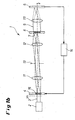
- Fig. 1a is a schematic view showing a first exemplary embodiment of a holographic storage system 1 according to the invention.
- the system 1 comprises a light source 2 providing a reference beam 3.
- the light source 2 generally consists of a laser and a beam expander.
- the light source 2 is followed by a spatial light modulator (SLM) 4 encoding the reference beam 3.
- SLM spatial light modulator
- the system 1 further comprises a detector 5 and means (not shown) arranged along an optical path of the reference beam for holding a holographic storage medium 6 carrying a hologram 7 to be read.
- the storage medium holding means can be any conventional medium-receiving component, such as a CD or DVD tray, a holographic identification card slot, or any other means suitable for keeping the storage medium 6 at a well-defined location within the holographic storage system 1.
- the detector 5 can be a CCD camera, a CMOS, a photodiode matrix or any other known detector type comprising sensor elements arranged in a pixel array.
- the hologram 7 is preferably a Fourier-hologram, due to its smaller sensitivity to surface defects of the storage medium than that of image plane holograms.
- the phase code pattern displayed by the SLM 4, used for phase-coding the reference beam 3 is imaged onto the Fourier-transform of an object beam when creating the hologram 7. Because of its good diffraction efficiency and low wavelength selectivity, e.g. a thin polarisation hologram can be used.
- Suitable holographic storage media are e.g. azo-benzene type photoanizotropic polymers.
- Fig. 1a The embodiment shown in Fig. 1a is designed for reading the holographic storage medium 6 in reflection mode: the reference beam 3 is reflected from a mirror 8 behind the medium 6 and the reconstructed object beam 9 is imaged onto the imaging plane of the detector 5 for capturing an image of the reconstructed hologram 7.
- the reflected beam 9 and the reference beam 3 are separated from each other by a beam splitter 10, which can be a neutral beam splitter or a polarisation beam splitter in case of polarisation holograms, or any other beam separation element such as a beam splitter cube with a central layer discontinuity, as disclosed in EP 1 492 095 A2 .
- the SLM 4 is imaged into the plane of the hologram 7 by an imaging system.
- This imaging system comprises preferably a first and second Fourier lenses 11 and 12, arranged before and after the beam splitter 10 as known in the art.
- an aperture 13 can be interposed between the first Fourier lens 11 and the beam splitter 10 improving the imaging quality by limiting the diameter of the beam and providing the further advantage of restricting the definition of the SLM 4 as will be explained later on.
- the reference beam encoding is preferably phase coding to avoid information loss present at amplitude encoding, although amplitude encoding can be applied too, or any other known light modulation encoding (e.g. polarisation encoding, wavelength encoding).
- the phase code can be for example a security key for reading an encrypted hologram 7 or a key for reading a multiplexed hologram 7.
- the invention also relates to applications other than encryption or multiplexing.
- the SLM 4 can also be used as an aperture creating an easy to position circular reference beam 3. This is useful to reduce inter-hologram cross-talk at hologram reconstruction when multiple holograms 7 are written close to each other into the storage medium 6.
- the reference beam 3 When reading the hologram 7 of the storage medium 6, the reference beam 3 needs to be positioned with respect to the storage medium 6.
- the positioning of the reference beam 3 is carried out by displaying a reference beam code pattern encoding the reference beam 3 at different positions on the SLM 4.
- a servo control unit 14 which is connected to the detector 5 for analysing the image detected by the detector 5 and computing a servo signal as will be explained later on.
- the servo signal is used for controlling the position of the code pattern displayed by the SLM 4.
- the servo control unit 14 can be for example a computer, microcontroller or any application-specific electric circuit with the necessary software to operate the SLM 4.
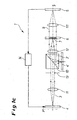
- Fig. 1b illustrates another preferred embodiment of the holographic storage system 1, where the holographic storage medium 6 is read in transmission mode, i.e. the reconstructed object beam 9 is transmitted through the storage medium 6. Accordingly, the detector 5 is arranged on the opposite side of the storage medium 6 and a third Fourier lens 111 can be interposed between the detector 5 and the storage medium 6 for imaging the reconstructed obj ect beam 9 onto the imaging plane of the detector 5.
- Fig. 1c illustrates another preferred embodiment of the holographic storage system 1, which is adapted both for reading and writing holographic storage media 6.
- the storage medium 6 is read in transmission mode.
- the beam splitter 10 is used to unite the reference beam 3 and an object beam 3' coming from an object beam SLM 4' when the system 1 is used for recording a hologram 7 on a storage medium 6.
- the object beam 3' can be provided with a separate light source (not shown), or the light source 2 of the reference beam 3 can be used to provide both beams 3 and 3' as known in the art.
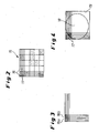
- Fig. 2 illustrates a reference beam phase code pattern 15 displayed on the SLM 4.
- each reference beam code pixel 16 consists of 5 x 5 SLM pixels 17.
- the number of SLM pixels 17 used for displaying a single code pixel 16 can vary depending on the application.
- code pixels 16 consisting of more than one SLM pixel 17 allows for a simple way of shifting the code pattern 15. For example to shift the code pattern 15 by one SLM pixel 17 to the right each code pixel 16a is shifted by one row of SLM pixels 17 as demonstrated in Fig. 3 .
- the new code pixel 16b is displayed by a new block of 5 x 5 SLM pixels 17 consisting of 5 x 4 SLM pixels 17 overlapping with the original code pixel 16a and 1x4 SLM pixels 17 to the right from the original code pixel 16a.
- the code pattern 15 can be shifted in any direction following the above concept, including directions not parallel with the rows or columns of the SLM pixels 17.
- a hologram 7 recorded with a particular reference beam phase code pattern 15 can only be reconstructed with a reference beam encoded with a phase code pattern 15 identical or highly similar to the one used for recording the hologram 7, thus encoding the reference beam 3 allows for security encryption or multiplexing.
- the reference beam code pattern 15 can for example have a size of 10 x 10 code pixels 16 leading to 2100 possible code combinations.
- the hologram 7 should not be readable with reference beam code patterns 15 other than the one used for recording the hologram 7. Therefore only a set of sufficiently distinct code patterns 15 can be used out of the total possible code patterns 15, which in practice is still a very high number, e.g. about 225 code combinations could be used.
- a method of generating distinct code patterns 15 is disclosed in WO 02/05270 .
- the aperture 13 has the additional benefit of restricting the definition of the SLM 4, so that the individual SLM pixels 17 are not distinguishable on the image detected by the detector 5 while the encoding effect of the code pixels 16 is still perceptible.
- the aperture 13 is arranged in the Fourier plane of the SLM 4 (or its close vicinity) in order to filter the high frequency components in the Fourier space thereby blurring the resulting image.
- the code pattern 15 can be created by modulating any other light property or a combination thereof (including phase, amplitude, wavelength and polarisation) as known in the art.
- the reference beam code pattern 15 can be a simple light transmitting inner circle 18 with a non-transparent outer border zone 19 as illustrated in Fig. 4 . This can be achieved for example by using the SLM 4 in amplitude modulation mode and decreasing the amplitude of the border zone 19 while conserving the amplitude of the light within the transmitting circle 18 thus creating the easy to position circular reference beam 3.
- the circular reference beam 3 can be easily positioned by changing the amplitude modulation of the individual SLM pixels 17 so as to create the light transmitting inner circle 18 at another location of the SLM 4.
- a known method to realise amplitude modulation mode is to provide a polariser before and an analyser after the SLM 4.
- the polarisation of the reference beam 3 falling within the inner circle 18 can be left unchanged by the SLM 4, while it can be rotated by 90 degrees within the outer border zone 19. Only the unchanged polarisation will pass through the analyser thus creating the easy to position circular reference beam 3.
- the easy to position circular reference beam 3 can be provided together with phase coding as well, either using the same or a further reference beam encoding SLM 4 disposed along the optical path of the reference beam 3.
- the same SLM can be used for simultaneous phase and amplitude modulation e.g. in ternary modulation mode of special SLMs. Using two SLMs for separate phase and amplitude modulation requires additional optical elements to image the two SLMs onto each other.
- SLM pixel 17 as one code pixel 16 is also at hand for a phase-coded reference beam 3, however it is advantageous to be able to shift the phase pattern in finer steps than the size of a code pixel 16 for the purpose of calculating a misalignment between the reference beam 3 and the storage medium 6.
- the code pattern 15 can be created in any other known way as well as long as it is possible to shift the code pattern 5 on the SLM 4.
- a figure of merit associated with the detected image can be determined.
- the figure of merit is generally a scalar quantity indicative of the pixel misalignment, e.g. average pixel intensity or signal to noise ratio.
- An example for using figures of merit can be found in US 7,116,626 B1 (referred to as a channel metric).
- the reference beam 3 can be repositioned by shifting the code pattern 15 on the SLM.
- the figure of merit is only suitable for indicating the magnitude or degree of misalignment but not the direction of the misalignment. Consequently, if a figure of merit is used for describing the misalignment the figure of merit may need to be recalculated at a number of different reference beam positions.
Landscapes
- Physics & Mathematics (AREA)
- Chemical & Material Sciences (AREA)
- Crystallography & Structural Chemistry (AREA)
- Optics & Photonics (AREA)
- General Physics & Mathematics (AREA)
- Holo Graphy (AREA)
- Optical Recording Or Reproduction (AREA)
Claims (15)
- Système de stockage holographique (1) permettant de lire un hologramme (7) stocké sur un moyen de stockage holographique (6), ledit système (1) comprenant:un moyen de maintien de moyen de stockage disposé le long d'un chemin optique d'un faisceau de référence (3);un modulateur spatial de lumière (SLM) (4) disposé le long dudit chemin optique pour encoder un faisceau de référence (3) avec un motif de code (15);un détecteur (5) pour détecter une image de l'hologramme reconstruit (7); etune unité d'asservissement (14) pour déterminer un désalignement dudit faisceau de référence (3) et dudit moyen de stockage (6) depuis l'image détectée, et pour agir sur ledit SLM (4) pour décaler ledit motif de code (15),dans lequel ledit faisceau de référence (3) est transmis à travers ledit SLM (4).
- Système selon la revendication 1, dans lequel le SLM (4) est un modulateur de lumière de type réseau de pixels, préférablement un micro-dispositif d'affichage, un écran à cristaux liquides ou un écran à cristaux liquides sur silicium.
- Système selon la revendication 1 ou la revendication 2, dans lequel le motif de code (15) comprend une zone interne circulaire (18) entourée d'une zone de bordure (19), les deux zones (18, 19) modulant au moins une propriété de la lumière du faisceau de référence (3) de différentes manières.
- Système selon la revendication 3, dans lequel la zone interne circulaire (18) transmet la lumière et la zone de bordure (19) est non transparente.
- Système selon la revendication 3, dans lequel la polarisation de la lumière effectuée par la zone interne circulaire (18) et la polarisation de la lumière effectuée par la zone de bordure (19) font un certain angle entre elles; et un polariseur est disposé avant le SLM (4) et un analyseur est disposé après le SLM (4), le long dudit chemin optique du faisceau de référence (3).
- Système selon la revendication 2, dans lequel le motif de code (15) est constitué d'une pluralité de pixels de code (16), les pixels de code (16) étant constitués de n x m pixels (17) du SLM (4).
- Système selon la revendication 6, dans lequel le décalage dudit motif de code (15) est effectué en affichant lesdits pixels de code (16) par n x m pixels (17) différents du SLM (4).
- Système selon la revendication 6 ou la revendication 7, dans lequel le motif de code (15) est un motif de code de phase.
- Système selon l'une quelconque des revendications 1 à 8, dans lequel ledit hologramme (7) est un hologramme de transformée de Fourier.
- Système selon la revendication 9, dans lequel une première et une seconde lentilles de transformée de Fourier (11, 12) sont disposées entre ledit SLM (4) et ledit moyen de stockage (6) le long dudit chemin optique.
- Système selon l'une quelconque des revendications 1 à 10, comprenant un SLM de modulation de faisceau d'objet (4') pour créer un faisceau d'objet codé de données (3') et un moyen (10) pour unifier le faisceau de référence encodé (3) et le faisceau d'objet encodé (3') pour écrire un hologramme (7).
- Système selon la revendication 1, dans lequel ledit motif de code de référence (15) est un motif de phase-amplitude, de longueur d'onde et/ou de modulation-polarisation créé par le SLM (4).
- Procédé de lecture d'un hologramme stocké sur un moyen de stockage holographique comprenant les étapes suivantes:a) coder un faisceau de référence avec un motif de code créé par un modulateur spatial de lumière (SLM), où ledit faisceau de référence est transmis à travers ledit SLM;b) détecter une image de l'hologramme reconstruit;c) déterminer un désalignement dudit faisceau de référence et dudit moyen de stockage à partir de l'image détectée; etd) décaler ledit motif de code sur le SLM sur la base, en partie, dudit désalignement.
- Procédé selon la revendication 13, dans lequel le SLM est un modulateur de lumière de type réseau de pixels, préférablement un micro-dispositif d'affichage, un écran à cristaux liquides ou un écran à cristaux liquides sur silicium, et où décaler ledit motif de code est effectué en utilisant des pixels de SLM différents pour créer le motif de code.
- Procédé selon la revendication 14, dans lequel le motif de code est constitué d'une pluralité de pixels de code, les pixels de code étant constitués de n x m pixels du SLM.
Applications Claiming Priority (2)
| Application Number | Priority Date | Filing Date | Title |
|---|---|---|---|
| HU0700133A HU0700133D0 (en) | 2007-02-06 | 2007-02-06 | Holographic storage system for reading a hologram stored on a holographic storage medium and a method carried out the rewith |
| PCT/EP2008/000516 WO2008095607A1 (fr) | 2007-02-06 | 2008-01-24 | Système de stockage holographique permettant de lire un hologramme stocké sur un moyen de stockage holographique et méthode associée |
Publications (2)
| Publication Number | Publication Date |
|---|---|
| EP2126907A1 EP2126907A1 (fr) | 2009-12-02 |
| EP2126907B1 true EP2126907B1 (fr) | 2012-11-14 |
Family
ID=89987324
Family Applications (1)
| Application Number | Title | Priority Date | Filing Date |
|---|---|---|---|
| EP08707228A Not-in-force EP2126907B1 (fr) | 2007-02-06 | 2008-01-24 | Système de stockage holographique permettant de lire un hologramme stocké sur un moyen de stockage holographique et méthode associée |
Country Status (15)
| Country | Link |
|---|---|
| US (1) | US8120827B2 (fr) |
| EP (1) | EP2126907B1 (fr) |
| JP (1) | JP2010518420A (fr) |
| KR (1) | KR20090109099A (fr) |
| CN (1) | CN101606199B (fr) |
| AU (1) | AU2008213456A1 (fr) |
| BR (1) | BRPI0808182A2 (fr) |
| CA (1) | CA2677271A1 (fr) |
| DK (1) | DK2126907T3 (fr) |
| ES (1) | ES2397483T3 (fr) |
| HU (1) | HU0700133D0 (fr) |
| MX (1) | MX2009007306A (fr) |
| RU (1) | RU2009131893A (fr) |
| TW (1) | TW200842849A (fr) |
| WO (1) | WO2008095607A1 (fr) |
Families Citing this family (5)
| Publication number | Priority date | Publication date | Assignee | Title |
|---|---|---|---|---|
| IE20080795A1 (en) * | 2007-10-03 | 2009-07-08 | Univ Limerick | A multipoint laser doppler vibrometer |
| WO2015166549A1 (fr) * | 2014-04-30 | 2015-11-05 | 株式会社クリュートメディカルシステムズ | Dispositif de mesure de la fonction oculaire |
| KR101575072B1 (ko) | 2014-10-21 | 2015-12-07 | 숭실대학교산학협력단 | 2차원 데이터 구조에서 심볼 간 간섭을 보상하는 방법 및 장치, 이를 수행하기 위한 기록매체 |
| CN109507346A (zh) * | 2018-12-29 | 2019-03-22 | 辽宁通正检测有限公司 | 养殖用水中4种禁用氟喹诺酮药物残留量的检测方法 |
| DE102020210936A1 (de) | 2020-08-31 | 2022-03-03 | Scribos Gmbh | Auslesevorrichtung zum Auslesen holographisch abgelegter Informationen, Verfahren zum Auslesen holographisch abgelegter Informationen, und Auslesesystem zum Auslesen von holographisch abgelegten Informationen. |
Citations (1)
| Publication number | Priority date | Publication date | Assignee | Title |
|---|---|---|---|---|
| EP1881493A1 (fr) * | 2006-07-19 | 2008-01-23 | FUJIFILM Corporation | Dispositif d'enregistrement et/ ou de reproduction d'informations et procédé de reproduction d'informations |
Family Cites Families (15)
| Publication number | Priority date | Publication date | Assignee | Title |
|---|---|---|---|---|
| US5838650A (en) * | 1996-06-26 | 1998-11-17 | Lucent Technologies Inc. | Image quality compensation method and apparatus for holographic data storage system |
| US7095540B1 (en) * | 1999-01-29 | 2006-08-22 | The University Of Connecticut | Optical security system using fourier plane encoding |
| HUP0000518D0 (en) * | 2000-02-04 | 2000-04-28 | Method of placing data signals onto a carrier; method and apparatus for the holographic recording and read-out of data | |
| HU0002596D0 (en) | 2000-07-07 | 2000-08-28 | Method for generating a phase code for holographic data storage | |
| US6958967B2 (en) * | 2000-11-17 | 2005-10-25 | Matsushita Electric Industrial Co., Ltd. | Holographic optical information recording/reproducing device |
| US7116626B1 (en) | 2001-11-27 | 2006-10-03 | Inphase Technologies, Inc. | Micro-positioning movement of holographic data storage system components |
| JP4156911B2 (ja) * | 2002-12-02 | 2008-09-24 | 新オプトウエア株式会社 | 光情報記録媒体、光情報記録装置および光情報再生装置 |
| US7064875B2 (en) * | 2003-03-24 | 2006-06-20 | Fuji Xerox Co., Ltd. | Optical recording apparatus and optical recording/reproducing apparatus |
| JP2006527395A (ja) * | 2003-06-07 | 2006-11-30 | アプリリス,インコーポレイテッド | 高面密度ホログラフィックデータ記憶システム |
| US7773486B2 (en) * | 2003-10-24 | 2010-08-10 | Panasonic Corporation | Two-dimensional photoreceptor array, holographic optical information playback device, and holographic optical information recording device |
| US7088482B2 (en) * | 2004-02-10 | 2006-08-08 | Imation Corp. | Holographic recording techniques using first and second portions of a spatial light modulator |
| US7848595B2 (en) * | 2004-06-28 | 2010-12-07 | Inphase Technologies, Inc. | Processing data pixels in a holographic data storage system |
| JP4590635B2 (ja) * | 2005-04-28 | 2010-12-01 | 新オプトウエア株式会社 | 光情報再生方法、光情報再生装置、光情報記録再生方法及び光情報記録再生装置 |
| EP1880252B1 (fr) * | 2005-05-13 | 2008-10-08 | SeeReal Technologies GmbH | Dispositif de projection et procede de reconstruction holographique de scenes |
| JP4844759B2 (ja) * | 2005-05-18 | 2011-12-28 | 新オプトウエア株式会社 | 記録媒体、光情報記録方法、光情報記録装置、光情報再生方法、光情報再生装置及び記録媒体の製造方法 |
-
2007
- 2007-02-06 HU HU0700133A patent/HU0700133D0/hu unknown
-
2008
- 2008-01-24 MX MX2009007306A patent/MX2009007306A/es not_active Application Discontinuation
- 2008-01-24 AU AU2008213456A patent/AU2008213456A1/en not_active Abandoned
- 2008-01-24 US US12/526,033 patent/US8120827B2/en not_active Expired - Fee Related
- 2008-01-24 CA CA002677271A patent/CA2677271A1/fr not_active Abandoned
- 2008-01-24 DK DK08707228.6T patent/DK2126907T3/da active
- 2008-01-24 EP EP08707228A patent/EP2126907B1/fr not_active Not-in-force
- 2008-01-24 WO PCT/EP2008/000516 patent/WO2008095607A1/fr active Application Filing
- 2008-01-24 KR KR1020097016397A patent/KR20090109099A/ko not_active Application Discontinuation
- 2008-01-24 RU RU2009131893/28A patent/RU2009131893A/ru unknown
- 2008-01-24 JP JP2009547581A patent/JP2010518420A/ja active Pending
- 2008-01-24 BR BRPI0808182-4A patent/BRPI0808182A2/pt not_active IP Right Cessation
- 2008-01-24 CN CN2008800040321A patent/CN101606199B/zh not_active Expired - Fee Related
- 2008-01-24 ES ES08707228T patent/ES2397483T3/es active Active
- 2008-02-05 TW TW097104411A patent/TW200842849A/zh unknown
Patent Citations (1)
| Publication number | Priority date | Publication date | Assignee | Title |
|---|---|---|---|---|
| EP1881493A1 (fr) * | 2006-07-19 | 2008-01-23 | FUJIFILM Corporation | Dispositif d'enregistrement et/ ou de reproduction d'informations et procédé de reproduction d'informations |
Also Published As
| Publication number | Publication date |
|---|---|
| KR20090109099A (ko) | 2009-10-19 |
| US8120827B2 (en) | 2012-02-21 |
| EP2126907A1 (fr) | 2009-12-02 |
| AU2008213456A1 (en) | 2008-08-14 |
| HU0700133D0 (en) | 2007-05-02 |
| ES2397483T3 (es) | 2013-03-07 |
| US20100103487A1 (en) | 2010-04-29 |
| MX2009007306A (es) | 2009-08-13 |
| WO2008095607A1 (fr) | 2008-08-14 |
| BRPI0808182A2 (pt) | 2014-08-05 |
| DK2126907T3 (da) | 2013-02-04 |
| RU2009131893A (ru) | 2011-03-20 |
| CN101606199B (zh) | 2012-03-07 |
| CN101606199A (zh) | 2009-12-16 |
| JP2010518420A (ja) | 2010-05-27 |
| TW200842849A (en) | 2008-11-01 |
| CA2677271A1 (fr) | 2008-08-14 |
Similar Documents
| Publication | Publication Date | Title |
|---|---|---|
| JP5466833B2 (ja) | ページに基づくホログラフィー記録および読み出しを実行する方法 | |
| US7502151B2 (en) | Holographic recording and reconstructing apparatus and method | |
| EP1460622B1 (fr) | Méthode d'enregistrement et de reproduction de données holographiques et support d'enregistrement holographique | |
| EP2136366A2 (fr) | Appareil d'enregistrement d'informations optiques, procédé d'enregistrement d'informations optiques, appareil de reproduction/enregistrement d'informations optiques et procédé de reproduction/enregistrement d'informations optiques | |
| JP2005293630A (ja) | ホログラム記録装置、ホログラム再生装置、ホログラム記録方法、ホログラム再生方法、およびホログラム記録媒体 | |
| EP1708182A2 (fr) | Enregistreur d'hologrammes | |
| EP2126907B1 (fr) | Système de stockage holographique permettant de lire un hologramme stocké sur un moyen de stockage holographique et méthode associée | |
| JP2018137030A (ja) | ホログラム記録再生方法およびホログラム記録再生装置 | |
| JP4748043B2 (ja) | 光記録装置、光記録方法、記録媒体及び再生方法 | |
| WO2007111139A1 (fr) | Méthode d'enregistrement/reproduction, support d'enregistrement et dispositif d'enregistrement/reproduction | |
| EP2118895B1 (fr) | Méthode de lecture d'un hologramme de fourier enregistré sur un milieu de stockage holographique et système de stockage holographique | |
| JP4631473B2 (ja) | ホログラム記録再生装置およびホログラム記録再生方法 | |
| JP2016219086A (ja) | ホログラム記録再生方法およびホログラム記録再生装置 | |
| JP4669927B2 (ja) | 光情報記録方法および光情報再生方法 | |
| US8000207B2 (en) | Method for reproducing hologram | |
| EP1531461A1 (fr) | Systeme d'hologramme | |
| KR20080064357A (ko) | 홀로그래픽 정보 기록/재생 장치의 각도 다중화 방법 | |
| JP2005257885A (ja) | 記録再生装置 | |
| JP2007242145A (ja) | 情報記録装置および情報再生装置 |
Legal Events
| Date | Code | Title | Description |
|---|---|---|---|
| PUAI | Public reference made under article 153(3) epc to a published international application that has entered the european phase |
Free format text: ORIGINAL CODE: 0009012 |
|
| 17P | Request for examination filed |
Effective date: 20090907 |
|
| AK | Designated contracting states |
Kind code of ref document: A1 Designated state(s): AT BE BG CH CY CZ DE DK EE ES FI FR GB GR HR HU IE IS IT LI LT LU LV MC MT NL NO PL PT RO SE SI SK TR |
|
| 17Q | First examination report despatched |
Effective date: 20100105 |
|
| DAX | Request for extension of the european patent (deleted) | ||
| GRAP | Despatch of communication of intention to grant a patent |
Free format text: ORIGINAL CODE: EPIDOSNIGR1 |
|
| RIC1 | Information provided on ipc code assigned before grant |
Ipc: G11B 7/08 20060101ALI20120615BHEP Ipc: G11B 7/1369 20120101ALI20120615BHEP Ipc: G11B 7/0065 20060101AFI20120615BHEP |
|
| RAP1 | Party data changed (applicant data changed or rights of an application transferred) |
Owner name: BAYER INNOVATION GMBH |
|
| GRAS | Grant fee paid |
Free format text: ORIGINAL CODE: EPIDOSNIGR3 |
|
| GRAA | (expected) grant |
Free format text: ORIGINAL CODE: 0009210 |
|
| AK | Designated contracting states |
Kind code of ref document: B1 Designated state(s): AT BE BG CH CY CZ DE DK EE ES FI FR GB GR HR HU IE IS IT LI LT LU LV MC MT NL NO PL PT RO SE SI SK TR |
|
| REG | Reference to a national code |
Ref country code: GB Ref legal event code: FG4D |
|
| REG | Reference to a national code |
Ref country code: AT Ref legal event code: REF Ref document number: 584348 Country of ref document: AT Kind code of ref document: T Effective date: 20121115 Ref country code: CH Ref legal event code: EP |
|
| REG | Reference to a national code |
Ref country code: IE Ref legal event code: FG4D |
|
| REG | Reference to a national code |
Ref country code: DE Ref legal event code: R096 Ref document number: 602008020092 Country of ref document: DE Effective date: 20130110 |
|
| REG | Reference to a national code |
Ref country code: DK Ref legal event code: T3 |
|
| REG | Reference to a national code |
Ref country code: ES Ref legal event code: FG2A Ref document number: 2397483 Country of ref document: ES Kind code of ref document: T3 Effective date: 20130307 |
|
| REG | Reference to a national code |
Ref country code: NL Ref legal event code: VDEP Effective date: 20121114 |
|
| REG | Reference to a national code |
Ref country code: LT Ref legal event code: MG4D |
|
| PG25 | Lapsed in a contracting state [announced via postgrant information from national office to epo] |
Ref country code: LT Free format text: LAPSE BECAUSE OF FAILURE TO SUBMIT A TRANSLATION OF THE DESCRIPTION OR TO PAY THE FEE WITHIN THE PRESCRIBED TIME-LIMIT Effective date: 20121114 Ref country code: SE Free format text: LAPSE BECAUSE OF FAILURE TO SUBMIT A TRANSLATION OF THE DESCRIPTION OR TO PAY THE FEE WITHIN THE PRESCRIBED TIME-LIMIT Effective date: 20121114 Ref country code: HR Free format text: LAPSE BECAUSE OF FAILURE TO SUBMIT A TRANSLATION OF THE DESCRIPTION OR TO PAY THE FEE WITHIN THE PRESCRIBED TIME-LIMIT Effective date: 20121114 Ref country code: FI Free format text: LAPSE BECAUSE OF FAILURE TO SUBMIT A TRANSLATION OF THE DESCRIPTION OR TO PAY THE FEE WITHIN THE PRESCRIBED TIME-LIMIT Effective date: 20121114 Ref country code: NO Free format text: LAPSE BECAUSE OF FAILURE TO SUBMIT A TRANSLATION OF THE DESCRIPTION OR TO PAY THE FEE WITHIN THE PRESCRIBED TIME-LIMIT Effective date: 20130214 |
|
| PGFP | Annual fee paid to national office [announced via postgrant information from national office to epo] |
Ref country code: GB Payment date: 20130123 Year of fee payment: 6 Ref country code: ES Payment date: 20130207 Year of fee payment: 6 Ref country code: DK Payment date: 20130110 Year of fee payment: 6 Ref country code: FR Payment date: 20130204 Year of fee payment: 6 |
|
| PG25 | Lapsed in a contracting state [announced via postgrant information from national office to epo] |
Ref country code: CY Free format text: LAPSE BECAUSE OF FAILURE TO SUBMIT A TRANSLATION OF THE DESCRIPTION OR TO PAY THE FEE WITHIN THE PRESCRIBED TIME-LIMIT Effective date: 20121114 Ref country code: BE Free format text: LAPSE BECAUSE OF FAILURE TO SUBMIT A TRANSLATION OF THE DESCRIPTION OR TO PAY THE FEE WITHIN THE PRESCRIBED TIME-LIMIT Effective date: 20121114 Ref country code: GR Free format text: LAPSE BECAUSE OF FAILURE TO SUBMIT A TRANSLATION OF THE DESCRIPTION OR TO PAY THE FEE WITHIN THE PRESCRIBED TIME-LIMIT Effective date: 20130215 Ref country code: PT Free format text: LAPSE BECAUSE OF FAILURE TO SUBMIT A TRANSLATION OF THE DESCRIPTION OR TO PAY THE FEE WITHIN THE PRESCRIBED TIME-LIMIT Effective date: 20130314 Ref country code: LV Free format text: LAPSE BECAUSE OF FAILURE TO SUBMIT A TRANSLATION OF THE DESCRIPTION OR TO PAY THE FEE WITHIN THE PRESCRIBED TIME-LIMIT Effective date: 20121114 Ref country code: SI Free format text: LAPSE BECAUSE OF FAILURE TO SUBMIT A TRANSLATION OF THE DESCRIPTION OR TO PAY THE FEE WITHIN THE PRESCRIBED TIME-LIMIT Effective date: 20121114 Ref country code: PL Free format text: LAPSE BECAUSE OF FAILURE TO SUBMIT A TRANSLATION OF THE DESCRIPTION OR TO PAY THE FEE WITHIN THE PRESCRIBED TIME-LIMIT Effective date: 20121114 |
|
| PG25 | Lapsed in a contracting state [announced via postgrant information from national office to epo] |
Ref country code: SK Free format text: LAPSE BECAUSE OF FAILURE TO SUBMIT A TRANSLATION OF THE DESCRIPTION OR TO PAY THE FEE WITHIN THE PRESCRIBED TIME-LIMIT Effective date: 20121114 Ref country code: BG Free format text: LAPSE BECAUSE OF FAILURE TO SUBMIT A TRANSLATION OF THE DESCRIPTION OR TO PAY THE FEE WITHIN THE PRESCRIBED TIME-LIMIT Effective date: 20130214 Ref country code: CZ Free format text: LAPSE BECAUSE OF FAILURE TO SUBMIT A TRANSLATION OF THE DESCRIPTION OR TO PAY THE FEE WITHIN THE PRESCRIBED TIME-LIMIT Effective date: 20121114 Ref country code: EE Free format text: LAPSE BECAUSE OF FAILURE TO SUBMIT A TRANSLATION OF THE DESCRIPTION OR TO PAY THE FEE WITHIN THE PRESCRIBED TIME-LIMIT Effective date: 20121114 |
|
| PG25 | Lapsed in a contracting state [announced via postgrant information from national office to epo] |
Ref country code: NL Free format text: LAPSE BECAUSE OF FAILURE TO SUBMIT A TRANSLATION OF THE DESCRIPTION OR TO PAY THE FEE WITHIN THE PRESCRIBED TIME-LIMIT Effective date: 20121114 Ref country code: MC Free format text: LAPSE BECAUSE OF NON-PAYMENT OF DUE FEES Effective date: 20130131 Ref country code: RO Free format text: LAPSE BECAUSE OF FAILURE TO SUBMIT A TRANSLATION OF THE DESCRIPTION OR TO PAY THE FEE WITHIN THE PRESCRIBED TIME-LIMIT Effective date: 20121114 |
|
| PLBE | No opposition filed within time limit |
Free format text: ORIGINAL CODE: 0009261 |
|
| STAA | Information on the status of an ep patent application or granted ep patent |
Free format text: STATUS: NO OPPOSITION FILED WITHIN TIME LIMIT |
|
| 26N | No opposition filed |
Effective date: 20130815 |
|
| REG | Reference to a national code |
Ref country code: IE Ref legal event code: MM4A |
|
| REG | Reference to a national code |
Ref country code: DE Ref legal event code: R097 Ref document number: 602008020092 Country of ref document: DE Effective date: 20130815 |
|
| PG25 | Lapsed in a contracting state [announced via postgrant information from national office to epo] |
Ref country code: IE Free format text: LAPSE BECAUSE OF NON-PAYMENT OF DUE FEES Effective date: 20130124 |
|
| PGFP | Annual fee paid to national office [announced via postgrant information from national office to epo] |
Ref country code: DE Payment date: 20140122 Year of fee payment: 7 Ref country code: CH Payment date: 20140114 Year of fee payment: 7 |
|
| PGFP | Annual fee paid to national office [announced via postgrant information from national office to epo] |
Ref country code: AT Payment date: 20131224 Year of fee payment: 7 |
|
| PG25 | Lapsed in a contracting state [announced via postgrant information from national office to epo] |
Ref country code: MT Free format text: LAPSE BECAUSE OF FAILURE TO SUBMIT A TRANSLATION OF THE DESCRIPTION OR TO PAY THE FEE WITHIN THE PRESCRIBED TIME-LIMIT Effective date: 20121114 |
|
| REG | Reference to a national code |
Ref country code: DK Ref legal event code: EBP Effective date: 20140131 |
|
| GBPC | Gb: european patent ceased through non-payment of renewal fee |
Effective date: 20140124 |
|
| REG | Reference to a national code |
Ref country code: FR Ref legal event code: ST Effective date: 20140930 |
|
| PG25 | Lapsed in a contracting state [announced via postgrant information from national office to epo] |
Ref country code: FR Free format text: LAPSE BECAUSE OF NON-PAYMENT OF DUE FEES Effective date: 20140131 Ref country code: GB Free format text: LAPSE BECAUSE OF NON-PAYMENT OF DUE FEES Effective date: 20140124 |
|
| PG25 | Lapsed in a contracting state [announced via postgrant information from national office to epo] |
Ref country code: DK Free format text: LAPSE BECAUSE OF NON-PAYMENT OF DUE FEES Effective date: 20140131 |
|
| PG25 | Lapsed in a contracting state [announced via postgrant information from national office to epo] |
Ref country code: TR Free format text: LAPSE BECAUSE OF FAILURE TO SUBMIT A TRANSLATION OF THE DESCRIPTION OR TO PAY THE FEE WITHIN THE PRESCRIBED TIME-LIMIT Effective date: 20121114 |
|
| PG25 | Lapsed in a contracting state [announced via postgrant information from national office to epo] |
Ref country code: HU Free format text: LAPSE BECAUSE OF FAILURE TO SUBMIT A TRANSLATION OF THE DESCRIPTION OR TO PAY THE FEE WITHIN THE PRESCRIBED TIME-LIMIT; INVALID AB INITIO Effective date: 20080124 Ref country code: LU Free format text: LAPSE BECAUSE OF NON-PAYMENT OF DUE FEES Effective date: 20130124 |
|
| REG | Reference to a national code |
Ref country code: DE Ref legal event code: R119 Ref document number: 602008020092 Country of ref document: DE |
|
| REG | Reference to a national code |
Ref country code: CH Ref legal event code: PL |
|
| REG | Reference to a national code |
Ref country code: AT Ref legal event code: MM01 Ref document number: 584348 Country of ref document: AT Kind code of ref document: T Effective date: 20150124 |
|
| PG25 | Lapsed in a contracting state [announced via postgrant information from national office to epo] |
Ref country code: DE Free format text: LAPSE BECAUSE OF NON-PAYMENT OF DUE FEES Effective date: 20150801 Ref country code: CH Free format text: LAPSE BECAUSE OF NON-PAYMENT OF DUE FEES Effective date: 20150131 Ref country code: LI Free format text: LAPSE BECAUSE OF NON-PAYMENT OF DUE FEES Effective date: 20150131 |
|
| PG25 | Lapsed in a contracting state [announced via postgrant information from national office to epo] |
Ref country code: AT Free format text: LAPSE BECAUSE OF NON-PAYMENT OF DUE FEES Effective date: 20150124 |
|
| PG25 | Lapsed in a contracting state [announced via postgrant information from national office to epo] |
Ref country code: IS Free format text: LAPSE BECAUSE OF FAILURE TO SUBMIT A TRANSLATION OF THE DESCRIPTION OR TO PAY THE FEE WITHIN THE PRESCRIBED TIME-LIMIT Effective date: 20121114 Ref country code: IT Free format text: LAPSE BECAUSE OF NON-PAYMENT OF DUE FEES Effective date: 20140124 |
|
| PG25 | Lapsed in a contracting state [announced via postgrant information from national office to epo] |
Ref country code: ES Free format text: LAPSE BECAUSE OF NON-PAYMENT OF DUE FEES Effective date: 20140125 |