EP2126295B1 - Exhaust gas after treatment system and method - Google Patents
Exhaust gas after treatment system and method Download PDFInfo
- Publication number
- EP2126295B1 EP2126295B1 EP08712734.6A EP08712734A EP2126295B1 EP 2126295 B1 EP2126295 B1 EP 2126295B1 EP 08712734 A EP08712734 A EP 08712734A EP 2126295 B1 EP2126295 B1 EP 2126295B1
- Authority
- EP
- European Patent Office
- Prior art keywords
- exhaust gas
- particulate filter
- diesel particulate
- diesel
- catalyst
- Prior art date
- Legal status (The legal status is an assumption and is not a legal conclusion. Google has not performed a legal analysis and makes no representation as to the accuracy of the status listed.)
- Active
Links
Images


Classifications
-
- F—MECHANICAL ENGINEERING; LIGHTING; HEATING; WEAPONS; BLASTING
- F01—MACHINES OR ENGINES IN GENERAL; ENGINE PLANTS IN GENERAL; STEAM ENGINES
- F01N—GAS-FLOW SILENCERS OR EXHAUST APPARATUS FOR MACHINES OR ENGINES IN GENERAL; GAS-FLOW SILENCERS OR EXHAUST APPARATUS FOR INTERNAL COMBUSTION ENGINES
- F01N3/00—Exhaust or silencing apparatus having means for purifying, rendering innocuous, or otherwise treating exhaust
- F01N3/08—Exhaust or silencing apparatus having means for purifying, rendering innocuous, or otherwise treating exhaust for rendering innocuous
- F01N3/10—Exhaust or silencing apparatus having means for purifying, rendering innocuous, or otherwise treating exhaust for rendering innocuous by thermal or catalytic conversion of noxious components of exhaust
- F01N3/18—Exhaust or silencing apparatus having means for purifying, rendering innocuous, or otherwise treating exhaust for rendering innocuous by thermal or catalytic conversion of noxious components of exhaust characterised by methods of operation; Control
- F01N3/20—Exhaust or silencing apparatus having means for purifying, rendering innocuous, or otherwise treating exhaust for rendering innocuous by thermal or catalytic conversion of noxious components of exhaust characterised by methods of operation; Control specially adapted for catalytic conversion ; Methods of operation or control of catalytic converters
- F01N3/2066—Selective catalytic reduction [SCR]
-
- F—MECHANICAL ENGINEERING; LIGHTING; HEATING; WEAPONS; BLASTING
- F01—MACHINES OR ENGINES IN GENERAL; ENGINE PLANTS IN GENERAL; STEAM ENGINES
- F01N—GAS-FLOW SILENCERS OR EXHAUST APPARATUS FOR MACHINES OR ENGINES IN GENERAL; GAS-FLOW SILENCERS OR EXHAUST APPARATUS FOR INTERNAL COMBUSTION ENGINES
- F01N13/00—Exhaust or silencing apparatus characterised by constructional features ; Exhaust or silencing apparatus, or parts thereof, having pertinent characteristics not provided for in, or of interest apart from, groups F01N1/00 - F01N5/00, F01N9/00, F01N11/00
- F01N13/009—Exhaust or silencing apparatus characterised by constructional features ; Exhaust or silencing apparatus, or parts thereof, having pertinent characteristics not provided for in, or of interest apart from, groups F01N1/00 - F01N5/00, F01N9/00, F01N11/00 having two or more separate purifying devices arranged in series
-
- F—MECHANICAL ENGINEERING; LIGHTING; HEATING; WEAPONS; BLASTING
- F01—MACHINES OR ENGINES IN GENERAL; ENGINE PLANTS IN GENERAL; STEAM ENGINES
- F01N—GAS-FLOW SILENCERS OR EXHAUST APPARATUS FOR MACHINES OR ENGINES IN GENERAL; GAS-FLOW SILENCERS OR EXHAUST APPARATUS FOR INTERNAL COMBUSTION ENGINES
- F01N3/00—Exhaust or silencing apparatus having means for purifying, rendering innocuous, or otherwise treating exhaust
- F01N3/02—Exhaust or silencing apparatus having means for purifying, rendering innocuous, or otherwise treating exhaust for cooling, or for removing solid constituents of, exhaust
- F01N3/021—Exhaust or silencing apparatus having means for purifying, rendering innocuous, or otherwise treating exhaust for cooling, or for removing solid constituents of, exhaust by means of filters
- F01N3/023—Exhaust or silencing apparatus having means for purifying, rendering innocuous, or otherwise treating exhaust for cooling, or for removing solid constituents of, exhaust by means of filters using means for regenerating the filters, e.g. by burning trapped particles
- F01N3/0231—Exhaust or silencing apparatus having means for purifying, rendering innocuous, or otherwise treating exhaust for cooling, or for removing solid constituents of, exhaust by means of filters using means for regenerating the filters, e.g. by burning trapped particles using special exhaust apparatus upstream of the filter for producing nitrogen dioxide, e.g. for continuous filter regeneration systems [CRT]
-
- F—MECHANICAL ENGINEERING; LIGHTING; HEATING; WEAPONS; BLASTING
- F01—MACHINES OR ENGINES IN GENERAL; ENGINE PLANTS IN GENERAL; STEAM ENGINES
- F01N—GAS-FLOW SILENCERS OR EXHAUST APPARATUS FOR MACHINES OR ENGINES IN GENERAL; GAS-FLOW SILENCERS OR EXHAUST APPARATUS FOR INTERNAL COMBUSTION ENGINES
- F01N3/00—Exhaust or silencing apparatus having means for purifying, rendering innocuous, or otherwise treating exhaust
- F01N3/02—Exhaust or silencing apparatus having means for purifying, rendering innocuous, or otherwise treating exhaust for cooling, or for removing solid constituents of, exhaust
- F01N3/021—Exhaust or silencing apparatus having means for purifying, rendering innocuous, or otherwise treating exhaust for cooling, or for removing solid constituents of, exhaust by means of filters
- F01N3/033—Exhaust or silencing apparatus having means for purifying, rendering innocuous, or otherwise treating exhaust for cooling, or for removing solid constituents of, exhaust by means of filters in combination with other devices
- F01N3/035—Exhaust or silencing apparatus having means for purifying, rendering innocuous, or otherwise treating exhaust for cooling, or for removing solid constituents of, exhaust by means of filters in combination with other devices with catalytic reactors, e.g. catalysed diesel particulate filters
-
- F—MECHANICAL ENGINEERING; LIGHTING; HEATING; WEAPONS; BLASTING
- F01—MACHINES OR ENGINES IN GENERAL; ENGINE PLANTS IN GENERAL; STEAM ENGINES
- F01N—GAS-FLOW SILENCERS OR EXHAUST APPARATUS FOR MACHINES OR ENGINES IN GENERAL; GAS-FLOW SILENCERS OR EXHAUST APPARATUS FOR INTERNAL COMBUSTION ENGINES
- F01N3/00—Exhaust or silencing apparatus having means for purifying, rendering innocuous, or otherwise treating exhaust
- F01N3/08—Exhaust or silencing apparatus having means for purifying, rendering innocuous, or otherwise treating exhaust for rendering innocuous
- F01N3/10—Exhaust or silencing apparatus having means for purifying, rendering innocuous, or otherwise treating exhaust for rendering innocuous by thermal or catalytic conversion of noxious components of exhaust
- F01N3/103—Oxidation catalysts for HC and CO only
-
- F—MECHANICAL ENGINEERING; LIGHTING; HEATING; WEAPONS; BLASTING
- F01—MACHINES OR ENGINES IN GENERAL; ENGINE PLANTS IN GENERAL; STEAM ENGINES
- F01N—GAS-FLOW SILENCERS OR EXHAUST APPARATUS FOR MACHINES OR ENGINES IN GENERAL; GAS-FLOW SILENCERS OR EXHAUST APPARATUS FOR INTERNAL COMBUSTION ENGINES
- F01N3/00—Exhaust or silencing apparatus having means for purifying, rendering innocuous, or otherwise treating exhaust
- F01N3/08—Exhaust or silencing apparatus having means for purifying, rendering innocuous, or otherwise treating exhaust for rendering innocuous
- F01N3/10—Exhaust or silencing apparatus having means for purifying, rendering innocuous, or otherwise treating exhaust for rendering innocuous by thermal or catalytic conversion of noxious components of exhaust
- F01N3/105—General auxiliary catalysts, e.g. upstream or downstream of the main catalyst
- F01N3/106—Auxiliary oxidation catalysts
-
- F—MECHANICAL ENGINEERING; LIGHTING; HEATING; WEAPONS; BLASTING
- F01—MACHINES OR ENGINES IN GENERAL; ENGINE PLANTS IN GENERAL; STEAM ENGINES
- F01N—GAS-FLOW SILENCERS OR EXHAUST APPARATUS FOR MACHINES OR ENGINES IN GENERAL; GAS-FLOW SILENCERS OR EXHAUST APPARATUS FOR INTERNAL COMBUSTION ENGINES
- F01N3/00—Exhaust or silencing apparatus having means for purifying, rendering innocuous, or otherwise treating exhaust
- F01N3/08—Exhaust or silencing apparatus having means for purifying, rendering innocuous, or otherwise treating exhaust for rendering innocuous
- F01N3/10—Exhaust or silencing apparatus having means for purifying, rendering innocuous, or otherwise treating exhaust for rendering innocuous by thermal or catalytic conversion of noxious components of exhaust
- F01N3/18—Exhaust or silencing apparatus having means for purifying, rendering innocuous, or otherwise treating exhaust for rendering innocuous by thermal or catalytic conversion of noxious components of exhaust characterised by methods of operation; Control
- F01N3/20—Exhaust or silencing apparatus having means for purifying, rendering innocuous, or otherwise treating exhaust for rendering innocuous by thermal or catalytic conversion of noxious components of exhaust characterised by methods of operation; Control specially adapted for catalytic conversion ; Methods of operation or control of catalytic converters
- F01N3/2053—By-passing catalytic reactors, e.g. to prevent overheating
-
- F—MECHANICAL ENGINEERING; LIGHTING; HEATING; WEAPONS; BLASTING
- F01—MACHINES OR ENGINES IN GENERAL; ENGINE PLANTS IN GENERAL; STEAM ENGINES
- F01N—GAS-FLOW SILENCERS OR EXHAUST APPARATUS FOR MACHINES OR ENGINES IN GENERAL; GAS-FLOW SILENCERS OR EXHAUST APPARATUS FOR INTERNAL COMBUSTION ENGINES
- F01N3/00—Exhaust or silencing apparatus having means for purifying, rendering innocuous, or otherwise treating exhaust
- F01N3/08—Exhaust or silencing apparatus having means for purifying, rendering innocuous, or otherwise treating exhaust for rendering innocuous
- F01N3/10—Exhaust or silencing apparatus having means for purifying, rendering innocuous, or otherwise treating exhaust for rendering innocuous by thermal or catalytic conversion of noxious components of exhaust
- F01N3/18—Exhaust or silencing apparatus having means for purifying, rendering innocuous, or otherwise treating exhaust for rendering innocuous by thermal or catalytic conversion of noxious components of exhaust characterised by methods of operation; Control
- F01N3/20—Exhaust or silencing apparatus having means for purifying, rendering innocuous, or otherwise treating exhaust for rendering innocuous by thermal or catalytic conversion of noxious components of exhaust characterised by methods of operation; Control specially adapted for catalytic conversion ; Methods of operation or control of catalytic converters
- F01N3/2066—Selective catalytic reduction [SCR]
- F01N3/208—Control of selective catalytic reduction [SCR], e.g. dosing of reducing agent
-
- F—MECHANICAL ENGINEERING; LIGHTING; HEATING; WEAPONS; BLASTING
- F02—COMBUSTION ENGINES; HOT-GAS OR COMBUSTION-PRODUCT ENGINE PLANTS
- F02D—CONTROLLING COMBUSTION ENGINES
- F02D41/00—Electrical control of supply of combustible mixture or its constituents
- F02D41/02—Circuit arrangements for generating control signals
- F02D41/14—Introducing closed-loop corrections
- F02D41/1438—Introducing closed-loop corrections using means for determining characteristics of the combustion gases; Sensors therefor
- F02D41/1444—Introducing closed-loop corrections using means for determining characteristics of the combustion gases; Sensors therefor characterised by the characteristics of the combustion gases
- F02D41/146—Introducing closed-loop corrections using means for determining characteristics of the combustion gases; Sensors therefor characterised by the characteristics of the combustion gases the characteristics being an NOx content or concentration
- F02D41/1463—Introducing closed-loop corrections using means for determining characteristics of the combustion gases; Sensors therefor characterised by the characteristics of the combustion gases the characteristics being an NOx content or concentration of the exhaust gases downstream of exhaust gas treatment apparatus
- F02D41/1465—Introducing closed-loop corrections using means for determining characteristics of the combustion gases; Sensors therefor characterised by the characteristics of the combustion gases the characteristics being an NOx content or concentration of the exhaust gases downstream of exhaust gas treatment apparatus with determination means using an estimation
-
- F—MECHANICAL ENGINEERING; LIGHTING; HEATING; WEAPONS; BLASTING
- F02—COMBUSTION ENGINES; HOT-GAS OR COMBUSTION-PRODUCT ENGINE PLANTS
- F02D—CONTROLLING COMBUSTION ENGINES
- F02D41/00—Electrical control of supply of combustible mixture or its constituents
- F02D41/02—Circuit arrangements for generating control signals
- F02D41/14—Introducing closed-loop corrections
- F02D41/1438—Introducing closed-loop corrections using means for determining characteristics of the combustion gases; Sensors therefor
- F02D41/1444—Introducing closed-loop corrections using means for determining characteristics of the combustion gases; Sensors therefor characterised by the characteristics of the combustion gases
- F02D41/1466—Introducing closed-loop corrections using means for determining characteristics of the combustion gases; Sensors therefor characterised by the characteristics of the combustion gases the characteristics being a soot concentration or content
- F02D41/1467—Introducing closed-loop corrections using means for determining characteristics of the combustion gases; Sensors therefor characterised by the characteristics of the combustion gases the characteristics being a soot concentration or content with determination means using an estimation
-
- F—MECHANICAL ENGINEERING; LIGHTING; HEATING; WEAPONS; BLASTING
- F01—MACHINES OR ENGINES IN GENERAL; ENGINE PLANTS IN GENERAL; STEAM ENGINES
- F01N—GAS-FLOW SILENCERS OR EXHAUST APPARATUS FOR MACHINES OR ENGINES IN GENERAL; GAS-FLOW SILENCERS OR EXHAUST APPARATUS FOR INTERNAL COMBUSTION ENGINES
- F01N2410/00—By-passing, at least partially, exhaust from inlet to outlet of apparatus, to atmosphere or to other device
-
- F—MECHANICAL ENGINEERING; LIGHTING; HEATING; WEAPONS; BLASTING
- F01—MACHINES OR ENGINES IN GENERAL; ENGINE PLANTS IN GENERAL; STEAM ENGINES
- F01N—GAS-FLOW SILENCERS OR EXHAUST APPARATUS FOR MACHINES OR ENGINES IN GENERAL; GAS-FLOW SILENCERS OR EXHAUST APPARATUS FOR INTERNAL COMBUSTION ENGINES
- F01N2430/00—Influencing exhaust purification, e.g. starting of catalytic reaction, filter regeneration, or the like, by controlling engine operating characteristics
- F01N2430/08—Influencing exhaust purification, e.g. starting of catalytic reaction, filter regeneration, or the like, by controlling engine operating characteristics by modifying ignition or injection timing
-
- F—MECHANICAL ENGINEERING; LIGHTING; HEATING; WEAPONS; BLASTING
- F01—MACHINES OR ENGINES IN GENERAL; ENGINE PLANTS IN GENERAL; STEAM ENGINES
- F01N—GAS-FLOW SILENCERS OR EXHAUST APPARATUS FOR MACHINES OR ENGINES IN GENERAL; GAS-FLOW SILENCERS OR EXHAUST APPARATUS FOR INTERNAL COMBUSTION ENGINES
- F01N2430/00—Influencing exhaust purification, e.g. starting of catalytic reaction, filter regeneration, or the like, by controlling engine operating characteristics
- F01N2430/10—Influencing exhaust purification, e.g. starting of catalytic reaction, filter regeneration, or the like, by controlling engine operating characteristics by modifying inlet or exhaust valve timing
-
- F—MECHANICAL ENGINEERING; LIGHTING; HEATING; WEAPONS; BLASTING
- F01—MACHINES OR ENGINES IN GENERAL; ENGINE PLANTS IN GENERAL; STEAM ENGINES
- F01N—GAS-FLOW SILENCERS OR EXHAUST APPARATUS FOR MACHINES OR ENGINES IN GENERAL; GAS-FLOW SILENCERS OR EXHAUST APPARATUS FOR INTERNAL COMBUSTION ENGINES
- F01N2510/00—Surface coverings
- F01N2510/06—Surface coverings for exhaust purification, e.g. catalytic reaction
- F01N2510/068—Surface coverings for exhaust purification, e.g. catalytic reaction characterised by the distribution of the catalytic coatings
- F01N2510/0682—Surface coverings for exhaust purification, e.g. catalytic reaction characterised by the distribution of the catalytic coatings having a discontinuous, uneven or partially overlapping coating of catalytic material, e.g. higher amount of material upstream than downstream or vice versa
-
- F—MECHANICAL ENGINEERING; LIGHTING; HEATING; WEAPONS; BLASTING
- F01—MACHINES OR ENGINES IN GENERAL; ENGINE PLANTS IN GENERAL; STEAM ENGINES
- F01N—GAS-FLOW SILENCERS OR EXHAUST APPARATUS FOR MACHINES OR ENGINES IN GENERAL; GAS-FLOW SILENCERS OR EXHAUST APPARATUS FOR INTERNAL COMBUSTION ENGINES
- F01N2560/00—Exhaust systems with means for detecting or measuring exhaust gas components or characteristics
- F01N2560/02—Exhaust systems with means for detecting or measuring exhaust gas components or characteristics the means being an exhaust gas sensor
- F01N2560/026—Exhaust systems with means for detecting or measuring exhaust gas components or characteristics the means being an exhaust gas sensor for measuring or detecting NOx
-
- F—MECHANICAL ENGINEERING; LIGHTING; HEATING; WEAPONS; BLASTING
- F01—MACHINES OR ENGINES IN GENERAL; ENGINE PLANTS IN GENERAL; STEAM ENGINES
- F01N—GAS-FLOW SILENCERS OR EXHAUST APPARATUS FOR MACHINES OR ENGINES IN GENERAL; GAS-FLOW SILENCERS OR EXHAUST APPARATUS FOR INTERNAL COMBUSTION ENGINES
- F01N2560/00—Exhaust systems with means for detecting or measuring exhaust gas components or characteristics
- F01N2560/06—Exhaust systems with means for detecting or measuring exhaust gas components or characteristics the means being a temperature sensor
-
- F—MECHANICAL ENGINEERING; LIGHTING; HEATING; WEAPONS; BLASTING
- F01—MACHINES OR ENGINES IN GENERAL; ENGINE PLANTS IN GENERAL; STEAM ENGINES
- F01N—GAS-FLOW SILENCERS OR EXHAUST APPARATUS FOR MACHINES OR ENGINES IN GENERAL; GAS-FLOW SILENCERS OR EXHAUST APPARATUS FOR INTERNAL COMBUSTION ENGINES
- F01N2560/00—Exhaust systems with means for detecting or measuring exhaust gas components or characteristics
- F01N2560/14—Exhaust systems with means for detecting or measuring exhaust gas components or characteristics having more than one sensor of one kind
-
- F—MECHANICAL ENGINEERING; LIGHTING; HEATING; WEAPONS; BLASTING
- F01—MACHINES OR ENGINES IN GENERAL; ENGINE PLANTS IN GENERAL; STEAM ENGINES
- F01N—GAS-FLOW SILENCERS OR EXHAUST APPARATUS FOR MACHINES OR ENGINES IN GENERAL; GAS-FLOW SILENCERS OR EXHAUST APPARATUS FOR INTERNAL COMBUSTION ENGINES
- F01N2570/00—Exhaust treating apparatus eliminating, absorbing or adsorbing specific elements or compounds
- F01N2570/14—Nitrogen oxides
-
- F—MECHANICAL ENGINEERING; LIGHTING; HEATING; WEAPONS; BLASTING
- F01—MACHINES OR ENGINES IN GENERAL; ENGINE PLANTS IN GENERAL; STEAM ENGINES
- F01N—GAS-FLOW SILENCERS OR EXHAUST APPARATUS FOR MACHINES OR ENGINES IN GENERAL; GAS-FLOW SILENCERS OR EXHAUST APPARATUS FOR INTERNAL COMBUSTION ENGINES
- F01N2610/00—Adding substances to exhaust gases
- F01N2610/02—Adding substances to exhaust gases the substance being ammonia or urea
-
- F—MECHANICAL ENGINEERING; LIGHTING; HEATING; WEAPONS; BLASTING
- F01—MACHINES OR ENGINES IN GENERAL; ENGINE PLANTS IN GENERAL; STEAM ENGINES
- F01N—GAS-FLOW SILENCERS OR EXHAUST APPARATUS FOR MACHINES OR ENGINES IN GENERAL; GAS-FLOW SILENCERS OR EXHAUST APPARATUS FOR INTERNAL COMBUSTION ENGINES
- F01N2610/00—Adding substances to exhaust gases
- F01N2610/03—Adding substances to exhaust gases the substance being hydrocarbons, e.g. engine fuel
-
- F—MECHANICAL ENGINEERING; LIGHTING; HEATING; WEAPONS; BLASTING
- F01—MACHINES OR ENGINES IN GENERAL; ENGINE PLANTS IN GENERAL; STEAM ENGINES
- F01N—GAS-FLOW SILENCERS OR EXHAUST APPARATUS FOR MACHINES OR ENGINES IN GENERAL; GAS-FLOW SILENCERS OR EXHAUST APPARATUS FOR INTERNAL COMBUSTION ENGINES
- F01N2900/00—Details of electrical control or of the monitoring of the exhaust gas treating apparatus
- F01N2900/06—Parameters used for exhaust control or diagnosing
- F01N2900/14—Parameters used for exhaust control or diagnosing said parameters being related to the exhaust gas
- F01N2900/1402—Exhaust gas composition
-
- F—MECHANICAL ENGINEERING; LIGHTING; HEATING; WEAPONS; BLASTING
- F01—MACHINES OR ENGINES IN GENERAL; ENGINE PLANTS IN GENERAL; STEAM ENGINES
- F01N—GAS-FLOW SILENCERS OR EXHAUST APPARATUS FOR MACHINES OR ENGINES IN GENERAL; GAS-FLOW SILENCERS OR EXHAUST APPARATUS FOR INTERNAL COMBUSTION ENGINES
- F01N3/00—Exhaust or silencing apparatus having means for purifying, rendering innocuous, or otherwise treating exhaust
- F01N3/02—Exhaust or silencing apparatus having means for purifying, rendering innocuous, or otherwise treating exhaust for cooling, or for removing solid constituents of, exhaust
- F01N3/021—Exhaust or silencing apparatus having means for purifying, rendering innocuous, or otherwise treating exhaust for cooling, or for removing solid constituents of, exhaust by means of filters
- F01N3/033—Exhaust or silencing apparatus having means for purifying, rendering innocuous, or otherwise treating exhaust for cooling, or for removing solid constituents of, exhaust by means of filters in combination with other devices
-
- F—MECHANICAL ENGINEERING; LIGHTING; HEATING; WEAPONS; BLASTING
- F01—MACHINES OR ENGINES IN GENERAL; ENGINE PLANTS IN GENERAL; STEAM ENGINES
- F01N—GAS-FLOW SILENCERS OR EXHAUST APPARATUS FOR MACHINES OR ENGINES IN GENERAL; GAS-FLOW SILENCERS OR EXHAUST APPARATUS FOR INTERNAL COMBUSTION ENGINES
- F01N3/00—Exhaust or silencing apparatus having means for purifying, rendering innocuous, or otherwise treating exhaust
- F01N3/08—Exhaust or silencing apparatus having means for purifying, rendering innocuous, or otherwise treating exhaust for rendering innocuous
- F01N3/10—Exhaust or silencing apparatus having means for purifying, rendering innocuous, or otherwise treating exhaust for rendering innocuous by thermal or catalytic conversion of noxious components of exhaust
- F01N3/18—Exhaust or silencing apparatus having means for purifying, rendering innocuous, or otherwise treating exhaust for rendering innocuous by thermal or catalytic conversion of noxious components of exhaust characterised by methods of operation; Control
- F01N3/20—Exhaust or silencing apparatus having means for purifying, rendering innocuous, or otherwise treating exhaust for rendering innocuous by thermal or catalytic conversion of noxious components of exhaust characterised by methods of operation; Control specially adapted for catalytic conversion ; Methods of operation or control of catalytic converters
- F01N3/206—Adding periodically or continuously substances to exhaust gases for promoting purification, e.g. catalytic material in liquid form, NOx reducing agents
-
- F—MECHANICAL ENGINEERING; LIGHTING; HEATING; WEAPONS; BLASTING
- F02—COMBUSTION ENGINES; HOT-GAS OR COMBUSTION-PRODUCT ENGINE PLANTS
- F02D—CONTROLLING COMBUSTION ENGINES
- F02D2200/00—Input parameters for engine control
- F02D2200/02—Input parameters for engine control the parameters being related to the engine
- F02D2200/08—Exhaust gas treatment apparatus parameters
- F02D2200/0812—Particle filter loading
-
- Y—GENERAL TAGGING OF NEW TECHNOLOGICAL DEVELOPMENTS; GENERAL TAGGING OF CROSS-SECTIONAL TECHNOLOGIES SPANNING OVER SEVERAL SECTIONS OF THE IPC; TECHNICAL SUBJECTS COVERED BY FORMER USPC CROSS-REFERENCE ART COLLECTIONS [XRACs] AND DIGESTS
- Y02—TECHNOLOGIES OR APPLICATIONS FOR MITIGATION OR ADAPTATION AGAINST CLIMATE CHANGE
- Y02A—TECHNOLOGIES FOR ADAPTATION TO CLIMATE CHANGE
- Y02A50/00—TECHNOLOGIES FOR ADAPTATION TO CLIMATE CHANGE in human health protection, e.g. against extreme weather
- Y02A50/20—Air quality improvement or preservation, e.g. vehicle emission control or emission reduction by using catalytic converters
-
- Y—GENERAL TAGGING OF NEW TECHNOLOGICAL DEVELOPMENTS; GENERAL TAGGING OF CROSS-SECTIONAL TECHNOLOGIES SPANNING OVER SEVERAL SECTIONS OF THE IPC; TECHNICAL SUBJECTS COVERED BY FORMER USPC CROSS-REFERENCE ART COLLECTIONS [XRACs] AND DIGESTS
- Y02—TECHNOLOGIES OR APPLICATIONS FOR MITIGATION OR ADAPTATION AGAINST CLIMATE CHANGE
- Y02T—CLIMATE CHANGE MITIGATION TECHNOLOGIES RELATED TO TRANSPORTATION
- Y02T10/00—Road transport of goods or passengers
- Y02T10/10—Internal combustion engine [ICE] based vehicles
- Y02T10/12—Improving ICE efficiencies
Landscapes
- Engineering & Computer Science (AREA)
- Chemical & Material Sciences (AREA)
- Combustion & Propulsion (AREA)
- General Engineering & Computer Science (AREA)
- Mechanical Engineering (AREA)
- Chemical Kinetics & Catalysis (AREA)
- Toxicology (AREA)
- Health & Medical Sciences (AREA)
- Materials Engineering (AREA)
- Exhaust Gas After Treatment (AREA)
- Processes For Solid Components From Exhaust (AREA)
- Exhaust Gas Treatment By Means Of Catalyst (AREA)
- Physical Or Chemical Processes And Apparatus (AREA)
- Separation Of Particles Using Liquids (AREA)
- Cylinder Crankcases Of Internal Combustion Engines (AREA)
- Investigating Or Analysing Materials By Optical Means (AREA)
- Chimneys And Flues (AREA)
Abstract
Description
- The present invention relates to a method and apparatus for purifying exhaust gases from a diesel engine, more particularly the present invention relates to a method and apparatus for purifying exhaust gases from a diesel engine which is capable of removing particulates and NOx contained in the exhaust gases.
- Present regulatory conditions in the automotive market have led to an increasing demand to improve fuel economy and reduce emissions in present vehicles. These regulatory conditions must be balanced with the demands of a consumer for high performance and quick response for a vehicle.
- A diesel engine has an efficiency of up to about 52% and is thus the best converter of fossil energy. NOx emission concentration is dependent upon local oxygen atom concentration and the local temperature. Said high efficiency is however only possible at an elevated combustion temperature at which high NOx levels are inevitable. Moreover, a suppression of NOx formation by internal means (air/fuel ratio) has the tendency to cause an increase in particulates, known as the NOx-particulates trade off. Furthermore, an excess of oxygen in the exhaust gas from a diesel engine prevents the use of stoichiometric 3-way-catalyst technology for reduction of NOx as is used in gasoline engine cars from the late 80-ties.
- Reducing the oxides of nitrogen (NOx) and particulate matter (PM) in exhaust gases from a diesel engine has become a very important problem in view of the protection of environment and the saving of finite fossil energy supply.
- For the coming legislation (US10, EU VI etc) it may be necessary to have a combination of a diesel oxygen catalyst (DOC), a diesel particulate filter (DPF) and a selective catalytic reduction (SCR) catalyst in the exhaust system. When designing the DOC and the DPF for a combined system, the noble metal loading is generally a compromise. Good NO-oxidation (i.e. good passive regeneration) and good HC-oxidation (i.e. good O2-regeneration and exhaust after treatment system (EATS) heating) require high noble metal loading. However, a too high noble metal loading (i.e. too high NO-oxidation) will decrease NOx-conversion efficiency in the SCR, and also lead to emissions of the green house gas N2O. When taking into account that the NO- and HC-oxidation must be sufficient also for an aged catalyst, this problem becomes even greater. In the end, if high SCR-activity is needed on the fresh system (for e.g. certification), the aged NO- and HC oxidation will be less than optimal.
-
WO 2004/071646 discloses a system and method of NOx abatement. Downstream of the engine there is provided an oxidation catalyst, a particulate filter, a NOx adsorber and a SCR catalyst. -
WO 01/12320 - Today the catalyst specification is a compromise and the engine parameters are set to fulfil the certification cycle regarding NOx. In
JP 2006207512 a - As explained above, there is a problem associated with prior art methods and - apparatuses for purifying exhaust gases from a diesel engine.
- The object of the invention is to provide an exhaust gas after treatment system and method which at least reduce the above mentioned problems.
- The objects are achieved by the features of the independent claims. The other claims and the description disclose advantageous example embodiments of the invention.
- According to a first aspect of the invention an exhaust gas after treatment system comprising a diesel particulate filter unit (DPFU) arranged downstream of a diesel engine. A NO2 reduction catalyst arranged downstream of said DPFU. A selective catalytic reduction (SCR) arrangement arranged downstream of said NO2 reduction catalyst. A first injector for feeding reducing agent into the exhaust gas arranged downstream said particulate filter and upstream said NO2 reduction catalyst. A second injector for feeding reducing agent into the exhaust gas arranged downstream said NO2 reduction catalyst and upstream said selective catalytic reduction (SCR) arrangement.
- An advantage with the present invention is that it allows high noble metal loading on the DOC and/or the DPF resulting in good NO- and HC-oxidation and at the same time as an optimal NO2/NO ratio may be achieved for the SCR.
- Another advantage with the present invention is that one may achieve high passive regeneration and HC oxidation in the DPF system and maintaining a good NO2/NO ratio for high NOx-conversion in the SCR-system for a fresh as well as an aged system.
- Another advantage with the present invention is that it will be possible to use a smaller SCR-catalyst, giving both cost, space and weight benefits.
- In yet another example embodiment of the present invention said DPF is coated with an oxidation catalyst material. An advantage with this embodiment is that one will still further save space, cost and weight.
- The DPFU may have the DOC upstream of the DPF.
- In still another example embodiment a heat generator is provided between said internal combustion engine and the DPF or DPFU. An advantage with this embodiment is that one may control the temperature in the EATS in an appropriate manner, for instance to suppress or activate one or more of the reactions taking place in the EATS.
- The heat generator may consist of a DOC able to convert fuel to carbon dioxide and water. The heat generator may consist of a burner. A NO2 sensor may be provided downstream and/or downstream the NO2 reduction catalyst. The N02 sensor may be a virtual sensor. The N02 reduction catalyst may be applied as a zone coating on the DPF and said first injector may be arranged upstream said zone coating. The N02 reduction catalyst may be arranged as a zone coating on the SCR arrangement and said first and second injector may be provided as a single unit arranged downstream said DPFU and upstream of said N02 reduction catalyst and SCR arrangement.
- According to another aspect of the present invention An exhaust gas after treatment method comprising the actions of: oxidizing NO into NO2 and trapping combustion particles in a diesel particulate filter unit (DPFU) arranged in direct fluid communication with an internal combustion engine, regulating NO2 content in a NO2 reduction catalyst arranged downstream of said (DPFU), reducing NO2 into NO in a selective catalytic reduction (SCR) arrangement arranged downstream of said NO2 reduction catalyst, injecting a reducing agent by a first injector into the exhaust gas arranged downstream said DPFU and upstream said NO2 reduction catalyst, injecting a reducing agent by a second injector into the exhaust gas arranged downstream said NO2 reduction catalyst and upstream said selective catalytic reduction SCR arrangement.
- According to another aspect of the invention a computer program storable on a computer readable medium, comprising a program code for use in a method comprising at least the steps of
- This computer program can be adapted to be downloaded to a support unit or one of its components when run on a computer which is connected to the internet.
- With reference to the appended drawings below follows a more detailed description of embodiments of the invention cited as examples.
- In the drawings:
-
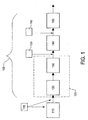
Fig. 1 shows a schematic illustration of a first example embodiment of an exhaust gas after treatment system according to the present invention in fluid connection with an internal combustion engine. -
Fig. 2 shows a schematic illustration of a second example embodiment of an exhaust gas after treatment system according to the present invention in fluid connection with an internal combustion engine. -
Fig. 3 shows a schematic illustration of a third example embodiment of an exhaust gas after treatment system according to the present invention in fluid connection with an internal combustion engine. -
Fig. 4 shows a schematic illustration of a fourth example embodiment of an exhaust gas after treatment system according to the present invention in fluid connection with an internal combustion engine. - In the drawings, equal or similar elements are referred to by equal reference numerals. The drawings are merely schematic representations, not intended to portray specific parameters of the invention. Moreover, the drawings are intended to depict only typical embodiments of the invention and therefore should not be considered as limiting the scope of the invention.
- In
Fig. 1 a first example embodiment of an exhaust gas after treatment system (EATS) 100 according to the present invention is schematically illustrated. Said EATS is fluidly connected to aninternal combustion engine 110, e.g., a diesel engine. Said EATS 100 comprising a diesel particulate filter unit (DPFU) 125, aN02 reduction catalyst 140, a selective catalytic reduction (SCR) 150, a firstreductant injector 135 and asecond reductant injector 145. - The diesel
particulate filter unit 125 is in direct fluid communication with theinternal combustion engine 110. Said dieselparticulate filter unit 115 comprises a diesel oxidation catalyst (DOC) 120 and a diesel particulate filter (DPF) 130. TheDOC 120 is in this embodiment arranged upstream of saidDPF 130. - The reaction taking place in the
DOC 120 may be as follows:
(1) NO + ½O2->NO2
- The temperature in the
DOC 120 is depending inter alia of catalyst material; HC, CO and 02 content and mass flow. The catalytic reaction may start inDOC 120 at about 200°C and may have its maximum catalytic reaction temperature of about 300-400°C. After reaching the maximum reaction temperature the reaction may decline, which declining is depending on the equilibrium reaction, where the reverse reaction
(2) NO2 -> ½O2 + NO
is more temperature dependent than equation (1). - The
DOC 120 is usually built up in the form of a monolithic structure made of cordierite or metal. Said monolithic structure may be coated with a catalytic material in the form of a base metal oxide and a precious metal, which could be Platinum and/or Palladium. - The reaction taking place in the DPF (130) may be as follows:
(3) 2NO2 + C -> NO + CO2
- The temperature in the
DPF 130 may be affected by the thickness of the soot layer in theDPF 130 and may be as low as about 200°C, but becomes effective above 250°C. At higher temperatures than about 700°C, the aging of theDPF 130 as such and the catalyst(s) arranged downstream said DPF130 may be heavily affected. - The
DPF 130 may be built up from porous forms of cordierite or silicon carbide or sintered metal powder. Said porous form may be coated with a catalytic material in the form of a base metal oxide and a precious metal, which could be Platinum and/or Palladium. - If too much soot is trapped in the
DPF 130, which may be caused by a too low temperature and/or to low NOx/soot from the engine, one may use a heat generator upstream saidDPF 130 in order to heat theDPF 130 to an appropriate working temperature. Said heat generator may take different forms. In a first example embodiment the temperature in theDPF 130 may be raised on demand by post-injection of diesel into one or more cylinders of theinternal combustion engine 110 and/or post-injection of diesel into the exhaust system upstream of saidDOC 120, denoted by 115 infigure 1 . The reaction in theDOC 120 may under such circumstances be as depicted by equation (4) instead of the equation as depicted above by (1):
(4) 302 + 2CH2 -> 2CO2 + 2H20
- The temperature of the reaction (4) depends inter alia of the content of HC. It may start at 200°C for reaching DOC outlet temperature of about 350°C and may start at 280°C for reaching a peak temperature of 600°C.
- The catalytic material and/or the temperature in the
DOC 120 affect which one of the equations (1) or (4) is dominating. One may optimize for reaction No. (4), if the purpose ofDOC 120 is to increase the temperature of the exhaust gases and one may optimize for reaction No. (1), if the purpose of theDOC 120 is to produce NO2. - Another example of heat generators may be electric heated catalyst.
- If the Nox/soot is high it is only required to increase of the temperature in the
DOC 120 to about 400°C for removing SOx which prohibits reaction No (1). - Another reaction taking place in the
DPF 130 is as follows:
(5) O2 + C -> CO2
- The temperature of reaction (5) is about 600°C, which may be somewhat decreased if the filter is coated with catalyst or if the fuel is added with catalyst to about 450°C. The lower temperature may necessitate a catalyst material added to the fuel, which in turn is adsorbed by the soot particles.
- Downstream said
DPF 130 saidN02 reduction catalyst 140 is arranged. In saidN02 reduction catalyst 140 the following reactions may take place:
(6) 2NO2 + CH2 -> NO + CO + H20
(7) 3NO2 + CH2 -> NO + CO2 + H20
- From reactions No. (6) and (7) it is clear that the
N02 reduction catalyst 140 reduces N02 into NO. Without theN02 reduction catalyst 140 it is a trade-off between optimal passive regeneration and HC oxidation in theDOC 120/DPF 130 and high NOx-conversion in theSCR system 150. By adding theN02 reduction catalyst 140 downstream of theDPF 130 such trade-off problem may be solved. TheN02 reduction catalyst 130 acts as a balancer to balance the ratio of NO2/NO into theSCR 150. TheN02 reduction catalyst 140 will allow high noble metal loading on the DOC120 and/or DPF 130 (good NO- and HC-oxidation) at the same time as an optimal NO2/NO ratio may be achieved for theSCR 150. A reducing agent such as fuel (HC based fuel such as diesel) or urea may be added, denoted by 135 upstream of saidN02 reduction catalyst 140 for obtaining the N02 ->NO reduction. - The amount of HC injected to the
N02 reduction catalyst 140 can be controlled to produce desired NO2/NO ratio with a signal from a N02 sensor (not shown) placed before and/or after theN02 reduction catalyst 140. The N02 sensor(s) can be replaced by a virtual N02 sensor. - With the
N02 reduction catalyst 140 it may also be possible to have optimal passive regeneration and HC-oxidation for anaged SCR system 150 while still maintaining high NOx-conversion for the fresh systems. It will also be possible to use a smaller SCR-catalyst 150, giving both cost, space and weight benefits. - The temperature in the
N02 reduction catalyst 140 may be from about 250°C to about 600°C, more details can be found inWO 2006/040533 . TheN02 reduction catalyst 140 may be based on a zeolite material, more details can be found inWO 2006/040533 . - The
SCR 150 is in this embodiment arranged downstream saidN02 reduction catalyst 140. The reactions that may take place in theSCR 150 may be as follows:
(8) 4NO + 4NH3 + O2 ->4N2 + 6H20
(9) 2NO + 2N02 + 4NH3 -> 4N2 + 6H20
(10) 6NO2 + 8NH3 -> 7N2 + 12H20
(11) 4NO2 + 4NH3 -> 2N2 + 2N2O + 6H20
- Because reaction No. (9) is the fastest reaction of reactions (8)-(11) and to avoid reaction No. (11), one wants to keep the ratio of NO/NO2 of about 50:50.
- Reaction No (9) may be effective in a temperature range in the
SCR 150 from about 200°C and higher, the reaction starts however at much lower temperatures but the lower the temperature the slower the reaction. The starting temperature for reaction No (8) in theSCR 150 may be about 250°C. Starting points and temperature ranges is somewhat affected by the choice of catalytic material in theSCR 150. - The
SCR 150 may be built up in the form of a monolithic structure made of cordierite or metal. Said structure may either be coated with Vanadium oxide on top of a titanium oxide comprising some amount of wolfram oxide or a coating comprising zeolite. The zeolite may comprise some iron or copper content or some other appropriate anti ion. There are also vanadium oxide catalysts which are extruded to monolithic structures, i.e., the catalyst and structure is made of the same material. - In the embodiment as illustrated in
figure 1 , aninjector 145 is arranged between theN02 reduction catalyst 140 and theSCR 150. Said injector injects a reductant material upstream of saidSCR 150. The reductant material may be urea, ammonia, ammonia absorbed in water, ammonium carbonate, or metal cloride salts which may adsorb ammoniac. -
Figure 2 illustrates another example embodiment of the exhaust gas after treatment system (EATS) 100 according to the present invention. Said embodiment only differs to the preceding embodiment in that theDPFU 125 comprises a DPF coated with aDOC material 122 instead of as infigure 1 where saidDOC 120 andDPF 130 were separate units. The other features uses same reference numbers as Ifigure 1 and needs therefore no further clarification since the functionality and structure may be the same. Another difference to the embodiment as illustrated infigure 1 is that theinjector 115 has been omitted. Clearly, saidinjector 115 could also be omitted from the embodiment as depicted infigure 1 , i.e., theinjector 115 infigure 1 is optional. - The reaction taking place in the
DPFU 125 infigure 2 is similar to the reaction taking place in theDPF 130 andDOC 120 as illustrated infigure 1 , i.e. reactions No. (1) and (3). - In
figure 3 it is illustrated another example embodiment of the exhaust gas after treatment system (EATS) 100 according to the present invention. This embodiment differs to the one depicted infigure 1 in that aseparate heat generator 121 is arranged between theinternal combustion engine 110 and theDOC 120. Here, similar to the embodiment infigure 2 , theinjector 115 has been omitted. Saidseparate heat generator 121 may comprise of a diesel burner, or an adjustable restrictor in the exhaust system upstream of saidDOC 120. -
Figure 4 illustrates yet another example embodiment of the exhaust gas after treatment system (EATS) 100 according to the present invention. This embodiment differs to the embodiment illustrated infigure 1 in that theN02 reduction catalyst 140 and theSCR 150 are arranged as a combined unit. In one embodiment saidN02 reduction catalyst 140 is arranged as a zone coating on a SCR substrate, i.e., at least a first part of the SCR substrate may be coated with N02 reduction catalyst material and at least a second part of said SCR substrate may be coated with SCR catalyst material. The order of zone coatings of N02 and SCR catalyst material may be changed. In one embodiment there is a first zone of N02 catalyst coating upstream of a second zone of SCR coating. In another embodiment there is a plurality of N02 coating spaced apart from each other in between which there are provided SCR coatings. - In yet another example embodiment said N02 reduction catalyst material may be arranged as a zone coating on a DPF substrate i.e., at least a first part of the DPF substrate may be coated with DOC reduction catalyst material and at least a second part of said DPF substrate may be coated with N02 catalyst material. The order of zone coatings of N02 and DOC catalyst material may be changed. In one embodiment there is a first zone of DOC catalyst coating upstream of a second zone of N02 coating. In another embodiment there is a plurality of DOC coating spaced apart from each other in between which there are provided N02 coatings.
- In still another example embodiment of the present invention there is a combination of a N02 catalyst zone coating on the DPF substrare and a N02 catalyst zone coating on the SCR substrate. Such N02 coating may be provided as a single zone or plurality of zones on one or both of said DPF and/or SCR units.
- It is to be understood that the present invention is not limited to the embodiments described above and illustrated in the drawings; rather, the skilled person will recognize that many changes and modifications may be made within the scope of the appended claims.
Claims (10)
- An exhaust gas after treatment system comprising- a diesel particulate filter unit (125) arranged downstream of a diesel engine (110),- a NO2 to NO reduction catalyst (140) arranged downstream of said diesel particulate filter unit (125),- a selective catalytic reduction arrangement (150) arranged downstream of said NO2 to NO reduction catalyst (140),- a first injector (135) for feeding reducing agent into the exhaust gas arranged downstream said diesel particulate filter unit (125) and upstream said NO2 to NO reduction catalyst (140),- a second injector (145) for feeding reducing agent into the exhaust gas arranged downstream said NO2 to NO reduction catalyst (140) and upstream said selective catalytic reduction arrangement (150).
- The exhaust gas after treatment system according to claim 1, wherein said diesel particulate filter unit (125) is a diesel particulate filter (122) coated with an oxidation catalyst.
- The exhaust gas after treatment system according to claim 1, wherein said diesel particulate filter unit (125) comprises a diesel oxidation catalyst (120) capable of converting NO to NO2 upstream of a diesel particulate filter (130).
- The exhaust gas after treatment system according to claim 1 or 2, wherein a heat generator (121) is provided between said diesel engine (110) and said diesel particulate filter unit (125).
- An exhaust gas after treatment method comprising the actions of:- oxidizing NO into NO2 and trapping combustion particles in a diesel particulate filter unit (125) arranged in direct fluid communication with an internal combustion engine (110),- regulating NO2 content in a NO2 to NO reduction catalyst (140) arranged downstream of said diesel particulate filter unit (125),- reducing NO and NO2 into N2 and H2O in a selective catalytic reduction arrangement (150) arranged downstream of said NO2 to NO reduction catalyst (140),- injecting a reducing agent by a first injector (135) into the exhaust gas arranged downstream said diesel particulate filter unit (125) and upstream said NO2 to NO reduction catalyst (140),- injecting a reducing agent by a second injector (145) into the exhaust gas arranged downstream said NO2 to NO reduction catalyst (140) and upstream said selective catalytic reduction arrangement (150).
- The exhaust gas after treatment method according to claim 5, further comprising the action of coating a diesel particulate filter (122) with an oxidation catalyst material.
- The exhaust gas after treatment method according to claim 5, further comprising the action of providing a diesel oxidation catalyst (120) capable of converting said NO to NO2 upstream of a diesel particulate filter (130) capable of trapping said combustion particles.
- The exhaust gas after treatment method according to claim 5, further comprising the action of providing a heat generator (121) between said diesel engine (110) and said diesel particulate filter unit (125).
- The exhaust gas after treatment method according to claim 8, wherein said heat generator (121) consists of a diesel oxidation catalyst able to convert fuel to carbon dioxide and water.
- A computer readable memory comprising a program code for performing the method as claimed in any one of claims 5-9.
Applications Claiming Priority (2)
| Application Number | Priority Date | Filing Date | Title |
|---|---|---|---|
| SE0700438 | 2007-02-21 | ||
| PCT/SE2008/000147 WO2008103110A1 (en) | 2007-02-21 | 2008-02-21 | Exhaust gas after treatment system (eats) |
Publications (3)
| Publication Number | Publication Date |
|---|---|
| EP2126295A1 EP2126295A1 (en) | 2009-12-02 |
| EP2126295A4 EP2126295A4 (en) | 2011-01-05 |
| EP2126295B1 true EP2126295B1 (en) | 2015-08-05 |
Family
ID=39710305
Family Applications (5)
| Application Number | Title | Priority Date | Filing Date |
|---|---|---|---|
| EP08712736.1A Active EP2126297B1 (en) | 2007-02-21 | 2008-02-21 | Method for operating an exhaust aftertreatment system and exhaust aftertreatment system |
| EP08712734.6A Active EP2126295B1 (en) | 2007-02-21 | 2008-02-21 | Exhaust gas after treatment system and method |
| EP08712733.8A Active EP2126296B1 (en) | 2007-02-21 | 2008-02-21 | Control method for controlling an exhaust aftertreatment system and exhaust aftertreatment system |
| EP08712735A Active EP2126305B1 (en) | 2007-02-21 | 2008-02-21 | Exhaust gas after treatment system |
| EP08712737A Active EP2126306B1 (en) | 2007-02-21 | 2008-02-21 | On-board-diagnosis method for an exhaust aftertreatment system and on-board-diagnosis system for an exhaust aftertreatment system |
Family Applications Before (1)
| Application Number | Title | Priority Date | Filing Date |
|---|---|---|---|
| EP08712736.1A Active EP2126297B1 (en) | 2007-02-21 | 2008-02-21 | Method for operating an exhaust aftertreatment system and exhaust aftertreatment system |
Family Applications After (3)
| Application Number | Title | Priority Date | Filing Date |
|---|---|---|---|
| EP08712733.8A Active EP2126296B1 (en) | 2007-02-21 | 2008-02-21 | Control method for controlling an exhaust aftertreatment system and exhaust aftertreatment system |
| EP08712735A Active EP2126305B1 (en) | 2007-02-21 | 2008-02-21 | Exhaust gas after treatment system |
| EP08712737A Active EP2126306B1 (en) | 2007-02-21 | 2008-02-21 | On-board-diagnosis method for an exhaust aftertreatment system and on-board-diagnosis system for an exhaust aftertreatment system |
Country Status (9)
| Country | Link |
|---|---|
| US (5) | US8468806B2 (en) |
| EP (5) | EP2126297B1 (en) |
| JP (2) | JP5363345B2 (en) |
| CN (2) | CN101617109B (en) |
| AT (2) | ATE554274T1 (en) |
| BR (2) | BRPI0807355B1 (en) |
| ES (5) | ES2428163T3 (en) |
| RU (1) | RU2455505C2 (en) |
| WO (5) | WO2008103113A1 (en) |
Families Citing this family (141)
| Publication number | Priority date | Publication date | Assignee | Title |
|---|---|---|---|---|
| DE10300298A1 (en) * | 2003-01-02 | 2004-07-15 | Daimlerchrysler Ag | Exhaust gas aftertreatment device and method |
| JP4349425B2 (en) * | 2007-03-19 | 2009-10-21 | 日産自動車株式会社 | NOx catalyst diagnostic device |
| KR101377701B1 (en) | 2007-10-29 | 2014-03-25 | 엘지전자 주식회사 | Cooking device |
| US8800270B2 (en) * | 2007-11-14 | 2014-08-12 | Umicore Autocat Usa Inc. | Process for reducing NO2 from combustion system exhaust |
| DE102007060623B4 (en) * | 2007-12-15 | 2011-04-14 | Umicore Ag & Co. Kg | Denitrification of diesel engine exhaust gases using a tempered pre-catalyst for on-demand NO2 provision |
| US7980061B2 (en) | 2008-03-04 | 2011-07-19 | Tenneco Automotive Operating Company Inc. | Charged air bypass for aftertreatment combustion air supply |
| JP5272455B2 (en) * | 2008-03-11 | 2013-08-28 | いすゞ自動車株式会社 | NOx purification system control method and NOx purification system |
| DE102008026178A1 (en) * | 2008-05-30 | 2009-12-03 | Deutz Ag | High efficiency SCR catalyst |
| DE102008049098A1 (en) * | 2008-09-26 | 2009-06-25 | Daimler Ag | Exhaust-gas cleaning system operating method for e.g. diesel engine of motor vehicle, involves determining aging condition of exhaust gas cleaning component by correlation of hydrocarbon existed in exhaust gas upstream of component |
| US8301356B2 (en) * | 2008-10-06 | 2012-10-30 | GM Global Technology Operations LLC | Engine out NOx virtual sensor using cylinder pressure sensor |
| JP2010096039A (en) * | 2008-10-15 | 2010-04-30 | Denso Corp | Urea water injection amount control device and urea water injection control system |
| US8648322B2 (en) * | 2008-10-31 | 2014-02-11 | Cummins Inc. | Optical sensing in an adverse environment |
| US9194273B2 (en) | 2008-10-31 | 2015-11-24 | Cummins Inc. | Apparatus, system, and method for aftertreatment control and diagnostics |
| US8223337B2 (en) * | 2008-10-31 | 2012-07-17 | Cummins Inc. | Apparatus, system, and method for aftertreatment control and diagnostics |
| CA2741687C (en) * | 2008-10-31 | 2020-12-22 | Emerachem, Llc | Methods and systems for reducing particulate matter in a gaseous stream |
| DE102008059078A1 (en) | 2008-11-26 | 2010-05-27 | Deutz Ag | Exhaust after-treatment system for an internal combustion engine |
| DE102008044309B4 (en) * | 2008-12-03 | 2016-08-18 | Ford Global Technologies, Llc | Model-based dynamic adaptation of the setpoint temperature value of an exhaust aftertreatment device |
| US8108154B2 (en) * | 2008-12-10 | 2012-01-31 | GM Global Technology Operations LLC | NOx emission estimation systems and methods |
| DE102009010517A1 (en) * | 2009-02-25 | 2010-08-26 | Emitec Gesellschaft Für Emissionstechnologie Mbh | Method for operating an exhaust system |
| EP2406473B1 (en) | 2009-03-12 | 2018-02-28 | Volvo Lastvagnar AB | Operating method for an exhaust aftertreatment system and exhaust aftertreatment system |
| US20100229539A1 (en) * | 2009-03-16 | 2010-09-16 | Caterpillar Inc. | Hydrocarbon scr aftertreatment system |
| US8555617B2 (en) * | 2009-03-26 | 2013-10-15 | GM Global Technology Operations LLC | Exhaust gas treatment system including a four-way catalyst and urea SCR catalyst and method of using the same |
| US20100269492A1 (en) * | 2009-04-27 | 2010-10-28 | Tenneco Automotive Operating Company Inc. | Diesel aftertreatment system |
| US8505277B2 (en) * | 2009-08-06 | 2013-08-13 | GM Global Technology Operations LLC | System and methods for controlling selective catalytic reduction systems |
| US20110030343A1 (en) * | 2009-08-06 | 2011-02-10 | Caterpillar Inc. | Scr reductant deposit removal |
| US8590290B2 (en) | 2009-09-01 | 2013-11-26 | Cummins Inc. | Methods, systems, and apparatuses of SCR diagnostics |
| US8713914B2 (en) * | 2009-09-29 | 2014-05-06 | GM Global Technology Operations LLC | Method and apparatus for monitoring a hydrocarbon-selective catalytic reduction device |
| DE112010003863T5 (en) | 2009-09-30 | 2013-01-03 | Cummins Inc. | Procedures for increasing the ability to regenerate a post-treatment |
| JP5570185B2 (en) * | 2009-11-12 | 2014-08-13 | Udトラックス株式会社 | Exhaust purification device |
| FR2952674B1 (en) | 2009-11-17 | 2012-11-16 | Peugeot Citroen Automobiles Sa | METHOD FOR CONTROLLING A SYSTEM FOR TREATING EXHAUST GASES OF AN INTERNAL COMBUSTION ENGINE |
| SE1050161A1 (en) * | 2010-02-19 | 2011-08-20 | Scania Cv Ab | Arrangement and method for reducing nitrogen oxides in exhaust gases from an internal combustion engine |
| US8516804B2 (en) * | 2010-02-26 | 2013-08-27 | Corning Incorporated | Systems and methods for determining a particulate load in a particulate filter |
| US8312708B2 (en) * | 2010-03-30 | 2012-11-20 | GM Global Technology Operations LLC | Closely coupled exhaust aftertreatment system for a turbocharged engine |
| JP2011220158A (en) * | 2010-04-07 | 2011-11-04 | Ud Trucks Corp | Exhaust emission control device for engine |
| US8218147B2 (en) | 2010-06-18 | 2012-07-10 | Cummins Inc. | Apparatus, system, and method for detecting engine fluid constituents |
| DE102010040678A1 (en) * | 2010-09-14 | 2012-03-15 | Robert Bosch Gmbh | A method of monitoring pollutant conversion capability in an exhaust aftertreatment system |
| US8447461B2 (en) * | 2010-10-01 | 2013-05-21 | Deere & Company | Particulate filter ash loading prediction method and vehicle with same |
| CN102562237B (en) * | 2010-12-21 | 2016-06-08 | 中国第一汽车集团公司无锡油泵油嘴研究所 | The control method of addition amount of reducing agent in diesel engine tail gas treatment device |
| JP5351186B2 (en) * | 2011-01-25 | 2013-11-27 | 本田技研工業株式会社 | Exhaust gas purification system for internal combustion engine |
| JP5366988B2 (en) * | 2011-02-09 | 2013-12-11 | 本田技研工業株式会社 | Exhaust gas purification system for internal combustion engine |
| US9464547B2 (en) * | 2011-02-21 | 2016-10-11 | Johnson Matthey Public Limited Company | Exhaust system including NOx reduction catalyst and EGR circuit |
| FR2973112B1 (en) * | 2011-03-21 | 2018-05-25 | Imabiotech | METHOD FOR DETECTING AND QUANTIFYING TARGET MOLECULE IN A SAMPLE |
| JP5284408B2 (en) * | 2011-04-05 | 2013-09-11 | 本田技研工業株式会社 | Exhaust gas purification system for internal combustion engine |
| US20130000276A1 (en) * | 2011-06-30 | 2013-01-03 | Caterpillar Inc. | Virtual reductant quality sensor |
| KR101509689B1 (en) * | 2011-07-01 | 2015-04-08 | 현대자동차 주식회사 | System for purifying exhaust gas and exhaust system having the same |
| US9677493B2 (en) | 2011-09-19 | 2017-06-13 | Honeywell Spol, S.R.O. | Coordinated engine and emissions control system |
| US9650934B2 (en) | 2011-11-04 | 2017-05-16 | Honeywell spol.s.r.o. | Engine and aftertreatment optimization system |
| US20130111905A1 (en) | 2011-11-04 | 2013-05-09 | Honeywell Spol. S.R.O. | Integrated optimization and control of an engine and aftertreatment system |
| DE102011118214A1 (en) | 2011-11-11 | 2013-05-16 | Emitec Gesellschaft Für Emissionstechnologie Mbh | Method for operating a metering device |
| US9038611B2 (en) * | 2011-11-14 | 2015-05-26 | Ford Global Technologies, Llc | NOx feedback for combustion control |
| CN103958843B (en) * | 2011-12-01 | 2016-12-21 | 优美科股份公司及两合公司 | For the method operating emission control system |
| US20130213008A1 (en) * | 2012-02-21 | 2013-08-22 | Cummins Inc. | Method and system for improving the robustness of aftertreatment systems |
| US9162183B2 (en) * | 2012-03-06 | 2015-10-20 | Cummins Inc. | System and method to manage SCR catalyst NO2/NOX ratio |
| JP5524267B2 (en) * | 2012-03-29 | 2014-06-18 | マン・ディーゼル・アンド・ターボ・エスイー | Internal combustion engine |
| US10202923B2 (en) * | 2012-04-16 | 2019-02-12 | Ford Global Technologies, Llc | Method for estimating intake air humidity |
| SE538378C2 (en) * | 2012-05-03 | 2016-06-07 | Scania Cv Ab | Method for detecting sulfur poisoning in an exhaust after-treatment system |
| JP6074912B2 (en) * | 2012-05-11 | 2017-02-08 | いすゞ自動車株式会社 | Exhaust gas purification system and exhaust gas purification method |
| JP2013241859A (en) * | 2012-05-18 | 2013-12-05 | Isuzu Motors Ltd | Exhaust gas purification system and method for purifying exhaust gas |
| JP6325532B2 (en) * | 2012-06-21 | 2018-05-16 | マック トラックス インコーポレイテッド | Method, engine, exhaust aftertreatment system, warning system, and method for detecting abnormally frequent diesel particulate filter regeneration |
| US8562924B1 (en) * | 2012-07-02 | 2013-10-22 | Southwest Research Institute | Control of NO/NOx ratio to improve SCR efficiency for treating engine exhaust |
| US8420036B1 (en) * | 2012-07-02 | 2013-04-16 | Southwest Research Institute | Control of NO/NO2 ratio to improve SCR efficiency for treating engine exhaust using bypass oxidation catalyst |
| US9003776B2 (en) * | 2012-07-30 | 2015-04-14 | Ford Global Technologies, Llc | Method for regenerating an exhaust after treatment device |
| DE102013204401B4 (en) * | 2013-03-13 | 2016-06-30 | Mtu Friedrichshafen Gmbh | Exhaust gas aftertreatment system, method and internal combustion engine |
| DE102013204405A1 (en) * | 2013-03-13 | 2014-09-18 | Mtu Friedrichshafen Gmbh | System for exhaust aftertreatment for an internal combustion engine, method for influencing an exhaust gas composition and internal combustion engine |
| US8966880B2 (en) | 2013-03-15 | 2015-03-03 | Paccar Inc | Systems and methods for determining the quantity of a combustion product in a vehicle exhaust |
| US20140331644A1 (en) * | 2013-05-08 | 2014-11-13 | Cummins Ip, Inc. | Exhaust aftertreatment component condition estimation and regeneration |
| FR3007795B1 (en) | 2013-06-28 | 2015-06-19 | Renault Sa | SYSTEM AND METHOD FOR DIAGNOSING SELECTIVE CATALYTIC REDUCTION OF A MOTOR VEHICLE. |
| US9371767B2 (en) * | 2013-09-20 | 2016-06-21 | Tenneco Automotive Operating Company Inc. | Soot load determination system |
| JP6056728B2 (en) * | 2013-10-04 | 2017-01-11 | トヨタ自動車株式会社 | Control device for internal combustion engine |
| US9797286B2 (en) * | 2013-10-30 | 2017-10-24 | GM Global Technology Operations LLC | SCR filter washcoat thickness efficiency compensation system |
| US9517457B2 (en) | 2013-10-30 | 2016-12-13 | Cummins Inc. | Aftertreatment systems with reduced N2O generation |
| WO2015090342A1 (en) * | 2013-12-19 | 2015-06-25 | Volvo Truck Corporation | System and method for determining a parameter indicative of an amount of a reducing agent |
| US9206756B2 (en) | 2014-03-31 | 2015-12-08 | Cummins Inc. | Closed loop NOX reference management for DPF regeneration based on engine out particulate matter variation controller |
| CN103953420B (en) * | 2014-04-17 | 2016-05-25 | 宁波大学 | Sweep-out method and the device of SCR catalyst deposit particulate in diesel exhaust aftertreatment |
| US9903291B2 (en) | 2014-09-23 | 2018-02-27 | Ford Global Technologies, Llc | Method of controlling NOx by PNA |
| DE102014016347A1 (en) * | 2014-11-05 | 2016-05-12 | Daimler Ag | A method of determining soot loading of a particulate filter provided with a selectively catalytic coating |
| DE202014009073U1 (en) * | 2014-11-15 | 2016-02-18 | GM Global Technology Operations LLC (n. d. Ges. d. Staates Delaware) | Internal combustion engine with a system for selective catalytic reduction |
| US9982617B2 (en) | 2014-12-04 | 2018-05-29 | Achates Power, Inc. | On-board diagnostics for an opposed-piston engine equipped with a supercharger |
| EP3051367B1 (en) | 2015-01-28 | 2020-11-25 | Honeywell spol s.r.o. | An approach and system for handling constraints for measured disturbances with uncertain preview |
| US9724734B2 (en) | 2015-01-30 | 2017-08-08 | Kärcher North America, Inc. | High efficiency hot water pressure washer |
| EP3056706A1 (en) | 2015-02-16 | 2016-08-17 | Honeywell International Inc. | An approach for aftertreatment system modeling and model identification |
| EP3091212A1 (en) | 2015-05-06 | 2016-11-09 | Honeywell International Inc. | An identification approach for internal combustion engine mean value models |
| JP6274152B2 (en) * | 2015-05-08 | 2018-02-07 | トヨタ自動車株式会社 | Exhaust gas purification device for internal combustion engine |
| US10094261B2 (en) * | 2015-06-02 | 2018-10-09 | Ngk Spark Plug Co., Ltd. | Ammonia occlusion amount estimation device and method, and purification control apparatus and method |
| CN106257004A (en) * | 2015-06-18 | 2016-12-28 | 康明斯排放处理公司 | In the reducing agent weight feed correction interim without weight feed |
| CN105179052A (en) * | 2015-07-13 | 2015-12-23 | 南通亚泰工程技术有限公司 | Marine SCR urea solution spraying system and control method |
| EP3734375B1 (en) | 2015-07-31 | 2023-04-05 | Garrett Transportation I Inc. | Quadratic program solver for mpc using variable ordering |
| US10272779B2 (en) | 2015-08-05 | 2019-04-30 | Garrett Transportation I Inc. | System and approach for dynamic vehicle speed optimization |
| WO2017031058A1 (en) * | 2015-08-17 | 2017-02-23 | Cummins Inc. | Ashless tbn maintenance of lubricant |
| DE102015012736A1 (en) * | 2015-10-01 | 2017-04-06 | Man Truck & Bus Ag | Method for operating an exhaust aftertreatment system |
| WO2017065755A1 (en) * | 2015-10-14 | 2017-04-20 | Cummins Inc. | Reference value engine control systems and methods |
| DE102015013463A1 (en) * | 2015-10-17 | 2017-04-20 | Daimler Ag | Method for determining the aging state of an oxidation catalytic converter for an internal combustion engine |
| DE102016122315A1 (en) * | 2015-12-10 | 2017-06-14 | General Electric Company | System and method for fault diagnosis in an emissions control system |
| US10415492B2 (en) | 2016-01-29 | 2019-09-17 | Garrett Transportation I Inc. | Engine system with inferential sensor |
| US10124750B2 (en) | 2016-04-26 | 2018-11-13 | Honeywell International Inc. | Vehicle security module system |
| US10036338B2 (en) | 2016-04-26 | 2018-07-31 | Honeywell International Inc. | Condition-based powertrain control system |
| GB2552072A (en) * | 2016-05-31 | 2018-01-10 | Johnson Matthey Plc | Vanadium catalysts for high engine-out NO2 systems |
| DE102016113382A1 (en) * | 2016-07-20 | 2018-01-25 | Man Diesel & Turbo Se | Internal combustion engine and method for operating the same |
| US10322373B2 (en) * | 2016-09-09 | 2019-06-18 | GM Global Technology Operations LLC | Method for controlling an exhaust gas treatment system |
| US10738674B2 (en) | 2016-09-21 | 2020-08-11 | Ford Global Technologies, Llc | Warm-up of a catalytic aftertreatment device |
| GB2554355B (en) * | 2016-09-21 | 2018-11-14 | Ford Global Tech Llc | An exhaust gas treatment assembly |
| EP3548729B1 (en) | 2016-11-29 | 2023-02-22 | Garrett Transportation I Inc. | An inferential flow sensor |
| CN106523079A (en) * | 2016-11-29 | 2017-03-22 | 深圳万发创新进出口贸易有限公司 | Disinfecting and exhausting device for internal combustion engine |
| EP3574193B1 (en) | 2017-01-24 | 2021-01-06 | Volvo Truck Corporation | Method for monitoring components in an exhaust aftertreatment system and engine arrangement including exhaust aftertreatment system monitoring arrangement |
| FR3062100B1 (en) * | 2017-01-24 | 2021-11-19 | Peugeot Citroen Automobiles Sa | CONTROL PROCESS OF A POWERTRAIN UNIT FOR DEPOLLUTION OF ITS EXHAUST LINE |
| US10598104B2 (en) | 2017-02-03 | 2020-03-24 | Achates Power, Inc. | Mass airflow sensor monitoring using supercharger airflow characteristics in an opposed-piston engine |
| US11401854B2 (en) | 2017-03-10 | 2022-08-02 | Cummins Inc. | Systems and methods for optimizing engine-aftertreatment system operation |
| US11057213B2 (en) | 2017-10-13 | 2021-07-06 | Garrett Transportation I, Inc. | Authentication system for electronic control unit on a bus |
| DE102017218307B4 (en) | 2017-10-13 | 2019-10-10 | Continental Automotive Gmbh | Method for operating a diesel engine with diesel particulate filter |
| GB2567807A (en) * | 2017-10-17 | 2019-05-01 | Perkins Engines Co Ltd | Engine exhaust aftertreatment system and method |
| CN110295984B (en) * | 2018-03-21 | 2021-08-20 | 丰田自动车株式会社 | Catalyst state estimation device and method, and non-transitory recording medium |
| US11566555B2 (en) | 2018-08-30 | 2023-01-31 | University Of Kansas | Advanced prediction model for soot oxidation |
| JP7135612B2 (en) | 2018-09-05 | 2022-09-13 | いすゞ自動車株式会社 | Exhaust purification device and exhaust purification method |
| SE542582C2 (en) | 2018-10-04 | 2020-06-09 | Scania Cv Ab | Control of pre-SCR ammonia dosing based on look-ahead data |
| US20200123951A1 (en) * | 2018-10-23 | 2020-04-23 | GM Global Technology Operations LLC | Method and system for controlling injection of a reducing agent into an exhaust gas stream |
| KR102054214B1 (en) * | 2018-10-26 | 2019-12-10 | (주)세라컴 | System for after-treatment of exhaust gas, and method for controlling of the same |
| DE102018218695A1 (en) * | 2018-10-31 | 2020-04-30 | Robert Bosch Gmbh | Method and control device for monitoring the function of a particle filter |
| GB2606981B (en) * | 2019-04-09 | 2023-04-12 | Cummins Emission Solutions Inc | Systems and methods for desulfation of catalysts included in aftertreatment systems |
| CN110160795B (en) * | 2019-05-27 | 2021-01-26 | 武汉东测科技有限责任公司 | Tail gas treatment system of gasoline engine pedestal and test method thereof |
| CN112127973A (en) * | 2019-06-24 | 2020-12-25 | 康明斯排放处理公司 | System and method for a filtering and detection mechanism to prevent EGP clogging |
| US11286838B2 (en) * | 2019-06-26 | 2022-03-29 | Ford Global Technologies, Llc | Methods for vehicle emissions control |
| CN110925066B (en) * | 2020-02-17 | 2020-05-22 | 潍柴动力股份有限公司 | Aftertreatment control method and engine |
| US11624306B2 (en) | 2020-06-11 | 2023-04-11 | Cnh Industrial America Llc | Aftertreatment system with a variable size scroll for a work vehicle |
| US11932080B2 (en) | 2020-08-20 | 2024-03-19 | Denso International America, Inc. | Diagnostic and recirculation control systems and methods |
| US11760170B2 (en) | 2020-08-20 | 2023-09-19 | Denso International America, Inc. | Olfaction sensor preservation systems and methods |
| US11636870B2 (en) | 2020-08-20 | 2023-04-25 | Denso International America, Inc. | Smoking cessation systems and methods |
| US11760169B2 (en) | 2020-08-20 | 2023-09-19 | Denso International America, Inc. | Particulate control systems and methods for olfaction sensors |
| US11828210B2 (en) | 2020-08-20 | 2023-11-28 | Denso International America, Inc. | Diagnostic systems and methods of vehicles using olfaction |
| US11813926B2 (en) | 2020-08-20 | 2023-11-14 | Denso International America, Inc. | Binding agent and olfaction sensor |
| US11881093B2 (en) | 2020-08-20 | 2024-01-23 | Denso International America, Inc. | Systems and methods for identifying smoking in vehicles |
| CN112324544B (en) * | 2020-10-29 | 2021-10-08 | 同济大学 | Based on NO2Control method of tail gas aftertreatment system regulated and controlled by medium |
| EP4012163B1 (en) * | 2020-12-09 | 2023-11-15 | Cummins Inc. | System and method for cold operation nox burden reduction |
| CN114658527A (en) * | 2020-12-23 | 2022-06-24 | 北京福田康明斯发动机有限公司 | Engine tail gas treatment method, control device and system and vehicle |
| KR20220116826A (en) * | 2021-02-15 | 2022-08-23 | 현대두산인프라코어(주) | Exhaust gas treatment system |
| DE102021204807B4 (en) | 2021-05-11 | 2023-06-07 | Rolls-Royce Solutions GmbH | Sensor arrangement, exhaust aftertreatment device, internal combustion engine, vehicle and method for operating an exhaust aftertreatment device |
| CN113914982A (en) * | 2021-11-01 | 2022-01-11 | 中国重汽集团济南动力有限公司 | System and method for detecting passive regeneration efficiency of particle trap |
| US11519315B1 (en) | 2021-11-30 | 2022-12-06 | Cummins Power Generation Inc. | Aftertreatment system, dual fuel system, and dual fuel apparatus |
| US11927124B2 (en) | 2021-11-30 | 2024-03-12 | Cummins Power Generation Inc. | Aftertreatment system, dual fuel system, and methods therefor |
| DE102022118004A1 (en) | 2022-07-19 | 2024-01-25 | Bayerische Motoren Werke Aktiengesellschaft | Method for determining a moisture content of an exhaust system component and motor vehicle |
| CN116662714B (en) * | 2023-05-17 | 2024-03-12 | 襄阳达安汽车检测中心有限公司 | Diesel engine nitrogen oxide emission development target value calculation method and related equipment |
| CN116988884B (en) * | 2023-09-28 | 2023-12-15 | 潍柴动力股份有限公司 | Post-processing system oil injection control method, device, equipment and storage medium |
Family Cites Families (55)
| Publication number | Priority date | Publication date | Assignee | Title |
|---|---|---|---|---|
| US3783619A (en) * | 1972-05-03 | 1974-01-08 | Phillips Petroleum Co | Oxidative catalytic converter |
| JPH1071325A (en) | 1996-06-21 | 1998-03-17 | Ngk Insulators Ltd | Method for controlling engine exhaust gas system and method for detecting deterioration in catalyst/ adsorption means |
| DE19753718C1 (en) * | 1997-12-04 | 1999-07-08 | Daimler Chrysler Ag | Method for operating a diesel engine |
| GB9802504D0 (en) | 1998-02-06 | 1998-04-01 | Johnson Matthey Plc | Improvements in emission control |
| US6615580B1 (en) * | 1999-06-23 | 2003-09-09 | Southwest Research Institute | Integrated system for controlling diesel engine emissions |
| GB9919013D0 (en) | 1999-08-13 | 1999-10-13 | Johnson Matthey Plc | Reactor |
| AUPQ272299A0 (en) * | 1999-09-08 | 1999-09-30 | Orbital Engine Company (Australia) Proprietary Limited | Exhaust gas treatment method and device |
| JP2001115822A (en) * | 1999-10-19 | 2001-04-24 | Hino Motors Ltd | Particulate filter regenerating device for diesel engine |
| DE10020100A1 (en) * | 2000-04-22 | 2001-10-31 | Dmc2 Degussa Metals Catalysts | Process and catalyst for the reduction of nitrogen oxides |
| DE10053097A1 (en) * | 2000-10-26 | 2002-05-08 | Bayerische Motoren Werke Ag | Exhaust gas catalyst arrangement used for IC engine has bypass line with open end side directed onto middle section of downstream end side of catalyst carrier |
| DE10054877A1 (en) * | 2000-11-06 | 2002-05-29 | Omg Ag & Co Kg | Exhaust gas cleaning system for the selective catalytic reduction of nitrogen oxides under lean exhaust gas conditions and methods for exhaust gas cleaning |
| JP2002188432A (en) * | 2000-12-19 | 2002-07-05 | Isuzu Motors Ltd | Exhaust gas purifying device for diesel engine |
| DE10206028A1 (en) * | 2002-02-14 | 2003-08-28 | Man Nutzfahrzeuge Ag | Process and apparatus for producing ammonia |
| DE10207986A1 (en) | 2002-02-25 | 2003-09-04 | Daimler Chrysler Ag | Emission control system for an internal combustion engine |
| US7137246B2 (en) * | 2002-04-24 | 2006-11-21 | Ford Global Technologies, Llc | Control for diesel engine with particulate filter |
| JP2004092515A (en) * | 2002-08-30 | 2004-03-25 | Mitsubishi Fuso Truck & Bus Corp | Exhaust emission control device for internal combustion engine |
| US7134273B2 (en) * | 2002-09-04 | 2006-11-14 | Ford Global Technologies, Llc | Exhaust emission control and diagnostics |
| DE10243488A1 (en) | 2002-09-19 | 2004-04-01 | Hjs Fahrzeugtechnik Gmbh & Co. | Purification of exhaust gas from internal combustion engine, especially diesel engine, by oxidizing trapped soot particles with nitrogen dioxide obtained by oxidizing monoxide is followed by reduction of excess dioxide |
| US6846464B2 (en) | 2002-11-20 | 2005-01-25 | Ford Global Technologies, Llc | Bimodal catalyst-urea SCR system for enhanced NOx conversion and durability |
| US6823663B2 (en) * | 2002-11-21 | 2004-11-30 | Ford Global Technologies, Llc | Exhaust gas aftertreatment systems |
| US6931842B2 (en) * | 2002-11-29 | 2005-08-23 | Nissan Motor Co., Ltd. | Regeneration of diesel particulate filter |
| US20040123588A1 (en) * | 2002-12-30 | 2004-07-01 | Stanglmaier Rudolf H. | Method for controlling exhaust gas temperature and space velocity during regeneration to protect temperature sensitive diesel engine components and aftertreatment devices |
| DE10300298A1 (en) * | 2003-01-02 | 2004-07-15 | Daimlerchrysler Ag | Exhaust gas aftertreatment device and method |
| WO2004071646A2 (en) * | 2003-02-12 | 2004-08-26 | Delphi Technologies, Inc. | SYSTEM AND METHOD OF NOx ABATEMENT |
| JP2005002968A (en) * | 2003-06-16 | 2005-01-06 | Mitsubishi Fuso Truck & Bus Corp | Exhaust emission control device of internal combustion engine |
| EP1495796B1 (en) * | 2003-07-09 | 2006-09-20 | Hochschule Rapperswil, Institut für angewandte Umwelttechnik | Reduction of nitrogen dioxide emissions in a continuous regenerative filter for soot particles |
| JP4412641B2 (en) * | 2003-07-25 | 2010-02-10 | 日立金属株式会社 | Exhaust gas purification device and exhaust gas purification method |
| JP4333289B2 (en) * | 2003-09-03 | 2009-09-16 | いすゞ自動車株式会社 | Exhaust gas purification system |
| JP2005226458A (en) * | 2004-02-10 | 2005-08-25 | Babcock Hitachi Kk | Method and device for treating diesel exhaust gas |
| JP2006002663A (en) * | 2004-06-17 | 2006-01-05 | Hino Motors Ltd | Exhaust emission control device |
| DE102004036036A1 (en) | 2004-07-24 | 2006-03-16 | Daimlerchrysler Ag | Exhaust system, in particular for an internal combustion engine of a motor vehicle |
| GB0422549D0 (en) * | 2004-10-12 | 2004-11-10 | Johnson Matthey Plc | Method of decomposing nitrogen dioxide |
| SE527367C2 (en) * | 2004-10-13 | 2006-02-21 | Volvo Lastvagnar Ab | Motor-driven vehicle and method with fragmented hydrocarbon injection for optimized oxidation of nitrogen monoxide in exhaust after-treatment systems |
| JP4652047B2 (en) * | 2004-12-28 | 2011-03-16 | 独立行政法人交通安全環境研究所 | Exhaust gas treatment method and urea SCR type automobile exhaust gas treatment device |
| JP2006207512A (en) | 2005-01-31 | 2006-08-10 | Bosch Corp | Exhaust emission control device and exhaust emission control method for internal combustion engine |
| JP4542455B2 (en) * | 2005-03-28 | 2010-09-15 | 三菱ふそうトラック・バス株式会社 | Exhaust gas purification device for internal combustion engine |
| JP4492417B2 (en) * | 2005-04-08 | 2010-06-30 | 日産自動車株式会社 | Exhaust device for internal combustion engine |
| JP3938188B2 (en) * | 2005-05-17 | 2007-06-27 | いすゞ自動車株式会社 | Exhaust gas purification system control method and exhaust gas purification system |
| JP4698314B2 (en) * | 2005-07-15 | 2011-06-08 | Udトラックス株式会社 | Exhaust purification device |
| JP2007032472A (en) * | 2005-07-28 | 2007-02-08 | Hitachi Ltd | Exhaust gas treatment device using urea water |
| DE102005035555A1 (en) | 2005-07-29 | 2007-02-01 | Emitec Gesellschaft Für Emissionstechnologie Mbh | Exhaust gas treatment unit for motor vehicle`s internal combustion engine, has oxidation catalytic converter for oxidization of nitric oxide, and SCR catalyzer for selective catalytic reduction of nitrogen oxide, and particle separator |
| DE102005036712A1 (en) | 2005-08-04 | 2007-02-08 | Daimlerchrysler Ag | Device and method for exhaust aftertreatment of an internal combustion engine |
| US7832197B2 (en) * | 2005-09-20 | 2010-11-16 | Ford Global Technologies, Llc | System and method for reducing NOx emissions in an apparatus having a diesel engine |
| US7155334B1 (en) * | 2005-09-29 | 2006-12-26 | Honeywell International Inc. | Use of sensors in a state observer for a diesel engine |
| DE102005049655A1 (en) * | 2005-10-18 | 2007-04-19 | Man Nutzfahrzeuge Ag | Preventing unwanted nitrogen dioxide emission from combustion engines involves adapting engine operating point and catalyzer state so only nitrogen dioxide required for exhaust gas treatment is present in exhaust gas downstream of catalyzer |
| US7861518B2 (en) * | 2006-01-19 | 2011-01-04 | Cummins Inc. | System and method for NOx reduction optimization |
| DE112007000322B4 (en) * | 2006-03-02 | 2019-04-18 | Avl List Gmbh | Exhaust system for an internal combustion engine |
| AT501066B1 (en) | 2006-03-02 | 2008-11-15 | Avl List Gmbh | EXHAUST SYSTEM FOR A COMBUSTION ENGINE |
| US7685814B2 (en) * | 2006-07-12 | 2010-03-30 | Cummins Filtration, Inc. | Systems, apparatuses, and methods of determining plugging or deplugging of a diesel oxidation catalyst device |
| US7426825B2 (en) | 2006-07-25 | 2008-09-23 | Gm Global Technology Operations, Inc. | Method and apparatus for urea injection in an exhaust aftertreatment system |
| DE102006038290A1 (en) | 2006-08-16 | 2008-02-21 | Man Nutzfahrzeuge Aktiengesellschaft | Exhaust gas after treatment system with nitrogen oxide and particle reduction during operation of internal combustion engine such as diesel engine, has oxidation catalyst arranged in part of exhaust gas stream and particle separator |
| DE102006038291A1 (en) * | 2006-08-16 | 2008-02-21 | Man Nutzfahrzeuge Aktiengesellschaft | aftertreatment system |
| KR100800770B1 (en) * | 2006-09-07 | 2008-02-01 | 삼성전자주식회사 | Sliding type portable terminal |
| US8006481B2 (en) | 2006-09-20 | 2011-08-30 | GM Global Technology Operations LLC | Method and apparatus to selectively reduce NOx in an exhaust gas feedstream |
| US7810316B2 (en) * | 2006-12-29 | 2010-10-12 | Cummins Filtration Ip, Inc | Apparatus, system, and method for exhaust aftertreatment efficiency enhancement |
-
2008
- 2008-02-21 WO PCT/SE2008/000150 patent/WO2008103113A1/en active Application Filing
- 2008-02-21 ES ES08712733T patent/ES2428163T3/en active Active
- 2008-02-21 JP JP2009550839A patent/JP5363345B2/en active Active
- 2008-02-21 ES ES08712736T patent/ES2531164T3/en active Active
- 2008-02-21 AT AT08712737T patent/ATE554274T1/en active
- 2008-02-21 EP EP08712736.1A patent/EP2126297B1/en active Active
- 2008-02-21 WO PCT/SE2008/000146 patent/WO2008103109A1/en active Application Filing
- 2008-02-21 JP JP2009550840A patent/JP5431966B2/en active Active
- 2008-02-21 BR BRPI0807355-4A patent/BRPI0807355B1/en active IP Right Grant
- 2008-02-21 CN CN2008800058486A patent/CN101617109B/en active Active
- 2008-02-21 WO PCT/SE2008/000148 patent/WO2008103111A1/en active Application Filing
- 2008-02-21 BR BRPI0807359A patent/BRPI0807359B1/en active IP Right Grant
- 2008-02-21 AT AT08712735T patent/ATE523669T1/en not_active IP Right Cessation
- 2008-02-21 EP EP08712734.6A patent/EP2126295B1/en active Active
- 2008-02-21 US US12/528,092 patent/US8468806B2/en active Active
- 2008-02-21 WO PCT/SE2008/000147 patent/WO2008103110A1/en active Application Filing
- 2008-02-21 WO PCT/SE2008/000149 patent/WO2008103112A1/en active Application Filing
- 2008-02-21 ES ES08712734.6T patent/ES2552011T3/en active Active
- 2008-02-21 ES ES08712735T patent/ES2373073T3/en active Active
- 2008-02-21 US US12/528,090 patent/US8656702B2/en active Active
- 2008-02-21 EP EP08712733.8A patent/EP2126296B1/en active Active
- 2008-02-21 ES ES08712737T patent/ES2386013T3/en active Active
- 2008-02-21 US US12/528,089 patent/US8640443B2/en active Active
- 2008-02-21 US US12/528,094 patent/US8407987B2/en active Active
- 2008-02-21 RU RU2009135074/06A patent/RU2455505C2/en active
- 2008-02-21 EP EP08712735A patent/EP2126305B1/en active Active
- 2008-02-21 US US12/528,091 patent/US8596045B2/en active Active
- 2008-02-21 EP EP08712737A patent/EP2126306B1/en active Active
- 2008-02-21 CN CN2008800058880A patent/CN101646847B/en active Active
Also Published As
Similar Documents
| Publication | Publication Date | Title |
|---|---|---|
| EP2126295B1 (en) | Exhaust gas after treatment system and method | |
| EP2342433B1 (en) | Method and apparatus for cold starting an internal combustion engine | |
| JP4274270B2 (en) | NOx purification system and control method of NOx purification system | |
| EP2032812B1 (en) | Diesel catalyst system | |
| US8904760B2 (en) | Exhaust gas treatment system including an HC-SCR and two-way catalyst and method of using the same | |
| JP2013142363A (en) | Exhaust emission control device of diesel engine | |
| US20170276053A1 (en) | After-Treatment System | |
| WO2010087005A1 (en) | Exhaust purifying device | |
| EP2961518A1 (en) | Hexagonal oxidation catalyst | |
| CN110630358B (en) | Passive nitrogen oxide storage catalyst management | |
| US10072548B2 (en) | Method for injecting reductant into an exhaust gas of an engine | |
| JP2010185369A (en) | Fuel supply device of engine | |
| US9708949B2 (en) | Exhaust aftertreatment system for a compression-ignition engine | |
| WO2018057170A1 (en) | After-treatment system | |
| CN115045738B (en) | Control method and device of urea injection system, processor and urea injection system | |
| JP2023113032A (en) | Exhaust emission control system | |
| CN115962031A (en) | Method for determining urea injection amount, urea injection system and controller | |
| JP2015014199A (en) | Exhaust gas post-treatment device |
Legal Events
| Date | Code | Title | Description |
|---|---|---|---|
| PUAI | Public reference made under article 153(3) epc to a published international application that has entered the european phase |
Free format text: ORIGINAL CODE: 0009012 |
|
| 17P | Request for examination filed |
Effective date: 20090921 |
|
| AK | Designated contracting states |
Kind code of ref document: A1 Designated state(s): AT BE BG CH CY CZ DE DK EE ES FI FR GB GR HR HU IE IS IT LI LT LU LV MC MT NL NO PL PT RO SE SI SK TR |
|
| DAX | Request for extension of the european patent (deleted) | ||
| A4 | Supplementary search report drawn up and despatched |
Effective date: 20101206 |
|
| RIC1 | Information provided on ipc code assigned before grant |
Ipc: F01N 3/035 20060101AFI20080905BHEP Ipc: F01N 3/20 20060101ALI20101130BHEP Ipc: F01N 3/023 20060101ALI20101130BHEP |
|
| RIC1 | Information provided on ipc code assigned before grant |
Ipc: F01N 3/10 20060101AFI20141128BHEP Ipc: F01N 3/023 20060101ALI20141128BHEP Ipc: F01N 3/021 20060101ALI20141128BHEP Ipc: F02D 41/14 20060101ALI20141128BHEP Ipc: F01N 3/033 20060101ALI20141128BHEP Ipc: F01N 3/20 20060101ALI20141128BHEP Ipc: F01N 3/035 20060101ALI20141128BHEP |
|
| GRAP | Despatch of communication of intention to grant a patent |
Free format text: ORIGINAL CODE: EPIDOSNIGR1 |
|
| REG | Reference to a national code |
Ref country code: DE Ref legal event code: R079 Ref document number: 602008039374 Country of ref document: DE Free format text: PREVIOUS MAIN CLASS: F01N0003035000 Ipc: F01N0013000000 |
|
| INTG | Intention to grant announced |
Effective date: 20150123 |
|
| GRAP | Despatch of communication of intention to grant a patent |
Free format text: ORIGINAL CODE: EPIDOSNIGR1 |
|
| RIC1 | Information provided on ipc code assigned before grant |
Ipc: F01N 3/035 20060101ALI20150212BHEP Ipc: F01N 3/20 20060101ALI20150212BHEP Ipc: F01N 3/033 20060101ALI20150212BHEP Ipc: F01N 3/023 20060101ALI20150212BHEP Ipc: F01N 3/021 20060101ALI20150212BHEP Ipc: F01N 3/10 20060101ALI20150212BHEP Ipc: F02D 41/14 20060101ALI20150212BHEP Ipc: F01N 13/00 20100101AFI20150212BHEP |
|
| INTG | Intention to grant announced |
Effective date: 20150303 |
|
| GRAS | Grant fee paid |
Free format text: ORIGINAL CODE: EPIDOSNIGR3 |
|
| GRAA | (expected) grant |
Free format text: ORIGINAL CODE: 0009210 |
|
| AK | Designated contracting states |
Kind code of ref document: B1 Designated state(s): AT BE BG CH CY CZ DE DK EE ES FI FR GB GR HR HU IE IS IT LI LT LU LV MC MT NL NO PL PT RO SE SI SK TR |
|
| REG | Reference to a national code |
Ref country code: GB Ref legal event code: FG4D |
|
| REG | Reference to a national code |
Ref country code: CH Ref legal event code: EP |
|
| REG | Reference to a national code |
Ref country code: AT Ref legal event code: REF Ref document number: 740848 Country of ref document: AT Kind code of ref document: T Effective date: 20150815 |
|
| REG | Reference to a national code |
Ref country code: IE Ref legal event code: FG4D |
|
| REG | Reference to a national code |
Ref country code: DE Ref legal event code: R096 Ref document number: 602008039374 Country of ref document: DE |
|
| REG | Reference to a national code |
Ref country code: SE Ref legal event code: TRGR |
|
| REG | Reference to a national code |
Ref country code: ES Ref legal event code: FG2A Ref document number: 2552011 Country of ref document: ES Kind code of ref document: T3 Effective date: 20151125 |
|
| REG | Reference to a national code |
Ref country code: AT Ref legal event code: MK05 Ref document number: 740848 Country of ref document: AT Kind code of ref document: T Effective date: 20150805 |
|
| REG | Reference to a national code |
Ref country code: LT Ref legal event code: MG4D |
|
| REG | Reference to a national code |
Ref country code: NL Ref legal event code: FP |
|
| PG25 | Lapsed in a contracting state [announced via postgrant information from national office to epo] |
Ref country code: LT Free format text: LAPSE BECAUSE OF FAILURE TO SUBMIT A TRANSLATION OF THE DESCRIPTION OR TO PAY THE FEE WITHIN THE PRESCRIBED TIME-LIMIT Effective date: 20150805 Ref country code: FI Free format text: LAPSE BECAUSE OF FAILURE TO SUBMIT A TRANSLATION OF THE DESCRIPTION OR TO PAY THE FEE WITHIN THE PRESCRIBED TIME-LIMIT Effective date: 20150805 Ref country code: LV Free format text: LAPSE BECAUSE OF FAILURE TO SUBMIT A TRANSLATION OF THE DESCRIPTION OR TO PAY THE FEE WITHIN THE PRESCRIBED TIME-LIMIT Effective date: 20150805 Ref country code: GR Free format text: LAPSE BECAUSE OF FAILURE TO SUBMIT A TRANSLATION OF THE DESCRIPTION OR TO PAY THE FEE WITHIN THE PRESCRIBED TIME-LIMIT Effective date: 20151106 Ref country code: NO Free format text: LAPSE BECAUSE OF FAILURE TO SUBMIT A TRANSLATION OF THE DESCRIPTION OR TO PAY THE FEE WITHIN THE PRESCRIBED TIME-LIMIT Effective date: 20151105 |
|
| REG | Reference to a national code |
Ref country code: FR Ref legal event code: PLFP Year of fee payment: 9 |
|
| PG25 | Lapsed in a contracting state [announced via postgrant information from national office to epo] |
Ref country code: HR Free format text: LAPSE BECAUSE OF FAILURE TO SUBMIT A TRANSLATION OF THE DESCRIPTION OR TO PAY THE FEE WITHIN THE PRESCRIBED TIME-LIMIT Effective date: 20150805 Ref country code: PL Free format text: LAPSE BECAUSE OF FAILURE TO SUBMIT A TRANSLATION OF THE DESCRIPTION OR TO PAY THE FEE WITHIN THE PRESCRIBED TIME-LIMIT Effective date: 20150805 Ref country code: PT Free format text: LAPSE BECAUSE OF FAILURE TO SUBMIT A TRANSLATION OF THE DESCRIPTION OR TO PAY THE FEE WITHIN THE PRESCRIBED TIME-LIMIT Effective date: 20151207 Ref country code: AT Free format text: LAPSE BECAUSE OF FAILURE TO SUBMIT A TRANSLATION OF THE DESCRIPTION OR TO PAY THE FEE WITHIN THE PRESCRIBED TIME-LIMIT Effective date: 20150805 Ref country code: IS Free format text: LAPSE BECAUSE OF FAILURE TO SUBMIT A TRANSLATION OF THE DESCRIPTION OR TO PAY THE FEE WITHIN THE PRESCRIBED TIME-LIMIT Effective date: 20151205 |
|
| PG25 | Lapsed in a contracting state [announced via postgrant information from national office to epo] |
Ref country code: DK Free format text: LAPSE BECAUSE OF FAILURE TO SUBMIT A TRANSLATION OF THE DESCRIPTION OR TO PAY THE FEE WITHIN THE PRESCRIBED TIME-LIMIT Effective date: 20150805 Ref country code: CZ Free format text: LAPSE BECAUSE OF FAILURE TO SUBMIT A TRANSLATION OF THE DESCRIPTION OR TO PAY THE FEE WITHIN THE PRESCRIBED TIME-LIMIT Effective date: 20150805 Ref country code: EE Free format text: LAPSE BECAUSE OF FAILURE TO SUBMIT A TRANSLATION OF THE DESCRIPTION OR TO PAY THE FEE WITHIN THE PRESCRIBED TIME-LIMIT Effective date: 20150805 Ref country code: SK Free format text: LAPSE BECAUSE OF FAILURE TO SUBMIT A TRANSLATION OF THE DESCRIPTION OR TO PAY THE FEE WITHIN THE PRESCRIBED TIME-LIMIT Effective date: 20150805 |
|
| REG | Reference to a national code |
Ref country code: DE Ref legal event code: R097 Ref document number: 602008039374 Country of ref document: DE |
|
| PG25 | Lapsed in a contracting state [announced via postgrant information from national office to epo] |
Ref country code: BE Free format text: LAPSE BECAUSE OF NON-PAYMENT OF DUE FEES Effective date: 20160229 Ref country code: RO Free format text: LAPSE BECAUSE OF FAILURE TO SUBMIT A TRANSLATION OF THE DESCRIPTION OR TO PAY THE FEE WITHIN THE PRESCRIBED TIME-LIMIT Effective date: 20150805 |
|
| PLBE | No opposition filed within time limit |
Free format text: ORIGINAL CODE: 0009261 |
|
| STAA | Information on the status of an ep patent application or granted ep patent |
Free format text: STATUS: NO OPPOSITION FILED WITHIN TIME LIMIT |
|
| 26N | No opposition filed |
Effective date: 20160509 |
|
| PG25 | Lapsed in a contracting state [announced via postgrant information from national office to epo] |
Ref country code: SI Free format text: LAPSE BECAUSE OF FAILURE TO SUBMIT A TRANSLATION OF THE DESCRIPTION OR TO PAY THE FEE WITHIN THE PRESCRIBED TIME-LIMIT Effective date: 20150805 |
|
| PG25 | Lapsed in a contracting state [announced via postgrant information from national office to epo] |
Ref country code: MC Free format text: LAPSE BECAUSE OF FAILURE TO SUBMIT A TRANSLATION OF THE DESCRIPTION OR TO PAY THE FEE WITHIN THE PRESCRIBED TIME-LIMIT Effective date: 20150805 Ref country code: LU Free format text: LAPSE BECAUSE OF FAILURE TO SUBMIT A TRANSLATION OF THE DESCRIPTION OR TO PAY THE FEE WITHIN THE PRESCRIBED TIME-LIMIT Effective date: 20160221 |
|
| REG | Reference to a national code |
Ref country code: CH Ref legal event code: PL |
|
| PG25 | Lapsed in a contracting state [announced via postgrant information from national office to epo] |
Ref country code: CH Free format text: LAPSE BECAUSE OF NON-PAYMENT OF DUE FEES Effective date: 20160229 Ref country code: LI Free format text: LAPSE BECAUSE OF NON-PAYMENT OF DUE FEES Effective date: 20160229 |
|
| REG | Reference to a national code |
Ref country code: IE Ref legal event code: MM4A |
|
| PG25 | Lapsed in a contracting state [announced via postgrant information from national office to epo] |
Ref country code: BE Free format text: LAPSE BECAUSE OF FAILURE TO SUBMIT A TRANSLATION OF THE DESCRIPTION OR TO PAY THE FEE WITHIN THE PRESCRIBED TIME-LIMIT Effective date: 20150805 |
|
| PG25 | Lapsed in a contracting state [announced via postgrant information from national office to epo] |
Ref country code: IE Free format text: LAPSE BECAUSE OF NON-PAYMENT OF DUE FEES Effective date: 20160221 |
|
| REG | Reference to a national code |
Ref country code: FR Ref legal event code: PLFP Year of fee payment: 10 |
|
| PG25 | Lapsed in a contracting state [announced via postgrant information from national office to epo] |
Ref country code: MT Free format text: LAPSE BECAUSE OF FAILURE TO SUBMIT A TRANSLATION OF THE DESCRIPTION OR TO PAY THE FEE WITHIN THE PRESCRIBED TIME-LIMIT Effective date: 20150805 |
|
| REG | Reference to a national code |
Ref country code: FR Ref legal event code: PLFP Year of fee payment: 11 |
|
| PGFP | Annual fee paid to national office [announced via postgrant information from national office to epo] |
Ref country code: NL Payment date: 20180214 Year of fee payment: 11 |
|
| PGFP | Annual fee paid to national office [announced via postgrant information from national office to epo] |
Ref country code: GB Payment date: 20180226 Year of fee payment: 11 Ref country code: ES Payment date: 20180315 Year of fee payment: 11 |
|
| PG25 | Lapsed in a contracting state [announced via postgrant information from national office to epo] |
Ref country code: CY Free format text: LAPSE BECAUSE OF FAILURE TO SUBMIT A TRANSLATION OF THE DESCRIPTION OR TO PAY THE FEE WITHIN THE PRESCRIBED TIME-LIMIT Effective date: 20150805 Ref country code: HU Free format text: LAPSE BECAUSE OF FAILURE TO SUBMIT A TRANSLATION OF THE DESCRIPTION OR TO PAY THE FEE WITHIN THE PRESCRIBED TIME-LIMIT; INVALID AB INITIO Effective date: 20080221 |
|
| PGFP | Annual fee paid to national office [announced via postgrant information from national office to epo] |
Ref country code: FR Payment date: 20180226 Year of fee payment: 11 Ref country code: IT Payment date: 20180219 Year of fee payment: 11 Ref country code: SE Payment date: 20180206 Year of fee payment: 11 |
|
| PG25 | Lapsed in a contracting state [announced via postgrant information from national office to epo] |
Ref country code: TR Free format text: LAPSE BECAUSE OF FAILURE TO SUBMIT A TRANSLATION OF THE DESCRIPTION OR TO PAY THE FEE WITHIN THE PRESCRIBED TIME-LIMIT Effective date: 20150805 Ref country code: MT Free format text: LAPSE BECAUSE OF FAILURE TO SUBMIT A TRANSLATION OF THE DESCRIPTION OR TO PAY THE FEE WITHIN THE PRESCRIBED TIME-LIMIT Effective date: 20160229 |
|
| PG25 | Lapsed in a contracting state [announced via postgrant information from national office to epo] |
Ref country code: BG Free format text: LAPSE BECAUSE OF FAILURE TO SUBMIT A TRANSLATION OF THE DESCRIPTION OR TO PAY THE FEE WITHIN THE PRESCRIBED TIME-LIMIT Effective date: 20150805 |
|
| REG | Reference to a national code |
Ref country code: SE Ref legal event code: EUG |
|
| REG | Reference to a national code |
Ref country code: NL Ref legal event code: MM Effective date: 20190301 |
|
| GBPC | Gb: european patent ceased through non-payment of renewal fee |
Effective date: 20190221 |
|
| PG25 | Lapsed in a contracting state [announced via postgrant information from national office to epo] |
Ref country code: SE Free format text: LAPSE BECAUSE OF NON-PAYMENT OF DUE FEES Effective date: 20190222 |
|
| PG25 | Lapsed in a contracting state [announced via postgrant information from national office to epo] |
Ref country code: GB Free format text: LAPSE BECAUSE OF NON-PAYMENT OF DUE FEES Effective date: 20190221 Ref country code: NL Free format text: LAPSE BECAUSE OF NON-PAYMENT OF DUE FEES Effective date: 20190301 |
|
| PG25 | Lapsed in a contracting state [announced via postgrant information from national office to epo] |
Ref country code: IT Free format text: LAPSE BECAUSE OF NON-PAYMENT OF DUE FEES Effective date: 20190221 Ref country code: FR Free format text: LAPSE BECAUSE OF NON-PAYMENT OF DUE FEES Effective date: 20190228 |
|
| REG | Reference to a national code |
Ref country code: ES Ref legal event code: FD2A Effective date: 20200331 |
|
| PG25 | Lapsed in a contracting state [announced via postgrant information from national office to epo] |
Ref country code: ES Free format text: LAPSE BECAUSE OF NON-PAYMENT OF DUE FEES Effective date: 20190222 |
|
| PGFP | Annual fee paid to national office [announced via postgrant information from national office to epo] |
Ref country code: DE Payment date: 20230227 Year of fee payment: 16 |