JP6074912B2 - Exhaust gas purification system and exhaust gas purification method - Google Patents
Exhaust gas purification system and exhaust gas purification method Download PDFInfo
- Publication number
- JP6074912B2 JP6074912B2 JP2012109143A JP2012109143A JP6074912B2 JP 6074912 B2 JP6074912 B2 JP 6074912B2 JP 2012109143 A JP2012109143 A JP 2012109143A JP 2012109143 A JP2012109143 A JP 2012109143A JP 6074912 B2 JP6074912 B2 JP 6074912B2
- Authority
- JP
- Japan
- Prior art keywords
- ammonia
- amount
- exhaust gas
- based solution
- nox
- Prior art date
- Legal status (The legal status is an assumption and is not a legal conclusion. Google has not performed a legal analysis and makes no representation as to the accuracy of the status listed.)
- Expired - Fee Related
Links
Images


Classifications
-
- F—MECHANICAL ENGINEERING; LIGHTING; HEATING; WEAPONS; BLASTING
- F01—MACHINES OR ENGINES IN GENERAL; ENGINE PLANTS IN GENERAL; STEAM ENGINES
- F01N—GAS-FLOW SILENCERS OR EXHAUST APPARATUS FOR MACHINES OR ENGINES IN GENERAL; GAS-FLOW SILENCERS OR EXHAUST APPARATUS FOR INTERNAL COMBUSTION ENGINES
- F01N3/00—Exhaust or silencing apparatus having means for purifying, rendering innocuous, or otherwise treating exhaust
- F01N3/08—Exhaust or silencing apparatus having means for purifying, rendering innocuous, or otherwise treating exhaust for rendering innocuous
- F01N3/10—Exhaust or silencing apparatus having means for purifying, rendering innocuous, or otherwise treating exhaust for rendering innocuous by thermal or catalytic conversion of noxious components of exhaust
- F01N3/18—Exhaust or silencing apparatus having means for purifying, rendering innocuous, or otherwise treating exhaust for rendering innocuous by thermal or catalytic conversion of noxious components of exhaust characterised by methods of operation; Control
- F01N3/20—Exhaust or silencing apparatus having means for purifying, rendering innocuous, or otherwise treating exhaust for rendering innocuous by thermal or catalytic conversion of noxious components of exhaust characterised by methods of operation; Control specially adapted for catalytic conversion ; Methods of operation or control of catalytic converters
- F01N3/2066—Selective catalytic reduction [SCR]
- F01N3/208—Control of selective catalytic reduction [SCR], e.g. dosing of reducing agent
-
- B—PERFORMING OPERATIONS; TRANSPORTING
- B01—PHYSICAL OR CHEMICAL PROCESSES OR APPARATUS IN GENERAL
- B01D—SEPARATION
- B01D53/00—Separation of gases or vapours; Recovering vapours of volatile solvents from gases; Chemical or biological purification of waste gases, e.g. engine exhaust gases, smoke, fumes, flue gases, aerosols
- B01D53/34—Chemical or biological purification of waste gases
- B01D53/74—General processes for purification of waste gases; Apparatus or devices specially adapted therefor
- B01D53/86—Catalytic processes
- B01D53/90—Injecting reactants
-
- B—PERFORMING OPERATIONS; TRANSPORTING
- B01—PHYSICAL OR CHEMICAL PROCESSES OR APPARATUS IN GENERAL
- B01D—SEPARATION
- B01D53/00—Separation of gases or vapours; Recovering vapours of volatile solvents from gases; Chemical or biological purification of waste gases, e.g. engine exhaust gases, smoke, fumes, flue gases, aerosols
- B01D53/34—Chemical or biological purification of waste gases
- B01D53/92—Chemical or biological purification of waste gases of engine exhaust gases
- B01D53/94—Chemical or biological purification of waste gases of engine exhaust gases by catalytic processes
- B01D53/9459—Removing one or more of nitrogen oxides, carbon monoxide, or hydrocarbons by multiple successive catalytic functions; systems with more than one different function, e.g. zone coated catalysts
- B01D53/9477—Removing one or more of nitrogen oxides, carbon monoxide, or hydrocarbons by multiple successive catalytic functions; systems with more than one different function, e.g. zone coated catalysts with catalysts positioned on separate bricks, e.g. exhaust systems
-
- F—MECHANICAL ENGINEERING; LIGHTING; HEATING; WEAPONS; BLASTING
- F01—MACHINES OR ENGINES IN GENERAL; ENGINE PLANTS IN GENERAL; STEAM ENGINES
- F01N—GAS-FLOW SILENCERS OR EXHAUST APPARATUS FOR MACHINES OR ENGINES IN GENERAL; GAS-FLOW SILENCERS OR EXHAUST APPARATUS FOR INTERNAL COMBUSTION ENGINES
- F01N11/00—Monitoring or diagnostic devices for exhaust-gas treatment apparatus, e.g. for catalytic activity
-
- F—MECHANICAL ENGINEERING; LIGHTING; HEATING; WEAPONS; BLASTING
- F01—MACHINES OR ENGINES IN GENERAL; ENGINE PLANTS IN GENERAL; STEAM ENGINES
- F01N—GAS-FLOW SILENCERS OR EXHAUST APPARATUS FOR MACHINES OR ENGINES IN GENERAL; GAS-FLOW SILENCERS OR EXHAUST APPARATUS FOR INTERNAL COMBUSTION ENGINES
- F01N13/00—Exhaust or silencing apparatus characterised by constructional features ; Exhaust or silencing apparatus, or parts thereof, having pertinent characteristics not provided for in, or of interest apart from, groups F01N1/00 - F01N5/00, F01N9/00, F01N11/00
- F01N13/009—Exhaust or silencing apparatus characterised by constructional features ; Exhaust or silencing apparatus, or parts thereof, having pertinent characteristics not provided for in, or of interest apart from, groups F01N1/00 - F01N5/00, F01N9/00, F01N11/00 having two or more separate purifying devices arranged in series
-
- F—MECHANICAL ENGINEERING; LIGHTING; HEATING; WEAPONS; BLASTING
- F01—MACHINES OR ENGINES IN GENERAL; ENGINE PLANTS IN GENERAL; STEAM ENGINES
- F01N—GAS-FLOW SILENCERS OR EXHAUST APPARATUS FOR MACHINES OR ENGINES IN GENERAL; GAS-FLOW SILENCERS OR EXHAUST APPARATUS FOR INTERNAL COMBUSTION ENGINES
- F01N13/00—Exhaust or silencing apparatus characterised by constructional features ; Exhaust or silencing apparatus, or parts thereof, having pertinent characteristics not provided for in, or of interest apart from, groups F01N1/00 - F01N5/00, F01N9/00, F01N11/00
- F01N13/011—Exhaust or silencing apparatus characterised by constructional features ; Exhaust or silencing apparatus, or parts thereof, having pertinent characteristics not provided for in, or of interest apart from, groups F01N1/00 - F01N5/00, F01N9/00, F01N11/00 having two or more purifying devices arranged in parallel
-
- F—MECHANICAL ENGINEERING; LIGHTING; HEATING; WEAPONS; BLASTING
- F01—MACHINES OR ENGINES IN GENERAL; ENGINE PLANTS IN GENERAL; STEAM ENGINES
- F01N—GAS-FLOW SILENCERS OR EXHAUST APPARATUS FOR MACHINES OR ENGINES IN GENERAL; GAS-FLOW SILENCERS OR EXHAUST APPARATUS FOR INTERNAL COMBUSTION ENGINES
- F01N3/00—Exhaust or silencing apparatus having means for purifying, rendering innocuous, or otherwise treating exhaust
- F01N3/02—Exhaust or silencing apparatus having means for purifying, rendering innocuous, or otherwise treating exhaust for cooling, or for removing solid constituents of, exhaust
- F01N3/021—Exhaust or silencing apparatus having means for purifying, rendering innocuous, or otherwise treating exhaust for cooling, or for removing solid constituents of, exhaust by means of filters
- F01N3/023—Exhaust or silencing apparatus having means for purifying, rendering innocuous, or otherwise treating exhaust for cooling, or for removing solid constituents of, exhaust by means of filters using means for regenerating the filters, e.g. by burning trapped particles
- F01N3/025—Exhaust or silencing apparatus having means for purifying, rendering innocuous, or otherwise treating exhaust for cooling, or for removing solid constituents of, exhaust by means of filters using means for regenerating the filters, e.g. by burning trapped particles using fuel burner or by adding fuel to exhaust
- F01N3/0253—Exhaust or silencing apparatus having means for purifying, rendering innocuous, or otherwise treating exhaust for cooling, or for removing solid constituents of, exhaust by means of filters using means for regenerating the filters, e.g. by burning trapped particles using fuel burner or by adding fuel to exhaust adding fuel to exhaust gases
-
- F—MECHANICAL ENGINEERING; LIGHTING; HEATING; WEAPONS; BLASTING
- F01—MACHINES OR ENGINES IN GENERAL; ENGINE PLANTS IN GENERAL; STEAM ENGINES
- F01N—GAS-FLOW SILENCERS OR EXHAUST APPARATUS FOR MACHINES OR ENGINES IN GENERAL; GAS-FLOW SILENCERS OR EXHAUST APPARATUS FOR INTERNAL COMBUSTION ENGINES
- F01N3/00—Exhaust or silencing apparatus having means for purifying, rendering innocuous, or otherwise treating exhaust
- F01N3/02—Exhaust or silencing apparatus having means for purifying, rendering innocuous, or otherwise treating exhaust for cooling, or for removing solid constituents of, exhaust
- F01N3/021—Exhaust or silencing apparatus having means for purifying, rendering innocuous, or otherwise treating exhaust for cooling, or for removing solid constituents of, exhaust by means of filters
- F01N3/033—Exhaust or silencing apparatus having means for purifying, rendering innocuous, or otherwise treating exhaust for cooling, or for removing solid constituents of, exhaust by means of filters in combination with other devices
- F01N3/035—Exhaust or silencing apparatus having means for purifying, rendering innocuous, or otherwise treating exhaust for cooling, or for removing solid constituents of, exhaust by means of filters in combination with other devices with catalytic reactors, e.g. catalysed diesel particulate filters
-
- F—MECHANICAL ENGINEERING; LIGHTING; HEATING; WEAPONS; BLASTING
- F01—MACHINES OR ENGINES IN GENERAL; ENGINE PLANTS IN GENERAL; STEAM ENGINES
- F01N—GAS-FLOW SILENCERS OR EXHAUST APPARATUS FOR MACHINES OR ENGINES IN GENERAL; GAS-FLOW SILENCERS OR EXHAUST APPARATUS FOR INTERNAL COMBUSTION ENGINES
- F01N3/00—Exhaust or silencing apparatus having means for purifying, rendering innocuous, or otherwise treating exhaust
- F01N3/08—Exhaust or silencing apparatus having means for purifying, rendering innocuous, or otherwise treating exhaust for rendering innocuous
- F01N3/10—Exhaust or silencing apparatus having means for purifying, rendering innocuous, or otherwise treating exhaust for rendering innocuous by thermal or catalytic conversion of noxious components of exhaust
- F01N3/105—General auxiliary catalysts, e.g. upstream or downstream of the main catalyst
- F01N3/106—Auxiliary oxidation catalysts
-
- F—MECHANICAL ENGINEERING; LIGHTING; HEATING; WEAPONS; BLASTING
- F01—MACHINES OR ENGINES IN GENERAL; ENGINE PLANTS IN GENERAL; STEAM ENGINES
- F01N—GAS-FLOW SILENCERS OR EXHAUST APPARATUS FOR MACHINES OR ENGINES IN GENERAL; GAS-FLOW SILENCERS OR EXHAUST APPARATUS FOR INTERNAL COMBUSTION ENGINES
- F01N9/00—Electrical control of exhaust gas treating apparatus
- F01N9/002—Electrical control of exhaust gas treating apparatus of filter regeneration, e.g. detection of clogging
-
- F—MECHANICAL ENGINEERING; LIGHTING; HEATING; WEAPONS; BLASTING
- F02—COMBUSTION ENGINES; HOT-GAS OR COMBUSTION-PRODUCT ENGINE PLANTS
- F02B—INTERNAL-COMBUSTION PISTON ENGINES; COMBUSTION ENGINES IN GENERAL
- F02B37/00—Engines characterised by provision of pumps driven at least for part of the time by exhaust
-
- F—MECHANICAL ENGINEERING; LIGHTING; HEATING; WEAPONS; BLASTING
- F02—COMBUSTION ENGINES; HOT-GAS OR COMBUSTION-PRODUCT ENGINE PLANTS
- F02D—CONTROLLING COMBUSTION ENGINES
- F02D41/00—Electrical control of supply of combustible mixture or its constituents
- F02D41/02—Circuit arrangements for generating control signals
- F02D41/021—Introducing corrections for particular conditions exterior to the engine
- F02D41/0235—Introducing corrections for particular conditions exterior to the engine in relation with the state of the exhaust gas treating apparatus
- F02D41/024—Introducing corrections for particular conditions exterior to the engine in relation with the state of the exhaust gas treating apparatus to increase temperature of the exhaust gas treating apparatus
- F02D41/025—Introducing corrections for particular conditions exterior to the engine in relation with the state of the exhaust gas treating apparatus to increase temperature of the exhaust gas treating apparatus by changing the composition of the exhaust gas, e.g. for exothermic reaction on exhaust gas treating apparatus
-
- F—MECHANICAL ENGINEERING; LIGHTING; HEATING; WEAPONS; BLASTING
- F02—COMBUSTION ENGINES; HOT-GAS OR COMBUSTION-PRODUCT ENGINE PLANTS
- F02D—CONTROLLING COMBUSTION ENGINES
- F02D41/00—Electrical control of supply of combustible mixture or its constituents
- F02D41/02—Circuit arrangements for generating control signals
- F02D41/14—Introducing closed-loop corrections
- F02D41/1438—Introducing closed-loop corrections using means for determining characteristics of the combustion gases; Sensors therefor
- F02D41/1439—Introducing closed-loop corrections using means for determining characteristics of the combustion gases; Sensors therefor characterised by the position of the sensor
-
- F—MECHANICAL ENGINEERING; LIGHTING; HEATING; WEAPONS; BLASTING
- F02—COMBUSTION ENGINES; HOT-GAS OR COMBUSTION-PRODUCT ENGINE PLANTS
- F02D—CONTROLLING COMBUSTION ENGINES
- F02D41/00—Electrical control of supply of combustible mixture or its constituents
- F02D41/02—Circuit arrangements for generating control signals
- F02D41/14—Introducing closed-loop corrections
- F02D41/1438—Introducing closed-loop corrections using means for determining characteristics of the combustion gases; Sensors therefor
- F02D41/1444—Introducing closed-loop corrections using means for determining characteristics of the combustion gases; Sensors therefor characterised by the characteristics of the combustion gases
- F02D41/1446—Introducing closed-loop corrections using means for determining characteristics of the combustion gases; Sensors therefor characterised by the characteristics of the combustion gases the characteristics being exhaust temperatures
-
- F—MECHANICAL ENGINEERING; LIGHTING; HEATING; WEAPONS; BLASTING
- F02—COMBUSTION ENGINES; HOT-GAS OR COMBUSTION-PRODUCT ENGINE PLANTS
- F02D—CONTROLLING COMBUSTION ENGINES
- F02D41/00—Electrical control of supply of combustible mixture or its constituents
- F02D41/02—Circuit arrangements for generating control signals
- F02D41/14—Introducing closed-loop corrections
- F02D41/1438—Introducing closed-loop corrections using means for determining characteristics of the combustion gases; Sensors therefor
- F02D41/1444—Introducing closed-loop corrections using means for determining characteristics of the combustion gases; Sensors therefor characterised by the characteristics of the combustion gases
- F02D41/1448—Introducing closed-loop corrections using means for determining characteristics of the combustion gases; Sensors therefor characterised by the characteristics of the combustion gases the characteristics being an exhaust gas pressure
-
- F—MECHANICAL ENGINEERING; LIGHTING; HEATING; WEAPONS; BLASTING
- F02—COMBUSTION ENGINES; HOT-GAS OR COMBUSTION-PRODUCT ENGINE PLANTS
- F02D—CONTROLLING COMBUSTION ENGINES
- F02D41/00—Electrical control of supply of combustible mixture or its constituents
- F02D41/02—Circuit arrangements for generating control signals
- F02D41/14—Introducing closed-loop corrections
- F02D41/1438—Introducing closed-loop corrections using means for determining characteristics of the combustion gases; Sensors therefor
- F02D41/1444—Introducing closed-loop corrections using means for determining characteristics of the combustion gases; Sensors therefor characterised by the characteristics of the combustion gases
- F02D41/146—Introducing closed-loop corrections using means for determining characteristics of the combustion gases; Sensors therefor characterised by the characteristics of the combustion gases the characteristics being an NOx content or concentration
-
- F—MECHANICAL ENGINEERING; LIGHTING; HEATING; WEAPONS; BLASTING
- F02—COMBUSTION ENGINES; HOT-GAS OR COMBUSTION-PRODUCT ENGINE PLANTS
- F02D—CONTROLLING COMBUSTION ENGINES
- F02D41/00—Electrical control of supply of combustible mixture or its constituents
- F02D41/30—Controlling fuel injection
- F02D41/38—Controlling fuel injection of the high pressure type
- F02D41/40—Controlling fuel injection of the high pressure type with means for controlling injection timing or duration
- F02D41/401—Controlling injection timing
-
- F—MECHANICAL ENGINEERING; LIGHTING; HEATING; WEAPONS; BLASTING
- F02—COMBUSTION ENGINES; HOT-GAS OR COMBUSTION-PRODUCT ENGINE PLANTS
- F02D—CONTROLLING COMBUSTION ENGINES
- F02D41/00—Electrical control of supply of combustible mixture or its constituents
- F02D41/30—Controlling fuel injection
- F02D41/38—Controlling fuel injection of the high pressure type
- F02D41/40—Controlling fuel injection of the high pressure type with means for controlling injection timing or duration
- F02D41/402—Multiple injections
- F02D41/405—Multiple injections with post injections
-
- F—MECHANICAL ENGINEERING; LIGHTING; HEATING; WEAPONS; BLASTING
- F02—COMBUSTION ENGINES; HOT-GAS OR COMBUSTION-PRODUCT ENGINE PLANTS
- F02M—SUPPLYING COMBUSTION ENGINES IN GENERAL WITH COMBUSTIBLE MIXTURES OR CONSTITUENTS THEREOF
- F02M26/00—Engine-pertinent apparatus for adding exhaust gases to combustion-air, main fuel or fuel-air mixture, e.g. by exhaust gas recirculation [EGR] systems
- F02M26/13—Arrangement or layout of EGR passages, e.g. in relation to specific engine parts or for incorporation of accessories
- F02M26/14—Arrangement or layout of EGR passages, e.g. in relation to specific engine parts or for incorporation of accessories in relation to the exhaust system
- F02M26/15—Arrangement or layout of EGR passages, e.g. in relation to specific engine parts or for incorporation of accessories in relation to the exhaust system in relation to engine exhaust purifying apparatus
-
- B—PERFORMING OPERATIONS; TRANSPORTING
- B01—PHYSICAL OR CHEMICAL PROCESSES OR APPARATUS IN GENERAL
- B01D—SEPARATION
- B01D2251/00—Reactants
- B01D2251/20—Reductants
- B01D2251/206—Ammonium compounds
- B01D2251/2067—Urea
-
- B—PERFORMING OPERATIONS; TRANSPORTING
- B01—PHYSICAL OR CHEMICAL PROCESSES OR APPARATUS IN GENERAL
- B01D—SEPARATION
- B01D2251/00—Reactants
- B01D2251/20—Reductants
- B01D2251/208—Hydrocarbons
-
- B—PERFORMING OPERATIONS; TRANSPORTING
- B01—PHYSICAL OR CHEMICAL PROCESSES OR APPARATUS IN GENERAL
- B01D—SEPARATION
- B01D2255/00—Catalysts
- B01D2255/10—Noble metals or compounds thereof
- B01D2255/102—Platinum group metals
- B01D2255/1021—Platinum
-
- B—PERFORMING OPERATIONS; TRANSPORTING
- B01—PHYSICAL OR CHEMICAL PROCESSES OR APPARATUS IN GENERAL
- B01D—SEPARATION
- B01D2255/00—Catalysts
- B01D2255/20—Metals or compounds thereof
- B01D2255/206—Rare earth metals
- B01D2255/2061—Yttrium
-
- B—PERFORMING OPERATIONS; TRANSPORTING
- B01—PHYSICAL OR CHEMICAL PROCESSES OR APPARATUS IN GENERAL
- B01D—SEPARATION
- B01D2255/00—Catalysts
- B01D2255/20—Metals or compounds thereof
- B01D2255/206—Rare earth metals
- B01D2255/2065—Cerium
-
- B—PERFORMING OPERATIONS; TRANSPORTING
- B01—PHYSICAL OR CHEMICAL PROCESSES OR APPARATUS IN GENERAL
- B01D—SEPARATION
- B01D2255/00—Catalysts
- B01D2255/20—Metals or compounds thereof
- B01D2255/207—Transition metals
-
- B—PERFORMING OPERATIONS; TRANSPORTING
- B01—PHYSICAL OR CHEMICAL PROCESSES OR APPARATUS IN GENERAL
- B01D—SEPARATION
- B01D2255/00—Catalysts
- B01D2255/20—Metals or compounds thereof
- B01D2255/207—Transition metals
- B01D2255/20707—Titanium
-
- B—PERFORMING OPERATIONS; TRANSPORTING
- B01—PHYSICAL OR CHEMICAL PROCESSES OR APPARATUS IN GENERAL
- B01D—SEPARATION
- B01D2255/00—Catalysts
- B01D2255/20—Metals or compounds thereof
- B01D2255/207—Transition metals
- B01D2255/20715—Zirconium
-
- B—PERFORMING OPERATIONS; TRANSPORTING
- B01—PHYSICAL OR CHEMICAL PROCESSES OR APPARATUS IN GENERAL
- B01D—SEPARATION
- B01D2255/00—Catalysts
- B01D2255/20—Metals or compounds thereof
- B01D2255/207—Transition metals
- B01D2255/20792—Zinc
-
- B—PERFORMING OPERATIONS; TRANSPORTING
- B01—PHYSICAL OR CHEMICAL PROCESSES OR APPARATUS IN GENERAL
- B01D—SEPARATION
- B01D2255/00—Catalysts
- B01D2255/40—Mixed oxides
-
- B—PERFORMING OPERATIONS; TRANSPORTING
- B01—PHYSICAL OR CHEMICAL PROCESSES OR APPARATUS IN GENERAL
- B01D—SEPARATION
- B01D2255/00—Catalysts
- B01D2255/40—Mixed oxides
- B01D2255/407—Zr-Ce mixed oxides
-
- B—PERFORMING OPERATIONS; TRANSPORTING
- B01—PHYSICAL OR CHEMICAL PROCESSES OR APPARATUS IN GENERAL
- B01D—SEPARATION
- B01D2255/00—Catalysts
- B01D2255/50—Zeolites
-
- B—PERFORMING OPERATIONS; TRANSPORTING
- B01—PHYSICAL OR CHEMICAL PROCESSES OR APPARATUS IN GENERAL
- B01D—SEPARATION
- B01D2257/00—Components to be removed
- B01D2257/30—Sulfur compounds
- B01D2257/302—Sulfur oxides
-
- B—PERFORMING OPERATIONS; TRANSPORTING
- B01—PHYSICAL OR CHEMICAL PROCESSES OR APPARATUS IN GENERAL
- B01D—SEPARATION
- B01D2257/00—Components to be removed
- B01D2257/40—Nitrogen compounds
- B01D2257/404—Nitrogen oxides other than dinitrogen oxide
-
- B—PERFORMING OPERATIONS; TRANSPORTING
- B01—PHYSICAL OR CHEMICAL PROCESSES OR APPARATUS IN GENERAL
- B01D—SEPARATION
- B01D2257/00—Components to be removed
- B01D2257/40—Nitrogen compounds
- B01D2257/406—Ammonia
-
- B—PERFORMING OPERATIONS; TRANSPORTING
- B01—PHYSICAL OR CHEMICAL PROCESSES OR APPARATUS IN GENERAL
- B01D—SEPARATION
- B01D2257/00—Components to be removed
- B01D2257/50—Carbon oxides
- B01D2257/502—Carbon monoxide
-
- B—PERFORMING OPERATIONS; TRANSPORTING
- B01—PHYSICAL OR CHEMICAL PROCESSES OR APPARATUS IN GENERAL
- B01D—SEPARATION
- B01D2257/00—Components to be removed
- B01D2257/50—Carbon oxides
- B01D2257/504—Carbon dioxide
-
- B—PERFORMING OPERATIONS; TRANSPORTING
- B01—PHYSICAL OR CHEMICAL PROCESSES OR APPARATUS IN GENERAL
- B01D—SEPARATION
- B01D2257/00—Components to be removed
- B01D2257/70—Organic compounds not provided for in groups B01D2257/00 - B01D2257/602
- B01D2257/702—Hydrocarbons
-
- B—PERFORMING OPERATIONS; TRANSPORTING
- B01—PHYSICAL OR CHEMICAL PROCESSES OR APPARATUS IN GENERAL
- B01D—SEPARATION
- B01D2258/00—Sources of waste gases
- B01D2258/01—Engine exhaust gases
- B01D2258/012—Diesel engines and lean burn gasoline engines
-
- F—MECHANICAL ENGINEERING; LIGHTING; HEATING; WEAPONS; BLASTING
- F01—MACHINES OR ENGINES IN GENERAL; ENGINE PLANTS IN GENERAL; STEAM ENGINES
- F01N—GAS-FLOW SILENCERS OR EXHAUST APPARATUS FOR MACHINES OR ENGINES IN GENERAL; GAS-FLOW SILENCERS OR EXHAUST APPARATUS FOR INTERNAL COMBUSTION ENGINES
- F01N13/00—Exhaust or silencing apparatus characterised by constructional features ; Exhaust or silencing apparatus, or parts thereof, having pertinent characteristics not provided for in, or of interest apart from, groups F01N1/00 - F01N5/00, F01N9/00, F01N11/00
- F01N13/08—Other arrangements or adaptations of exhaust conduits
- F01N13/10—Other arrangements or adaptations of exhaust conduits of exhaust manifolds
-
- F—MECHANICAL ENGINEERING; LIGHTING; HEATING; WEAPONS; BLASTING
- F01—MACHINES OR ENGINES IN GENERAL; ENGINE PLANTS IN GENERAL; STEAM ENGINES
- F01N—GAS-FLOW SILENCERS OR EXHAUST APPARATUS FOR MACHINES OR ENGINES IN GENERAL; GAS-FLOW SILENCERS OR EXHAUST APPARATUS FOR INTERNAL COMBUSTION ENGINES
- F01N2250/00—Combinations of different methods of purification
- F01N2250/02—Combinations of different methods of purification filtering and catalytic conversion
-
- F—MECHANICAL ENGINEERING; LIGHTING; HEATING; WEAPONS; BLASTING
- F01—MACHINES OR ENGINES IN GENERAL; ENGINE PLANTS IN GENERAL; STEAM ENGINES
- F01N—GAS-FLOW SILENCERS OR EXHAUST APPARATUS FOR MACHINES OR ENGINES IN GENERAL; GAS-FLOW SILENCERS OR EXHAUST APPARATUS FOR INTERNAL COMBUSTION ENGINES
- F01N2340/00—Dimensional characteristics of the exhaust system, e.g. length, diameter or volume of the apparatus; Spatial arrangements of exhaust apparatuses
- F01N2340/06—Dimensional characteristics of the exhaust system, e.g. length, diameter or volume of the apparatus; Spatial arrangements of exhaust apparatuses characterised by the arrangement of the exhaust apparatus relative to the turbine of a turbocharger
-
- F—MECHANICAL ENGINEERING; LIGHTING; HEATING; WEAPONS; BLASTING
- F01—MACHINES OR ENGINES IN GENERAL; ENGINE PLANTS IN GENERAL; STEAM ENGINES
- F01N—GAS-FLOW SILENCERS OR EXHAUST APPARATUS FOR MACHINES OR ENGINES IN GENERAL; GAS-FLOW SILENCERS OR EXHAUST APPARATUS FOR INTERNAL COMBUSTION ENGINES
- F01N2430/00—Influencing exhaust purification, e.g. starting of catalytic reaction, filter regeneration, or the like, by controlling engine operating characteristics
- F01N2430/08—Influencing exhaust purification, e.g. starting of catalytic reaction, filter regeneration, or the like, by controlling engine operating characteristics by modifying ignition or injection timing
- F01N2430/085—Influencing exhaust purification, e.g. starting of catalytic reaction, filter regeneration, or the like, by controlling engine operating characteristics by modifying ignition or injection timing at least a part of the injection taking place during expansion or exhaust stroke
-
- F—MECHANICAL ENGINEERING; LIGHTING; HEATING; WEAPONS; BLASTING
- F01—MACHINES OR ENGINES IN GENERAL; ENGINE PLANTS IN GENERAL; STEAM ENGINES
- F01N—GAS-FLOW SILENCERS OR EXHAUST APPARATUS FOR MACHINES OR ENGINES IN GENERAL; GAS-FLOW SILENCERS OR EXHAUST APPARATUS FOR INTERNAL COMBUSTION ENGINES
- F01N2550/00—Monitoring or diagnosing the deterioration of exhaust systems
- F01N2550/02—Catalytic activity of catalytic converters
-
- F—MECHANICAL ENGINEERING; LIGHTING; HEATING; WEAPONS; BLASTING
- F01—MACHINES OR ENGINES IN GENERAL; ENGINE PLANTS IN GENERAL; STEAM ENGINES
- F01N—GAS-FLOW SILENCERS OR EXHAUST APPARATUS FOR MACHINES OR ENGINES IN GENERAL; GAS-FLOW SILENCERS OR EXHAUST APPARATUS FOR INTERNAL COMBUSTION ENGINES
- F01N2560/00—Exhaust systems with means for detecting or measuring exhaust gas components or characteristics
- F01N2560/02—Exhaust systems with means for detecting or measuring exhaust gas components or characteristics the means being an exhaust gas sensor
- F01N2560/026—Exhaust systems with means for detecting or measuring exhaust gas components or characteristics the means being an exhaust gas sensor for measuring or detecting NOx
-
- F—MECHANICAL ENGINEERING; LIGHTING; HEATING; WEAPONS; BLASTING
- F01—MACHINES OR ENGINES IN GENERAL; ENGINE PLANTS IN GENERAL; STEAM ENGINES
- F01N—GAS-FLOW SILENCERS OR EXHAUST APPARATUS FOR MACHINES OR ENGINES IN GENERAL; GAS-FLOW SILENCERS OR EXHAUST APPARATUS FOR INTERNAL COMBUSTION ENGINES
- F01N2570/00—Exhaust treating apparatus eliminating, absorbing or adsorbing specific elements or compounds
- F01N2570/14—Nitrogen oxides
-
- F—MECHANICAL ENGINEERING; LIGHTING; HEATING; WEAPONS; BLASTING
- F01—MACHINES OR ENGINES IN GENERAL; ENGINE PLANTS IN GENERAL; STEAM ENGINES
- F01N—GAS-FLOW SILENCERS OR EXHAUST APPARATUS FOR MACHINES OR ENGINES IN GENERAL; GAS-FLOW SILENCERS OR EXHAUST APPARATUS FOR INTERNAL COMBUSTION ENGINES
- F01N2570/00—Exhaust treating apparatus eliminating, absorbing or adsorbing specific elements or compounds
- F01N2570/18—Ammonia
-
- F—MECHANICAL ENGINEERING; LIGHTING; HEATING; WEAPONS; BLASTING
- F01—MACHINES OR ENGINES IN GENERAL; ENGINE PLANTS IN GENERAL; STEAM ENGINES
- F01N—GAS-FLOW SILENCERS OR EXHAUST APPARATUS FOR MACHINES OR ENGINES IN GENERAL; GAS-FLOW SILENCERS OR EXHAUST APPARATUS FOR INTERNAL COMBUSTION ENGINES
- F01N2610/00—Adding substances to exhaust gases
- F01N2610/02—Adding substances to exhaust gases the substance being ammonia or urea
-
- F—MECHANICAL ENGINEERING; LIGHTING; HEATING; WEAPONS; BLASTING
- F01—MACHINES OR ENGINES IN GENERAL; ENGINE PLANTS IN GENERAL; STEAM ENGINES
- F01N—GAS-FLOW SILENCERS OR EXHAUST APPARATUS FOR MACHINES OR ENGINES IN GENERAL; GAS-FLOW SILENCERS OR EXHAUST APPARATUS FOR INTERNAL COMBUSTION ENGINES
- F01N2900/00—Details of electrical control or of the monitoring of the exhaust gas treating apparatus
- F01N2900/06—Parameters used for exhaust control or diagnosing
- F01N2900/14—Parameters used for exhaust control or diagnosing said parameters being related to the exhaust gas
- F01N2900/1402—Exhaust gas composition
-
- F—MECHANICAL ENGINEERING; LIGHTING; HEATING; WEAPONS; BLASTING
- F01—MACHINES OR ENGINES IN GENERAL; ENGINE PLANTS IN GENERAL; STEAM ENGINES
- F01N—GAS-FLOW SILENCERS OR EXHAUST APPARATUS FOR MACHINES OR ENGINES IN GENERAL; GAS-FLOW SILENCERS OR EXHAUST APPARATUS FOR INTERNAL COMBUSTION ENGINES
- F01N2900/00—Details of electrical control or of the monitoring of the exhaust gas treating apparatus
- F01N2900/06—Parameters used for exhaust control or diagnosing
- F01N2900/14—Parameters used for exhaust control or diagnosing said parameters being related to the exhaust gas
- F01N2900/1404—Exhaust gas temperature
-
- F—MECHANICAL ENGINEERING; LIGHTING; HEATING; WEAPONS; BLASTING
- F01—MACHINES OR ENGINES IN GENERAL; ENGINE PLANTS IN GENERAL; STEAM ENGINES
- F01N—GAS-FLOW SILENCERS OR EXHAUST APPARATUS FOR MACHINES OR ENGINES IN GENERAL; GAS-FLOW SILENCERS OR EXHAUST APPARATUS FOR INTERNAL COMBUSTION ENGINES
- F01N2900/00—Details of electrical control or of the monitoring of the exhaust gas treating apparatus
- F01N2900/06—Parameters used for exhaust control or diagnosing
- F01N2900/14—Parameters used for exhaust control or diagnosing said parameters being related to the exhaust gas
- F01N2900/1406—Exhaust gas pressure
-
- F—MECHANICAL ENGINEERING; LIGHTING; HEATING; WEAPONS; BLASTING
- F02—COMBUSTION ENGINES; HOT-GAS OR COMBUSTION-PRODUCT ENGINE PLANTS
- F02D—CONTROLLING COMBUSTION ENGINES
- F02D2200/00—Input parameters for engine control
- F02D2200/02—Input parameters for engine control the parameters being related to the engine
- F02D2200/08—Exhaust gas treatment apparatus parameters
- F02D2200/0812—Particle filter loading
-
- F—MECHANICAL ENGINEERING; LIGHTING; HEATING; WEAPONS; BLASTING
- F02—COMBUSTION ENGINES; HOT-GAS OR COMBUSTION-PRODUCT ENGINE PLANTS
- F02D—CONTROLLING COMBUSTION ENGINES
- F02D41/00—Electrical control of supply of combustible mixture or its constituents
- F02D41/02—Circuit arrangements for generating control signals
- F02D41/021—Introducing corrections for particular conditions exterior to the engine
- F02D41/0235—Introducing corrections for particular conditions exterior to the engine in relation with the state of the exhaust gas treating apparatus
- F02D41/027—Introducing corrections for particular conditions exterior to the engine in relation with the state of the exhaust gas treating apparatus to purge or regenerate the exhaust gas treating apparatus
- F02D41/0275—Introducing corrections for particular conditions exterior to the engine in relation with the state of the exhaust gas treating apparatus to purge or regenerate the exhaust gas treating apparatus the exhaust gas treating apparatus being a NOx trap or adsorbent
-
- F—MECHANICAL ENGINEERING; LIGHTING; HEATING; WEAPONS; BLASTING
- F02—COMBUSTION ENGINES; HOT-GAS OR COMBUSTION-PRODUCT ENGINE PLANTS
- F02D—CONTROLLING COMBUSTION ENGINES
- F02D41/00—Electrical control of supply of combustible mixture or its constituents
- F02D41/02—Circuit arrangements for generating control signals
- F02D41/021—Introducing corrections for particular conditions exterior to the engine
- F02D41/0235—Introducing corrections for particular conditions exterior to the engine in relation with the state of the exhaust gas treating apparatus
- F02D41/027—Introducing corrections for particular conditions exterior to the engine in relation with the state of the exhaust gas treating apparatus to purge or regenerate the exhaust gas treating apparatus
- F02D41/029—Introducing corrections for particular conditions exterior to the engine in relation with the state of the exhaust gas treating apparatus to purge or regenerate the exhaust gas treating apparatus the exhaust gas treating apparatus being a particulate filter
-
- Y—GENERAL TAGGING OF NEW TECHNOLOGICAL DEVELOPMENTS; GENERAL TAGGING OF CROSS-SECTIONAL TECHNOLOGIES SPANNING OVER SEVERAL SECTIONS OF THE IPC; TECHNICAL SUBJECTS COVERED BY FORMER USPC CROSS-REFERENCE ART COLLECTIONS [XRACs] AND DIGESTS
- Y02—TECHNOLOGIES OR APPLICATIONS FOR MITIGATION OR ADAPTATION AGAINST CLIMATE CHANGE
- Y02T—CLIMATE CHANGE MITIGATION TECHNOLOGIES RELATED TO TRANSPORTATION
- Y02T10/00—Road transport of goods or passengers
- Y02T10/10—Internal combustion engine [ICE] based vehicles
- Y02T10/12—Improving ICE efficiencies
-
- Y—GENERAL TAGGING OF NEW TECHNOLOGICAL DEVELOPMENTS; GENERAL TAGGING OF CROSS-SECTIONAL TECHNOLOGIES SPANNING OVER SEVERAL SECTIONS OF THE IPC; TECHNICAL SUBJECTS COVERED BY FORMER USPC CROSS-REFERENCE ART COLLECTIONS [XRACs] AND DIGESTS
- Y02—TECHNOLOGIES OR APPLICATIONS FOR MITIGATION OR ADAPTATION AGAINST CLIMATE CHANGE
- Y02T—CLIMATE CHANGE MITIGATION TECHNOLOGIES RELATED TO TRANSPORTATION
- Y02T10/00—Road transport of goods or passengers
- Y02T10/10—Internal combustion engine [ICE] based vehicles
- Y02T10/40—Engine management systems
Landscapes
- Engineering & Computer Science (AREA)
- Chemical & Material Sciences (AREA)
- Combustion & Propulsion (AREA)
- Mechanical Engineering (AREA)
- General Engineering & Computer Science (AREA)
- Chemical Kinetics & Catalysis (AREA)
- Health & Medical Sciences (AREA)
- Environmental & Geological Engineering (AREA)
- Biomedical Technology (AREA)
- Analytical Chemistry (AREA)
- General Chemical & Material Sciences (AREA)
- Oil, Petroleum & Natural Gas (AREA)
- Toxicology (AREA)
- Materials Engineering (AREA)
- Exhaust Gas After Treatment (AREA)
- Processes For Solid Components From Exhaust (AREA)
- Exhaust Gas Treatment By Means Of Catalyst (AREA)
- Electrical Control Of Air Or Fuel Supplied To Internal-Combustion Engine (AREA)
- Combined Controls Of Internal Combustion Engines (AREA)
Description
本発明は、ディーゼル車等の内燃機関の排気ガス中の粒子状物質(PM)、窒素酸化物(NOx)等を浄化する排気ガス浄化システム及び排気ガス浄化方法に関する。 The present invention relates to an exhaust gas purification system and an exhaust gas purification method for purifying particulate matter (PM), nitrogen oxides (NOx) and the like in exhaust gas of an internal combustion engine such as a diesel vehicle.
地球環境の保全の観点から、自動車の排気ガス規制が一段と進んでいる。特に、車両搭載のディーゼルエンジンでは粒子状物質(PM)や窒素酸化物(NOx)の低減が求められており、PMの低減には、ディーゼルパティキュレートフィルタ装置(DPF装置)が用いられ、窒素酸化物の低減には、尿素選択還元型触媒装置(尿素SCR装置)や炭化水素選択還元型触媒装置(HC−SCR装置)、リーンNOx低減触媒装置(LNT装置)等が用いられ、これらの複数の排気ガス浄化装置の搭載による有害物質の除去が進んでいる。 From the viewpoint of protecting the global environment, automobile exhaust gas regulations are becoming more advanced. In particular, diesel engines mounted on vehicles are required to reduce particulate matter (PM) and nitrogen oxides (NOx). To reduce PM, diesel particulate filter devices (DPF devices) are used, and nitrogen oxidation is performed. For the reduction of waste, a urea selective reduction catalyst device (urea SCR device), a hydrocarbon selective reduction catalyst device (HC-SCR device), a lean NOx reduction catalyst device (LNT device), etc. are used. Removal of harmful substances is progressing by installing exhaust gas purification equipment.
その一つに、排気通路の上流側から順に、酸化触媒、尿素噴射装置、ディーゼルパティキュレートフィルタ装置、選択還元型NOx触媒コンバータ、酸化触媒を配置すると共に、ディーゼルパティキュレートフィルタ装置に酸化機能を有する触媒を担持させずに、尿素分解触媒を担持させた排気ガス浄化システムが提案されている(例えば、特許文献1参照。)。 For example, an oxidation catalyst, a urea injection device, a diesel particulate filter device, a selective reduction type NOx catalytic converter, and an oxidation catalyst are arranged in this order from the upstream side of the exhaust passage, and the diesel particulate filter device has an oxidation function. An exhaust gas purification system that supports a urea decomposition catalyst without supporting a catalyst has been proposed (see, for example, Patent Document 1).
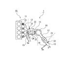
また、図15に示すような、内燃機関10の排気通路13に設けたターボ式過給器のタービン14の下流側に、上流側から順に、酸化触媒装置21、ディーゼルパティキュレートフィルタ装置(DPF)22、選択還元型NOx触媒装置(SCR)23を配置し、尿素噴射装置24を、ディーゼルパティキュレートフィルタ装置22と選択還元型NOx触媒装置23の間に設けた排気ガス浄化装置20Xを備えた排気ガス浄化システム1Xもある。
Further, as shown in FIG. 15, an
エンジンの燃焼改良が進み、燃費向上と共に、粒子状物質、窒素酸化物の総排出量も低減してきているが、その一方で、排気ガス浄化装置に流入する排気ガス温度が低くなってきている。つまり、エンジンの燃焼状態の改良の結果、排気ガス温度が従来に比べて30℃〜50℃あるいはそれ以上に低下してきていることと、排気ガス浄化装置が複数化して大型になってきていることから、熱容量が増大して触媒の活性温度を確保することが困難となってきている。 The combustion improvement of the engine has progressed and the total emission amount of particulate matter and nitrogen oxides has been reduced along with the improvement of fuel consumption. On the other hand, the temperature of exhaust gas flowing into the exhaust gas purification device has been lowered. That is, as a result of improving the combustion state of the engine, the exhaust gas temperature has decreased to 30 ° C. to 50 ° C. or more compared to the conventional technology, and multiple exhaust gas purification devices have become larger. Therefore, it has become difficult to ensure the activation temperature of the catalyst due to an increase in heat capacity.
加えて、尿素SCRシステムにおいては、尿素水を均一に拡散し、また、尿素がアンモニアに分解されるのを促進するために、尿素水噴射ノズル等の尿素供給装置から、尿素選択還元型触媒装置までの距離を短縮することが困難であり、このことも排気浄化装置が大型化する大きな要因となっている。 In addition, in the urea SCR system, a urea selective reduction catalyst device is provided from a urea supply device such as a urea water injection nozzle in order to diffuse urea water uniformly and promote decomposition of urea into ammonia. It is difficult to shorten the distance to the exhaust gas, which is a major factor in increasing the size of the exhaust purification device.
これらへの対策のひとつとして、本発明者は、排気通路の上流側から順に、前段の酸化触媒(DOC)、尿素噴射ノズル、ターボチャージャのタービン(低圧段タービン)、ディーゼルパティキュレートフィルタ(DPF)、選択還元型触媒(尿素SCR)、後段酸化触媒(R−DOC)を配置する構成により、各後処理ユニットを排気ポートに近づけて、排気ガスの熱を有効に利用して、各後処理ユニットの温度を触媒活性温度に確保し易くしたディーゼルエンジンの排気浄化装置を提案している(例えば、特許文献2参照。)。 As one of countermeasures against these problems, the present inventor, in order from the upstream side of the exhaust passage, in order from the upstream oxidation catalyst (DOC), urea injection nozzle, turbocharger turbine (low pressure stage turbine), diesel particulate filter (DPF) , A selective reduction type catalyst (urea SCR), and a post-stage oxidation catalyst (R-DOC) are arranged so that each post-treatment unit is brought close to the exhaust port and the heat of the exhaust gas is effectively used to make each post-treatment unit Has proposed an exhaust emission control device for a diesel engine that makes it easy to ensure the temperature of the catalyst at the catalyst activation temperature (see, for example, Patent Document 2).
しかしながら、排気ガスを計測するモードが、従来のJE05走行モード(都市内走行を模擬した日本の走行モード)、NEDC(ヨーロッパドライビングサイクル)走行モード等から世界統一基準のWHDC(重量車の排出ガス試験用車両サイクル)走行モード等に切り替わることで、さらにコールドモードや高温高流量における排ガス低減が必要となる状況となってきている。 However, the exhaust gas measurement mode is the world standard WHDC (Heavy Vehicle Emission Test) from the conventional JE05 driving mode (Japanese driving mode simulating urban driving), NEDC (European driving cycle) driving mode, etc. Vehicle cycle) By switching to the travel mode, etc., it has become necessary to further reduce exhaust gas in the cold mode and high temperature and high flow rate.
一方で、尿素SCRシステムに関しては、低温における窒素酸化物(NOx)浄化率の向上に関しては尿素及びその中間生成物とアンモニア(NH3)の吸着制御が検討されているが、高温かつ高流量域ではこれらの吸着制御が困難であるという問題がある。また、DPFシステムに関しては、DPF装置を通過する排気ガス温度の低下により、連続再生が可能な範囲が少なくなり、DPF装置に捕集された粒子状物質(PM)を強制的に燃焼するために排気昇温制御を行う頻度が増加し、DPF装置の強制再生時の二酸化炭素(CO2)排出量が増加するという問題がある。更には、燃料に含まれる硫黄成分から発生する硫黄酸化物(SOx)が排気ガス中に含まれていることによる排気管やターボチャージャのタービンのSOx腐食の問題もある。 On the other hand, regarding the urea SCR system, adsorption control of urea and its intermediate product and ammonia (NH 3 ) has been studied for improving the nitrogen oxide (NOx) purification rate at a low temperature. However, there is a problem that these adsorption controls are difficult. In addition, with respect to the DPF system, the temperature range of exhaust gas passing through the DPF device decreases, so the range in which continuous regeneration is possible decreases, and the particulate matter (PM) collected in the DPF device is forcibly burned. There is a problem that the frequency of exhaust gas temperature raising control increases, and the amount of carbon dioxide (CO 2 ) emission during forced regeneration of the DPF device increases. Furthermore, there is a problem of SOx corrosion of the exhaust pipe and the turbocharger turbine due to the inclusion of sulfur oxide (SOx) generated from the sulfur component contained in the fuel in the exhaust gas .
本発明は、上記の状況を鑑みてなされたものであり、その目的は、アンモニア(NH3)の生成率を向上させてNOx浄化率を向上することができると共に、DPF装置の温度を高温に保って連続再生の時間と頻度を増加して、DPF装置の強制再生及び強制再生時に発生するCO2排出量を低減でき、しかも、硫黄酸化物(SOx)によるターボチャージャのタービンの腐食を抑制することができる排気ガス浄化システム及び排気ガス浄化方法を提供することにある。 The present invention has been made in view of the above situation, and its purpose is to improve the production rate of ammonia (NH 3 ) to improve the NOx purification rate, and to increase the temperature of the DPF device. Maintaining and increasing the time and frequency of continuous regeneration to reduce CO 2 emissions generated during forced regeneration and forced regeneration of the DPF device, and also suppress the corrosion of the turbocharger turbine caused by sulfur oxide (SOx) It is an object of the present invention to provide an exhaust gas purification system and an exhaust gas purification method that can be used.
上記のような目的を達成するための本発明の排気浄化システムは、内燃機関の排気ガス中の粒子状物質、窒素酸化物を浄化する排気ガス浄化システムにおいて、前記内燃機関の排気系に、アンモニア系溶液供給装置と、該アンモニア系溶液供給装置の下流に選択還元型NOx触媒装置を配置し、前記内燃機関から排出されるNOx排出量を還元できる量を化学反応式の当量比から求め、この還元できる量よりも多い第1アンモニア系溶液量を算出すると共に、前記内燃機関のNOx目標排出量と前記選択還元型NOx触媒装置の下流側で計測されたNOx量との差から第2アンモニア系溶液量を算出し、前記第1アンモニア系溶液量と前記第2アンモニア系溶液量の和を基に前記排気系に供給するアンモニア系溶液の供給量を設定して、前記アンモニア系溶液供給装置からアンモニア系溶液を供給するアンモニア系溶液供給制御手段を備えて構成する。
また、上記の排気ガス浄化システムにおいて、前記内燃機関の排気系に、排気ポート側から順に、前段酸化触媒装置、前記アンモニア系溶液供給装置、ディーゼルパティキュレートフィルタ装置、ターボ式過給器のタービン、前記選択還元型NOx触媒装置を配置し、前記ディーゼルパティキュレートフィルタ装置の前後差圧が連続再生判定用差圧以上で自動強制再生判定用差圧以下の場合で、かつ、前記ディーゼルパティキュレートフィルタ装置の入口排気ガス温度が連続再生制御開始温度以下の場合に、筒内噴射のポスト噴射又は排気管内燃料噴射により、前記前段酸化触媒装置の上流側の排気ガス中に炭化水素を供給する制御を行う炭化水素供給制御手段を備えて構成する。
Exhaust gas purification system of the present invention for achieving the above object, an exhaust gas purification system that purifies particulate matter in the exhaust gas of an internal combustion engine, nitrogen oxides, to the exhaust system of the internal combustion engine, ammonia A selective reduction-type NOx catalyst device disposed downstream of the ammonia-based solution supply device and the ammonia-based solution supply device, and the amount capable of reducing the NOx emission amount discharged from the internal combustion engine is determined from the equivalent ratio of the chemical reaction formula, A second ammonia system is calculated from the difference between the NOx target emission amount of the internal combustion engine and the NOx amount measured on the downstream side of the selective reduction type NOx catalyst device while calculating a first ammonia solution amount that is larger than the amount that can be reduced. Calculating the amount of solution, setting the supply amount of the ammonia-based solution to be supplied to the exhaust system based on the sum of the first ammonia-based solution amount and the second ammonia-based solution amount, Configuring comprises ammonia-based solution supply control means for supplying the ammonia-based solution from ammonia-based solution supply unit.
Further, in the above exhaust gas purification system, in order from the exhaust port side to the exhaust system of the internal combustion engine, a pre-stage oxidation catalyst device, the ammonia-based solution supply device, a diesel particulate filter device, a turbocharger turbine, The selective reduction type NOx catalyst device is arranged, and the diesel particulate filter device is used when the differential pressure across the diesel particulate filter device is equal to or higher than the differential pressure for continuous regeneration determination and equal to or lower than the differential pressure for automatic forced regeneration determination. Control is performed to supply hydrocarbons into the exhaust gas upstream of the upstream oxidation catalyst device by in-cylinder injection or post-injection fuel injection when the inlet exhaust gas temperature is equal to or lower than the continuous regeneration control start temperature. A hydrocarbon supply control means is provided.
この構成によれば、DPF装置の上流側に尿素等のアンモニア系溶液を供給する尿素噴射ノズル等のアンモニア系溶液供給装置が配置されるので、このアンモニア系溶液供給装置の位置を内燃機関に近づけることができ、従来技術の配置より、アンモニア系溶液が供給される排気ガスの温度を100℃以上高く保つことができる。従って、アンモニア系溶液から生成されるNH3(アンモニア)の生成率を向上させることができる。 According to this configuration, since the ammonia-based solution supply device such as a urea injection nozzle that supplies an ammonia-based solution such as urea is disposed upstream of the DPF device, the position of the ammonia-based solution supply device is brought closer to the internal combustion engine. The temperature of the exhaust gas to which the ammonia-based solution is supplied can be kept higher by 100 ° C. or higher than the prior art arrangement. Therefore, the production rate of NH 3 (ammonia) produced from the ammonia-based solution can be improved.
また、ディーゼルパティキュレートフィルタ装置(DPF装置)をタービンよりも上流側に配置しているので、DPF装置の位置が排気ポートに近くなり、DPF装置の入口の排気ガス温度を従来技術の配置よりも100℃以上高温に保つことができ、DPF装置における連続再生の時間と頻度を増やすことができる。その結果、DPF装置の小型化が可能となり、再生時の昇温時間を短縮できて、DPF装置の再生時のCO2排出量を低減できる。それと共に、レイアウトの自由度を増すことができる。 In addition, since the diesel particulate filter device (DPF device) is disposed upstream of the turbine, the position of the DPF device is close to the exhaust port, and the exhaust gas temperature at the inlet of the DPF device is higher than that of the prior art. It can be kept at a high temperature of 100 ° C. or higher, and the time and frequency of continuous regeneration in the DPF device can be increased. As a result, the DPF device can be miniaturized, the temperature raising time during regeneration can be shortened, and the CO 2 emission amount during regeneration of the DPF device can be reduced. At the same time, the degree of freedom in layout can be increased.
更に、アンモニア系溶液供給装置、DPF装置、タービンの順に配置しているので、筒内(シリンダ内)燃焼で発生するSOx(硫黄酸化物)を、尿素噴射ノズル等のアンモニア系溶液供給装置から供給される尿素等のアンモニア系溶液から生成するNH3(アンモニア)と、DPF装置でPMを燃焼させた後に生じる灰分成分との化学反応で、腐食性の少ないCaSO4(硫酸カルシウム)にすることにより、高EGR燃焼で発生するSOxによるタービンの腐食を抑制することができる。更に、DPF装置は、タービンのオイルに由来する灰分の影響を受けない配置となっているために、この灰分によるDPF装置の目詰まりへの影響を回避できる。 Furthermore, since the ammonia-based solution supply device, the DPF device, and the turbine are arranged in this order, SOx (sulfur oxide) generated by in-cylinder (in-cylinder) combustion is supplied from an ammonia-based solution supply device such as a urea injection nozzle. By the reaction of NH 3 (ammonia) produced from ammonia-based solutions such as urea and ash components generated after PM is burned by the DPF device, it is made CaSO 4 (calcium sulfate), which is less corrosive. Moreover, corrosion of the turbine due to SOx generated by high EGR combustion can be suppressed. Furthermore, since the DPF device is arranged so as not to be affected by the ash content derived from the turbine oil, the influence of the ash content on the clogging of the DPF device can be avoided.
その上、タービンの上流側で酸化触媒装置の直後又はDPF装置直後にEGR通路を設けてEGRガスを取り出すことができるようになるので、EGR経路の短縮が可能となり、さらに、EGRガスがHC,PMが除去された後の排気ガスとなるため、EGR経路における防汚対策としても有効となる。 In addition, since the EGR passage can be taken out immediately after the oxidation catalyst device or immediately after the DPF device on the upstream side of the turbine, the EGR path can be shortened. Further, the EGR gas can be reduced to HC, Since it becomes exhaust gas after PM is removed, it is also effective as an antifouling measure in the EGR route.
上記の排気ガス浄化システムにおいて、前記ディーゼルパティキュレートフィルタ装置を、選択還元型NOx触媒を担持したディーゼルパティキュレートフィルタ装置で形成すると、このDPFと下流側の選択還元型NOx触媒装置とで、二段構えでNOxを浄化できるので、NOx浄化率を向上できる。特に、DPFに高温用選択還元型NOx触媒を担持させ、選択還元型NOx触媒装置に低温用の選択還元型NOx触媒を担持させると、低温〜高温までと高流量の広範囲においてNOx浄化率を向上できるようになる。 In the above exhaust gas purification system, when the diesel particulate filter device is formed of a diesel particulate filter device carrying a selective reduction type NOx catalyst, the DPF and the downstream selective reduction type NOx catalyst device have two stages. Since NOx can be purified by the stance, the NOx purification rate can be improved. In particular, when a DPF carries a high-temperature selective reduction type NOx catalyst and a selective reduction type NOx catalyst device carries a low-temperature selective reduction type NOx catalyst, the NOx purification rate is improved over a wide range of low flow rates to high temperatures. become able to.
また、従来技術の配置では、選択還元型NOx触媒装置(SCR装置)の上流で尿素を噴射して選択還元型NOx触媒の触媒表面に尿素、尿素中間生成物、NH3等(尿素由来物質)と、NOxを吸着させる。この尿素の噴射量はエンジンアウトのNOx量に合わせて(NH3/NO当量比1以上)制御されている。これらの制御は選択還元型NOx触媒装置の入口温度が低温(300℃以下)では有効に働くが、高温(300℃超)になると尿素由来物質とNOxは吸着後直ちに脱離するので、これらの低温と同様の吸着制御ではNOxの高浄化率は得られないという問題があった。 In the arrangement of the prior art, urea is injected upstream of the selective reduction type NOx catalyst device (SCR device) and urea, urea intermediate products, NH3, etc. (urea-derived substances) are placed on the catalyst surface of the selective reduction type NOx catalyst. , NOx is adsorbed. The urea injection amount is controlled in accordance with the NOx amount of the engine-out (NH3 / NO equivalent ratio is 1 or more). These controls work effectively when the inlet temperature of the selective reduction type NOx catalyst device is low (300 ° C or lower). However, when the temperature is high (above 300 ° C), urea-derived substances and NOx are desorbed immediately after adsorption. There is a problem that the high purification rate of NOx cannot be obtained by the adsorption control similar to the low temperature.
これに対して、本発明では、タービンの上流側に配置したDPF装置の選択還元型NOx触媒で、高温側のNOx浄化を図り、また、タービンの下流側に配置した選択還元型NOx触媒で低温側のNOx浄化を図っている。これら二段構えの選択還元型NOx触媒によるNOx浄化のために、上流側のDPF装置の選択還元型NOx触媒に対してはエンジンアウトのNOx量に対して尿素をNH3/NOの当量比が1以上1.3以下の第1アンモニア系溶液量とし、下流側の選択還元型NOx触媒装置の選択還元型NOx触媒に対しては、選択還元型NOx触媒装置の下流側のNOx排出量から不足の第2アンモニア系溶液量を算出して、これを第1アンモニア系溶液量に加えた量でアンモニア系溶液を供給する。 In contrast, in the present invention, the selective reduction type NOx catalyst of the DPF device arranged on the upstream side of the turbine purifies the high temperature side NOx, and the selective reduction type NOx catalyst arranged on the downstream side of the turbine lowers the temperature. The side is purifying NOx. In order to purify NOx by these two-stage selective reduction type NOx catalysts, for the selective reduction type NOx catalyst of the upstream DPF device, urea has an equivalent ratio of NH 3 / NO to the NOx amount of the engine out. The amount of the first ammonia-based solution is 1 or more and 1.3 or less, and the selective reduction type NOx catalyst of the downstream selective reduction type NOx catalyst device is insufficient from the downstream NOx emission amount of the selective reduction type NOx catalyst device. The amount of the second ammonia-based solution is calculated, and the ammonia-based solution is supplied in an amount that is added to the amount of the first ammonia-based solution.
そして、上記のような目的を達成するための本発明の排気浄化方法は、内燃機関の排気系に、アンモニア系溶液供給装置と、該アンモニア系溶液供給装置の下流に選択還元型NOx触媒装置を配置した構成における排気ガス浄化方法において、前記内燃機関から排出されるNOx排出量を還元できる量を化学反応式の当量比から求め、この還元できる量よりも多い第1アンモニア系溶液量を算出し、前記内燃機関のNOx目標排出量と前記選択還元型NOx触媒装置の下流側で計測されたNOx量との差から第2アンモニア系溶液量を算出し、前記第1アンモニア系溶液量と前記第2アンモニア系溶液量の和を基に前記選択還元型NOx触媒装置に供給するアンモニア系溶液の供給量を設定して、前記アンモニア系溶液供給装置から前記選択還元型NOx触媒装置にアンモニア系溶液を供給することを特徴とする方法である。 An exhaust purification method of the present invention for achieving the above object includes an ammonia-based solution supply device in an exhaust system of an internal combustion engine, and a selective reduction type NOx catalyst device downstream of the ammonia-based solution supply device. In the exhaust gas purifying method in the arrangement, the amount of NOx emitted from the internal combustion engine can be reduced from the equivalent ratio of the chemical reaction equation, and the amount of the first ammonia-based solution larger than the amount that can be reduced is calculated. the calculating a second ammonia-based solution amount from the difference between the NOx amount measured downstream of the NOx target emissions and the NOx selective reduction catalyst device of an internal combustion engine, the said first ammonia-based solution amount a the sum of 2 ammonia-based solution amount by setting the supply amount of ammonia-based solution to be supplied to the selective reduction type NOx catalyst device based on the selected from the ammonia-based solution supply unit A method characterized in that supplying ammonia-based solution based on type NOx catalyst device.
また、特に、DPFに高温用選択還元型NOx触媒を担持させ、選択還元型NOx触媒装置に低温用の選択還元型NOx触媒を担持させると、低温〜高温までと高流量の広範囲においてNOx浄化率を向上できるようになる。その結果、より適切なアンモニア系溶液の供給量となり、NOxを効率良く浄化できる。 In particular, when a high-temperature selective reduction NOx catalyst is supported on a DPF and a low-temperature selective reduction NOx catalyst is supported on a selective reduction NOx catalyst device, the NOx purification rate is wide in a wide range from low to high temperatures. Can be improved. As a result, the supply amount of the ammonia-based solution is more appropriate, and NOx can be purified efficiently.
本発明に係る排気ガス浄化システム及び排気ガス浄化方法によれば、DPF装置の上流側にアンモニア系溶液供給装置が配置されるので、このアンモニア系溶液供給装置の位置を内燃機関に近づけることができ、アンモニア系溶液が供給される排気ガスの温度を高く保つことができ、アンモニア系溶液から生成するアンモニア(NH3)の生成率を向上させることができる。 According to the exhaust gas purification system and the exhaust gas purification method of the present invention, the ammonia-based solution supply device is disposed upstream of the DPF device, so that the position of the ammonia-based solution supply device can be brought closer to the internal combustion engine. The temperature of the exhaust gas supplied with the ammonia solution can be kept high, and the production rate of ammonia (NH 3 ) produced from the ammonia solution can be improved.
更に、DPF装置をタービンよりも上流側に配置しているので、DPF装置の位置が排気ポートに近くなり、DPF装置の温度を高温に保てるため、連続再生の時間と頻度を増やすことができ、小型化が可能となる。このDPFの小型化により、再生時の昇温時間を短縮できて、DPF装置の再生時のCO2排出量を低減できると共に、レイアウトの自由度を増やすことができる。 Furthermore, since the DPF device is arranged upstream of the turbine, the position of the DPF device is close to the exhaust port, and the temperature of the DPF device can be kept high, so the time and frequency of continuous regeneration can be increased, Miniaturization is possible. By downsizing the DPF, the temperature raising time during regeneration can be shortened, the amount of CO 2 emission during regeneration of the DPF device can be reduced, and the degree of freedom in layout can be increased.
その上、アンモニア系溶液供給装置、DPF装置、タービンの順に配置しているので、筒内燃焼で発生する硫黄酸化物(SOx)を、DPF装置に捕集された粒子状物質(PM)の燃焼で発生する炭酸カルシウム(CaCO3)との反応で腐食性の少ない硫酸カルシウム(CaSO4)に変化させることができるので、DPF装置の下流側に配置されたターボチャージャのタービンの硫黄成分による腐食を抑制することができる。 In addition, since the ammonia-based solution supply device, the DPF device, and the turbine are arranged in this order, the sulfur oxide (SOx) generated by in-cylinder combustion is burned by particulate matter (PM) collected in the DPF device. Can be changed to calcium sulfate (CaSO 4 ), which is less corrosive by the reaction with calcium carbonate (CaCO 3 ) generated in the reactor, so that the corrosion by the sulfur component of the turbine of the turbocharger arranged downstream of the DPF device Can be suppressed.
更に、DPF装置はタービンの上流側に配置されて、タービンのオイルに由来する灰分の影響を受けないので、この灰分によるDPF装置の目詰まりへの影響を回避できる。 Furthermore, since the DPF device is arranged on the upstream side of the turbine and is not affected by the ash derived from the turbine oil, the influence of the ash on the clogging of the DPF device can be avoided.
さらに、炭化水素供給制御により、DPF装置の連続再生が必要とされている時に、炭化水素供給を行うことにより、DPF装置に流入する排気ガス温度を連続再生が可能な温度に上昇できるので、DPF装置における連続再生の時間や頻度を多くして、自動強制再生制御の間隔を延ばすことができ、DPF装置の強制再生時のCO2排出量を更に低減できる。 Further, when continuous regeneration of the DPF device is required by the hydrocarbon supply control, the exhaust gas temperature flowing into the DPF device can be increased to a temperature at which continuous regeneration can be performed by supplying the hydrocarbon. The time and frequency of continuous regeneration in the device can be increased to extend the automatic forced regeneration control interval, and the amount of CO 2 emission during forced regeneration of the DPF device can be further reduced.
以下、本発明に係る実施の形態の排気ガス浄化システム及び排気ガス浄化方法について、図面を参照しながら説明する。ここでは、選択還元型NOx触媒を尿素選択還元型NOx触媒とし、アンモニア系溶液を尿素とする例で示すが、これに限定されず、HC−選択還元型触媒等であってもよい。 Hereinafter, an exhaust gas purification system and an exhaust gas purification method according to embodiments of the present invention will be described with reference to the drawings. Here, an example in which the selective reduction type NOx catalyst is a urea selective reduction type NOx catalyst and the ammonia-based solution is urea is shown, but the present invention is not limited to this, and an HC-selective reduction type catalyst or the like may be used.
図1に示すように、本発明に係る実施の形態の排気ガス浄化システム1は、ディーゼルエンジン等の内燃機関(以下、エンジンという)10の排気ガスG中のPM(粒子状物質)、NOx(窒素酸化物)を浄化する排気ガス浄化システムであり、エンジン10の排気系に、エンジン本体11に接続されている排気ポート側から順に、前段酸化触媒装置(DOC)21、アンモニア系溶液供給装置である尿素噴射ノズル24、尿素選択還元型NOx触媒(SCR触媒)を担持したディーゼルパティキュレートフィルタ装置(以下、DPF装置という)22、ターボ式過給器のタービン14、選択還元型NOx触媒装置(以下、SCR装置という)23を配置して構成される。
As shown in FIG. 1, an exhaust
この前段酸化触媒装置21は、可能な限り高温の排気ガスGに接して、担持した酸化触媒の活性化温度以上の時間が長くなるように、図1に示すように、排気マニホールド12内で各排気ポートに対応させて配置される。また、必要に応じて、SCR装置23から流出してくるNH3(アンモニア)を分解するためのNH3スリップ用に、後段の酸化触媒装置(R−DOC:図示しない)をSCR装置23の下流側に配置する。
As shown in FIG. 1, each of the upstream
前段酸化触媒装置21は、CO(一酸化炭素)の浄化に優れる金属触媒と、酸素吸蔵能(OSC:Oxygen Storage capacity)を有する酸化物と酸化物半導体が混在した触媒を含む触媒層を配置して形成される。この酸素吸蔵能を有する酸化物としてはCe(セリウム)を含む酸化物があり、この酸化物半導体としてはTiO2(二酸化チタン)、ZnO(酸化亜鉛)、Y2O3(酸化イットリウム)等がある。また、この酸素吸蔵能を有する酸化物に貴金属を担持させる。
The pre-stage
また、この前段酸化触媒装置21は、排気温度およびHC(炭化水素)濃度とCO濃度により、図1に示すような排気ガス浄化システム1の単段のみの構成も可能であるが、排気ガス中のHC濃度やCO濃度が高い場合は、低温活性に優れる触媒構成が得られるように、この前段酸化触媒装置21は、第1酸化触媒装置(DOC−1)21aと第2酸化触媒装置(DOC−2)21bに分けて配置することが好ましい。この場合は、図2に示す排気ガス浄化システム1Aのように、排気マニホールド12内で排気ポートに対応させて気筒毎に第1酸化触媒装置21aを配置し、排気マニホールド12の出口の下流に第2酸化触媒装置21bを配置する。
Further, the pre-stage
この第1酸化触媒装置21aには、CO浄化に優れる金属触媒と、セリウム(Ce)を含む酸化物等のOSCを有する酸化物と、TiO2、ZnO、Y2O3等の酸化物半導体が混在した触媒を含む触媒層を配置する。また、OSCを有する酸化物に貴金属が担持される。一方、第2酸化触媒装置21bには、HC浄化に優れている白金(Pt)等の貴金属触媒若しくはHC吸着材と貴金属触媒が混在した触媒を含む触媒層を配置する。これらにより低温活性に優れた触媒構成を得ることができる。
The first
DPF装置22は、PMを捕集して除去する連続再生タイプのDPFであり、このDPF装置22には、高温におけるNOx浄化性能が高い触媒、例えば、希土類複合酸化物(Ce−Zr−O系複合酸化物等)を含む触媒で構成したSCR触媒のコート層を設けて形成することが好ましい。また、このDPF装置22においてはSCR触媒のコート後の圧力損失が増加しにくい仕様が必要となるため、気孔率や気孔径、壁厚を適正化して、浄化特性は同等でかつ圧力損失の少ない構造とする。
The
SCR装置23は、タービン14の上流に配置されるDPF装置22に担持されたSCR触媒に対して、タービン14の下流に配置されているため、例えば、図9に示すように、100℃程度の温度低下が見込まれるため、低温で尿素由来物質やNOxを吸着する機能を有するゼオライト触媒を担持させて構成することが好ましい。更には、特性触媒担体(モノリス触媒)などを用いて、比体積当たりの触媒量を増加させて従来比で50%以上低減した小型SCR装置を使用することが好ましい。
Since the
尿素噴射ノズル24は前段酸化触媒装置21より下流側でDPF装置22より上流側に設置すると、DPF装置22がタービン14よりも上流側にあるため、尿素Lがタービン14より上流側に噴射されることになり、排気ガスG中に噴射された尿素Lが、タービン14内で攪拌されて拡散するために尿素Lの加水分解や熱分解が促進される。さらには、タービン14を通過した後の排気通路13中での噴霧拡散が均一化する。このため、尿素噴射ノズル24からSCR装置23までの距離を短くすることができ、配置を近接化できる。
If the
また、NOx低減のためにEGRを行うHP−EGR通路15とLP−EGR通路16を設ける。このHP−EGR通路15は、HP(高圧)−EGRに還流するEGRガスGeを前段酸化触媒装置21(又は、図2の第1酸化触媒装置21a)通過後で、かつ、尿素噴射ノズル24の位置より前方の排気通路13から分岐する。これにより、HP−EGR通路15に前段酸化触媒装置21通過後のEGRガスGeを還流することで、HP−EGR通路15におけるEGRガス中のSOF(有機性可溶成分)を低減できるため、HP−EGR通路15のEGRクーラ(図示しない)やEGRバルブ(図示しない)の詰まり等のSOFによる影響を抑制できる。
Further, an HP-
さらに、LP(低圧)−EGRに還流するEGRガスGeはSCR触媒23の下流側から分岐する。これにより、LP−EGR通路16に前段酸化触媒装置21(又は、図2の第1酸化触媒装置21aと第2酸化触媒装置21b)、DPF装置22、SCR装置23を通過した後のEGRガスGeを還流することで、LP−EGR通路16におけるEGRガスGe中のSOF、PM、NH3を低減できるため、LP−EGR通路16のEGRクーラ(図示しない)やEGRバルブ(図示しない)の詰まり、腐食などを抑制できる。
Further, the EGR gas Ge that recirculates to LP (low pressure) -EGR branches from the downstream side of the
更に、この排気ガス浄化システム1、1Aには、DPF装置22の入口の排気ガス温度であるDPF入口温度Tを測定する温度センサ31と、DPF装置22の前後差圧ΔPを測定する差圧センサ32と、SCR装置23の下流側のNOx濃度を測定するNOx濃度センサ33を備える。更に、この温度センサ31と差圧センサ32の測定値を入力して、筒内(シリンダ内)のポスト噴射で前段酸化触媒装置21に燃料であるHC(炭化水素)を供給するHC供給制御手段と、尿素噴射ノズル24からDPF装置22とSCR装置23でNOxを還元するためのNH3を生成する尿素Lを排気ガスG中に供給する尿素供給制御手段(アンモニア系溶液供給制御手段)とを有する制御装置(図示しない)が備えられる。この制御装置は通常、エンジン10の運転全般を制御するECU(エンジンコントロールユニット)と呼ばれる制御装置(図示しない)で兼用される。即ち、HC供給制御手段と尿素供給制御手段が制御装置(ECU)に組み込まれる。
Further, the exhaust
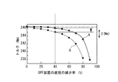
図5〜図7にタービン14の上流側にDPF装置22を配置した実施例Aとタービンの下流側にDPF装置22を配置した従来例Bを示す。実施例Aは、従来例Bに比べて、DPF圧力損失が低下し、排気マニホールド(エキゾーストマニホールド)12内の圧力が低下し、トルクが増加する。つまり、タービン膨張比の影響が無い分、実施例Aは従来例Bと比較して、DPF圧力損失の増加が排気マニホールド内圧及びトルクに及ぼす影響は相対的に小さくなる。
5 to 7 show Example A in which the
この図5〜図7から分かるように、トルク、排気マニホールド内圧等のエンジン性能に及ぼす影響を略同一にした場合に、実施例Aでは、従来例Bに比べて、DPF装置22の長さを同一とした場合にDPF装置22の直径を40%ほど小さくできる。その結果、図8に示すように、実施例Aは、従来例Bに比べて、短時間でDPF装置22を昇温できるようになり、所定温度までの昇温時間を短縮できる。
As can be seen from FIGS. 5 to 7, when the effects on the engine performance such as torque and exhaust manifold internal pressure are made substantially the same, the length of the
そして、本発明ではDPF装置22をタービン14の上流に設置することで、従来技術よりも、DPF装置22をエンジン本体11により近接して配置できる。その結果、図9に示すように、DPF入口温度Tを100℃以上高く保つことができるようになる。
In the present invention, by installing the
さらに、従来技術の場合に比べて、尿素噴射ノズル24もエンジン本体11により近接して配置できるので、図9に示すDPF入口温度Tと同様に、尿素噴射位置の温度も従来例Bよりも100℃以上高く保つことができるようになる。その結果、図10に示すように、実施例Aでは、従来例Bに比べて、SCR装置23の入口温度に対する尿素からNH3への生成率が著しく向上し、図11に示すようにタービン出口温度に対するNOx浄化率も向上する。特に尿素噴射ノズル24に対して近距離に配置されるSCR触媒を担持したDPF装置22では、このDPF装置22に流入する排気ガス温度を高くすることで、できるだけ、NH3生成率を高めて、DPF装置22のSCR触媒表面でNOxとNH3がその場で反応する効果を大きくすることができ、浄化率を向上できる。
Furthermore, since the
次に、上記の排気ガス浄化システム1、1AにおけるHC(炭化水素)供給制御について説明する。本発明では、上記の構成による優位性を踏まえて、前段酸化触媒装置21に対するHC供給制御を行い、この前段酸化触媒装置21におけるHCの吸着及び酸化により、DPF装置22に流入する排気ガスGの温度を上昇して、DPF装置22の入口の排気ガス温度であるDPF入口温度Tを連続再生が可能な温度(250℃〜500℃)にして、連続再生ができる頻度及び期間を増加させる。
Next, HC (hydrocarbon) supply control in the exhaust
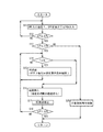
このHC供給制御は、図3に例示するような制御フローで行うことができる。この図3の制御フローは、エンジン10の運転開始と共に、起動する上位の制御フローから繰り返し呼ばれて実行され、エンジン10の運転停止と共に、制御フローを中断して上位の制御フローに戻り、上位の制御フローの停止と共に停止する制御フローとして示してある。
This HC supply control can be performed by the control flow illustrated in FIG. The control flow in FIG. 3 is repeatedly called and executed from the upper control flow to be started when the operation of the
この図3の制御フローが上位の制御フローから呼ばれてスタートすると、ステップS11で、DPF入口温度Tを温度センサ31から入力し、また、DPF装置22の前後差圧であるDPF前後差圧ΔPを差圧センサ32から入力する。次のステップS12で、DPF前後差圧ΔPが連続再生判定用差圧ΔPL以上で有るか否かを判定し、以上で有る場合(YES)は、次のステップS13で、DPF前後差圧ΔPが自動強制再生判定用差圧ΔPH以下であるか否かを判定し、以下である場合(YES)は、ステップS14に行く。
When the control flow of FIG. 3 is called from the upper control flow and starts, in step S11, the DPF inlet temperature T is input from the
なお、ステップS12の判定で、DPF前後差圧ΔPが連続再生判定用差圧ΔPL未満である場合(NO)は、ステップS11に戻る。また、ステップS13の判定で、DPF前後差圧ΔPが自動強制再生判定用差圧ΔPHより大きい場合(NO)は、ステップS20に行き、自動強制再生制御を行ってDPF装置22を強制再生した後、上位の制御フローにリターンし、この上位の制御フローから再度呼ばれて図3の制御フローが繰り返される。
If it is determined in step S12 that the differential pressure ΔP before and after the DPF is less than the differential pressure ΔPL for continuous regeneration determination (NO), the process returns to step S11. If it is determined in step S13 that the differential pressure ΔP before and after the DPF is larger than the differential pressure ΔPH for automatic forced regeneration determination (NO), the process goes to step S20 to perform automatic forced regeneration control and forcibly regenerate the
ステップS14では、DPF入口温度Tが、連続再生制御開始温度TL以下であるか否かを判定し、以下の場合(YES)にはステップS15で、HC供給を行い、ポスト噴射でHCを前段酸化触媒装置21に、所定の時間Δt1(DPF前後差圧ΔPの判定とDPF入口温度Tの判定のインターバルに関係して予め設定される時間)の間供給する。この後、ステップS14に戻る。また、ステップS14で、DPF入口温度Tが、連続再生制御開始温度TLより高い場合(NO)は、ステップS16に行く。
In step S14, it is determined whether or not the DPF inlet temperature T is equal to or lower than the continuous regeneration control start temperature TL. In the following case (YES), HC is supplied in step S15 and HC is pre-oxidized by post injection. The
ステップS16では、DPF入口温度Tが連続再生制御開始温度TLよりも大きいので、所定の時間Δt2の経過待ちを行い、この時間待ちの間にDPF装置22の連続再生を行う。その後、ステップS17に行き、HC供給を行っていれば、そのHC供給を停止し、HC供給を行っていなければ、HC供給を停止したまま、ステップS18に行く。
In step S16, since the DPF inlet temperature T is higher than the continuous regeneration control start temperature TL, the passage of a predetermined time Δt2 is waited, and the
ステップS18では、DPF前後差圧ΔPが連続再生判定用差圧ΔPL以下であるか否かを判定し、以下でない場合(NO)は、連続再生を継続するために、ステップ14に戻る。また、以下である場合(YES)は、連続再生が完了して不要になったとして、リターンし、上位の制御フローに戻り、再度この上位の制御フローから図3の制御フローが呼ばれて、再度スタートし、繰り返す。 In step S18, it is determined whether or not the differential pressure ΔP before and after the DPF is equal to or lower than the differential pressure ΔPL for continuous regeneration. If not (NO), the process returns to step 14 to continue the continuous regeneration. In the case of the following (YES), it is determined that the continuous reproduction is completed and is no longer necessary, and the process returns to the upper control flow, and the control flow of FIG. 3 is called from the upper control flow again. Start again and repeat.
このステップS11からステップS13で連続再生のための排気ガス昇温用のHC供給を行うか否かを判定し、ステップS14からステップS15の繰り返しにより、DPF入口温度Tを連続再生制御開始温度TLを超えるまで昇温する。そして、ステップS16で連続再生し、ステップS17でHC供給を停止してHCの無駄な消費を防止し、ステップS18で連続再生の終了か否かを判定する。 In step S11 to step S13, it is determined whether or not to supply HC for raising the exhaust gas for continuous regeneration. By repeating steps S14 to S15, the DPF inlet temperature T is set to the continuous regeneration control start temperature TL. Raise the temperature until it exceeds. Then, continuous reproduction is performed in step S16, HC supply is stopped in step S17 to prevent wasteful consumption of HC, and it is determined in step S18 whether or not the continuous reproduction is finished.
この図3の制御フローの実施により、DPF装置22の前後差圧ΔPが連続再生判定用差圧ΔPL以上で自動強制再生判定用差圧ΔPH以下の場合で、かつ、DPF装置22の入口排気ガス温度Tが連続再生制御開始温度TL以下の場合に、筒内噴射のポスト噴射により、前段酸化触媒装置21の上流側の排気ガスG中にHCを供給する制御を行うことができる。なお、ポスト噴射の代わりに前段酸化触媒装置21の上流側の排気管内に直接燃料噴射を行う排気管内燃料噴射を採用してもよい。
By performing the control flow of FIG. 3, the exhaust gas at the inlet of the
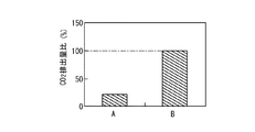
このHC供給制御により、図12に示すように、本発明の実施例Aは、DPF装置22の自動強制再生の間隔を、従来技術の従来例Bに比べて大幅に延ばすことができ、更には、図13に示すように、実施例Aは従来例Bよりも著しくDPF再生時のCO2排出量を低減できる。なお、前段酸化触媒装置21の酸化触媒にCeO2(酸化セリウム)、ZrO2(二酸化ジルコニウム)等のCOを多く吸着できる材料を使用することで、さらに前段酸化触媒装置21の発熱量を増やすことが可能である。
With this HC supply control, as shown in FIG. 12, the embodiment A of the present invention can greatly extend the interval of automatic forced regeneration of the
このHC供給制御により、DPF装置22の上流側の前段酸化触媒装置21における酸化触媒のHC吸着及び酸化の効果をより効果的に発揮でき、DPF装置22の連続再生が必要とされている時に、DPF装置22に流入する排気ガス温度(入口排気ガス温度)Tを連続再生が可能な温度TLよりも高くなるように上昇させることができるので、DPF装置22における自動強制再生制御の間隔を延ばすことができ、DPF装置22の再生時のCO2排出量を更に低減できる。
By this HC supply control, the effect of HC adsorption and oxidation of the oxidation catalyst in the upstream
次に、上記の排気ガス浄化システム1、1Aにおける尿素供給制御について説明する。本発明では、上記の構成による優位性を踏まえて、尿素噴射ノズル24から、SCR触媒を担持したDPF装置22とSCR装置23に対する尿素供給制御を行い、尿素Lから発生するNH3により、このSCR触媒を担持したDPF装置22とSCR装置23で排気ガス中のNOxを還元する。
Next, urea supply control in the exhaust
この尿素供給制御は、図4に例示するような制御フローで行うことができる。この図4の制御フローは、エンジン10の運転開始と共に起動する上位の制御フローから呼ばれて実行され、エンジン10の運転停止と共に、ステップS40の割り込みにより制御フローを中断して上位の制御フローに戻り、上位の制御フローの停止と共に停止する制御フローとして示してある。
This urea supply control can be performed by the control flow illustrated in FIG. The control flow in FIG. 4 is called and executed from the upper control flow that starts when the
この図4の制御フローが上位の制御フローから呼ばれてスタートすると、ステップS31で、第1NOx排出量Winを測定又は計算する。この第1NOx排出量Winは、エンジン本体11から排出されるNOx(NO、NO2)をNOに換算したNOx排出量(エンジンアウトのNOx排出量)であり、排気ガスG中の測定されたNOx濃度と算出された排気ガス量から求めたり、エンジン10の運転状態から予め設定されたマップデータを参照しての計算等により算出したりする。
When the control flow of FIG. 4 is called from the upper control flow and starts, the first NOx emission amount Win is measured or calculated in step S31. The first NOx emission amount Win is a NOx emission amount (NOx emission amount of engine out) obtained by converting NOx (NO, NO 2 ) emitted from the
ステップS31では、更に、この第1NOx排出量Winに対する第1尿素供給量Wumolを算出する。この第1尿素供給量Wumolは、第1NOx排出量Winに対して、NOに対するNH3の当量比を1以上1.3以下の値(実験等で求められ、予め設定された値)でNOを還元するのに必要なNH3量を算出し、このNH3量のNH3を発生する尿素量を第1尿素供給量Wumolとする。そして、尿素供給経過時間tのカウントを開始する。また、後で使用する第2尿素供給量Wuplasをゼロに設定する。 In step S31, the first urea supply amount Wumol with respect to the first NOx discharge amount Win is further calculated. This first urea supply amount Wumol is a value of 1 to 1.3 (equivalent to a preset value) of an NH 3 equivalent ratio of NO to NO with respect to the first NOx emission amount Win. The amount of NH 3 required for the reduction is calculated, and the urea amount that generates NH 3 in the amount of NH 3 is defined as the first urea supply amount Wumol. Then, the counting of the urea supply elapsed time t is started. Further, the second urea supply amount Wuplas to be used later is set to zero.
次にステップ32でカウントしている尿素供給経過時間tが予め設定した判定用時間t1を経過したか否かを判定する。この判定用時間t1は、尿素噴射ノズル24からDPF装置22の上流側の排気ガスG中に供給した尿素Lを含む排気ガスGがSCR装置23の下流側のNOx濃度センサ33に十分に到達できる時間に設定される。この時間は、実験値や排気ガス流量などからの計算値を基に設定することができる。
Next, it is determined whether or not the urea supply elapsed time t counted in
このステップS32で、尿素供給経過時間tが判定用時間t1を経過している場合(YES)は、ステップS33に行く。また、尿素供給経過時間tが判定用時間t1を経過していない場合(NO)は、ステップS34に行き、第1尿素供給量Wumolの尿素Lを、尿素噴射ノズル24からDPF装置22の上流側の排気ガスG中に、予め設定された時間(ステップS32の判定のインターバルの時間に関係する時間)Δt1の間供給する。その後、ステップS31に戻る。
If the urea supply elapsed time t has passed the determination time t1 in step S32 (YES), the process goes to step S33. If the urea supply elapsed time t has not passed the determination time t1 (NO), the process goes to step S34, and the urea L of the first urea supply amount Wumol is transferred from the
ステップS33では、SCR装置23の下流側のNOx濃度センサ33の計測値を入力し、この入力したNOx濃度と排気ガス量から測定排出量Woutを算出する。なお、排気ガス量は、エンジン10の運転状態や吸気量センサ(MAFセンサ:図示しない)で計測した吸気量と燃料噴射量から算出することができる。
In step S33, the measured value of the
この測定排出量WoutとNOx排出を低減する目標値である目標排出量WTとを比較し、測定排出量Woutが目標排出量WT以下の場合(YES)は、尿素量が第1尿素供給量Wumolで十分と判定して、ステップS34に行き、第1尿素供給量Wumolの量で尿素Lを予め設定した時間Δt1の間供給し、その後、ステップS31に戻る。 The measured discharge amount Wout is compared with the target discharge amount WT which is a target value for reducing NOx discharge. When the measured discharge amount Wout is equal to or less than the target discharge amount WT (YES), the urea amount is the first urea supply amount Wumol. Is determined to be sufficient, the process proceeds to step S34, urea L is supplied in the amount of the first urea supply amount Wumol for a preset time Δt1, and then the process returns to step S31.
一方、このステップS33の判定で測定排出量Woutが目標排出量WTより大きい場合(NO)は、尿素量が第1尿素供給量Wumolでは不十分であると判定して、ステップS35に行く。 On the other hand, if the measured discharge amount Wout is larger than the target discharge amount WT in the determination of step S33 (NO), it is determined that the urea amount is insufficient with the first urea supply amount Wumol, and the process goes to step S35.
ステップS35では、新たに測定排出量Woutを算出して、目標排出量WTと測定排出量Woutの差である排出量差Wdefを算出する(Wdef=WT−Wout)。また、この排出量差Wdefに対して、この排出量差WdefのNOx量を還元するのに必要なNH3量を算出し、このNH3量のNH3を発生する尿素量Wudを用いて第2尿素供給量Wuplasを算出する。つまり、Wuplas=Wuplas+Wudとする。これにより、排出量差Wdefを考慮した第2尿素供給量Wuplasを算出することができる。そして、更に、第1尿素供給量Wumolと第2尿素供給量Wuplasとの和である総尿素供給量Wutを算出する(Wut=Wumol+Wuplas)。 In step S35, a measured discharge amount Wout is newly calculated, and a discharge amount difference Wdef that is a difference between the target discharge amount WT and the measured discharge amount Wout is calculated (Wdef = WT−Wout). Further, the NH 3 amount required to reduce the NOx amount of the exhaust amount difference Wdef is calculated with respect to the exhaust amount difference Wdef, and the urea amount Wud that generates NH 3 of the NH 3 amount is used to calculate the NH 3 amount. The 2-urea supply amount Wuplas is calculated. That is, Wuplas = Wuplas + Wud. Thereby, the second urea supply amount Wuplas can be calculated in consideration of the discharge amount difference Wdef. Further, a total urea supply amount Wut that is the sum of the first urea supply amount Wumol and the second urea supply amount Wuplas is calculated (Wut = Wumol + Wuplas).
次のステップS36では、この総尿素供給量Wut量で尿素Lを予め設定された時間(ステップS35のNOx濃度の測定値の更新のインターバルの時間に関係する時間)Δt2の間供給し、その後、ステップS35に戻る。このステップS35〜S36を繰り返し行い、DPF装置22の上流側の排気ガスG中に総尿素供給量Wutで尿素Lを供給する。エンジン10の停止により、ステップS40の割り込みが発生すると、リターンに行き、上位の制御フローに戻り、この上位の制御フローと共に図4の制御フローを終了する。
In the next step S36, urea L is supplied at this total urea supply amount Wut amount for a preset time (time related to the update time of the measured value of NOx concentration in step S35) Δt2, and then The process returns to step S35. Steps S35 to S36 are repeated, and urea L is supplied into the exhaust gas G on the upstream side of the
上記の制御により、尿素供給経過時間tが所定の判定用時間t1を経過する前(NO)、又は、測定排出量Woutが目標排出量WT以下の場合(YES)は、ステップS31〜S34により、第1尿素供給量Wumolで、尿素Lを供給し、尿素供給経過時間tが所定の判定用時間t1を経過した後(YES)で、かつ、測定排出量Woutが目標排出量WTより大きい場合(NO)は、このステップS35〜S36により、第1尿素供給量Wumolと第2尿素供給量Wuplasの和の総尿素供給量Wutで、尿素Lを供給することができる。 By the above control, before the urea supply elapsed time t has passed the predetermined determination time t1 (NO), or when the measured discharge amount Wout is equal to or less than the target discharge amount WT (YES), steps S31 to S34 When urea L is supplied at the first urea supply amount Wumol, the urea supply elapsed time t has passed the predetermined determination time t1 (YES), and the measured discharge amount Wout is larger than the target discharge amount WT ( NO) can supply urea L at the total urea supply amount Wut, which is the sum of the first urea supply amount Wumol and the second urea supply amount Wuplas, in steps S35 to S36.
つまり、尿素供給量をタービン14の上流側のSCR触媒コートのDPF装置22で消費されるであろう尿素量を、エンジンアウトのNOx量に対して尿素をアンモニア(NH3)当量比で1以上の第1尿素供給量Wumolと考え、更に、SCR装置23の下流のNOxの測定排出量Woutを測定NOx濃度から推定して、NOxの目標排出量WTにするために不足していると推定される排出量差Wdefを算出して、タービン14の下流側のSCR装置23で消費される第2尿素供給量Wuplasを算出し、この第2尿素量Wuplasを第1尿素供給量Wumolに加えた総尿素供給量Wutで尿素Lを供給する尿素噴射制御とすることができる。
That is, the urea supply amount is assumed to be 1 or more in terms of urea (NH 3 ) equivalent ratio of urea with respect to the NOx amount of engine-out, which will be consumed by the SCR catalyst coated
その結果、図10、図11、及び、図14に示すように従来技術の従来例Bに対して、本願発明の実施例Aは低温〜高温までの広い範囲で高いNOx浄化性能を得ることができる。特に、JE05モード平均でNOx浄化率が30%以上改善される。 As a result, as shown in FIGS. 10, 11, and 14, Example A of the present invention can obtain high NOx purification performance in a wide range from low temperature to high temperature as compared with Conventional Example B of the prior art. it can. In particular, the NOx purification rate is improved by 30% or more on the JE05 mode average.
次に、DPF装置22の上流側に尿素噴射ノズル24を配置することによるSOx(硫黄酸化物)による腐食に関してのメリットについて説明する。尿素噴射ノズル24から排気ガスG中に噴霧された尿素Lは、主に尿素の熱分解反応「(NH2)2CO→NH3+HNCO」と熱分解で生成したイソシアン酸の加水分解反応「HNCO+H2O→NH3+CO2」を経てNH3(アンモニア)を発生する。この尿素から生成したNH3が排気ガス中のSOxと「2NH3+SO4→(NH4)2SO4」の反応で(NH4)2SO4(硫酸アンモニウム)を生じる。
Next, the merit regarding corrosion by SOx (sulfur oxide) by disposing the
さらに、この(NH4)2SO4が、下流側(後段)のDPF装置22でPMが燃焼した後で生じる灰分成分であるCaCO3(炭酸カルシウム)と「(NH4)2SO4+CaCO3→(NH4)2CO3+CaSO4」の反応を生じる。この生成した(NH4)2CO3(炭酸アンモニウム)は58℃以上では、熱分解反応「(NH4)2CO3→2NH3+H2O+CO2」で分解し、この反応で生じたNH3がDPF装置22の下流側のSCR装置23で捕捉されて、NOx浄化反応に使用される。
Further, this (NH 4 ) 2 SO 4 is converted into CaCO 3 (calcium carbonate) and “(NH 4 ) 2 SO 4 + CaCO 3, which are ash components generated after PM is combusted in the downstream (rear stage)
NH3とSO4等が反応して生成した(NH4)2SO4は中和物であり、腐食性が無いので、DPF装置22より下流側のタービン14や排気通路13ではSOxによる腐食の問題が解決される。また、NH3とSO4等が反応した後の排気ガスをEGRガスGeとして利用するLP(低圧)−EGRでは、EGR通路16やEGR弁(図示しない)やEGRクーラー(図示しない)の腐食の問題も解決される。
(NH 4 ) 2 SO 4 produced by the reaction of NH 3 and SO 4 is a neutralized product and is not corrosive. Therefore, in the
従って、上記の構成の排気ガス浄化システム1、1A及び排気ガス浄化方法によれば、DPF装置22の上流側に尿素噴射ノズル24が配置されるので、この尿素噴射ノズル24の位置をエンジン本体11に近づけることができ、尿素Lが供給される排気ガスGの温度を高く保つことができ、尿素Lから生成するNH3(アンモニア)の生成率を向上させることができる。
Therefore, according to the exhaust
更に、DPF装置22をタービン14よりも上流側に配置しているので、DPF装置22の位置が排気ポートに近くなり、DPF装置22の温度を高温に保てるため、連続再生の頻度を増やすことができ、小型化が可能となる。このDPF装置22の小型化により、再生時の昇温時間を短縮できて、DPF装置22の再生時のCO2排出量を低減できると共に、レイアウトの自由度を増やすことができる。
Further, since the
その上、上流側から、尿素噴射ノズル24、DPF装置22、タービン14の順に配置しているので、筒内燃焼で発生するSOxを、腐食性の少ないCaSO4にして、SOxによるタービンの腐食を抑制することができる。更に、DPF装置22は、タービン14のオイルに由来する灰分の影響を受けない配置となっているために、この灰分によるDPF装置22の目詰まりへの影響を回避できる。
In addition, since the
さらに、炭化水素供給制御を行うと、DPF装置22の連続再生が必要とされている時に、DPF装置22に流入する排気ガス温度を連続再生が可能な温度に上昇できるので、DPF装置22における自動強制再生制御の間隔を延ばすことができ、DPF装置22の再生時のCO2排出量を更に低減できる。
Further, when the hydrocarbon supply control is performed, the exhaust gas temperature flowing into the
更に、尿素供給制御により、より適切なアンモニア系溶液の供給量で尿素LをDPF装置22とSCR装置23に供給することができるので、低温から高温、かつ、高流量までの広い範囲で、NOxを効率良く浄化できるようになる。
Furthermore, since urea L can be supplied to the
従って、本発明の各排気ガス浄化ユニットの順列と炭化水素供給制御とアンモニア系溶液供給制御を合わせて、低温・低流量から高温・高流量の広い範囲でNOx浄化率を向上できる。 Accordingly, by combining the permutation of each exhaust gas purification unit of the present invention, the hydrocarbon supply control, and the ammonia-based solution supply control, the NOx purification rate can be improved over a wide range from low temperature / low flow rate to high temperature / high flow rate.
本発明の排気ガス浄化システム及び排気ガス浄化方法によれば、アンモニア系水溶液供給装置の位置をエンジン本体の排気ポートに近づけて配置して、尿素が供給される排気ガスの温度を高く保つことにより、アンモニア(NH3)の生成率を向上させてNOx浄化率を向上することができ、それと共に、DPF装置もエンジン本体の排気ポートに近づけて配置して、DPF装置の温度を高温に保つことにより、DPF装置の連続再生の時間や頻度を増加して、DPF装置の強制再生及び強制再生時に発生するCO2排出量を低減でき、しかも、アンモニア系水溶液供給装置、DPF、タービンの順列で配置して、排気ガス中の硫黄酸化物(SOx)をDPFの灰分と反応させて、腐食性の少ない硫酸カルシウムに変化させてからタービンに流入させることにより、硫黄酸化物によるターボチャージャのタービンの腐食を抑制することができるので、自動車等に搭載した内燃機関等の排気ガス浄化システム及び排気ガス浄化方法として利用できる。 According to the exhaust gas purification system and the exhaust gas purification method of the present invention, the temperature of the exhaust gas supplied with urea is kept high by arranging the ammonia-based aqueous solution supply device close to the exhaust port of the engine body. The NOx purification rate can be improved by improving the production rate of ammonia (NH 3 ), and at the same time, the DPF device is also placed close to the exhaust port of the engine body to keep the temperature of the DPF device high. By increasing the time and frequency of continuous regeneration of the DPF device, CO 2 emissions generated during forced regeneration and forced regeneration of the DPF device can be reduced, and in addition, the ammonia-based aqueous solution supply device, the DPF, and the turbine are arranged in a permutation. to sulfur oxides in the exhaust gas (SOx) is reacted with ash DPF, the turbines by changing the low calcium sulfate corrosive By entering, it is possible to suppress corrosion of the turbine of the turbocharger by sulfur oxides, it can be used as an exhaust gas purification system and an exhaust gas purification method, such as equipped with an internal combustion engine in an automobile or the like.
1、1A 排気ガス浄化システム
10 内燃機関(エンジン)
11 エンジン本体
12 排気マニホールド
13 排気通路
14 ターボ式過給器のタービン
15 HP−EGR通路
16 LP−EGR通路
21 前段酸化触媒装置(DOC)
21a 第1酸化触媒装置(DOC−1)
21b 第2酸化触媒装置(DOC−2)
22 ディーゼルパティキュレートフィルタ装置(DPF装置)
23 選択還元型NOx触媒装置(SCR装置)
24 尿素噴射ノズル(アンモニア系溶液供給装置)
31 温度センサ
32 差圧センサ
33 NOx濃度センサ
G 排気ガス
Ge EGRガス
L 尿素
T DPF入口温度
ΔP DPF装置の前後差圧
1, 1A Exhaust
DESCRIPTION OF
21a First oxidation catalyst device (DOC-1)
21b Second oxidation catalyst device (DOC-2)
22 Diesel particulate filter device (DPF device)
23 Selective reduction type NOx catalyst device (SCR device)
24 Urea injection nozzle (ammonia-based solution supply device)
31
Claims (4)
前記内燃機関から排出されるNOx排出量を還元できる量を化学反応式の当量比から求め、この還元できる量よりも多い第1アンモニア系溶液量を算出すると共に、前記内燃機関のNOx目標排出量と前記選択還元型NOx触媒装置の下流側で計測されたNOx量との差から第2アンモニア系溶液量を算出し、前記第1アンモニア系溶液量と前記第2アンモニア系溶液量の和を基に前記排気系に供給するアンモニア系溶液の供給量を設定して、前記アンモニア系溶液供給装置からアンモニア系溶液を供給するアンモニア系溶液供給制御手段を備えた排気ガス浄化システム。 In an exhaust gas purification system for purifying particulate matter and nitrogen oxides in exhaust gas of an internal combustion engine, an ammonia-based solution supply device is provided in the exhaust system of the internal combustion engine, and a selective reduction type is provided downstream of the ammonia-based solution supply device. NOx catalyst device is arranged,
An amount capable of reducing the NOx emission amount discharged from the internal combustion engine is obtained from an equivalence ratio of the chemical reaction formula, and a first ammonia-based solution amount larger than the reduction amount is calculated, and the NOx target emission amount of the internal combustion engine is calculated. And the second ammonia-based solution amount is calculated from the difference between the NOx amount measured on the downstream side of the selective reduction-type NOx catalyst device and based on the sum of the first ammonia-based solution amount and the second ammonia-based solution amount. An exhaust gas purification system comprising ammonia-based solution supply control means for setting the supply amount of the ammonia-based solution to be supplied to the exhaust system and supplying the ammonia-based solution from the ammonia-based solution supply device.
前記ディーゼルパティキュレートフィルタ装置の前後差圧が連続再生判定用差圧以上で自動強制再生判定用差圧以下の場合で、かつ、前記ディーゼルパティキュレートフィルタ装置の入口排気ガス温度が連続再生制御開始温度以下の場合に、筒内噴射のポスト噴射又は排気管内燃料噴射により、前記前段酸化触媒装置の上流側の排気ガス中に炭化水素を供給する制御を行う炭化水素供給制御手段を備えたことを特徴とする請求項1に記載の排気ガス浄化システム。 In the exhaust system of the internal combustion engine, a pre-stage oxidation catalyst device, the ammonia-based solution supply device, a diesel particulate filter device, a turbocharger turbine, and the selective reduction NOx catalyst device are arranged in this order from the exhaust port side. ,
When the differential pressure before and after the diesel particulate filter device is equal to or higher than the differential pressure for continuous regeneration determination and equal to or lower than the differential pressure for automatic forced regeneration determination, and the exhaust gas temperature at the inlet of the diesel particulate filter device is the continuous regeneration control start temperature In the following cases, it is provided with hydrocarbon supply control means for performing control to supply hydrocarbons into the exhaust gas upstream of the upstream oxidation catalyst device by in-cylinder injection post injection or exhaust pipe fuel injection. The exhaust gas purification system according to claim 1.
前記内燃機関から排出されるNOx排出量を還元できる量を化学反応式の当量比から求め、この還元できる量よりも多い第1アンモニア系溶液量を算出し、
前記内燃機関のNOx目標排出量と前記選択還元型NOx触媒装置の下流側で計測されたNOx量との差から第2アンモニア系溶液量を算出し、
前記第1アンモニア系溶液量と前記第2アンモニア系溶液量の和を基に前記選択還元型NOx触媒装置に供給するアンモニア系溶液の供給量を設定して、
前記アンモニア系溶液供給装置から前記選択還元型NOx触媒装置にアンモニア系溶液を供給することを特徴とする排気ガス浄化方法。 In an exhaust gas purification method in a configuration in which an ammonia-based solution supply device is disposed in an exhaust system of an internal combustion engine, and a selective reduction type NOx catalyst device is disposed downstream of the ammonia-based solution supply device,
An amount capable of reducing the NOx emission amount discharged from the internal combustion engine is obtained from the equivalent ratio of the chemical reaction formula, and the amount of the first ammonia-based solution larger than the amount that can be reduced is calculated.
Wherein calculating a second ammonia-based solution amount from the difference between the NOx amount measured downstream of the NOx target emissions and the NOx selective reduction catalyst device of an internal combustion engine,
Based on the sum of the first ammonia solution amount and the second ammonia solution amount, the supply amount of the ammonia solution to be supplied to the selective reduction type NOx catalyst device is set,
Exhaust gas purification method, characterized in that to supply the ammonia-based solution to the selective reduction type NOx catalyst device from the ammonia-based solution supply unit.
Priority Applications (5)
| Application Number | Priority Date | Filing Date | Title |
|---|---|---|---|
| JP2012109143A JP6074912B2 (en) | 2012-05-11 | 2012-05-11 | Exhaust gas purification system and exhaust gas purification method |
| CN201380023745.3A CN104285049B (en) | 2012-05-11 | 2013-05-02 | Exhaust gas purification system and exhaust gas purification method |
| EP13787528.2A EP2853707B1 (en) | 2012-05-11 | 2013-05-02 | Exhaust gas purification method |
| PCT/JP2013/062771 WO2013168677A1 (en) | 2012-05-11 | 2013-05-02 | Exhaust gas purification system and exhaust gas purification method |
| US14/395,540 US9593614B2 (en) | 2012-05-11 | 2013-05-02 | Exhaust gas purification system and exhaust gas purification method |
Applications Claiming Priority (1)
| Application Number | Priority Date | Filing Date | Title |
|---|---|---|---|
| JP2012109143A JP6074912B2 (en) | 2012-05-11 | 2012-05-11 | Exhaust gas purification system and exhaust gas purification method |
Publications (2)
| Publication Number | Publication Date |
|---|---|
| JP2013234639A JP2013234639A (en) | 2013-11-21 |
| JP6074912B2 true JP6074912B2 (en) | 2017-02-08 |
Family
ID=49550715
Family Applications (1)
| Application Number | Title | Priority Date | Filing Date |
|---|---|---|---|
| JP2012109143A Expired - Fee Related JP6074912B2 (en) | 2012-05-11 | 2012-05-11 | Exhaust gas purification system and exhaust gas purification method |
Country Status (5)
| Country | Link |
|---|---|
| US (1) | US9593614B2 (en) |
| EP (1) | EP2853707B1 (en) |
| JP (1) | JP6074912B2 (en) |
| CN (1) | CN104285049B (en) |
| WO (1) | WO2013168677A1 (en) |
Families Citing this family (19)
| Publication number | Priority date | Publication date | Assignee | Title |
|---|---|---|---|---|
| WO2014087536A1 (en) * | 2012-12-07 | 2014-06-12 | トヨタ自動車株式会社 | Device for detecting fault in exhaust gas purifier |
| DE102014005244A1 (en) * | 2014-04-08 | 2015-10-08 | Man Diesel & Turbo Se | Exhaust after-treatment system and exhaust aftertreatment process |
| JP6187385B2 (en) * | 2014-05-26 | 2017-08-30 | トヨタ自動車株式会社 | Exhaust gas purification device for internal combustion engine |
| EP3194736A1 (en) * | 2014-08-25 | 2017-07-26 | Haldor Topsøe A/S | Method and system for the removal of particulate matter and heavy metals from engine exhaust gas |
| EP3168450A1 (en) * | 2015-11-12 | 2017-05-17 | Winterthur Gas & Diesel Ltd. | Internal combustion engine, method for cleaning exhaust from an internal combustion engine and method for refitting an internal combustion engine |
| CN105422220A (en) * | 2015-12-10 | 2016-03-23 | 广西玉柴机器股份有限公司 | Post-processing system of diesel engine |
| JP2017110499A (en) * | 2015-12-14 | 2017-06-22 | いすゞ自動車株式会社 | Exhaust emission control system for internal combustion engine and exhaust emission control method for internal combustion engine |
| WO2017101965A1 (en) * | 2015-12-14 | 2017-06-22 | Volvo Truck Corporation | An internal combustion engine system and a method for an internal combustion engine system |
| JP6394616B2 (en) * | 2016-01-22 | 2018-09-26 | トヨタ自動車株式会社 | Exhaust gas purification device for internal combustion engine |
| KR101836282B1 (en) * | 2016-10-20 | 2018-03-08 | 현대자동차 주식회사 | Exhaust system with differential pressure sensor |
| FR3061514A1 (en) * | 2017-01-05 | 2018-07-06 | Peugeot Citroen Automobiles Sa | METHOD OF DECRASSING AN EXHAUST LINE OF AN INTERNAL COMBUSTION ENGINE |
| JP6607236B2 (en) * | 2017-07-04 | 2019-11-20 | トヨタ自動車株式会社 | Exhaust system for internal combustion engine |
| DE102017128853A1 (en) | 2017-12-05 | 2019-06-06 | Volkswagen Aktiengesellschaft | Exhaust after-treatment system for an internal combustion engine and method for operating an internal combustion engine |
| WO2019129369A1 (en) * | 2017-12-29 | 2019-07-04 | Volvo Truck Corporation | A start-up method for a vehicle with a hybrid propulsion system |
| NL2020739B1 (en) | 2018-04-10 | 2019-10-16 | Daf Trucks Nv | Pro-Active Thermal Measure to recover and or retain deNOx performance |
| CN112005000B (en) * | 2018-04-16 | 2022-06-21 | 沃尔沃卡车集团 | Internal combustion engine arrangement |
| WO2020108725A1 (en) | 2018-11-26 | 2020-06-04 | Volvo Truck Corporation | An aftertreatment system |
| US11834978B2 (en) * | 2019-07-30 | 2023-12-05 | Cummins Emission Solutions Inc. | Systems and methods for decreasing time to reach light-off temperature |
| CN111350576A (en) * | 2020-03-18 | 2020-06-30 | 广西玉柴机器股份有限公司 | DPF tightens coupled after-treatment system before whirlpool |
Family Cites Families (23)
| Publication number | Priority date | Publication date | Assignee | Title |
|---|---|---|---|---|
| JP3876705B2 (en) * | 2001-12-13 | 2007-02-07 | いすゞ自動車株式会社 | Diesel engine exhaust gas purification system |
| JP2003214144A (en) * | 2002-01-18 | 2003-07-30 | Mitsubishi Motors Corp | Particulate purification device |
| DE10300298A1 (en) * | 2003-01-02 | 2004-07-15 | Daimlerchrysler Ag | Exhaust gas aftertreatment device and method |
| DE202005001257U1 (en) * | 2004-09-17 | 2005-04-07 | Arvinmeritor Emissions Tech | Exhaust system of a motor vehicle with diesel engine |
| EP2126297B1 (en) * | 2007-02-21 | 2015-01-28 | Volvo Lastvagnar AB | Method for operating an exhaust aftertreatment system and exhaust aftertreatment system |
| JP4100451B1 (en) * | 2007-03-02 | 2008-06-11 | いすゞ自動車株式会社 | Exhaust gas purification method and exhaust gas purification system |
| JP4928335B2 (en) * | 2007-04-17 | 2012-05-09 | 日野自動車株式会社 | Exhaust purification device |
| DE102007032736A1 (en) * | 2007-07-13 | 2009-01-15 | Emitec Gesellschaft Für Emissionstechnologie Mbh | Exhaust gas aftertreatment in front of a turbocharger |
| US20090077954A1 (en) * | 2007-09-24 | 2009-03-26 | Winsor Richard E | Continuously regenerating particulate filter for internal combustion engine |
| JP4726926B2 (en) * | 2008-05-22 | 2011-07-20 | 株式会社デンソー | Exhaust gas purification device for internal combustion engine |
| JP2010090796A (en) * | 2008-10-08 | 2010-04-22 | Hino Motors Ltd | Exhaust gas treatment device |
| JP2010242515A (en) | 2009-04-01 | 2010-10-28 | Isuzu Motors Ltd | Exhaust emission control system and exhaust emission control method |
| WO2010151690A2 (en) * | 2009-06-24 | 2010-12-29 | Cummins Ip, Inc. | APPARATUS, SYSTEM, AND METHOD FOR ESTIMATING DETERIORATION OF A NOx SENSOR RESPONSE RATE |
| JP2011094495A (en) * | 2009-10-27 | 2011-05-12 | Nippon Soken Inc | Exhaust emission control system |
| JP5763294B2 (en) * | 2009-11-25 | 2015-08-12 | いすゞ自動車株式会社 | Exhaust purification equipment |
| US8347611B2 (en) * | 2009-12-23 | 2013-01-08 | Ford Global Technologies, Llc | Methods and systems for emission system control |
| US8516799B2 (en) * | 2009-12-23 | 2013-08-27 | Ford Global Technologies, Llc | Methods and systems for emission system control |
| JP5630024B2 (en) | 2010-01-25 | 2014-11-26 | いすゞ自動車株式会社 | Diesel engine exhaust purification device and exhaust purification method |
| WO2011118095A1 (en) * | 2010-03-25 | 2011-09-29 | Udトラックス株式会社 | Engine exhaust purification device and engine exaust purification method |
| JP5440384B2 (en) * | 2010-05-25 | 2014-03-12 | いすゞ自動車株式会社 | Exhaust gas purification system |
| WO2012129179A1 (en) * | 2011-03-18 | 2012-09-27 | Cummins Inc. | A method and apparatus to control selective catalytic reduction systems in feedback |
| US8973351B2 (en) * | 2011-11-29 | 2015-03-10 | Kubota Corporation | Work machine |
| JP2013189900A (en) * | 2012-03-13 | 2013-09-26 | Isuzu Motors Ltd | Exhaust gas purification device |
-
2012
- 2012-05-11 JP JP2012109143A patent/JP6074912B2/en not_active Expired - Fee Related
-
2013
- 2013-05-02 US US14/395,540 patent/US9593614B2/en active Active
- 2013-05-02 EP EP13787528.2A patent/EP2853707B1/en active Active
- 2013-05-02 CN CN201380023745.3A patent/CN104285049B/en active Active
- 2013-05-02 WO PCT/JP2013/062771 patent/WO2013168677A1/en active Application Filing
Also Published As
| Publication number | Publication date |
|---|---|
| JP2013234639A (en) | 2013-11-21 |
| US9593614B2 (en) | 2017-03-14 |
| EP2853707B1 (en) | 2017-08-23 |
| US20150128576A1 (en) | 2015-05-14 |
| CN104285049B (en) | 2017-04-26 |
| EP2853707A1 (en) | 2015-04-01 |
| WO2013168677A1 (en) | 2013-11-14 |
| EP2853707A4 (en) | 2015-12-23 |
| CN104285049A (en) | 2015-01-14 |
Similar Documents
| Publication | Publication Date | Title |
|---|---|---|
| JP6074912B2 (en) | Exhaust gas purification system and exhaust gas purification method | |
| WO2013172215A1 (en) | Exhaust gas purification system and method for purifying exhaust gas | |
| JP5630024B2 (en) | Diesel engine exhaust purification device and exhaust purification method | |
| US8056323B2 (en) | Method of controlling exhaust gas purification system and exhaust gas purification system | |
| Alkemade et al. | Engines and exhaust after treatment systems for future automotive applications | |
| WO2013137309A1 (en) | Exhaust gas purification device | |
| JP5630025B2 (en) | Diesel engine exhaust purification device and exhaust purification method | |
| KR101509689B1 (en) | System for purifying exhaust gas and exhaust system having the same | |
| KR20130087146A (en) | Apparatus and controlling method of urea-scr system | |
| JP2013142363A (en) | Exhaust emission control device of diesel engine | |
| US9702286B2 (en) | Exhaust gas purification system and exhaust gas purification method | |
| CA2527006A1 (en) | System and method of controlling reductant addition | |
| US20130232953A1 (en) | Exhaust-gas aftertreatment system and method for exhaust-gas aftertreatment | |
| US20170276053A1 (en) | After-Treatment System | |
| JP2012159054A (en) | Exhaust gas purification system for internal combustion engine | |
| EP2410144B1 (en) | Method of Controlling NOx Emissions in an Internal Combustion Engine | |
| Johansen et al. | Passive no 2 regeneration and nox conversion for dpf with an integrated vanadium scr catalyst | |
| WO2018057170A1 (en) | After-treatment system | |
| Yoon et al. | Study of NO storage and reduction on LNT by micro bench-flow reactor |
Legal Events
| Date | Code | Title | Description |
|---|---|---|---|
| A621 | Written request for application examination |
Free format text: JAPANESE INTERMEDIATE CODE: A621 Effective date: 20150424 |
|
| A131 | Notification of reasons for refusal |
Free format text: JAPANESE INTERMEDIATE CODE: A131 Effective date: 20160119 |
|
| A521 | Request for written amendment filed |
Free format text: JAPANESE INTERMEDIATE CODE: A523 Effective date: 20160318 |
|
| A131 | Notification of reasons for refusal |
Free format text: JAPANESE INTERMEDIATE CODE: A131 Effective date: 20160906 |
|
| A521 | Request for written amendment filed |
Free format text: JAPANESE INTERMEDIATE CODE: A523 Effective date: 20161104 |
|
| TRDD | Decision of grant or rejection written | ||
| A01 | Written decision to grant a patent or to grant a registration (utility model) |
Free format text: JAPANESE INTERMEDIATE CODE: A01 Effective date: 20161213 |
|
| A61 | First payment of annual fees (during grant procedure) |
Free format text: JAPANESE INTERMEDIATE CODE: A61 Effective date: 20161226 |
|
| R150 | Certificate of patent or registration of utility model |
Ref document number: 6074912 Country of ref document: JP Free format text: JAPANESE INTERMEDIATE CODE: R150 |
|
| LAPS | Cancellation because of no payment of annual fees |