EP2125501B1 - Wave power - Google Patents
Wave power Download PDFInfo
- Publication number
- EP2125501B1 EP2125501B1 EP08726305.9A EP08726305A EP2125501B1 EP 2125501 B1 EP2125501 B1 EP 2125501B1 EP 08726305 A EP08726305 A EP 08726305A EP 2125501 B1 EP2125501 B1 EP 2125501B1
- Authority
- EP
- European Patent Office
- Prior art keywords
- float
- tether
- wpv
- swimmer
- cable
- Prior art date
- Legal status (The legal status is an assumption and is not a legal conclusion. Google has not performed a legal analysis and makes no representation as to the accuracy of the status listed.)
- Active
Links
- XLYOFNOQVPJJNP-UHFFFAOYSA-N water Substances O XLYOFNOQVPJJNP-UHFFFAOYSA-N 0.000 claims description 42
- 230000033001 locomotion Effects 0.000 claims description 15
- 230000008878 coupling Effects 0.000 claims description 9
- 238000010168 coupling process Methods 0.000 claims description 9
- 238000005859 coupling reaction Methods 0.000 claims description 9
- 239000004020 conductor Substances 0.000 claims description 8
- 239000000203 mixture Substances 0.000 claims description 8
- 239000011295 pitch Substances 0.000 claims description 8
- 238000007667 floating Methods 0.000 claims description 6
- 201000009482 yaws Diseases 0.000 claims description 4
- 238000007689 inspection Methods 0.000 claims description 3
- 238000000465 moulding Methods 0.000 claims description 2
- 239000013307 optical fiber Substances 0.000 claims description 2
- CURLTUGMZLYLDI-UHFFFAOYSA-N Carbon dioxide Chemical compound O=C=O CURLTUGMZLYLDI-UHFFFAOYSA-N 0.000 description 16
- 229910002092 carbon dioxide Inorganic materials 0.000 description 8
- 239000001569 carbon dioxide Substances 0.000 description 8
- 238000000034 method Methods 0.000 description 6
- 230000008859 change Effects 0.000 description 5
- 125000004432 carbon atom Chemical group C* 0.000 description 4
- RYGMFSIKBFXOCR-UHFFFAOYSA-N Copper Chemical compound [Cu] RYGMFSIKBFXOCR-UHFFFAOYSA-N 0.000 description 3
- 229920000271 Kevlar® Polymers 0.000 description 3
- 238000004891 communication Methods 0.000 description 3
- 230000004907 flux Effects 0.000 description 3
- 239000004761 kevlar Substances 0.000 description 3
- 239000000463 material Substances 0.000 description 3
- 238000005259 measurement Methods 0.000 description 3
- 230000007246 mechanism Effects 0.000 description 3
- 229910001220 stainless steel Inorganic materials 0.000 description 3
- 239000010935 stainless steel Substances 0.000 description 3
- 229920002994 synthetic fiber Polymers 0.000 description 3
- 239000012209 synthetic fiber Substances 0.000 description 3
- 239000004812 Fluorinated ethylene propylene Substances 0.000 description 2
- 229920000508 Vectran Polymers 0.000 description 2
- 239000004979 Vectran Substances 0.000 description 2
- 230000008901 benefit Effects 0.000 description 2
- 229910052802 copper Inorganic materials 0.000 description 2
- 239000010949 copper Substances 0.000 description 2
- 230000007423 decrease Effects 0.000 description 2
- 230000003247 decreasing effect Effects 0.000 description 2
- 239000002184 metal Substances 0.000 description 2
- 229910052751 metal Inorganic materials 0.000 description 2
- 229920009441 perflouroethylene propylene Polymers 0.000 description 2
- -1 polytetrafluoroethylene Polymers 0.000 description 2
- 229920001343 polytetrafluoroethylene Polymers 0.000 description 2
- 239000004810 polytetrafluoroethylene Substances 0.000 description 2
- 239000004814 polyurethane Substances 0.000 description 2
- 229920002635 polyurethane Polymers 0.000 description 2
- 230000001960 triggered effect Effects 0.000 description 2
- 229910000619 316 stainless steel Inorganic materials 0.000 description 1
- 241000283153 Cetacea Species 0.000 description 1
- 229910000881 Cu alloy Inorganic materials 0.000 description 1
- 239000004677 Nylon Substances 0.000 description 1
- 239000000654 additive Substances 0.000 description 1
- 239000004760 aramid Substances 0.000 description 1
- 229920003235 aromatic polyamide Polymers 0.000 description 1
- 125000003118 aryl group Chemical group 0.000 description 1
- 238000005452 bending Methods 0.000 description 1
- 238000005266 casting Methods 0.000 description 1
- 238000012512 characterization method Methods 0.000 description 1
- 150000001875 compounds Chemical class 0.000 description 1
- 238000010276 construction Methods 0.000 description 1
- 238000013480 data collection Methods 0.000 description 1
- 238000013461 design Methods 0.000 description 1
- 239000003822 epoxy resin Substances 0.000 description 1
- HQQADJVZYDDRJT-UHFFFAOYSA-N ethene;prop-1-ene Chemical group C=C.CC=C HQQADJVZYDDRJT-UHFFFAOYSA-N 0.000 description 1
- 210000003746 feather Anatomy 0.000 description 1
- 229920002313 fluoropolymer Polymers 0.000 description 1
- 239000004615 ingredient Substances 0.000 description 1
- 238000009434 installation Methods 0.000 description 1
- 238000009413 insulation Methods 0.000 description 1
- 239000007788 liquid Substances 0.000 description 1
- 229920001778 nylon Polymers 0.000 description 1
- 239000004033 plastic Substances 0.000 description 1
- 229920003023 plastic Polymers 0.000 description 1
- 229920000647 polyepoxide Polymers 0.000 description 1
- 229920000728 polyester Polymers 0.000 description 1
- 229920000642 polymer Polymers 0.000 description 1
- 238000004382 potting Methods 0.000 description 1
- 230000008569 process Effects 0.000 description 1
- 238000000926 separation method Methods 0.000 description 1
- 229910000679 solder Inorganic materials 0.000 description 1
- 239000007921 spray Substances 0.000 description 1
- 238000012360 testing method Methods 0.000 description 1
Images


Classifications
-
- B—PERFORMING OPERATIONS; TRANSPORTING
- B63—SHIPS OR OTHER WATERBORNE VESSELS; RELATED EQUIPMENT
- B63H—MARINE PROPULSION OR STEERING
- B63H19/00—Marine propulsion not otherwise provided for
- B63H19/02—Marine propulsion not otherwise provided for by using energy derived from movement of ambient water, e.g. from rolling or pitching of vessels
-
- B—PERFORMING OPERATIONS; TRANSPORTING
- B63—SHIPS OR OTHER WATERBORNE VESSELS; RELATED EQUIPMENT
- B63B—SHIPS OR OTHER WATERBORNE VESSELS; EQUIPMENT FOR SHIPPING
- B63B21/00—Tying-up; Shifting, towing, or pushing equipment; Anchoring
- B63B21/56—Towing or pushing equipment
- B63B21/66—Equipment specially adapted for towing underwater objects or vessels, e.g. fairings for tow-cables
-
- F—MECHANICAL ENGINEERING; LIGHTING; HEATING; WEAPONS; BLASTING
- F03—MACHINES OR ENGINES FOR LIQUIDS; WIND, SPRING, OR WEIGHT MOTORS; PRODUCING MECHANICAL POWER OR A REACTIVE PROPULSIVE THRUST, NOT OTHERWISE PROVIDED FOR
- F03B—MACHINES OR ENGINES FOR LIQUIDS
- F03B13/00—Adaptations of machines or engines for special use; Combinations of machines or engines with driving or driven apparatus; Power stations or aggregates
- F03B13/12—Adaptations of machines or engines for special use; Combinations of machines or engines with driving or driven apparatus; Power stations or aggregates characterised by using wave or tide energy
- F03B13/14—Adaptations of machines or engines for special use; Combinations of machines or engines with driving or driven apparatus; Power stations or aggregates characterised by using wave or tide energy using wave energy
-
- B—PERFORMING OPERATIONS; TRANSPORTING
- B63—SHIPS OR OTHER WATERBORNE VESSELS; RELATED EQUIPMENT
- B63B—SHIPS OR OTHER WATERBORNE VESSELS; EQUIPMENT FOR SHIPPING
- B63B35/00—Vessels or similar floating structures specially adapted for specific purposes and not otherwise provided for
- B63B35/44—Floating buildings, stores, drilling platforms, or workshops, e.g. carrying water-oil separating devices
- B63B2035/4433—Floating structures carrying electric power plants
- B63B2035/4466—Floating structures carrying electric power plants for converting water energy into electric energy, e.g. from tidal flows, waves or currents
-
- Y—GENERAL TAGGING OF NEW TECHNOLOGICAL DEVELOPMENTS; GENERAL TAGGING OF CROSS-SECTIONAL TECHNOLOGIES SPANNING OVER SEVERAL SECTIONS OF THE IPC; TECHNICAL SUBJECTS COVERED BY FORMER USPC CROSS-REFERENCE ART COLLECTIONS [XRACs] AND DIGESTS
- Y02—TECHNOLOGIES OR APPLICATIONS FOR MITIGATION OR ADAPTATION AGAINST CLIMATE CHANGE
- Y02E—REDUCTION OF GREENHOUSE GAS [GHG] EMISSIONS, RELATED TO ENERGY GENERATION, TRANSMISSION OR DISTRIBUTION
- Y02E10/00—Energy generation through renewable energy sources
- Y02E10/30—Energy from the sea, e.g. using wave energy or salinity gradient
-
- Y—GENERAL TAGGING OF NEW TECHNOLOGICAL DEVELOPMENTS; GENERAL TAGGING OF CROSS-SECTIONAL TECHNOLOGIES SPANNING OVER SEVERAL SECTIONS OF THE IPC; TECHNICAL SUBJECTS COVERED BY FORMER USPC CROSS-REFERENCE ART COLLECTIONS [XRACs] AND DIGESTS
- Y02—TECHNOLOGIES OR APPLICATIONS FOR MITIGATION OR ADAPTATION AGAINST CLIMATE CHANGE
- Y02T—CLIMATE CHANGE MITIGATION TECHNOLOGIES RELATED TO TRANSPORTATION
- Y02T70/00—Maritime or waterways transport
- Y02T70/50—Measures to reduce greenhouse gas emissions related to the propulsion system
- Y02T70/5218—Less carbon-intensive fuels, e.g. natural gas, biofuels
- Y02T70/5236—Renewable or hybrid-electric solutions
Definitions
- This invention relates to devices which are subject to waves in the water, and which in some cases utilize the power of waves in water.
- a wave travels along the surface of water, it produces vertical motion, but no net horizontal motion, of water.
- the amplitude of the vertical motion decreases logarithmically with depth; at a depth of about half the wave length, there is little vertical motion.
- the speed of currents induced by wind also decreases sharply with depth.
- a number of proposals have been made to utilize wave power to do useful work. Reference may be made, for example, to U.S. Patent Nos.
- WPV wave powered vehicle
- the vehicle comprises (1) a float, (2) a swimmer, and (3) a tether connecting the float and the swimmer; the float, swimmer and tether being such that, when the vehicle is in still water, (i) the float is on or near the surface of the water, (ii) the swimmer is submerged below the float, and (iii) the tether is under tension; and the swimmer, when the vehicle is in wave-bearing water, interacting with the water to generate forces which tend to move the float in a direction having a horizontal component (hereinafter referred to simply as "in a horizontal direction" or "horizontally)".
- the upper member has a height which can be changed (for example comprises components which can telescope into each other, and/or comprises one or more components which can fold and unfold).
- this invention provides a cable which
- this invention provides a WPV which comprises means for determining whether the tether is twisted.
- this invention provides a WPV which comprises means for untwisting the tether when the tether is twisted.
- this invention provides a WPV which comprises a pressure-sensitive connection which causes the tether to separate from float and/or from the swimmer, and/or causes the tether to break, when the water pressure substantially exceeds the water pressure under normal conditions of use. In this way, if the WPV becomes entangled with a whale or other sea creature, the WPV will be disentangled when the creature dives.
- this invention provides a WPV in which the tether is secured to the float and/or to the swimmer through a two-axis universal joint which pivots when the float/swimmer pitches or rolls but does not pivot when the float/swimmer yaws.
- this invention provides a WPV wherein the tether is connected to the float or to the swimmer or to both through elastic elements which can absorb snap loads created when the tether is converted from a slack state to a load-bearing state.
- compositions and grammatical equivalents thereof are used herein to mean that, in addition to the features specifically identified, other features are optionally present.
- a composition or device “comprising” (or “which comprises”) components A, B and C can contain only components A, B and C, or can contain not only components A, B and C but also one or more other components.
- consisting essentially of and grammatical equivalents thereof is used herein to mean that, in addition to the features specifically identified, other features may be present which do not materially alter the claimed invention.
- the term "at least” followed by a number is used herein to denote the start of a range beginning with that number (which may be a range having an upper limit or no upper limit, depending on the variable being defined). For example “at least 1” means 1 or more than 1, and “at least 80%” means 80% or more than 80%.
- the term “at most” followed by a number is used herein to denote the end of a range ending with that number (which may be a range having 1 or 0 as its lower limit, or a range having no lower limit, depending upon the variable being defined). For example, “at most 4" means 4 or less than 4, and "at most 40%” means 40% or less than 40 %.
- first and second features this is generally done for identification purposes; unless the context requires otherwise, the first and second features can be the same or different, and reference to a first feature does not mean that a second feature is necessarily present (though it may be present).
- reference is made herein to "a" or “an” feature this includes the possibility that there are two or more such features (except where the context excludes that possibility).
- the invention provides a float which can be used for any purpose, including for example as a buoy (or part of a buoy) or as part of a WPV.
- a float which can be used for any purpose, including for example as a buoy (or part of a buoy) or as part of a WPV.
- orientation denotes the angular relationship between the body and the upper member.
- configuration denotes the dimensions (e.g. height and/or width) of the upper member, and includes the presence or absence of auxiliary members, e.g. sensors.
- the float can optionally have one or more of the following characteristics: -
- Preferred embodiments of this aspect of the invention are particularly useful in supporting sensors and other equipment at a desirable and preferably relatively constant level above the water.
- some embodiments of this aspect of the invention reduce (including in some cases, substantially eliminate) the swaying motion of an upper member which is fixed to a float in wave-bearing water. If desired, the upper member can be maintained in a substantially vertical position. Him him Such swaying motion distorts wind measurements and reduces the efficacy of radio communications.
- Many of the instruments which are conventionally mounted on data buoys and data collection water vehicles operate best at relatively high levels above the surface of the water.
- the standard height for reporting wind speed is 10 m above water level, but in prior art practice wind speeds are often measured at lower levels and then corrected.
- the measurements are preferably taken at a level at least 1.5 m above the water, and can generally be taken at substantially higher levels; if desired, the wind speeds can be corrected to take account of information provided by sensors on the float which observe the height of the waves.
- Preferred embodiments of the present invention make it possible to create a radio communications repeater network comprising a plurality of antenna-bearing WPVs which are separated by a substantial distance, for example 16.1 to 32.2 km (10-20 miles).
- the number and separation of WPVs can be chosen so that there is redundancy, so that the absence of one or a small number of the WPVs does not prevent the network from operating.
- sensors that measure temperature or carbon dioxide concentration are placed at various heights above and below the surface of the water. It has been found that carbon dioxide flux can be characterized by positioning sensors at suitable heights, e.g. about 2 m and about 4 m, above the water surface.
- the upper member comprises carbon dioxide sensors placed at different heights, e.g. about 2 and about 4 m, above the water surface.
- the float can also include a carbon dioxide sensor below the surface of the water.
- carbon dioxide sensors can also be placed on the swimmer and/or on the tether and/or on a towed array.
- the towed array can be a towfish which has buoyancy controls which enable it to sweep up-and-down from the surface to a depth of 30-100 m (or even more).
- the invention disclosed herein includes not only a WPV which has an upper member as disclosed above and which is fitted with carbon dioxide sensors, but also any WPV which is fitted with carbon dioxide sensors as disclosed above.
- the float can include sensors (e.g. accelerometers or rate sensors such as rate-sensitive GPS) which cause equipment on the upper member to operate only when the float is at or close to a wavecrest.
- sensors e.g. accelerometers or rate sensors such as rate-sensitive GPS
- the upper member can optionally have a fixed height (or, if the upper member has an adjustable height, a maximum height) which is at least 0.5 times the length of the float, e.g. at least 0.8 times the length of the float, e.g. 0.8-3 times the length of the float or 1-2 times the length of float.
- the height can be at least 1.8 m (6 feet), or at least 3.0 m (10 feet), e.g. 1.8-4.6 m (6-15 feet), or even more when the height is adjustable, for example a height of 0.9-3.0 m (3-10 feet) when fully collapsed, and a height of 3.0-9.1 m (10-30 feet) when fully extended.
- the cables of the second preferred aspect of the invention are useful in a wide variety of situations in which it is useful to reduce the drag on a cable when the cable moves relative to water or other liquid in which it is immersed.
- the cable is used as a tether in a WPV.
- the third preferred aspect of the invention is concerned with WPVs which comprise means for determining whether the tether is twisted. It is possible to design a WPV which, under most operating conditions, will not cause the tether to become twisted. However, the tether may become twisted during deployment, or in very flat calm seas, or in very violent seas. A twisted tether creates undesirable drag. It is, therefore, desirable for the WPV to comprise means for determining whether the tether is twisted. Such WPVs can optionally have one or more of the following characteristics.
- the fourth preferred aspect of the invention is concerned with WPVs which comprise means for untwisting the tether when the tether has become twisted.
- WPVs which comprise means for untwisting the tether when the tether has become twisted.
- Such WPVs can optionally have one or more of the following characteristics.
- the fifth preferred aspect of the invention is concerned with WPVs which comprise a pressure-sensitive connection which is triggered by excessive water pressure.
- WPVs can optionally have one or more of the following characteristics.
- the sixth preferred aspect of the invention is concerned with WPVs in which the tether is secured to the float and/or to the swimmer through a two-axis universal joint which pivots when the float/swimmer pitches or rolls but does not pivot when the float/swimmer yaws.
- This guides the tether to remain aligned with the float and thus reduces the tendency of the tether to twist.
- the universal joints may comprise two hinges at right angles to each other, with the tensile loads from the tether being transmitted through the hinges to the float or swimmer. Any electrical components of the tether are routed around or through the universal joint so that they do not see tensile loads and bend in a controlled manner consistent with their bending ability and fatigue strength.
- the seventh preferred aspect of the invention is concerned with WPVs in which the tether is connected to the float, or to the swimmer, or to both, through elastic elements which can absorb snap loads created when the tether is converted from a slack state to a load-bearing state.
- FIG. 1 shows a WPV incorporating the first aspect of the invention.
- the WPV is made up of a float 1 , a tether 2 and a swimmer 3.
- the float comprises a body 11 and a pole 12 which passes through the body 11 and is secured to it by a pivot joint.
- the pole 12 thus provides an upper member 121 and a lower member 122. Phantom lines show the outline of the float as it pitches as a result of wave motion. The pole 12, however, does not follow the pitching of the float.
- the swimmer is shown directly below the float, with the tether vertical. In practice, the swimmer will tend to be forward of the float, and if it is desired to keep the upper member vertical, the bottom member may angle forward from the upper member by an appropriate angle, for example about 5°.
- Figure 2 is a cross-section through a cable according to the second preferred aspect of the invention.
- the cross section is to scale, and the chord length of the cross-section can for example be 2 to 3.8 cm (0.8 to 1.5 inch).
- the cable comprises a tensile member 21, a ribbon cable 22 which is surrounded by a braided polymeric sleeve 221, and a streamlined polymeric jacket 23.
- the tensile member 21 can for example be a 0.2381-cm (0.09375-inch) diameter 316 stainless steel wire rope, 7x 7 construction.
- the ribbon cable 22 can for example comprise a plurality, e.g. 14, 22 AWG tinned copper wires each surrounded by fluorinated ethylene propylene (FEP) installation.
- the braided sleeve 221 can for example be composed of Kevlar strands.
- the polymeric jacket 21 can for example be composed of a marine grade polyurethane having a Shore A 80 Durometer.
- Figure 3 is a cross-section through another cable according to the second preferred aspect of the invention.
- the cross section is to scale, and the chord length of the cross-section can for example be 2 to 3.8 cm (0.8 to 1.5 inch).
- the cable comprises a tensile member 21 , a plurality, e.g. 8, of conductors 22, each surrounded by a braided stainless steel sleeve, and a streamlined polymeric jacket 23.
- the tensile member 21 and jacket 23 can for example be as described for Figure 2 .
- Each of the conductors can for example be a 20 AWG tinned copper wire.
- FIG 4 is a perspective view of another cable according to the second preferred aspect of the invention.
- the cable comprises two tensile members 21, a ribbon cable 22, and a polymeric jacket 23.
- the tensile member is liable to stretch significantly under load, for example when it is a synthetic fiber rope, e.g. composed of Vectran, preferably each of the tensile members is surrounded by a tube of a suitable polymeric material, e.g. polytetrafluoroethylene, so that it can stretch and rotate independently of the remainder of the cable.
- a suitable polymeric material e.g. polytetrafluoroethylene
- FIG. 5 is a perspective view of another cable according to the second preferred aspect of the invention.
- the cable comprises two tensile members 21, two cables 22, each containing multiple individually insulated electrical conductors, a trailing edge member 24, a braided sleeve 221 which surrounds components 21, 22 and 24, and a polymeric jacket 23.
- the tensile members 21 can for example be as described above.
- Each of the cables 22 can for example comprise four individually insulated copper alloy conductors spiraled around a synthetic fiber rope, all surrounded by a further layer of insulation and/or a braided wire shield, e.g. of copper or stainless steel.
- the braided sleeve 221 can for example be composed of a metal or polymeric composition, e.g. Kevlar or nylon.
- the trailing edge member 24 can for example a metal or synthetic fiber rope; it does not carry load, but helps to maintain the structural integrity of the cable during handling and use.
- FIG. 6 is a cross-sectional view
- Figure 7 is a perspective view of a driven rotation coupling which can be used in the fourth preferred aspect of the invention.
- the Figures show a tether 2 which is terminated in a driven rotation coupling 6.
- the electrical conductors in the tether are connected to exiting electrical wires 100 through solder joints in electrical connection area 101 which is filled with potting compound (not shown) and a sliding contact slip ring 102.
- the tensile member in the tether is terminated at location 103.
- the coupling comprises a housing 61 and a gear motor 62 whose output is fixed to the housing 61 and whose body is fixed to a center post.
- the coupling comprises an output hollow shaft 63, a load carrying bearing 64, a plastic bushing and primary wiper 65, a primary seal 66 and a secondary seal 67.
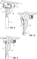
- FIGS 8-10 illustrates a pressure-sensitive connection for use in the fifth preferred aspect of the invention.
- the pressure-sensitive connection 7 is mounted on a baseplate 8 which is secured to the float.
- the connection comprises a pressure activated cylinder 71, a latch bar 72 and a hinge pin 73.
- the tensile member 21 of the tether is terminated with an eye and a pin.
- the latch bar 72 supports both the eye and the pin, and allows both to pull free when the pressure piston collapses the air chamber.
Landscapes
- Engineering & Computer Science (AREA)
- Chemical & Material Sciences (AREA)
- Combustion & Propulsion (AREA)
- Mechanical Engineering (AREA)
- Ocean & Marine Engineering (AREA)
- General Engineering & Computer Science (AREA)
- Other Liquid Machine Or Engine Such As Wave Power Use (AREA)
- Laying Of Electric Cables Or Lines Outside (AREA)
- Testing Or Calibration Of Command Recording Devices (AREA)
Priority Applications (1)
| Application Number | Priority Date | Filing Date | Title |
|---|---|---|---|
| EP18209974.7A EP3514050B1 (en) | 2007-03-02 | 2008-02-29 | Wave power |
Applications Claiming Priority (2)
| Application Number | Priority Date | Filing Date | Title |
|---|---|---|---|
| US90464707P | 2007-03-02 | 2007-03-02 | |
| PCT/US2008/002743 WO2008109002A2 (en) | 2007-03-02 | 2008-02-29 | Wave power |
Related Child Applications (1)
| Application Number | Title | Priority Date | Filing Date |
|---|---|---|---|
| EP18209974.7A Division EP3514050B1 (en) | 2007-03-02 | 2008-02-29 | Wave power |
Publications (3)
| Publication Number | Publication Date |
|---|---|
| EP2125501A2 EP2125501A2 (en) | 2009-12-02 |
| EP2125501A4 EP2125501A4 (en) | 2013-02-13 |
| EP2125501B1 true EP2125501B1 (en) | 2018-12-05 |
Family
ID=39738970
Family Applications (2)
| Application Number | Title | Priority Date | Filing Date |
|---|---|---|---|
| EP08726305.9A Active EP2125501B1 (en) | 2007-03-02 | 2008-02-29 | Wave power |
| EP18209974.7A Active EP3514050B1 (en) | 2007-03-02 | 2008-02-29 | Wave power |
Family Applications After (1)
| Application Number | Title | Priority Date | Filing Date |
|---|---|---|---|
| EP18209974.7A Active EP3514050B1 (en) | 2007-03-02 | 2008-02-29 | Wave power |
Country Status (7)
| Country | Link |
|---|---|
| US (5) | US8668534B2 (enExample) |
| EP (2) | EP2125501B1 (enExample) |
| JP (1) | JP5248530B2 (enExample) |
| CN (1) | CN101622173B (enExample) |
| AU (1) | AU2008223557B2 (enExample) |
| CA (1) | CA2679565C (enExample) |
| WO (1) | WO2008109002A2 (enExample) |
Families Citing this family (22)
| Publication number | Priority date | Publication date | Assignee | Title |
|---|---|---|---|---|
| EP2821339B1 (en) | 2006-01-20 | 2023-11-08 | Liquid Robotics, Inc. | Wave power |
| US8668534B2 (en) | 2007-03-02 | 2014-03-11 | Liquid Robotics, Inc | Wave power |
| US9524646B2 (en) | 2011-03-17 | 2016-12-20 | Liquid Robotics, Inc. | Navigation of a fleet of autonomous vessels in current and wind |
| MY166904A (en) | 2011-03-17 | 2018-07-24 | Liquid Robotics Inc | Wave-powered devices configured for nesting |
| AU2012228951B2 (en) | 2011-03-17 | 2016-05-05 | Liquid Robotics, Inc. | Wave-powered device with one or more tethers having one or more rigid sections |
| WO2012126017A2 (en) | 2011-03-17 | 2012-09-20 | Liquid Robotics Inc. | Autonomous wave-powered substance distribution vessels for fertilizing plankton, feeding fish, and sequestering carbon from the atmosphere |
| MY164096A (en) | 2011-06-28 | 2017-11-30 | Liquid Robotics Inc | Watercraft that harvest both locomotive thrust and electrical power from wave motion |
| US9533740B2 (en) | 2013-03-15 | 2017-01-03 | Liquid Robotics, Inc. | Adaptable modular power system (AMPS) |
| EP2969657B1 (en) | 2013-03-15 | 2025-01-01 | Liquid Robotics, Inc. | Adaptable modular power system (amps) with dedicated connector |
| CN103587654A (zh) * | 2013-03-18 | 2014-02-19 | 上海海洋大学 | 海洋波浪能自供电循环探测生态浮标 |
| US11978571B2 (en) | 2013-05-03 | 2024-05-07 | Christopher M. Rey | Method of coiling a superconducting cable with clocking feature |
| US11133120B2 (en) * | 2014-04-30 | 2021-09-28 | Christopher Mark Rey | Superconductor cable or superconductor cable-in-conduit-conductor with clocking feature |
| US10309367B2 (en) * | 2014-06-04 | 2019-06-04 | Mitchell Fait | Systems and methods for obtaining energy from surface waves |
| US9791862B1 (en) | 2016-04-25 | 2017-10-17 | Thayermahan, Inc. | Systems and method for unmanned undersea sensor position, orientation, and depth keeping |
| CN105775069A (zh) * | 2016-04-29 | 2016-07-20 | 武汉理工大学 | 能利用波浪能发电的航标 |
| JP6966545B2 (ja) * | 2016-07-28 | 2021-11-17 | バーデックス コーポレイション | 深度調節可能パラベーンを備えた波エネルギ変換器 |
| US9778388B1 (en) | 2016-12-22 | 2017-10-03 | Thayermahan, Inc. | Systems and methods for autonomous towing of an underwater sensor array |
| CN112635115B (zh) * | 2020-12-08 | 2022-10-11 | 安徽华津电缆集团有限公司 | 一种海上漂浮风力发电电缆 |
| WO2022261109A1 (en) | 2021-06-10 | 2022-12-15 | Bardex Corporation | Parametric wave energy, subsea power generation |
| EP4387816A4 (en) * | 2021-08-17 | 2025-04-30 | Roam Robotics Inc. | Maritime applications for a mobile robot |
| CN116660092B (zh) * | 2023-05-31 | 2024-04-16 | 中国地质科学院岩溶地质研究所 | 一种水-气界面co2通量的测算系统和方法 |
| CN120462603B (zh) * | 2025-06-09 | 2025-12-23 | 兴化市方圆消防器材有限公司 | 一种水下救援设备 |
Family Cites Families (134)
| Publication number | Priority date | Publication date | Assignee | Title |
|---|---|---|---|---|
| US1316267A (en) * | 1919-09-16 | Metallurgical furnace | ||
| US1315267A (en) * | 1919-09-09 | Morkis columbus white | ||
| US986627A (en) * | 1910-06-15 | 1911-03-14 | Herbert E Fisher | Ship's wave-motor. |
| US1067113A (en) * | 1912-10-09 | 1913-07-08 | Friedrich Heyn | Buoy for streams and currents. |
| US2170914A (en) * | 1935-01-14 | 1939-08-29 | Rummler Rudow | Rigging |
| US2668512A (en) * | 1943-04-15 | 1954-02-09 | Harold W Klas | Faired towing means for antitorpedo devices |
| US2520804A (en) | 1947-12-24 | 1950-08-29 | Oliver A Hollar | Watercraft with pivoted flappers |
| US2891501A (en) * | 1953-05-06 | 1959-06-23 | Roy L Rather | Articulated tow chain |
| US2868504A (en) | 1955-03-02 | 1959-01-13 | Manning Maxwell & Moore Inc | Non-fouling winch |
| FR1159028A (fr) | 1956-10-08 | 1958-06-23 | Procédé et dispositif pour le transport de fret, en particulier de charges payantes liquides ou pulvérulentes, par voie d'eau et plus spécialement par mer | |
| US3012757A (en) | 1957-06-21 | 1961-12-12 | Farwell Ozmun Kirk & Co | Boat hoist |
| BE570555A (fr) | 1958-08-22 | 1958-09-15 | F. Leleu | Propulseur marin employant la force vive des vagues et le calme relatif des couches d'eau plus profondes |
| US3132322A (en) * | 1959-02-09 | 1964-05-05 | Electronique Appliquee | Radiosonic buoys |
| US3043133A (en) | 1959-03-23 | 1962-07-10 | Lorenzo A Richards | Gace attachment and air removal arrangement for soil-moisture tensiometers |
| US3205570A (en) | 1964-01-20 | 1965-09-14 | Louis H Morin | Method of casting and trimming sliders in multiple, utilizing unitary bifurcated cores |
| US3297814A (en) * | 1964-11-02 | 1967-01-10 | Northern Electric Co | Semi-conducting sheath selfsupporting cable |
| US3312186A (en) * | 1965-08-27 | 1967-04-04 | Litsheim Olav | Ship propelling means |
| US3341871A (en) | 1965-10-04 | 1967-09-19 | Universal Oil Prod Co | Flotation gear for the recovery of a submerged craft |
| US3352274A (en) * | 1966-03-03 | 1967-11-14 | Dale E Clakins | High speed faired towing cable |
| US3453981A (en) | 1967-04-24 | 1969-07-08 | Joseph A Gause | Water-borne vessel comprising propulsion system incorporating flexible fin propulsion members |
| US3443020A (en) * | 1967-11-22 | 1969-05-06 | Uniroyal Inc | Faired cable |
| US3508516A (en) | 1968-05-13 | 1970-04-28 | Lloyd B Root | Wave propelled boat |
| US3613627A (en) * | 1970-06-15 | 1971-10-19 | Boeing Co | High speed faired towing cable |
| DE2149592A1 (de) * | 1971-10-05 | 1973-04-12 | Ver Flugtechnische Werke | Stroemungsguenstige verkleidung, insbesondere fuer unterwasserkabel |
| JPS4883584A (enExample) * | 1972-02-14 | 1973-11-07 | ||
| US3760441A (en) * | 1972-12-06 | 1973-09-25 | P Handelman | Position indicating temporary buoy consisting of a telescopic collapsible pole |
| US3845733A (en) | 1973-01-02 | 1974-11-05 | R Jackman | Boat propulsion means |
| US3860900A (en) * | 1973-02-21 | 1975-01-14 | Western Electric Co | Method of monitoring the position of towed underwater apparatus |
| US3828380A (en) * | 1973-03-08 | 1974-08-13 | Global Marine Inc | Fixed freeboard spar buoy |
| US3928967A (en) | 1973-11-15 | 1975-12-30 | Stephen Hugh Salter | Apparatus and method for extracting wave energy |
| US3872819A (en) | 1974-02-19 | 1975-03-25 | Us Navy | Wave-actuated horizontal array stretcher |
| FR2264711B1 (enExample) * | 1974-03-19 | 1976-12-17 | France Etat | |
| US3889045A (en) * | 1974-10-07 | 1975-06-10 | John Logsdon | Securing of service lines in hollow boat masts |
| US3978813A (en) * | 1976-01-09 | 1976-09-07 | The United States Of America As Represented By The Secretary Of The Navy | Propeller-driven hydrophone array tensioning device |
| GB1571790A (en) * | 1976-01-20 | 1980-07-16 | Energy Secretary Of State For | Apparatus for extracting powers waves on water |
| GB1601743A (en) * | 1977-02-21 | 1981-11-04 | Mariani G | Floating apparatus for marking the position of a body fallen in water |
| NO140231C (no) * | 1977-11-11 | 1979-07-25 | Einar Jakobsen | Boelgemotor for fremdrift av baater |
| JPS5945557B2 (ja) | 1978-10-11 | 1984-11-07 | 防衛庁技術研究本部長 | 被曳航体 |
| NO143308C (no) | 1979-04-04 | 1981-01-14 | Einar Jakobsen | Boelgemotor, saerlig for fremdrift av baater. |
| SU825736A1 (ru) * | 1979-04-06 | 1981-04-30 | Ivanovsk Ni Ex K Mashino | Способ раскручивания жгута текстильного полотна |
| US4383725A (en) * | 1979-06-14 | 1983-05-17 | Virginia Patent Development Corp. | Cable assembly having shielded conductor |
| US4350110A (en) * | 1980-12-29 | 1982-09-21 | The United States Of America As Represented By The Secretary Of The Navy | Integrated faired towline with integral locking feature |
| US4389843A (en) | 1981-03-27 | 1983-06-28 | John Lamberti | Water wave energy transducer |
| US4673363A (en) * | 1983-06-15 | 1987-06-16 | Sippican Ocean Systems, Inc. | Marine measurement device |
| US4462211A (en) | 1983-07-08 | 1984-07-31 | Linderfelt Hal R | Apparatus for harvesting wave energy |
| US4726314A (en) * | 1983-07-21 | 1988-02-23 | Shell Oil Company | Faired umbilical cable |
| CA1250490A (en) * | 1983-07-21 | 1989-02-28 | Ray R. Ayers | Faired umbilical cable |
| JPS6157488A (ja) | 1984-08-28 | 1986-03-24 | Minoru Yanoda | 水中グライダ− |
| JPS61146498A (ja) | 1984-12-18 | 1986-07-04 | 横浜ゴム株式会社 | 切断装置に於ける自動サイズ替え方法 |
| US4638588A (en) * | 1985-01-07 | 1987-01-27 | Abadie Carole R | Fish attracting device |
| JPS61146498U (enExample) | 1985-03-02 | 1986-09-09 | ||
| US4598547A (en) * | 1985-06-03 | 1986-07-08 | Michael Danihel | Kinetic energy transducing system |
| US4842560A (en) | 1985-09-30 | 1989-06-27 | Lee Choong G | Wave powered propulsion system for watercraft |
| US4754157A (en) * | 1985-10-01 | 1988-06-28 | Windle Tom J | Float type wave energy extraction apparatus and method |
| US4610212A (en) * | 1985-10-11 | 1986-09-09 | Petrovich Enrique G | Fast self righting catamaran |
| US4684359A (en) * | 1985-10-18 | 1987-08-04 | Mobil Oil Corporation | Movable clamp orienter for draw tape |
| GR870102B (en) | 1986-01-24 | 1987-05-28 | Helmsville Pty Ltd | Wave energy devices |
| US4684350A (en) | 1986-07-31 | 1987-08-04 | Delima Daniel D | Wave-propelled marine vessel |
| US4763126A (en) * | 1986-11-04 | 1988-08-09 | Ira Jawetz | Mooring location system |
| JPS63149289A (ja) | 1986-12-13 | 1988-06-22 | Takashi Harada | 船舶推進装置 |
| US4968273A (en) | 1987-06-30 | 1990-11-06 | Adam Momot | Water-borne vessel |
| JPS6450199A (en) | 1987-08-20 | 1989-02-27 | Nec Corp | Alarm information collecting device |
| US4896620A (en) * | 1989-02-01 | 1990-01-30 | Jones Harry E | Marine buoy |
| US5084630A (en) | 1989-03-24 | 1992-01-28 | Hossein Azimi | Wave powered apparatus for generating electric power |
| US4981453A (en) * | 1989-03-31 | 1991-01-01 | Litton Systems, Inc. | Emergency transmitter buoy and bracket assembly |
| US5050519A (en) * | 1989-04-24 | 1991-09-24 | Architectural Control Systems, Inc. | Boat trolling motor control |
| FR2669886A1 (fr) | 1990-11-30 | 1992-06-05 | Kneider Francois | Moteur de navigation a l'energie des vagues. |
| WO1994010029A1 (en) | 1992-10-29 | 1994-05-11 | David John Joseph Dipnall | A device for extracting energy from moving water particles |
| TW334180U (en) | 1993-04-22 | 1998-06-11 | Whitaker Corp | High density connector |
| US5501899A (en) * | 1994-05-20 | 1996-03-26 | Larkin; William J. | Static eliminator and method |
| US5552497A (en) | 1994-12-29 | 1996-09-03 | Basf Corporation | Method of preparing carbamate-functional polymer |
| US5577942A (en) * | 1995-07-28 | 1996-11-26 | The United States Of America As Represented By The Secretary Of The Navy | Station keeping buoy system |
| US5675116A (en) | 1995-10-11 | 1997-10-07 | The United States Of America As Represented By The Secretary Of The Navy | Unmanned undersea vehicle including keel-mounted payload deployment arrangement with payload compartment flooding arrangement to maintain axi-symmetrical mass distribution |
| US5678504A (en) * | 1996-06-03 | 1997-10-21 | The United States Of America As Represented By The Secretary Of The Navy | Negative lift device for tow cable fairing |
| US6194815B1 (en) * | 1996-10-25 | 2001-02-27 | Ocean Power Technology, Inc. | Piezoelectric rotary electrical energy generator |
| US6200530B1 (en) * | 2000-03-09 | 2001-03-13 | Michael Markels, Jr. | Method of sequestering carbon dioxide with spiral fertilization |
| WO1998039205A1 (en) * | 1997-03-06 | 1998-09-11 | Vladimir Alexeevich Arkhipov | Undulating propeller using the energy generated by pitching of the vessel |
| DE69814847T2 (de) | 1997-04-16 | 2004-01-22 | Carnegie Mellon University | Agrar-erntemaschine mit roboter-kontrolle |
| US5902163A (en) * | 1997-05-09 | 1999-05-11 | Automatic Power, Inc. | Debris shedding buoy |
| US6285807B1 (en) * | 1998-11-16 | 2001-09-04 | Trustees Of Tufts College | Fiber optic sensor for long-term analyte measurements in fluids |
| US6099368A (en) * | 1999-06-07 | 2000-08-08 | Vladislav V. Gorshkov | Rocking ship propulsion and the rocking propelled ship |
| CN1132757C (zh) | 1999-07-17 | 2003-12-31 | 周德群 | 利用波浪能推进的船舶及一种稳定的水上漂浮建筑 |
| US20030174206A1 (en) * | 1999-12-03 | 2003-09-18 | Axial Technologies, Inc. | Underwater camera system |
| AUPQ453299A0 (en) | 1999-12-08 | 2000-01-06 | Advanced Marine Technologies Pty Ltd | A system for fishing |
| US6260501B1 (en) * | 2000-03-17 | 2001-07-17 | Arthur Patrick Agnew | Submersible apparatus for transporting compressed gas |
| US6768216B1 (en) * | 2000-05-26 | 2004-07-27 | Ocean Power Technologies, Inc. | Wave energy converters utilizing pressure differences |
| TW547434U (en) | 2000-06-15 | 2003-08-11 | Lung-Pin Huang | Wave-powered boat |
| FR2813644B1 (fr) * | 2000-09-06 | 2003-01-24 | Skf France | Dispositif de palier a roulement instrumente, notamment pour volant de commande |
| DE10141805A1 (de) | 2000-09-23 | 2002-05-02 | Martin Krais | Fahrzeugsteuereinrichtung von Land-, Wasser- oder Luftfahrzeugen mit Geschwindigkeits- und Wegstreckenbestimmung |
| US6561856B1 (en) * | 2001-02-07 | 2003-05-13 | Vladislav Vasilyevich Gorshkov | Power floating production and ship propulsion supported by gyroscope and energized by seas |
| US6980228B1 (en) * | 2001-03-29 | 2005-12-27 | Bellsouth Intellectual Property Corporation | Monitoring buoy system |
| US6581537B2 (en) | 2001-06-04 | 2003-06-24 | The Penn State Research Foundation | Propulsion of underwater vehicles using differential and vectored thrust |
| US6853937B2 (en) * | 2001-07-06 | 2005-02-08 | Tokyo University Of Agriculture And Technology Tlo Co., Ltd. | Soil characteristics survey device and soil characteristics survey method |
| US6756695B2 (en) | 2001-08-09 | 2004-06-29 | Aerovironment Inc. | Method of and apparatus for wave energy conversion using a float with excess buoyancy |
| US20030220027A1 (en) * | 2002-05-17 | 2003-11-27 | Gorshkov Vladislav Vasilyevich | Wave powered cyclic anchoring itinerant ship propulsion system |
| NL1020804C2 (nl) | 2002-06-06 | 2003-12-09 | Lely Entpr Ag | Werkwijze en systeem voor het uitvoeren van ten minste twee landbouwbewerkingen op een landbouwperceel. |
| US6665189B1 (en) | 2002-07-18 | 2003-12-16 | Rockwell Collins, Inc. | Modular electronics system package |
| US20040102107A1 (en) | 2002-11-22 | 2004-05-27 | Gorshkov Vladislav Vasilyevich | Wave powered propulsion systems for submarines and quasi-dipped watercrafts |
| DE10300599A1 (de) | 2003-01-10 | 2004-07-22 | Jörg Dr. Sommer | Mehrrumpfiges Schiff mit beweglichen Schwimmkörpern als Wellenkraftwerk |
| NZ545187A (en) * | 2003-07-31 | 2007-11-30 | Solar Sailor Pty Ltd | Unmanned ocean vehicle |
| US6814633B1 (en) * | 2003-08-08 | 2004-11-09 | Lung-Pin Huang | Wave powered vessel |
| CN2689229Y (zh) * | 2003-09-01 | 2005-03-30 | 国家海洋技术中心 | 极区海洋环境自动监测浮标 |
| US7854108B2 (en) * | 2003-12-12 | 2010-12-21 | Vision Robotics Corporation | Agricultural robot system and method |
| CN1715136A (zh) | 2004-07-01 | 2006-01-04 | 梅正新 | 利用船舶摇滚的力量以推动船舶前进的装置 |
| WO2007033384A2 (en) * | 2005-09-16 | 2007-03-22 | Bae Systems Land & Armaments L.P. | Launch and recovery system |
| US20140263851A1 (en) | 2013-03-14 | 2014-09-18 | Liquid Robotics, Inc. | Water Vehicles |
| US8944866B2 (en) | 2011-09-15 | 2015-02-03 | Liquid Robotics, Inc. | Wave-powered endurance extension module for unmanned underwater vehicles |
| EP2821339B1 (en) * | 2006-01-20 | 2023-11-08 | Liquid Robotics, Inc. | Wave power |
| US7371136B2 (en) * | 2006-01-20 | 2008-05-13 | Liquid Robotics Inc. | Wave power |
| FR2904287B1 (fr) | 2006-07-26 | 2008-10-24 | Ifremer | Appareil de recuperation d'un engin sous-marin ou marin |
| US7472866B2 (en) | 2006-11-15 | 2009-01-06 | The United States Of America As Represented By The Secretary Of The Navy | Deployment system and method for subsurface launched unmanned aerial vehicle |
| US8668534B2 (en) | 2007-03-02 | 2014-03-11 | Liquid Robotics, Inc | Wave power |
| WO2008153729A1 (en) * | 2007-05-23 | 2008-12-18 | Rocona, Inc. | Autonomous agriculture platform guidance system |
| US8448592B2 (en) * | 2007-10-30 | 2013-05-28 | Ocean Server Technology, Inc. | External rescue and recovery devices and methods for underwater vehicles |
| USD578463S1 (en) * | 2007-11-01 | 2008-10-14 | Vehicle Control Technologies, Inc. | Underwater vehicle |
| DE102007053037A1 (de) | 2007-11-07 | 2009-05-14 | Robert Bosch Gmbh | Wasserfahrzeug sowie Verwendung von Wandlermitteln |
| US7836633B2 (en) * | 2008-01-31 | 2010-11-23 | Brian And Cynthia Wilcox Trust | Method and apparatus for robotic ocean farming for food and energy |
| US8587150B2 (en) | 2008-02-28 | 2013-11-19 | Deeya Energy, Inc. | Method and modular system for charging a battery |
| FR2931792B1 (fr) | 2008-06-03 | 2010-11-12 | Thales Sa | Systeme pour la mise a l'eau et la recuperation automatiques d'un drone sous-marin |
| GB2461792A (en) | 2008-07-14 | 2010-01-20 | Marine Power Systems Ltd | Wave generator with optional floating configuration |
| UY31395A1 (es) * | 2008-10-15 | 2009-01-05 | Martin Eugenio Corradini | Sistema de generación de energía para embarcaciones y submarinos por medio de turbinas hidroeléctricas |
| DE202008013757U1 (de) | 2008-11-03 | 2010-03-25 | FILTEC GmbH Filtertechnologie für die Elektronikindustrie | Hybrid-Steckverbinder für Daten- und Powerleitungen |
| US8427002B2 (en) | 2009-02-02 | 2013-04-23 | Inscope Energy, Llc | System configured to control and power a vehicle or vessel |
| US8437879B2 (en) * | 2009-04-21 | 2013-05-07 | Deere & Company | System and method for providing prescribed resources to plants |
| US8113860B2 (en) | 2009-09-04 | 2012-02-14 | Graeme Richard Sandwith | High power multi-pin electrical connector |
| US8205570B1 (en) * | 2010-02-01 | 2012-06-26 | Vehicle Control Technologies, Inc. | Autonomous unmanned underwater vehicle with buoyancy engine |
| US20120029718A1 (en) * | 2010-05-21 | 2012-02-02 | Davis Edward L | Systems and methods for generating and utilizing electrical signatures for electrical and electronic equipment |
| US8418705B2 (en) * | 2010-07-30 | 2013-04-16 | Toyota Motor Engineering & Manufacturing North America, Inc. | Robotic cane devices |
| US9013952B2 (en) | 2010-09-17 | 2015-04-21 | Westerngeco L.L.C. | Marine seismic survey systems and methods using autonomously or remotely operated vehicles |
| WO2012126017A2 (en) | 2011-03-17 | 2012-09-20 | Liquid Robotics Inc. | Autonomous wave-powered substance distribution vessels for fertilizing plankton, feeding fish, and sequestering carbon from the atmosphere |
| AU2012228951B2 (en) * | 2011-03-17 | 2016-05-05 | Liquid Robotics, Inc. | Wave-powered device with one or more tethers having one or more rigid sections |
| MY164096A (en) | 2011-06-28 | 2017-11-30 | Liquid Robotics Inc | Watercraft that harvest both locomotive thrust and electrical power from wave motion |
| US20140283726A1 (en) | 2013-03-15 | 2014-09-25 | Liquid Robotics, Inc. | Modular Payload Boxes and Autonomous Water Vehicle Configured to Accept Same |
| US9533740B2 (en) | 2013-03-15 | 2017-01-03 | Liquid Robotics, Inc. | Adaptable modular power system (AMPS) |
-
2008
- 2008-02-29 US US12/449,753 patent/US8668534B2/en active Active
- 2008-02-29 EP EP08726305.9A patent/EP2125501B1/en active Active
- 2008-02-29 AU AU2008223557A patent/AU2008223557B2/en active Active
- 2008-02-29 CA CA2679565A patent/CA2679565C/en active Active
- 2008-02-29 EP EP18209974.7A patent/EP3514050B1/en active Active
- 2008-02-29 JP JP2009551747A patent/JP5248530B2/ja active Active
- 2008-02-29 CN CN2008800069033A patent/CN101622173B/zh active Active
- 2008-02-29 WO PCT/US2008/002743 patent/WO2008109002A2/en not_active Ceased
-
2014
- 2014-02-04 US US14/172,860 patent/US9789944B2/en active Active
-
2017
- 2017-10-16 US US15/785,246 patent/US10315746B2/en active Active
-
2019
- 2019-06-10 US US16/436,759 patent/US11027810B2/en active Active
-
2021
- 2021-05-17 US US17/322,542 patent/US11685494B2/en active Active
Non-Patent Citations (1)
| Title |
|---|
| None * |
Also Published As
| Publication number | Publication date |
|---|---|
| WO2008109002A2 (en) | 2008-09-12 |
| JP5248530B2 (ja) | 2013-07-31 |
| CN101622173A (zh) | 2010-01-06 |
| EP2125501A4 (en) | 2013-02-13 |
| US8668534B2 (en) | 2014-03-11 |
| US11685494B2 (en) | 2023-06-27 |
| EP3514050A1 (en) | 2019-07-24 |
| AU2008223557A1 (en) | 2008-09-12 |
| US20100190394A1 (en) | 2010-07-29 |
| US20190359305A1 (en) | 2019-11-28 |
| JP2010520103A (ja) | 2010-06-10 |
| US9789944B2 (en) | 2017-10-17 |
| AU2008223557B2 (en) | 2013-10-24 |
| WO2008109002A3 (en) | 2008-11-13 |
| US11027810B2 (en) | 2021-06-08 |
| EP2125501A2 (en) | 2009-12-02 |
| CA2679565A1 (en) | 2008-09-12 |
| CN101622173B (zh) | 2013-03-27 |
| US20210269135A1 (en) | 2021-09-02 |
| EP3514050B1 (en) | 2020-12-09 |
| US20140335747A1 (en) | 2014-11-13 |
| US20180134359A1 (en) | 2018-05-17 |
| US10315746B2 (en) | 2019-06-11 |
| CA2679565C (en) | 2015-06-30 |
Similar Documents
| Publication | Publication Date | Title |
|---|---|---|
| US11685494B2 (en) | Method and apparatus for untwisting a tether of a water powered vehicle | |
| US9822757B2 (en) | Underwater tethered telemetry platform | |
| US9828068B2 (en) | Mechanical tether system for a submersible vehicle | |
| US9899127B2 (en) | Tethers for airborne wind turbines | |
| JP2010519518A (ja) | 自力推進地震探査ストリーマシステム | |
| US10272979B2 (en) | System and method for subsea propulsion and energy harvesting using current shear | |
| WO2008024646A2 (en) | A mooring line for an oceanographic buoy system | |
| WO2018118199A1 (en) | Offshore wind kite with separate perch and tether platforms | |
| CN115479588B (zh) | 一种小型走航式连续温盐剖面观测系统 | |
| US9947434B2 (en) | Tethers for airborne wind turbines using electrical conductor bundles | |
| JP5216150B1 (ja) | 水中観測装置 | |
| GB1591356A (en) | Buoyancy device and method | |
| CN116626834B (zh) | 用于海底光缆布设的布缆系统及布缆方法 | |
| CN114009386B (zh) | 深海远洋养殖网箱智能锚固系统、智能锚固方法 | |
| CN117968817A (zh) | 一种深海海底快速布放阵列系统及其布放方法 | |
| Trask et al. | Oceanographic Institution, Woods Hole, MA, USA |
Legal Events
| Date | Code | Title | Description |
|---|---|---|---|
| PUAI | Public reference made under article 153(3) epc to a published international application that has entered the european phase |
Free format text: ORIGINAL CODE: 0009012 |
|
| 17P | Request for examination filed |
Effective date: 20090812 |
|
| AK | Designated contracting states |
Kind code of ref document: A2 Designated state(s): AT BE BG CH CY CZ DE DK EE ES FI FR GB GR HR HU IE IS IT LI LT LU LV MC MT NL NO PL PT RO SE SI SK TR |
|
| RAP1 | Party data changed (applicant data changed or rights of an application transferred) |
Owner name: LIQUID ROBOTICS REINCORPORATION SUB, INCORPORATED |
|
| RAP1 | Party data changed (applicant data changed or rights of an application transferred) |
Owner name: LIQUID ROBOTICS, INC. |
|
| DAX | Request for extension of the european patent (deleted) | ||
| A4 | Supplementary search report drawn up and despatched |
Effective date: 20130115 |
|
| RIC1 | Information provided on ipc code assigned before grant |
Ipc: B63H 19/02 20060101ALI20130109BHEP Ipc: B63B 21/66 20060101AFI20130109BHEP |
|
| STAA | Information on the status of an ep patent application or granted ep patent |
Free format text: STATUS: EXAMINATION IS IN PROGRESS |
|
| 17Q | First examination report despatched |
Effective date: 20171027 |
|
| GRAP | Despatch of communication of intention to grant a patent |
Free format text: ORIGINAL CODE: EPIDOSNIGR1 |
|
| STAA | Information on the status of an ep patent application or granted ep patent |
Free format text: STATUS: GRANT OF PATENT IS INTENDED |
|
| INTG | Intention to grant announced |
Effective date: 20180614 |
|
| GRAS | Grant fee paid |
Free format text: ORIGINAL CODE: EPIDOSNIGR3 |
|
| GRAJ | Information related to disapproval of communication of intention to grant by the applicant or resumption of examination proceedings by the epo deleted |
Free format text: ORIGINAL CODE: EPIDOSDIGR1 |
|
| GRAL | Information related to payment of fee for publishing/printing deleted |
Free format text: ORIGINAL CODE: EPIDOSDIGR3 |
|
| STAA | Information on the status of an ep patent application or granted ep patent |
Free format text: STATUS: EXAMINATION IS IN PROGRESS |
|
| INTC | Intention to grant announced (deleted) | ||
| GRAR | Information related to intention to grant a patent recorded |
Free format text: ORIGINAL CODE: EPIDOSNIGR71 |
|
| STAA | Information on the status of an ep patent application or granted ep patent |
Free format text: STATUS: GRANT OF PATENT IS INTENDED |
|
| GRAA | (expected) grant |
Free format text: ORIGINAL CODE: 0009210 |
|
| GRAA | (expected) grant |
Free format text: ORIGINAL CODE: 0009210 |
|
| STAA | Information on the status of an ep patent application or granted ep patent |
Free format text: STATUS: THE PATENT HAS BEEN GRANTED |
|
| AK | Designated contracting states |
Kind code of ref document: B1 Designated state(s): AT BE BG CH CY CZ DE DK EE ES FI FR GB GR HR HU IE IS IT LI LT LU LV MC MT NL NO PL PT RO SE SI SK TR |
|
| INTG | Intention to grant announced |
Effective date: 20181030 |
|
| REG | Reference to a national code |
Ref country code: GB Ref legal event code: FG4D |
|
| REG | Reference to a national code |
Ref country code: CH Ref legal event code: EP |
|
| REG | Reference to a national code |
Ref country code: AT Ref legal event code: REF Ref document number: 1072685 Country of ref document: AT Kind code of ref document: T Effective date: 20181215 |
|
| REG | Reference to a national code |
Ref country code: IE Ref legal event code: FG4D |
|
| REG | Reference to a national code |
Ref country code: DE Ref legal event code: R096 Ref document number: 602008058193 Country of ref document: DE |
|
| REG | Reference to a national code |
Ref country code: NL Ref legal event code: MP Effective date: 20181205 |
|
| REG | Reference to a national code |
Ref country code: AT Ref legal event code: MK05 Ref document number: 1072685 Country of ref document: AT Kind code of ref document: T Effective date: 20181205 |
|
| REG | Reference to a national code |
Ref country code: LT Ref legal event code: MG4D |
|
| PG25 | Lapsed in a contracting state [announced via postgrant information from national office to epo] |
Ref country code: ES Free format text: LAPSE BECAUSE OF FAILURE TO SUBMIT A TRANSLATION OF THE DESCRIPTION OR TO PAY THE FEE WITHIN THE PRESCRIBED TIME-LIMIT Effective date: 20181205 Ref country code: AT Free format text: LAPSE BECAUSE OF FAILURE TO SUBMIT A TRANSLATION OF THE DESCRIPTION OR TO PAY THE FEE WITHIN THE PRESCRIBED TIME-LIMIT Effective date: 20181205 Ref country code: HR Free format text: LAPSE BECAUSE OF FAILURE TO SUBMIT A TRANSLATION OF THE DESCRIPTION OR TO PAY THE FEE WITHIN THE PRESCRIBED TIME-LIMIT Effective date: 20181205 Ref country code: LV Free format text: LAPSE BECAUSE OF FAILURE TO SUBMIT A TRANSLATION OF THE DESCRIPTION OR TO PAY THE FEE WITHIN THE PRESCRIBED TIME-LIMIT Effective date: 20181205 Ref country code: FI Free format text: LAPSE BECAUSE OF FAILURE TO SUBMIT A TRANSLATION OF THE DESCRIPTION OR TO PAY THE FEE WITHIN THE PRESCRIBED TIME-LIMIT Effective date: 20181205 Ref country code: BG Free format text: LAPSE BECAUSE OF FAILURE TO SUBMIT A TRANSLATION OF THE DESCRIPTION OR TO PAY THE FEE WITHIN THE PRESCRIBED TIME-LIMIT Effective date: 20190305 Ref country code: NO Free format text: LAPSE BECAUSE OF FAILURE TO SUBMIT A TRANSLATION OF THE DESCRIPTION OR TO PAY THE FEE WITHIN THE PRESCRIBED TIME-LIMIT Effective date: 20190305 Ref country code: LT Free format text: LAPSE BECAUSE OF FAILURE TO SUBMIT A TRANSLATION OF THE DESCRIPTION OR TO PAY THE FEE WITHIN THE PRESCRIBED TIME-LIMIT Effective date: 20181205 |
|
| PG25 | Lapsed in a contracting state [announced via postgrant information from national office to epo] |
Ref country code: GR Free format text: LAPSE BECAUSE OF FAILURE TO SUBMIT A TRANSLATION OF THE DESCRIPTION OR TO PAY THE FEE WITHIN THE PRESCRIBED TIME-LIMIT Effective date: 20190306 Ref country code: SE Free format text: LAPSE BECAUSE OF FAILURE TO SUBMIT A TRANSLATION OF THE DESCRIPTION OR TO PAY THE FEE WITHIN THE PRESCRIBED TIME-LIMIT Effective date: 20181205 |
|
| PG25 | Lapsed in a contracting state [announced via postgrant information from national office to epo] |
Ref country code: NL Free format text: LAPSE BECAUSE OF FAILURE TO SUBMIT A TRANSLATION OF THE DESCRIPTION OR TO PAY THE FEE WITHIN THE PRESCRIBED TIME-LIMIT Effective date: 20181205 |
|
| PG25 | Lapsed in a contracting state [announced via postgrant information from national office to epo] |
Ref country code: PL Free format text: LAPSE BECAUSE OF FAILURE TO SUBMIT A TRANSLATION OF THE DESCRIPTION OR TO PAY THE FEE WITHIN THE PRESCRIBED TIME-LIMIT Effective date: 20181205 Ref country code: CZ Free format text: LAPSE BECAUSE OF FAILURE TO SUBMIT A TRANSLATION OF THE DESCRIPTION OR TO PAY THE FEE WITHIN THE PRESCRIBED TIME-LIMIT Effective date: 20181205 Ref country code: PT Free format text: LAPSE BECAUSE OF FAILURE TO SUBMIT A TRANSLATION OF THE DESCRIPTION OR TO PAY THE FEE WITHIN THE PRESCRIBED TIME-LIMIT Effective date: 20190405 Ref country code: IT Free format text: LAPSE BECAUSE OF FAILURE TO SUBMIT A TRANSLATION OF THE DESCRIPTION OR TO PAY THE FEE WITHIN THE PRESCRIBED TIME-LIMIT Effective date: 20181205 |
|
| PG25 | Lapsed in a contracting state [announced via postgrant information from national office to epo] |
Ref country code: SK Free format text: LAPSE BECAUSE OF FAILURE TO SUBMIT A TRANSLATION OF THE DESCRIPTION OR TO PAY THE FEE WITHIN THE PRESCRIBED TIME-LIMIT Effective date: 20181205 Ref country code: EE Free format text: LAPSE BECAUSE OF FAILURE TO SUBMIT A TRANSLATION OF THE DESCRIPTION OR TO PAY THE FEE WITHIN THE PRESCRIBED TIME-LIMIT Effective date: 20181205 Ref country code: IS Free format text: LAPSE BECAUSE OF FAILURE TO SUBMIT A TRANSLATION OF THE DESCRIPTION OR TO PAY THE FEE WITHIN THE PRESCRIBED TIME-LIMIT Effective date: 20190405 Ref country code: RO Free format text: LAPSE BECAUSE OF FAILURE TO SUBMIT A TRANSLATION OF THE DESCRIPTION OR TO PAY THE FEE WITHIN THE PRESCRIBED TIME-LIMIT Effective date: 20181205 |
|
| REG | Reference to a national code |
Ref country code: DE Ref legal event code: R097 Ref document number: 602008058193 Country of ref document: DE |
|
| REG | Reference to a national code |
Ref country code: CH Ref legal event code: PL |
|
| PLBE | No opposition filed within time limit |
Free format text: ORIGINAL CODE: 0009261 |
|
| STAA | Information on the status of an ep patent application or granted ep patent |
Free format text: STATUS: NO OPPOSITION FILED WITHIN TIME LIMIT |
|
| PG25 | Lapsed in a contracting state [announced via postgrant information from national office to epo] |
Ref country code: SI Free format text: LAPSE BECAUSE OF FAILURE TO SUBMIT A TRANSLATION OF THE DESCRIPTION OR TO PAY THE FEE WITHIN THE PRESCRIBED TIME-LIMIT Effective date: 20181205 Ref country code: MC Free format text: LAPSE BECAUSE OF FAILURE TO SUBMIT A TRANSLATION OF THE DESCRIPTION OR TO PAY THE FEE WITHIN THE PRESCRIBED TIME-LIMIT Effective date: 20181205 Ref country code: DK Free format text: LAPSE BECAUSE OF FAILURE TO SUBMIT A TRANSLATION OF THE DESCRIPTION OR TO PAY THE FEE WITHIN THE PRESCRIBED TIME-LIMIT Effective date: 20181205 Ref country code: LU Free format text: LAPSE BECAUSE OF NON-PAYMENT OF DUE FEES Effective date: 20190228 |
|
| 26N | No opposition filed |
Effective date: 20190906 |
|
| REG | Reference to a national code |
Ref country code: BE Ref legal event code: MM Effective date: 20190228 |
|
| REG | Reference to a national code |
Ref country code: IE Ref legal event code: MM4A |
|
| PG25 | Lapsed in a contracting state [announced via postgrant information from national office to epo] |
Ref country code: CH Free format text: LAPSE BECAUSE OF NON-PAYMENT OF DUE FEES Effective date: 20190228 Ref country code: LI Free format text: LAPSE BECAUSE OF NON-PAYMENT OF DUE FEES Effective date: 20190228 |
|
| PG25 | Lapsed in a contracting state [announced via postgrant information from national office to epo] |
Ref country code: IE Free format text: LAPSE BECAUSE OF NON-PAYMENT OF DUE FEES Effective date: 20190228 |
|
| PG25 | Lapsed in a contracting state [announced via postgrant information from national office to epo] |
Ref country code: BE Free format text: LAPSE BECAUSE OF NON-PAYMENT OF DUE FEES Effective date: 20190228 |
|
| PG25 | Lapsed in a contracting state [announced via postgrant information from national office to epo] |
Ref country code: TR Free format text: LAPSE BECAUSE OF FAILURE TO SUBMIT A TRANSLATION OF THE DESCRIPTION OR TO PAY THE FEE WITHIN THE PRESCRIBED TIME-LIMIT Effective date: 20181205 |
|
| PG25 | Lapsed in a contracting state [announced via postgrant information from national office to epo] |
Ref country code: MT Free format text: LAPSE BECAUSE OF NON-PAYMENT OF DUE FEES Effective date: 20190228 |
|
| PG25 | Lapsed in a contracting state [announced via postgrant information from national office to epo] |
Ref country code: CY Free format text: LAPSE BECAUSE OF FAILURE TO SUBMIT A TRANSLATION OF THE DESCRIPTION OR TO PAY THE FEE WITHIN THE PRESCRIBED TIME-LIMIT Effective date: 20181205 |
|
| PG25 | Lapsed in a contracting state [announced via postgrant information from national office to epo] |
Ref country code: HU Free format text: LAPSE BECAUSE OF FAILURE TO SUBMIT A TRANSLATION OF THE DESCRIPTION OR TO PAY THE FEE WITHIN THE PRESCRIBED TIME-LIMIT; INVALID AB INITIO Effective date: 20080229 |
|
| P01 | Opt-out of the competence of the unified patent court (upc) registered |
Effective date: 20230516 |
|
| PGFP | Annual fee paid to national office [announced via postgrant information from national office to epo] |
Ref country code: DE Payment date: 20250227 Year of fee payment: 18 |
|
| PGFP | Annual fee paid to national office [announced via postgrant information from national office to epo] |
Ref country code: FR Payment date: 20250225 Year of fee payment: 18 |
|
| PGFP | Annual fee paid to national office [announced via postgrant information from national office to epo] |
Ref country code: GB Payment date: 20250227 Year of fee payment: 18 |