EP2125153B1 - Filteranordnung zum reinigen von partikelbelasteten prozessgasen und verfahren zum reinigen von filtereinheiten einer solchen filteranordnung - Google Patents
Filteranordnung zum reinigen von partikelbelasteten prozessgasen und verfahren zum reinigen von filtereinheiten einer solchen filteranordnung Download PDFInfo
- Publication number
- EP2125153B1 EP2125153B1 EP08801803A EP08801803A EP2125153B1 EP 2125153 B1 EP2125153 B1 EP 2125153B1 EP 08801803 A EP08801803 A EP 08801803A EP 08801803 A EP08801803 A EP 08801803A EP 2125153 B1 EP2125153 B1 EP 2125153B1
- Authority
- EP
- European Patent Office
- Prior art keywords
- filter
- cleaning
- filter unit
- exterior
- filters
- Prior art date
- Legal status (The legal status is an assumption and is not a legal conclusion. Google has not performed a legal analysis and makes no representation as to the accuracy of the status listed.)
- Active
Links
Images


Classifications
-
- B—PERFORMING OPERATIONS; TRANSPORTING
- B01—PHYSICAL OR CHEMICAL PROCESSES OR APPARATUS IN GENERAL
- B01D—SEPARATION
- B01D46/00—Filters or filtering processes specially modified for separating dispersed particles from gases or vapours
- B01D46/66—Regeneration of the filtering material or filter elements inside the filter
- B01D46/70—Regeneration of the filtering material or filter elements inside the filter by acting counter-currently on the filtering surface, e.g. by flushing on the non-cake side of the filter
-
- B—PERFORMING OPERATIONS; TRANSPORTING
- B01—PHYSICAL OR CHEMICAL PROCESSES OR APPARATUS IN GENERAL
- B01D—SEPARATION
- B01D46/00—Filters or filtering processes specially modified for separating dispersed particles from gases or vapours
- B01D46/24—Particle separators, e.g. dust precipitators, using rigid hollow filter bodies
- B01D46/2403—Particle separators, e.g. dust precipitators, using rigid hollow filter bodies characterised by the physical shape or structure of the filtering element
-
- B—PERFORMING OPERATIONS; TRANSPORTING
- B01—PHYSICAL OR CHEMICAL PROCESSES OR APPARATUS IN GENERAL
- B01D—SEPARATION
- B01D46/00—Filters or filtering processes specially modified for separating dispersed particles from gases or vapours
- B01D46/56—Filters or filtering processes specially modified for separating dispersed particles from gases or vapours with multiple filtering elements, characterised by their mutual disposition
- B01D46/58—Filters or filtering processes specially modified for separating dispersed particles from gases or vapours with multiple filtering elements, characterised by their mutual disposition connected in parallel
- B01D46/60—Filters or filtering processes specially modified for separating dispersed particles from gases or vapours with multiple filtering elements, characterised by their mutual disposition connected in parallel arranged concentrically or coaxially
-
- B—PERFORMING OPERATIONS; TRANSPORTING
- B01—PHYSICAL OR CHEMICAL PROCESSES OR APPARATUS IN GENERAL
- B01D—SEPARATION
- B01D46/00—Filters or filtering processes specially modified for separating dispersed particles from gases or vapours
- B01D46/66—Regeneration of the filtering material or filter elements inside the filter
- B01D46/69—Regeneration of the filtering material or filter elements inside the filter by means acting on the cake side without movement with respect to the filter elements, e.g. fixed nozzles
Definitions
- the invention relates to a filter arrangement for cleaning particles contaminated gases according to the preamble of claim 1 and to a method for cleaning at least one filter unit according to the preamble of claim 11.
- the invention relates to a filter assembly disposed above and on a process vessel in which particulate material is treated, such as by mixing, drying, granulating, pelleting and / or coating (coating) the product.
- the process may consist in that dust-fine good particles are agglomerated or granulated in the process vessel to form larger particles, or a particulate starting material is provided with a coating by means of coating (coating).
- an air-permeable bottom is generally provided in the bottom region of the process container, which has passages, in particular in the form of slots.
- Such filter units are in the WO 01/51172 A3 and in the WO 02/43835 described in which vertically oriented Filter hoses are arranged, wherein above the filter hoses, washing nozzles are provided to wet the dust air space with water.
- the disadvantage here is that a complete cleaning of the filter bags with this arrangement can not be done.
- a dedusting device which consists of a certain number of fabric tubes, which in turn each enclose another fabric tube which is closed at its upper end. Dust particles settle on the inner wall of the outer fabric hoses and on the outer wall of the inner fabric hoses.
- Another filter unit consisting of a cylindrical outer filter and a conically tapering from bottom to top internal filter is from the DE 40 29 994 C2 known.
- Gut treating process operation air contaminated with particles, such as dust from the outside through the outer filter and from the inside through the inner filter in a space between the outer and inner filters of the filter unit and an open valve to a gas outlet promoted.
- the valve For blowing off on the outside of the outer filter and the inside of the inner filter accumulated dust, the valve is closed and opened via another valve, an air passage from a gas inlet for clean gas to the space between the inner and outer filters, so that in countercurrent blowing off on the outside of the Outside and inside of the inner filter adhering particle can be done.
- This does not always allow complete cleaning on the side of the filters facing the dust-laden air, removal of filter dust that has penetrated into the clean air area is difficult to carry out. For a complete cleaning of the filter unit this must be removed and disassembled and the individual filters must then be cleaned individually. In the prior art, cleaning on site or cleaning in place (CIP) is not possible without removing the filter cartridges.
- CIP cleaning on site or cleaning in place
- the invention is therefore an object of the invention to provide a filter assembly of the type mentioned, and in particular their filter units can be completely and comprehensively cleaned in place and provide a method for performing such a cleaning.
- the object is achieved in a filter assembly of the type mentioned by the characterizing features of claim 1.
- the invention provides a method of the type mentioned above with the characterizing features of claim 11.
- the invention provides that the outer and inner filters can be moved relative to one another by releasing an annular gap, wherein in particular the inner filter can be raised relative to the outer filter or the inner filter can be lowered relative to the outer filter.
- the drive for generating the relative movement between the inner and outer filters is effected by a drive device outside the filter unit, for example via an actuating rod.
- the invention further provides a device for injecting fluid, in particular gas, into the clean-gas-side region of the filter unit and a device for shutting off the clean-room-side region of the filter unit from an outlet and by a projecting into the clean room side of the filter unit lance for spraying cleaning fluid in this area of the filter unit and by an in the clean gas side facing the outer space of the at least one filter unit, in particular in a surrounding Filterdom projecting cleaning lance for cleaning the particle-laden gas exposed sides of Filter unit by means of liquid before.
- a device for injecting fluid, in particular gas into the clean-gas-side region of the filter unit and a device for shutting off the clean-room-side region of the filter unit from an outlet and by a projecting into the clean room side of the filter unit lance for spraying cleaning fluid in this area of the filter unit and by an in the clean gas side facing the outer space of the at least one filter unit, in particular in a surrounding Filterdom projecting cleaning lance for cleaning the particle-laden gas exposed sides of Filter
- the gap in the lower region between the outer and inner filters of the at least one filter unit by lowering or raising the inner filter relative to the outer filter opened and closed by opposite movement.
- cleaning steps can be provided in such a way that cleaning gas is blown into the filter unit and against the flow direction during the cleaning operation of the same by closing a gas outlet from the cleanroom-side region of the filter unit, that areas of the filter remote from the clean gas space of the filter unit be cleaned by means of a cleaning liquid ejected from a cleaning lance and that, as already said, a drying of the at least one filter unit under opening the gap between the outer and inner filters.
- the invention provides, prior to drying, that metal filters of the filter unit are cleaned by introducing coupling liquid into the space between the outer and inner filters with the gap closed between the two filters by means of an ultrasonic source protruding into the intermediate space.
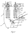
- the filter assembly 1 is arranged on a process container 2 tapering from top to bottom.
- a process container 2 for example, particulate material is treated, such as by mixing, drying, granulating, pelleting and / or coating (coating) of the goods.
- dust-fine good particles can be agglomerated into the process container to form larger particles and thus granulated or else Particulate starting material are provided by coating with a coating.
- an air-permeable bottom 2.1 is usually provided in the bottom region of the process container 2, which has passages, in particular in the form of slots. In this floor or in the cylindrical wall integrated nozzles can be arranged, which allow spraying of a coating medium.
- the filter assembly 1 has several, usually three to six filter units 3 in a housing-like filter dome 1.1.
- a filter unit 3 has an outer filter filter 3.1 and an inner filter 3.2, wherein the outer filter 3.1 is cylindrical and in the illustrated embodiment is generally cylindrical, while the inner filter 3.2 is conically formed in the rule and in the illustrated embodiment, namely tapering from bottom to top ,
- the lower edges of the outer filter 3.1 and the inner filter 3.2 are aligned with one another and are connected to one another via a closed annular region 3.4. as is the state of the art.
- the top of the inner filter 3.2 ends below the upper end of the outer filter 3.1.
- the ring-shaped intermediate space 3.5 between the outer and inner filters 3.1, 3.2, in which the clean air flows through the filter communicates with an outlet 3.6 for the clean air above the inner filter 3.2 in combination, in turn via an openable flap 3.7 with an exhaust pipe 3.8 in fluid communication stands.
- the internal filter 3.2 is connected via an actuating rod 3.3.1 with a drive 3.3.2, through which the internal filter 3.1 in the illustrated embodiment of Fig. 1 lowered against the external filter 3.2 or - in the left embodiment of FIGS. 6 and 7 - Can also be raised, which between the lower portions of the outer and inner filters 3.1, 3.2, an annular gap 3.9 to the intermediate space 3.5 between the outer and inner filters 3.1, 3.2 is opened.
- the drive may be, for example, a hydraulic or pneumatic drive with a piston-cylinder arrangement or else an electric drive, be it an electromotive or electromagnetic drive.
- a cleaning arrangement 4 which has a fluid supply line 4.1 and a projecting into the outlet 3.6 lance 4.2, which surrounds the drive rod 3.3.1 cylindrical in the illustrated embodiment and at its lower end - with a vertical distance to the top of the inner filter 3.2 has an outlet opening , This allows the clean air side of the filters to be cleaned, as will be described below.
- the filters are metal filters, so have a metal mesh.
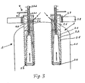
- the invention provides for additional cleaning in the space between each filter unit 3 between the outer and inner filters 3.1, 3.2 projecting ultrasonic transducer 7.
- a liquid such as a CIP liquid 8 is filled.
- the Fig. 5 shows that for drying the filter 3.1, 3.2, especially when it is fabric filter, but also in metal filters with emptied process space dry air is blown into the space inside the filter dome 1.1 through the air-permeable bottom 2.1.
- the flap 3.7 in the exhaust duct 3.8 is closed for a first cleaning step and then, as described in US Pat Fig. 1 and on the left side of the Fig. 2 is shown, via the fluid supply line 4.1 and the lance 4.2 cleaning fluid, such as air or an inert gas in the interior of the filter unit 3 and thus blown from the clean gas side through the filters 3.1, 3.2, so that on the process side of this filter adhering material, such as granulation , Coating material or the like is blown off the filters.
- this filter adhering material such as granulation , Coating material or the like is blown off the filters.
- Inner and outer filters 3.1, 3.2 are in a relative position, in which the annular gap 3.9 is closed on its underside.
- the filters 3.1, 3.2 are metal filters, then, as stated, an ultrasonic transducer projecting into the intermediate space between the outer and inner filters 3.1, 3.2 can be provided for further cleaning.
- an ultrasonic transducer projecting into the intermediate space between the outer and inner filters 3.1, 3.2 can be provided for further cleaning.
- the annular gap 3.9 is closed, further liquid is sprayed into the interior of the filter unit, namely more than can flow away through the filters, as a result of which liquid 8 in the interior is accumulated, which serves as a coupling medium for the ultrasound.
- the ultrasonic transducer 7 There is an activation of the ultrasonic transducer 7 and thus an effective cleaning on the inside of the external filter 3.1 and the outside of the inner filter 3.2 adhering material, such as coating material or the like, which migrates into the liquid 8.
- the in Fig. 1 is shown, carried out a cleaning of the outside of the outer filter 3.1 and the inside of the inner filter 3.2 by means of the Zielstrahlrutzs 6 through its liquid supply 6.1 via the lance 6.2 and the outlet nozzle 6.3 supplied liquid (CIP liquid).
- CIP liquid supplied liquid
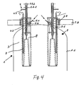
- the Fig. 6 On the right shows an alternative embodiment of a filter unit according to the invention in comparison to that on the left side in the embodiment of Fig. 1 to 5 realized and there described in detail filter unit.
- the filter unit 3 'right in the Fig. 6 is basically formed in the same way as the filter unit 3 and has the same elements, which are provided with the same reference numerals. Only the inner filter is 3.2 lower than the outer filter 3.1 to generate the slit gap 3.9 lowered instead of raised.
- Fig. 7 shows with the two alternatives of liftable or liftable inner filter 3.2, a further alternative embodiment, in which in the filter dome 1.1 above the filter 3 and the outer filter 3.1, a lowerable intermediate bottom is provided.
Landscapes
- Chemical & Material Sciences (AREA)
- Chemical Kinetics & Catalysis (AREA)
- Physics & Mathematics (AREA)
- Geometry (AREA)
- Filtering Of Dispersed Particles In Gases (AREA)
- Filtering Materials (AREA)
Priority Applications (1)
| Application Number | Priority Date | Filing Date | Title |
|---|---|---|---|
| PL08801803T PL2125153T3 (pl) | 2007-09-04 | 2008-09-03 | Układ filtracyjny do czyszczenia gazów procesowych obciążonych cząstkami i sposób czyszczenia jednostek filtracyjnych takiego układu filtracyjnego |
Applications Claiming Priority (2)
| Application Number | Priority Date | Filing Date | Title |
|---|---|---|---|
| DE102007041733A DE102007041733B4 (de) | 2007-09-04 | 2007-09-04 | Filteranordnung zum Reinigen von mit Partikeln verunreinigten Gasen und Verfahren zum Reinigen mindestens einer Filtereinheit |
| PCT/EP2008/007170 WO2009030462A1 (de) | 2007-09-04 | 2008-09-03 | Filteranordnung zum reinigen von partikelbelasteten prozessgasen und verfahren zum reinigen von filtereinheiten einer solchen filteranordnung |
Publications (2)
| Publication Number | Publication Date |
|---|---|
| EP2125153A1 EP2125153A1 (de) | 2009-12-02 |
| EP2125153B1 true EP2125153B1 (de) | 2010-11-10 |
Family
ID=40076595
Family Applications (1)
| Application Number | Title | Priority Date | Filing Date |
|---|---|---|---|
| EP08801803A Active EP2125153B1 (de) | 2007-09-04 | 2008-09-03 | Filteranordnung zum reinigen von partikelbelasteten prozessgasen und verfahren zum reinigen von filtereinheiten einer solchen filteranordnung |
Country Status (10)
| Country | Link |
|---|---|
| US (1) | US8231715B2 (enExample) |
| EP (1) | EP2125153B1 (enExample) |
| JP (2) | JP5174912B2 (enExample) |
| CN (1) | CN101848753B (enExample) |
| AT (1) | ATE487526T1 (enExample) |
| DE (2) | DE102007041733B4 (enExample) |
| DK (1) | DK2125153T3 (enExample) |
| ES (1) | ES2355866T3 (enExample) |
| PL (1) | PL2125153T3 (enExample) |
| WO (1) | WO2009030462A1 (enExample) |
Families Citing this family (14)
| Publication number | Priority date | Publication date | Assignee | Title |
|---|---|---|---|---|
| US8968438B2 (en) * | 2007-07-10 | 2015-03-03 | Innovalight, Inc. | Methods and apparatus for the in situ collection of nucleated particles |
| DE102007041733B4 (de) * | 2007-09-04 | 2009-09-03 | Hüttlin Gmbh | Filteranordnung zum Reinigen von mit Partikeln verunreinigten Gasen und Verfahren zum Reinigen mindestens einer Filtereinheit |
| IT1397570B1 (it) * | 2009-12-14 | 2013-01-16 | Agierre S A S Di Ruggero Vincenzo & C | Apparato e procedimento di trasporto pneumatico a vuoto per prodotti in polvere o simili. |
| US20130061757A1 (en) * | 2011-09-14 | 2013-03-14 | Abdulreidha A.T.A. Alsaffar | System for decontaminating industrial output gases |
| SG11201404341RA (en) * | 2012-02-03 | 2014-08-28 | Filtration Technology Coporation | Filter cleaning system and method |
| US9187190B1 (en) * | 2014-07-24 | 2015-11-17 | Hamilton Sundstrand Space Systems International, Inc. | Concentric split flow filter |
| CN105664615B (zh) * | 2016-01-13 | 2020-11-10 | 成都易态科技有限公司 | 过滤器 |
| KR101983017B1 (ko) * | 2017-03-07 | 2019-06-03 | 좋은전자주식회사 | 공기 청정기 |
| DE102018103157A1 (de) | 2018-02-13 | 2019-08-14 | Camfil Apc Gmbh | Geteilte Strömungsleitvorrichtung, Bausatz aus Grundkörper und Endstück einer Strömungsleitvorrichtung, Filteranlage und Verfahren zum Reinigen |
| KR102367161B1 (ko) * | 2018-09-10 | 2022-02-25 | 주식회사 엘지화학 | 메탈필터의 세척장치 및 세척방법 |
| DE102018221609A1 (de) | 2018-12-13 | 2020-06-18 | Robert Bosch Gmbh | Verfahren zur Herstellung eines Elektrodenfilms für einen Energiespeicher |
| DE102019214156A1 (de) * | 2019-09-17 | 2021-03-18 | Hüttlin Gmbh | Verfahren zur Dosierung einer Zielkomponente |
| GB2592267A (en) * | 2020-02-24 | 2021-08-25 | Altair Uk Ltd | Pulse nozzle for filter cleaning systems |
| CN113599913A (zh) * | 2021-06-30 | 2021-11-05 | 余姚海源机械设备厂 | 一种一体式自动除尘吸料机 |
Family Cites Families (34)
| Publication number | Priority date | Publication date | Assignee | Title |
|---|---|---|---|---|
| US3775950A (en) * | 1970-07-06 | 1973-12-04 | A Hallamore | Process air automatic self-cleaning air filtration system |
| DE7104981U (de) * | 1971-02-10 | 1971-07-29 | Kunststofftechnik Gmbh U Co Kg | Nassabscheider fuer luftreinigungsanlage |
| NL7401777A (enExample) * | 1973-02-14 | 1974-08-16 | ||
| US3838524A (en) * | 1973-03-19 | 1974-10-01 | Texaco Inc | Packing of particulate beds |
| US3898067A (en) * | 1973-10-04 | 1975-08-05 | Ind Clean Air Inc | Concentric cloth-tube air filter and dust collector |
| DE2551117C3 (de) * | 1975-11-14 | 1979-07-05 | Kastrup Kg, 4000 Duesseldorf | FUterorgan für einen Staubabscheider |
| DE2604493A1 (de) | 1976-02-03 | 1977-08-04 | Ind Clean Air Inc | Filteranordnung |
| GB1570431A (en) * | 1976-06-07 | 1980-07-02 | Monsanto Co | Fibre bed separator |
| DE2634965A1 (de) * | 1976-08-04 | 1978-02-09 | Sturm Gmbh A & E | Entstaubungsvorrichtung |
| US4145194A (en) * | 1977-12-07 | 1979-03-20 | Monsanto Company | Cylindrical fiber bed separator element with side-entry inlet duct to core of element |
| US4222748A (en) * | 1979-02-22 | 1980-09-16 | Monsanto Company | Electrostatically augmented fiber bed and method of using |
| DE3316527A1 (de) * | 1983-05-06 | 1984-11-08 | Henkel KGaA, 4000 Düsseldorf | Verfahren zum waschen der filterelemente eines gasfilters und vorrichtung zum durchfuehren des verfahrens |
| JPS59206024A (ja) * | 1983-05-10 | 1984-11-21 | フイルトレ−シヨン・ウオ−タ−・フイルタ−ズ・フオ−・アグリカルチヤ−・アンド・インダストリ−・リミテツド | フイルタ−部材及びフイルタ−装置 |
| ATE58646T1 (de) * | 1987-05-14 | 1990-12-15 | Miljoevern Umwelt Technik Gmbh | Verfahren und vorrichtung zum kontinuierlichen filtrieren von fluessigkeiten. |
| US5152890A (en) * | 1989-10-27 | 1992-10-06 | Pall Corporation | Filter device |
| DE4029994C2 (de) | 1990-09-21 | 1994-01-05 | Herbert Huettlin | Filterpatrone zum Entstauben von Gasen |
| DE4030086C1 (enExample) * | 1990-09-21 | 1991-12-12 | Herbert 7853 Steinen De Huettlin | |
| ES2095620T3 (es) * | 1992-05-26 | 1997-02-16 | Niro Aeromatic Ag | Instalacion y procedimiento para la limpieza en humedo de cartuchos de filtro en aparatos con capa turbulenta, secadores de pulverizacion e instalaciones de lecho fluidizado. |
| ATE211940T1 (de) * | 1997-10-31 | 2002-02-15 | Niro Atomizer As | Gasfilter und verfahren zur reinigung desselben |
| JP3322834B2 (ja) * | 1998-03-17 | 2002-09-09 | 株式会社周越テクニカ | 内燃機関用エアーフィルタ |
| FI108992B (fi) * | 1998-05-26 | 2002-05-15 | Metso Paper Inc | Menetelmä ja laite hiukkasten erottamiseksi ilmavirrasta |
| US6110248A (en) * | 1998-08-31 | 2000-08-29 | Shop Vac Corporation | Dual filter assembly for a vacuum cleaner |
| JP2003534893A (ja) | 2000-11-02 | 2003-11-25 | ニロ・アクティーゼルスカブ | 気体をろ過するフィルタ装置 |
| AU2001223511A1 (en) | 2000-11-29 | 2002-06-11 | Matthias Lubbers | Filter unit for purifying dust-laden process air |
| DE10124526C2 (de) * | 2001-05-19 | 2003-05-08 | Alfred Rachor | Filternde Entstauber mit Doppelfilterschlauchelementen und Druckluftabreinigung |
| DE10131108A1 (de) * | 2001-06-27 | 2003-01-09 | Mann & Hummel Filter | Filterelement mit Drainagerohr |
| ITBO20030486A1 (it) * | 2003-08-07 | 2005-02-08 | Ima Spa | Dispositivo granulatore per il trattamento di prodotti polverulenti. |
| DE102004000048B4 (de) * | 2004-11-17 | 2008-08-14 | Mann + Hummel Gmbh | Luftfilter |
| WO2006109172A1 (en) * | 2005-04-13 | 2006-10-19 | I.M.A. Industria Macchine Automatiche S.P.A. | Granulator device |
| TWI387478B (zh) * | 2005-08-31 | 2013-03-01 | Eaton Corp | 流體過濾器 |
| JP4734077B2 (ja) * | 2005-10-04 | 2011-07-27 | フロイント産業株式会社 | 粉粒体処理装置のフィルタ洗浄装置及びフィルタ洗浄方法 |
| US20070266859A1 (en) * | 2006-05-16 | 2007-11-22 | Mario Valenzi | Filter cleaning apparatus |
| US7632325B2 (en) * | 2006-11-28 | 2009-12-15 | General Electric Company | Filter assembly |
| DE102007041733B4 (de) * | 2007-09-04 | 2009-09-03 | Hüttlin Gmbh | Filteranordnung zum Reinigen von mit Partikeln verunreinigten Gasen und Verfahren zum Reinigen mindestens einer Filtereinheit |
-
2007
- 2007-09-04 DE DE102007041733A patent/DE102007041733B4/de active Active
-
2008
- 2008-09-03 CN CN200880114568.9A patent/CN101848753B/zh active Active
- 2008-09-03 EP EP08801803A patent/EP2125153B1/de active Active
- 2008-09-03 US US12/676,032 patent/US8231715B2/en active Active
- 2008-09-03 ES ES08801803T patent/ES2355866T3/es active Active
- 2008-09-03 DE DE502008001765T patent/DE502008001765D1/de active Active
- 2008-09-03 PL PL08801803T patent/PL2125153T3/pl unknown
- 2008-09-03 JP JP2010523317A patent/JP5174912B2/ja not_active Expired - Fee Related
- 2008-09-03 WO PCT/EP2008/007170 patent/WO2009030462A1/de not_active Ceased
- 2008-09-03 AT AT08801803T patent/ATE487526T1/de active
- 2008-09-03 DK DK08801803.1T patent/DK2125153T3/da active
-
2012
- 2012-07-26 JP JP2012165408A patent/JP5627129B2/ja not_active Expired - Fee Related
Also Published As
| Publication number | Publication date |
|---|---|
| DK2125153T3 (da) | 2011-02-28 |
| JP5174912B2 (ja) | 2013-04-03 |
| ATE487526T1 (de) | 2010-11-15 |
| DE502008001765D1 (de) | 2010-12-23 |
| ES2355866T3 (es) | 2011-03-31 |
| CN101848753B (zh) | 2014-02-26 |
| JP2010537814A (ja) | 2010-12-09 |
| PL2125153T3 (pl) | 2011-04-29 |
| DE102007041733B4 (de) | 2009-09-03 |
| JP2012228691A (ja) | 2012-11-22 |
| US8231715B2 (en) | 2012-07-31 |
| US20100212500A1 (en) | 2010-08-26 |
| DE102007041733A1 (de) | 2009-03-12 |
| CN101848753A (zh) | 2010-09-29 |
| EP2125153A1 (de) | 2009-12-02 |
| WO2009030462A1 (de) | 2009-03-12 |
| JP5627129B2 (ja) | 2014-11-19 |
Similar Documents
| Publication | Publication Date | Title |
|---|---|---|
| EP2125153B1 (de) | Filteranordnung zum reinigen von partikelbelasteten prozessgasen und verfahren zum reinigen von filtereinheiten einer solchen filteranordnung | |
| EP0476704B1 (de) | Verfahren zum Führen von Prozessgas in einer Apparatur sowie Apparatur zum Durchführen des Verfahrens | |
| EP0476169B1 (de) | Verfahren zum Reinigen eines Zyklons und damit reinigbarer Zyklon | |
| EP0572356A1 (de) | Vorrichtung und Verfahren zur Nassreinigung von Filterpatronen in Wirbelschichtapparaten, Strühtrocknern und Fliessbettanlagen | |
| DE19920466A1 (de) | Verfahren zum Abreinigen eines Innenraums einer Beschichtungskabine, insbesondere einer Pulverbeschichtungskabine sowie Beschichtungskabine, insbesondere Pulverbeschichtungskabine mit Reinigungseinrichtung | |
| DE2916152A1 (de) | Mehrstufen-vakuum-separator | |
| DE102017209077A1 (de) | Belüftungssystem und Verfahren für Kaltfräsmaschine | |
| EP1076593A1 (de) | Prozessapparatur mit abluftfilter | |
| DE4118433A1 (de) | Fliessbettapparatur zum behandeln partikelfoermigen gutes | |
| DE2254490C3 (de) | Vorrichtung zum Abscheiden von Abfallfasern aus einem Luftstrom | |
| DE102019200304A1 (de) | Filtersystem zur Aufreinigung von einem mit Partikeln beladenen Gasstrom und Anordnung zur Aufreinigung von einem mit Partikeln beladenen Gasstrom eines Fluidisierungsapparates mittels eines Filtersystems | |
| DE2429364A1 (de) | Tuchfilter | |
| EP1312419B1 (de) | Vorrichtung und Verfahren zur Reinigung der Gitterroste einer Lackierkabine | |
| DE10110098A1 (de) | Reinigungsvorrichtung für Farbaustraggeräte | |
| EP3890894B1 (de) | Auffangvorrichtung für spülmedien eines zerstäubers | |
| DE333576C (de) | Sandfilter | |
| DE3837763A1 (de) | Mischvorrichtung | |
| EP1457246B1 (de) | Produktbearbeitungsvorrichtung für staubende Materialien | |
| EP1095688A1 (de) | Staubfilter | |
| DE4336870C2 (de) | Filterpatrone | |
| EP0552454A2 (de) | Vorrichtung zum Reinigen von Filterelementen eines Gasfilters | |
| DE2406834A1 (de) | Reinigungsanlage fuer prallreinigung von verunreinigten granulaten | |
| DE202019104874U1 (de) | Mischmaschine | |
| DE1607681A1 (de) | Gasfilteranlage | |
| EP1314466A1 (de) | Verfahren zum Betreiben von Chromatographiesäulen und dafür geeignete Vorrichtung |
Legal Events
| Date | Code | Title | Description |
|---|---|---|---|
| PUAI | Public reference made under article 153(3) epc to a published international application that has entered the european phase |
Free format text: ORIGINAL CODE: 0009012 |
|
| 17P | Request for examination filed |
Effective date: 20090728 |
|
| AK | Designated contracting states |
Kind code of ref document: A1 Designated state(s): AT BE BG CH CY CZ DE DK EE ES FI FR GB GR HR HU IE IS IT LI LT LU LV MC MT NL NO PL PT RO SE SI SK TR |
|
| 17Q | First examination report despatched |
Effective date: 20100625 |
|
| GRAP | Despatch of communication of intention to grant a patent |
Free format text: ORIGINAL CODE: EPIDOSNIGR1 |
|
| GRAS | Grant fee paid |
Free format text: ORIGINAL CODE: EPIDOSNIGR3 |
|
| GRAA | (expected) grant |
Free format text: ORIGINAL CODE: 0009210 |
|
| AK | Designated contracting states |
Kind code of ref document: B1 Designated state(s): AT BE BG CH CY CZ DE DK EE ES FI FR GB GR HR HU IE IS IT LI LT LU LV MC MT NL NO PL PT RO SE SI SK TR |
|
| REG | Reference to a national code |
Ref country code: GB Ref legal event code: FG4D Free format text: NOT ENGLISH |
|
| REG | Reference to a national code |
Ref country code: CH Ref legal event code: EP |
|
| REG | Reference to a national code |
Ref country code: IE Ref legal event code: FG4D Free format text: LANGUAGE OF EP DOCUMENT: GERMAN |
|
| REF | Corresponds to: |
Ref document number: 502008001765 Country of ref document: DE Date of ref document: 20101223 Kind code of ref document: P |
|
| REG | Reference to a national code |
Ref country code: CH Ref legal event code: NV Representative=s name: TROESCH SCHEIDEGGER WERNER AG |
|
| REG | Reference to a national code |
Ref country code: DK Ref legal event code: T3 |
|
| REG | Reference to a national code |
Ref country code: NL Ref legal event code: VDEP Effective date: 20101110 |
|
| REG | Reference to a national code |
Ref country code: ES Ref legal event code: FG2A Ref document number: 2355866 Country of ref document: ES Kind code of ref document: T3 Effective date: 20110331 |
|
| LTIE | Lt: invalidation of european patent or patent extension |
Effective date: 20101110 |
|
| PG25 | Lapsed in a contracting state [announced via postgrant information from national office to epo] |
Ref country code: LT Free format text: LAPSE BECAUSE OF FAILURE TO SUBMIT A TRANSLATION OF THE DESCRIPTION OR TO PAY THE FEE WITHIN THE PRESCRIBED TIME-LIMIT Effective date: 20101110 Ref country code: NO Free format text: LAPSE BECAUSE OF FAILURE TO SUBMIT A TRANSLATION OF THE DESCRIPTION OR TO PAY THE FEE WITHIN THE PRESCRIBED TIME-LIMIT Effective date: 20110210 |
|
| REG | Reference to a national code |
Ref country code: PL Ref legal event code: T3 |
|
| PG25 | Lapsed in a contracting state [announced via postgrant information from national office to epo] |
Ref country code: BG Free format text: LAPSE BECAUSE OF FAILURE TO SUBMIT A TRANSLATION OF THE DESCRIPTION OR TO PAY THE FEE WITHIN THE PRESCRIBED TIME-LIMIT Effective date: 20110210 Ref country code: NL Free format text: LAPSE BECAUSE OF FAILURE TO SUBMIT A TRANSLATION OF THE DESCRIPTION OR TO PAY THE FEE WITHIN THE PRESCRIBED TIME-LIMIT Effective date: 20101110 Ref country code: FI Free format text: LAPSE BECAUSE OF FAILURE TO SUBMIT A TRANSLATION OF THE DESCRIPTION OR TO PAY THE FEE WITHIN THE PRESCRIBED TIME-LIMIT Effective date: 20101110 Ref country code: LV Free format text: LAPSE BECAUSE OF FAILURE TO SUBMIT A TRANSLATION OF THE DESCRIPTION OR TO PAY THE FEE WITHIN THE PRESCRIBED TIME-LIMIT Effective date: 20101110 Ref country code: PT Free format text: LAPSE BECAUSE OF FAILURE TO SUBMIT A TRANSLATION OF THE DESCRIPTION OR TO PAY THE FEE WITHIN THE PRESCRIBED TIME-LIMIT Effective date: 20110310 Ref country code: CY Free format text: LAPSE BECAUSE OF FAILURE TO SUBMIT A TRANSLATION OF THE DESCRIPTION OR TO PAY THE FEE WITHIN THE PRESCRIBED TIME-LIMIT Effective date: 20101110 Ref country code: IS Free format text: LAPSE BECAUSE OF FAILURE TO SUBMIT A TRANSLATION OF THE DESCRIPTION OR TO PAY THE FEE WITHIN THE PRESCRIBED TIME-LIMIT Effective date: 20110310 Ref country code: SE Free format text: LAPSE BECAUSE OF FAILURE TO SUBMIT A TRANSLATION OF THE DESCRIPTION OR TO PAY THE FEE WITHIN THE PRESCRIBED TIME-LIMIT Effective date: 20101110 Ref country code: HR Free format text: LAPSE BECAUSE OF FAILURE TO SUBMIT A TRANSLATION OF THE DESCRIPTION OR TO PAY THE FEE WITHIN THE PRESCRIBED TIME-LIMIT Effective date: 20101110 Ref country code: SI Free format text: LAPSE BECAUSE OF FAILURE TO SUBMIT A TRANSLATION OF THE DESCRIPTION OR TO PAY THE FEE WITHIN THE PRESCRIBED TIME-LIMIT Effective date: 20101110 |
|
| REG | Reference to a national code |
Ref country code: IE Ref legal event code: FD4D |
|
| PG25 | Lapsed in a contracting state [announced via postgrant information from national office to epo] |
Ref country code: GR Free format text: LAPSE BECAUSE OF FAILURE TO SUBMIT A TRANSLATION OF THE DESCRIPTION OR TO PAY THE FEE WITHIN THE PRESCRIBED TIME-LIMIT Effective date: 20110211 |
|
| PG25 | Lapsed in a contracting state [announced via postgrant information from national office to epo] |
Ref country code: EE Free format text: LAPSE BECAUSE OF FAILURE TO SUBMIT A TRANSLATION OF THE DESCRIPTION OR TO PAY THE FEE WITHIN THE PRESCRIBED TIME-LIMIT Effective date: 20101110 Ref country code: IE Free format text: LAPSE BECAUSE OF FAILURE TO SUBMIT A TRANSLATION OF THE DESCRIPTION OR TO PAY THE FEE WITHIN THE PRESCRIBED TIME-LIMIT Effective date: 20101110 Ref country code: CZ Free format text: LAPSE BECAUSE OF FAILURE TO SUBMIT A TRANSLATION OF THE DESCRIPTION OR TO PAY THE FEE WITHIN THE PRESCRIBED TIME-LIMIT Effective date: 20101110 |
|
| PG25 | Lapsed in a contracting state [announced via postgrant information from national office to epo] |
Ref country code: SK Free format text: LAPSE BECAUSE OF FAILURE TO SUBMIT A TRANSLATION OF THE DESCRIPTION OR TO PAY THE FEE WITHIN THE PRESCRIBED TIME-LIMIT Effective date: 20101110 Ref country code: RO Free format text: LAPSE BECAUSE OF FAILURE TO SUBMIT A TRANSLATION OF THE DESCRIPTION OR TO PAY THE FEE WITHIN THE PRESCRIBED TIME-LIMIT Effective date: 20101110 |
|
| PLBE | No opposition filed within time limit |
Free format text: ORIGINAL CODE: 0009261 |
|
| STAA | Information on the status of an ep patent application or granted ep patent |
Free format text: STATUS: NO OPPOSITION FILED WITHIN TIME LIMIT |
|
| 26N | No opposition filed |
Effective date: 20110811 |
|
| REG | Reference to a national code |
Ref country code: DE Ref legal event code: R097 Ref document number: 502008001765 Country of ref document: DE Effective date: 20110811 |
|
| BERE | Be: lapsed |
Owner name: HUTTLIN G.M.B.H. Effective date: 20110930 |
|
| PG25 | Lapsed in a contracting state [announced via postgrant information from national office to epo] |
Ref country code: MC Free format text: LAPSE BECAUSE OF NON-PAYMENT OF DUE FEES Effective date: 20110930 |
|
| PG25 | Lapsed in a contracting state [announced via postgrant information from national office to epo] |
Ref country code: BE Free format text: LAPSE BECAUSE OF NON-PAYMENT OF DUE FEES Effective date: 20110930 |
|
| REG | Reference to a national code |
Ref country code: DE Ref legal event code: R082 Ref document number: 502008001765 Country of ref document: DE |
|
| PG25 | Lapsed in a contracting state [announced via postgrant information from national office to epo] |
Ref country code: MT Free format text: LAPSE BECAUSE OF FAILURE TO SUBMIT A TRANSLATION OF THE DESCRIPTION OR TO PAY THE FEE WITHIN THE PRESCRIBED TIME-LIMIT Effective date: 20101110 |
|
| PG25 | Lapsed in a contracting state [announced via postgrant information from national office to epo] |
Ref country code: LU Free format text: LAPSE BECAUSE OF NON-PAYMENT OF DUE FEES Effective date: 20110903 |
|
| PG25 | Lapsed in a contracting state [announced via postgrant information from national office to epo] |
Ref country code: HU Free format text: LAPSE BECAUSE OF FAILURE TO SUBMIT A TRANSLATION OF THE DESCRIPTION OR TO PAY THE FEE WITHIN THE PRESCRIBED TIME-LIMIT Effective date: 20101110 |
|
| REG | Reference to a national code |
Ref country code: AT Ref legal event code: MM01 Ref document number: 487526 Country of ref document: AT Kind code of ref document: T Effective date: 20130903 |
|
| PG25 | Lapsed in a contracting state [announced via postgrant information from national office to epo] |
Ref country code: AT Free format text: LAPSE BECAUSE OF NON-PAYMENT OF DUE FEES Effective date: 20130903 |
|
| REG | Reference to a national code |
Ref country code: FR Ref legal event code: PLFP Year of fee payment: 9 |
|
| REG | Reference to a national code |
Ref country code: FR Ref legal event code: PLFP Year of fee payment: 10 |
|
| REG | Reference to a national code |
Ref country code: FR Ref legal event code: PLFP Year of fee payment: 11 |
|
| REG | Reference to a national code |
Ref country code: DE Ref legal event code: R082 Ref document number: 502008001765 Country of ref document: DE Representative=s name: DREISS PATENTANWAELTE PARTG MBB, DE |
|
| PGFP | Annual fee paid to national office [announced via postgrant information from national office to epo] |
Ref country code: TR Payment date: 20220826 Year of fee payment: 15 Ref country code: DK Payment date: 20220926 Year of fee payment: 15 |
|
| PGFP | Annual fee paid to national office [announced via postgrant information from national office to epo] |
Ref country code: PL Payment date: 20220819 Year of fee payment: 15 |
|
| REG | Reference to a national code |
Ref country code: DK Ref legal event code: EBP Effective date: 20230930 |
|
| PG25 | Lapsed in a contracting state [announced via postgrant information from national office to epo] |
Ref country code: DK Free format text: LAPSE BECAUSE OF NON-PAYMENT OF DUE FEES Effective date: 20230930 |
|
| PG25 | Lapsed in a contracting state [announced via postgrant information from national office to epo] |
Ref country code: PL Free format text: LAPSE BECAUSE OF NON-PAYMENT OF DUE FEES Effective date: 20230903 |
|
| PG25 | Lapsed in a contracting state [announced via postgrant information from national office to epo] |
Ref country code: PL Free format text: LAPSE BECAUSE OF NON-PAYMENT OF DUE FEES Effective date: 20230903 Ref country code: DK Free format text: LAPSE BECAUSE OF NON-PAYMENT OF DUE FEES Effective date: 20230930 |
|
| REG | Reference to a national code |
Ref country code: CH Ref legal event code: U11 Free format text: ST27 STATUS EVENT CODE: U-0-0-U10-U11 (AS PROVIDED BY THE NATIONAL OFFICE) Effective date: 20251001 |
|
| PGFP | Annual fee paid to national office [announced via postgrant information from national office to epo] |
Ref country code: DE Payment date: 20250919 Year of fee payment: 18 |
|
| PGFP | Annual fee paid to national office [announced via postgrant information from national office to epo] |
Ref country code: GB Payment date: 20250923 Year of fee payment: 18 |
|
| PGFP | Annual fee paid to national office [announced via postgrant information from national office to epo] |
Ref country code: FR Payment date: 20250926 Year of fee payment: 18 |
|
| PGFP | Annual fee paid to national office [announced via postgrant information from national office to epo] |
Ref country code: IT Payment date: 20250930 Year of fee payment: 18 |
|
| PGFP | Annual fee paid to national office [announced via postgrant information from national office to epo] |
Ref country code: CH Payment date: 20251001 Year of fee payment: 18 |
|
| PGFP | Annual fee paid to national office [announced via postgrant information from national office to epo] |
Ref country code: ES Payment date: 20251020 Year of fee payment: 18 |