EP2124041A2 - LED-Lichtmatrix mit Pulsmitteln - Google Patents
LED-Lichtmatrix mit Pulsmitteln Download PDFInfo
- Publication number
- EP2124041A2 EP2124041A2 EP09160376A EP09160376A EP2124041A2 EP 2124041 A2 EP2124041 A2 EP 2124041A2 EP 09160376 A EP09160376 A EP 09160376A EP 09160376 A EP09160376 A EP 09160376A EP 2124041 A2 EP2124041 A2 EP 2124041A2
- Authority
- EP
- European Patent Office
- Prior art keywords
- led light
- light matrix
- matrix
- leds
- led
- Prior art date
- Legal status (The legal status is an assumption and is not a legal conclusion. Google has not performed a legal analysis and makes no representation as to the accuracy of the status listed.)
- Granted
Links
Images


Classifications
-
- F—MECHANICAL ENGINEERING; LIGHTING; HEATING; WEAPONS; BLASTING
- F21—LIGHTING
- F21V—FUNCTIONAL FEATURES OR DETAILS OF LIGHTING DEVICES OR SYSTEMS THEREOF; STRUCTURAL COMBINATIONS OF LIGHTING DEVICES WITH OTHER ARTICLES, NOT OTHERWISE PROVIDED FOR
- F21V14/00—Controlling the distribution of the light emitted by adjustment of elements
-
- G—PHYSICS
- G01—MEASURING; TESTING
- G01N—INVESTIGATING OR ANALYSING MATERIALS BY DETERMINING THEIR CHEMICAL OR PHYSICAL PROPERTIES
- G01N21/00—Investigating or analysing materials by the use of optical means, i.e. using sub-millimetre waves, infrared, visible or ultraviolet light
- G01N21/84—Systems specially adapted for particular applications
- G01N21/88—Investigating the presence of flaws or contamination
- G01N21/8806—Specially adapted optical and illumination features
-
- G—PHYSICS
- G01—MEASURING; TESTING
- G01N—INVESTIGATING OR ANALYSING MATERIALS BY DETERMINING THEIR CHEMICAL OR PHYSICAL PROPERTIES
- G01N21/00—Investigating or analysing materials by the use of optical means, i.e. using sub-millimetre waves, infrared, visible or ultraviolet light
- G01N21/84—Systems specially adapted for particular applications
- G01N21/86—Investigating moving sheets
-
- G—PHYSICS
- G01—MEASURING; TESTING
- G01N—INVESTIGATING OR ANALYSING MATERIALS BY DETERMINING THEIR CHEMICAL OR PHYSICAL PROPERTIES
- G01N21/00—Investigating or analysing materials by the use of optical means, i.e. using sub-millimetre waves, infrared, visible or ultraviolet light
- G01N21/84—Systems specially adapted for particular applications
- G01N21/88—Investigating the presence of flaws or contamination
- G01N21/89—Investigating the presence of flaws or contamination in moving material, e.g. running paper or textiles
- G01N21/8901—Optical details; Scanning details
-
- H—ELECTRICITY
- H10—SEMICONDUCTOR DEVICES; ELECTRIC SOLID-STATE DEVICES NOT OTHERWISE PROVIDED FOR
- H10H—INORGANIC LIGHT-EMITTING SEMICONDUCTOR DEVICES HAVING POTENTIAL BARRIERS
- H10H20/00—Individual inorganic light-emitting semiconductor devices having potential barriers, e.g. light-emitting diodes [LED]
- H10H20/80—Constructional details
Definitions
- the invention relates to a LED light matrix equipped with impulse means for illuminating a moving object in a selected area from an oblique direction for video imaging, said LED light matrix including a group of LEDs each equipped with optics for focusing the light produced by the LED, and the group being located substantially obliquely relative to the object to be illuminated.
- a paper machine has a numerous amount of objects to be monitored by video cameras where both imaging and illuminating are arranged from outside the web since imaging equipment cannot be set on top of the web. Imaging set outside the web as well as illumination always take place obliquely relative to the web. Then there is even too much light within a close range and too little light at a certain distance from the web edge.
- the efficiency of focused illumination reduces proportionally to the square of the distance, but the intensity of light leaving the surface of an object still decreases to the third power.
- the effective imaging area remains rather small and often the image cannot be extended even near to the machine center point.
- Imaging of a quickly moving web or object with a LED stroboscope light is known, for example, from publications WO 2007/096475 , WO 2004/063664 and US 5,936,353 , as well as from Finnish patent application 20065570 .
- the objective of this invention is to provide an improvement in imaging conditions and even to enable imaging further within the machine.
- the characteristic features of the LED light matrix according to this invention are set forth in the appended claim 1.
- the efficiency of a LED light unit when provided with impulses remains a fraction compared to a halogen lamp with a corresponding efficiency; thus the fire risk is eliminated.
- at least part of the LEDs emit monochromatic light the color of which has been selected according to the object to be illuminated. In many cases, a green color is advantageous for white paper and white is advantageous for brown paper.
- At least two types, as for the radiation beam, of LED components with respective optics are used, i.e. separate lenses of two or more types are generally used with similar LEDs to create different beams.
- the matrix can always be assembled from these beam types in such a way that an intensity distribution that is emphasized at the furthest end is achieved.
- the intensity varies in the selected illuminated area according to a coefficient which is in a range of 2 - 10. In practice, a near edge thus receives light only a fraction compared to a selected furthest point.
- the LEDs of the matrix are oriented in either one or more planes for achieving a desired intensity distribution.
- the matrix has curvature in either one or two planes.
- the light fixture can be assembled from more than one matrix each of which can be equipped with desired illumination beams and each can be separately oriented to the area to be illuminated for creating an optimum imaging area illumination.
- a useful method is to divide the matrix into bands which are separately oriented.
- the imaging area and hence the illuminated area, is a rectangular where the ratio of the longer side relative to the shorter side is within a range of 1.25 - 5.
- the illuminated area corresponds at least to the imaging area of the camera but it can also be emphasized only to the illumination of the object to be imaged, which area can have a different shape compared to the imaging area of the camera.
- a LED light matrix is advantageously located in a camera casing, which avoids a separate unit with the respective auxiliary functions (e.g. cleaning).
- a LED light matrix can also be located in a separate light fixture casing, in which case it can be utilized for improving the illumination of already existing cameras. Similarly, when using very high efficiencies, the LED surface area can grow so large that the use of a separate light fixture casing is justifiable.
- a light matrix 14 in a light unit 12 illuminates an object 10 (a paper machine web, for example) in a selected area 11.
- the web travels orthogonally to the imaging plane the selected area 11 being thus a narrow band extending from the web edge toward the center.
- the length of the impulses is 10 - 500 ⁇ s being always substantially shorter than the camera's shutter speed and the impulses are adapted to correspond to a distance of 1 - 5 mm, advantageously of 1 - 2 mm, at the web speed concerned.
- the impulses are accurately timed to operate while the camera shutter is open, or the common time is accurately regulated in some other way. It is advantageous to time the impulse completely for the time of the shutter's open position ( Figure 8 ), which allows utilizing fully the light impulse.
- opening and closing of an electronic shutter are usually sliding events over an image matrix.
- the light matrix 14 comprises LEDs 15, 16 with lenses in six rows.
- the circled LEDs 15 are LEDs with narrow beams and the other ones are LEDs 16 with wide beams. With this arrangement, too, a better intensity distribution than before can be achieved for the selected area.
- High-efficiency LEDs, efficiency class 6 W (April 2009), are used here, but such that can be momentarily loaded by means of pulsing with a notably higher efficiency.
- One LED supplier is Philips (NL) and one trademark is Luxeon ® , for example type K2 1000 mA - cool white LXK2_PW14_T00 or LXML_PWC1_0100.
- Lenses are used on top of the LEDs to focus the light in a desired beam, for example the following: the oval lens is Carclo 10415 (Carclo Technical Plastics, GB) and the spot lens is Carclo 10412. Another alternative is LEDIL OY(FI) "CRS SQUARE lenses for CREE XR/-E LEDs”.
- Figures 3a and 3b show the illumination area of a wide-beam and a narrow-beam LED in an orthogonal plane. Optics related to the LED enables different radiation beams which can have directivity in either one or two dimensions.
- the intensity distribution is asymmetric in the selected area 11. Illumination intensity increases from the web edge up to the other end. For a camera sensor, the intensity is constant in an ideal case, but it is naturally sufficient that the variation is clearly within the sensor dynamics.
- the light matrix 14 can naturally be implemented as a separate unit, which is also sometimes necessary, but advantageously it is integrated to a camera unit 12. This includes common auxiliary equipment, for example, cooling elements and glass cleaning means (not shown).
- the light matrix 14 is fitted to a camera casing 12.1 having a glass plate 12.2 at its end.
- the camera 22 images through an aperture 20 left in the matrix, Figure 4 .
- the aperture 20 is arranged asymmetrically, which allows obtaining proportionally more LEDs that are naturally oriented distantly, than LEDs that are oriented to a near distance.
- the matrix comprises several discrete strips 18, which are circuit boards supporting the LEDs. These strips 18 form a curve that curves down increasingly steeply, Figure 5 . At the other end, one or more strips can be slightly bent to the opposite direction for focusing the radiation optimally.
- the LEDs emit a green light which has a great difference of sensibility between the human eye and the camera sensor.
- the LEDs are controlled in a known way by an impulse oscillator which is synchronized with the camera.
- the LED light matrix 14 includes advantageously 100 - 300 LEDs 15, 16.
- the LED light in the camera casing uses 117 LEDs à 6 W (nominal efficiency 3 W), i.e. a total efficiency of 712 W.
- the dimensions of the light fixture are 200 x 200 x 300 (L) mm. Functionally similar parts are referred to using the same reference numbers as above.
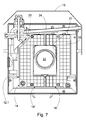
- the light fixture is also integrated to a camera unit 12 located in a thermally insulated casing 12.1 provided with cooling, which is indicated schematically with reference number 26. Simple compressed air cooling is sufficient up to an environmental temperature of 60°C and a vortex cooler is used in hotter conditions (up to 115°C). Despite the high nominal efficiency of the LED light fixture, its continuous efficiency is only 30 W.
- the light matrix 14 is here integrated to the camera unit 12, which includes shared cooling elements 26 and glass cleaning means, such as a wiper 24 and a cleaning water supply 23.
- this application also has a glass plate 12.2 which covers the two-part light matrix 14.
- the camera 22 images through an aperture 20 left in the light matrix 14.
- the camera casing 12.1 has a splash guard 12 on top and its wall is provided with PU insulation 27, Figure 7 .
- the parts 18' and 18" of the light matrix 14 are orientable, i.e. the matrix has two halves which can be individually oriented to a desired direction (thus this corresponds to a curved construction).
- LED matrices can be fitted with horizontal, vertical and spot lenses.
- the left matrix part 18' is equipped with spot lenses and oriented to the web edge.
- the matrix part 18" uses a vertical lens on top of each LED, which is oriented to the direction of a roll (thus this corresponds to wide-beam and directional optics).
- the casing 12.1 can be turned by 90° and simultaneously the camera is turned inside to the opposite direction so that the image remains constant but the directionability of the light matrix 14 changes vertical. In this way the matrix halves can be oriented also in the up/down direction in case the camera position requires it.
- a separate LED light fixture has a total of 3 elements of 63 LEDs each of which provides an impulse efficiency of 380 W with the actual power consumption being only 10 W.
- the elements are separately oriented as above and they are equipped with desired optics.
- a LED light fixture includes synchronization means which are connected to the camera shutter.
Landscapes
- Physics & Mathematics (AREA)
- Health & Medical Sciences (AREA)
- Life Sciences & Earth Sciences (AREA)
- Chemical & Material Sciences (AREA)
- Analytical Chemistry (AREA)
- Biochemistry (AREA)
- General Health & Medical Sciences (AREA)
- General Physics & Mathematics (AREA)
- Immunology (AREA)
- Pathology (AREA)
- Engineering & Computer Science (AREA)
- Textile Engineering (AREA)
- General Engineering & Computer Science (AREA)
- Studio Devices (AREA)
- Non-Portable Lighting Devices Or Systems Thereof (AREA)
Priority Applications (2)
| Application Number | Priority Date | Filing Date | Title |
|---|---|---|---|
| DE202009018154U DE202009018154U1 (de) | 2008-05-20 | 2009-05-15 | Mit Impulsmitteln ausgerüstete LED-Leuchte Matrix |
| FI20100541U FI9167U1 (fi) | 2008-05-20 | 2010-12-20 | Pulssitusvälinein varustettu LED-valaisinmatriisi |
Applications Claiming Priority (1)
| Application Number | Priority Date | Filing Date | Title |
|---|---|---|---|
| FI20085478A FI123335B (fi) | 2008-05-20 | 2008-05-20 | Pulssitusvälinein varustettu LED- valaisinmatriisi |
Publications (3)
| Publication Number | Publication Date |
|---|---|
| EP2124041A2 true EP2124041A2 (de) | 2009-11-25 |
| EP2124041A3 EP2124041A3 (de) | 2014-01-01 |
| EP2124041B1 EP2124041B1 (de) | 2020-05-06 |
Family
ID=39523129
Family Applications (1)
| Application Number | Title | Priority Date | Filing Date |
|---|---|---|---|
| EP09160376.1A Active EP2124041B1 (de) | 2008-05-20 | 2009-05-15 | Einheit mit einer Kamera und einer Led-Leuchtmatrix mit Impulsmittel |
Country Status (4)
| Country | Link |
|---|---|
| US (1) | US8197078B2 (de) |
| EP (1) | EP2124041B1 (de) |
| DE (2) | DE09160376T1 (de) |
| FI (2) | FI123335B (de) |
Cited By (2)
| Publication number | Priority date | Publication date | Assignee | Title |
|---|---|---|---|---|
| US20110226434A1 (en) * | 2008-11-25 | 2011-09-22 | Metso Automation Oy | Method for guiding web patching using a re-reeler and a corresponding system |
| EP4062094B1 (de) * | 2019-11-20 | 2026-04-15 | Procemex Oy | Led-matrix-beleuchtungsvorrichtung |
Families Citing this family (3)
| Publication number | Priority date | Publication date | Assignee | Title |
|---|---|---|---|---|
| JP2018159650A (ja) * | 2017-03-23 | 2018-10-11 | 株式会社Screenホールディングス | 照明装置、照明方法および撮像装置 |
| FI129791B (en) * | 2019-04-17 | 2022-08-31 | Valmet Automation Oy | System and method for measuring a moving layered sheet structure in a paperboard process |
| WO2024067240A1 (zh) * | 2022-09-26 | 2024-04-04 | 苏州欧普照明有限公司 | 减影台灯 |
Citations (3)
| Publication number | Priority date | Publication date | Assignee | Title |
|---|---|---|---|---|
| US5936353A (en) | 1996-04-03 | 1999-08-10 | Pressco Technology Inc. | High-density solid-state lighting array for machine vision applications |
| WO2004063664A1 (de) | 2003-01-16 | 2004-07-29 | Parsytec Computer Gmbh | Optisches verfahren und vorrichtung zur oberflächenkontrolle |
| WO2007096475A1 (en) | 2006-02-22 | 2007-08-30 | Viconsys Oy | Method for monitoring a rapidly-moving paper web and corresponding system |
Family Cites Families (20)
| Publication number | Priority date | Publication date | Assignee | Title |
|---|---|---|---|---|
| US1926292A (en) * | 1930-05-31 | 1933-09-12 | Cambridge Instr Company Inc | Paper-making machine and method |
| CH552197A (de) * | 1972-11-24 | 1974-07-31 | Bbc Brown Boveri & Cie | Einrichtung zum messen der rauhigkeit einer oberflaeche. |
| US4882498A (en) * | 1987-10-09 | 1989-11-21 | Pressco, Inc. | Pulsed-array video inspection lighting system |
| JPH01112212A (ja) * | 1987-10-26 | 1989-04-28 | Fuji Photo Film Co Ltd | オートフォーカス用投光装置 |
| GB9214664D0 (en) | 1992-07-10 | 1992-08-19 | Wiggins Teape Group Ltd | Watermark detection |
| TW330233B (en) * | 1997-01-23 | 1998-04-21 | Philips Eloctronics N V | Luminary |
| US7186003B2 (en) * | 1997-08-26 | 2007-03-06 | Color Kinetics Incorporated | Light-emitting diode based products |
| US6788411B1 (en) * | 1999-07-08 | 2004-09-07 | Ppt Vision, Inc. | Method and apparatus for adjusting illumination angle |
| DE50113144D1 (de) * | 2000-06-28 | 2007-11-29 | Bosch Gmbh Robert | Vorrichtung zum bildlichen Erfassen von Stückgütern |
| GB0020766D0 (en) * | 2000-08-24 | 2000-10-11 | Rozenberg Simon G | Improvements in lamps luminaires and lighting systems |
| FR2822553B3 (fr) | 2001-03-20 | 2003-04-25 | View Eng | Procede et systeme pour eclairer un objet avec une lumiere focalisee sous divers angles d'incidence et source de lumiere a plusieurs couleurs destinee a etre utilisee dans ce systeme |
| FI116241B (fi) * | 2002-05-06 | 2005-10-14 | Metso Automation Oy | Menetelmä ja laitteisto paperikoneen viiraosan retention määrittämiseksi |
| KR100966544B1 (ko) * | 2002-12-24 | 2010-06-29 | 주식회사 포스코 | 코일 표면의 선형 요철성 결함 검출 장치 |
| US6910794B2 (en) * | 2003-04-25 | 2005-06-28 | Guide Corporation | Automotive lighting assembly cooling system |
| US7334918B2 (en) * | 2003-05-07 | 2008-02-26 | Bayco Products, Ltd. | LED lighting array for a portable task light |
| US6921182B2 (en) * | 2003-05-13 | 2005-07-26 | Solaroasis | Efficient LED lamp for enhancing commercial and home plant growth |
| US7140753B2 (en) * | 2004-08-11 | 2006-11-28 | Harvatek Corporation | Water-cooling heat dissipation device adopted for modulized LEDs |
| US7433590B2 (en) * | 2005-04-19 | 2008-10-07 | Accu-Sort Systems, Inc. | Method of low intensity lighting for high speed image capture |
| CN100437275C (zh) * | 2005-05-18 | 2008-11-26 | 鸿富锦精密工业(深圳)有限公司 | 直下式背光模组 |
| EP1783080A1 (de) * | 2005-11-08 | 2007-05-09 | Lorillard Licensing Company, LLC | Optische Datenerfassung und Qualitätskontrolle |
-
2008
- 2008-05-20 FI FI20085478A patent/FI123335B/fi active IP Right Grant
-
2009
- 2009-05-15 EP EP09160376.1A patent/EP2124041B1/de active Active
- 2009-05-15 US US12/466,436 patent/US8197078B2/en not_active Expired - Fee Related
- 2009-05-15 DE DE09160376T patent/DE09160376T1/de active Pending
- 2009-05-15 DE DE202009018154U patent/DE202009018154U1/de not_active Expired - Lifetime
-
2010
- 2010-12-20 FI FI20100541U patent/FI9167U1/fi not_active IP Right Cessation
Patent Citations (3)
| Publication number | Priority date | Publication date | Assignee | Title |
|---|---|---|---|---|
| US5936353A (en) | 1996-04-03 | 1999-08-10 | Pressco Technology Inc. | High-density solid-state lighting array for machine vision applications |
| WO2004063664A1 (de) | 2003-01-16 | 2004-07-29 | Parsytec Computer Gmbh | Optisches verfahren und vorrichtung zur oberflächenkontrolle |
| WO2007096475A1 (en) | 2006-02-22 | 2007-08-30 | Viconsys Oy | Method for monitoring a rapidly-moving paper web and corresponding system |
Cited By (3)
| Publication number | Priority date | Publication date | Assignee | Title |
|---|---|---|---|---|
| US20110226434A1 (en) * | 2008-11-25 | 2011-09-22 | Metso Automation Oy | Method for guiding web patching using a re-reeler and a corresponding system |
| US8506758B2 (en) * | 2008-11-25 | 2013-08-13 | Metso Automation Oy | System for guiding web patching using a re-reeler |
| EP4062094B1 (de) * | 2019-11-20 | 2026-04-15 | Procemex Oy | Led-matrix-beleuchtungsvorrichtung |
Also Published As
| Publication number | Publication date |
|---|---|
| FIU20100541U0 (fi) | 2010-12-20 |
| EP2124041B1 (de) | 2020-05-06 |
| FI20085478A0 (fi) | 2008-05-20 |
| US20090290323A1 (en) | 2009-11-26 |
| FI9167U1 (fi) | 2011-04-15 |
| DE202009018154U1 (de) | 2011-03-17 |
| FI123335B (fi) | 2013-02-28 |
| FI20085478L (fi) | 2009-11-21 |
| EP2124041A3 (de) | 2014-01-01 |
| DE09160376T1 (de) | 2011-04-14 |
| US8197078B2 (en) | 2012-06-12 |
Similar Documents
| Publication | Publication Date | Title |
|---|---|---|
| EP2124041B1 (de) | Einheit mit einer Kamera und einer Led-Leuchtmatrix mit Impulsmittel | |
| US9470397B2 (en) | Light collecting system with a number of reflector pairs | |
| DE60303328T2 (de) | Ringförmige Lichtquelle | |
| US6161941A (en) | Light array system and method for illumination of objects imaged by imaging systems | |
| US6598994B1 (en) | Multi-angle inspection of manufactured products | |
| DK2394095T3 (en) | A lighting device with multiple light sources and a reflection arrangement and reflector | |
| EP3115682A1 (de) | Lichtleitende säule und fahrzeuglampe damit | |
| EP1653255A3 (de) | Linse mit einstellbarem Strahl für Unterwasserlicht | |
| US9377166B2 (en) | Lens, LED module and illumination system having same | |
| CN110520672B (zh) | 高功率led强力照明灯及用于体育场照明的强力照明灯设施 | |
| JP7138571B2 (ja) | シート要素加工機のための品質管理ステーション及び品質管理ステーションのための照明ユニット | |
| CN103672500A (zh) | 一种用于检测的光学成像光源 | |
| CN102777803A (zh) | 照明装置 | |
| CN1982869B (zh) | 移动产品的照明设备和用于照亮移动产品的方法 | |
| JP6939854B2 (ja) | 照明装置 | |
| CN215218512U (zh) | 成像装置 | |
| JP2011187244A (ja) | Ledユニットおよびホリゾントライト | |
| CN107990215A (zh) | 线光源的聚光结构、光源系统及应用 | |
| ATE323896T1 (de) | Laserbeleuchtungsvorrichtung zur beleuchtung eines streifen- oder linienförmigen bereichs | |
| CN208041755U (zh) | 线光源的聚光结构和光源系统 | |
| US20170328528A1 (en) | Lamp for the installation in an electric cabinet, electric cabinet and optical device | |
| CN113155737A (zh) | 成像装置 | |
| US20090153860A1 (en) | Optical comparator using light- emitting diode light sources | |
| CN205938756U (zh) | 一种用于多颗彩色led灯珠成像灯的光学系统 | |
| JP7447618B2 (ja) | 投光器 |
Legal Events
| Date | Code | Title | Description |
|---|---|---|---|
| PUAI | Public reference made under article 153(3) epc to a published international application that has entered the european phase |
Free format text: ORIGINAL CODE: 0009012 |
|
| AK | Designated contracting states |
Kind code of ref document: A2 Designated state(s): AT BE BG CH CY CZ DE DK EE ES FI FR GB GR HR HU IE IS IT LI LT LU LV MC MK MT NL NO PL PT RO SE SI SK TR |
|
| RAP1 | Party data changed (applicant data changed or rights of an application transferred) |
Owner name: METSO AUTOMATION OY |
|
| RAP1 | Party data changed (applicant data changed or rights of an application transferred) |
Owner name: METSO AUTOMATION OY |
|
| DET | De: translation of patent claims | ||
| REG | Reference to a national code |
Ref country code: DE Ref legal event code: R210 Effective date: 20110414 |
|
| PUAL | Search report despatched |
Free format text: ORIGINAL CODE: 0009013 |
|
| AK | Designated contracting states |
Kind code of ref document: A3 Designated state(s): AT BE BG CH CY CZ DE DK EE ES FI FR GB GR HR HU IE IS IT LI LT LU LV MC MK MT NL NO PL PT RO SE SI SK TR |
|
| AX | Request for extension of the european patent |
Extension state: AL BA RS |
|
| RIC1 | Information provided on ipc code assigned before grant |
Ipc: G01N 21/89 20060101ALI20131128BHEP Ipc: G01N 21/88 20060101AFI20131128BHEP |
|
| 17P | Request for examination filed |
Effective date: 20140616 |
|
| RBV | Designated contracting states (corrected) |
Designated state(s): AT BE BG CH CY CZ DE DK EE ES FI FR GB GR HR HU IE IS IT LI LT LU LV MC MK MT NL NO PL PT RO SE SI SK TR |
|
| STAA | Information on the status of an ep patent application or granted ep patent |
Free format text: STATUS: EXAMINATION IS IN PROGRESS |
|
| 17Q | First examination report despatched |
Effective date: 20181008 |
|
| GRAP | Despatch of communication of intention to grant a patent |
Free format text: ORIGINAL CODE: EPIDOSNIGR1 |
|
| STAA | Information on the status of an ep patent application or granted ep patent |
Free format text: STATUS: GRANT OF PATENT IS INTENDED |
|
| INTG | Intention to grant announced |
Effective date: 20191121 |
|
| RIN1 | Information on inventor provided before grant (corrected) |
Inventor name: RUUSKA, HANNU |
|
| GRAS | Grant fee paid |
Free format text: ORIGINAL CODE: EPIDOSNIGR3 |
|
| GRAA | (expected) grant |
Free format text: ORIGINAL CODE: 0009210 |
|
| STAA | Information on the status of an ep patent application or granted ep patent |
Free format text: STATUS: THE PATENT HAS BEEN GRANTED |
|
| REG | Reference to a national code |
Ref country code: DE Ref legal event code: R081 Ref document number: 602009061943 Country of ref document: DE Owner name: VALMET AUTOMATION OY, FI Free format text: FORMER OWNER: METSO AUTOMATION OY, HELSINKI, FI Ref country code: DE Ref legal event code: R082 Ref document number: 602009061943 Country of ref document: DE |
|
| RAP1 | Party data changed (applicant data changed or rights of an application transferred) |
Owner name: VALMET AUTOMATION OY |
|
| AK | Designated contracting states |
Kind code of ref document: B1 Designated state(s): AT BE BG CH CY CZ DE DK EE ES FI FR GB GR HR HU IE IS IT LI LT LU LV MC MK MT NL NO PL PT RO SE SI SK TR |
|
| REG | Reference to a national code |
Ref country code: GB Ref legal event code: FG4D |
|
| REG | Reference to a national code |
Ref country code: CH Ref legal event code: EP Ref country code: AT Ref legal event code: REF Ref document number: 1267588 Country of ref document: AT Kind code of ref document: T Effective date: 20200515 |
|
| REG | Reference to a national code |
Ref country code: DE Ref legal event code: R096 Ref document number: 602009061943 Country of ref document: DE |
|
| REG | Reference to a national code |
Ref country code: IE Ref legal event code: FG4D |
|
| REG | Reference to a national code |
Ref country code: SE Ref legal event code: TRGR |
|
| REG | Reference to a national code |
Ref country code: NL Ref legal event code: FP |
|
| REG | Reference to a national code |
Ref country code: LT Ref legal event code: MG4D |
|
| PG25 | Lapsed in a contracting state [announced via postgrant information from national office to epo] |
Ref country code: IS Free format text: LAPSE BECAUSE OF FAILURE TO SUBMIT A TRANSLATION OF THE DESCRIPTION OR TO PAY THE FEE WITHIN THE PRESCRIBED TIME-LIMIT Effective date: 20200906 Ref country code: NO Free format text: LAPSE BECAUSE OF FAILURE TO SUBMIT A TRANSLATION OF THE DESCRIPTION OR TO PAY THE FEE WITHIN THE PRESCRIBED TIME-LIMIT Effective date: 20200806 Ref country code: GR Free format text: LAPSE BECAUSE OF FAILURE TO SUBMIT A TRANSLATION OF THE DESCRIPTION OR TO PAY THE FEE WITHIN THE PRESCRIBED TIME-LIMIT Effective date: 20200807 Ref country code: LT Free format text: LAPSE BECAUSE OF FAILURE TO SUBMIT A TRANSLATION OF THE DESCRIPTION OR TO PAY THE FEE WITHIN THE PRESCRIBED TIME-LIMIT Effective date: 20200506 Ref country code: FI Free format text: LAPSE BECAUSE OF FAILURE TO SUBMIT A TRANSLATION OF THE DESCRIPTION OR TO PAY THE FEE WITHIN THE PRESCRIBED TIME-LIMIT Effective date: 20200506 Ref country code: PT Free format text: LAPSE BECAUSE OF FAILURE TO SUBMIT A TRANSLATION OF THE DESCRIPTION OR TO PAY THE FEE WITHIN THE PRESCRIBED TIME-LIMIT Effective date: 20200907 |
|
| PG25 | Lapsed in a contracting state [announced via postgrant information from national office to epo] |
Ref country code: LV Free format text: LAPSE BECAUSE OF FAILURE TO SUBMIT A TRANSLATION OF THE DESCRIPTION OR TO PAY THE FEE WITHIN THE PRESCRIBED TIME-LIMIT Effective date: 20200506 Ref country code: HR Free format text: LAPSE BECAUSE OF FAILURE TO SUBMIT A TRANSLATION OF THE DESCRIPTION OR TO PAY THE FEE WITHIN THE PRESCRIBED TIME-LIMIT Effective date: 20200506 Ref country code: BG Free format text: LAPSE BECAUSE OF FAILURE TO SUBMIT A TRANSLATION OF THE DESCRIPTION OR TO PAY THE FEE WITHIN THE PRESCRIBED TIME-LIMIT Effective date: 20200806 |
|
| REG | Reference to a national code |
Ref country code: AT Ref legal event code: MK05 Ref document number: 1267588 Country of ref document: AT Kind code of ref document: T Effective date: 20200506 |
|
| PG25 | Lapsed in a contracting state [announced via postgrant information from national office to epo] |
Ref country code: EE Free format text: LAPSE BECAUSE OF FAILURE TO SUBMIT A TRANSLATION OF THE DESCRIPTION OR TO PAY THE FEE WITHIN THE PRESCRIBED TIME-LIMIT Effective date: 20200506 Ref country code: IT Free format text: LAPSE BECAUSE OF FAILURE TO SUBMIT A TRANSLATION OF THE DESCRIPTION OR TO PAY THE FEE WITHIN THE PRESCRIBED TIME-LIMIT Effective date: 20200506 Ref country code: LI Free format text: LAPSE BECAUSE OF NON-PAYMENT OF DUE FEES Effective date: 20200531 Ref country code: DK Free format text: LAPSE BECAUSE OF FAILURE TO SUBMIT A TRANSLATION OF THE DESCRIPTION OR TO PAY THE FEE WITHIN THE PRESCRIBED TIME-LIMIT Effective date: 20200506 Ref country code: ES Free format text: LAPSE BECAUSE OF FAILURE TO SUBMIT A TRANSLATION OF THE DESCRIPTION OR TO PAY THE FEE WITHIN THE PRESCRIBED TIME-LIMIT Effective date: 20200506 Ref country code: CH Free format text: LAPSE BECAUSE OF NON-PAYMENT OF DUE FEES Effective date: 20200531 Ref country code: CZ Free format text: LAPSE BECAUSE OF FAILURE TO SUBMIT A TRANSLATION OF THE DESCRIPTION OR TO PAY THE FEE WITHIN THE PRESCRIBED TIME-LIMIT Effective date: 20200506 Ref country code: AT Free format text: LAPSE BECAUSE OF FAILURE TO SUBMIT A TRANSLATION OF THE DESCRIPTION OR TO PAY THE FEE WITHIN THE PRESCRIBED TIME-LIMIT Effective date: 20200506 Ref country code: RO Free format text: LAPSE BECAUSE OF FAILURE TO SUBMIT A TRANSLATION OF THE DESCRIPTION OR TO PAY THE FEE WITHIN THE PRESCRIBED TIME-LIMIT Effective date: 20200506 |
|
| REG | Reference to a national code |
Ref country code: DE Ref legal event code: R097 Ref document number: 602009061943 Country of ref document: DE |
|
| PG25 | Lapsed in a contracting state [announced via postgrant information from national office to epo] |
Ref country code: PL Free format text: LAPSE BECAUSE OF FAILURE TO SUBMIT A TRANSLATION OF THE DESCRIPTION OR TO PAY THE FEE WITHIN THE PRESCRIBED TIME-LIMIT Effective date: 20200506 Ref country code: MC Free format text: LAPSE BECAUSE OF FAILURE TO SUBMIT A TRANSLATION OF THE DESCRIPTION OR TO PAY THE FEE WITHIN THE PRESCRIBED TIME-LIMIT Effective date: 20200506 Ref country code: SK Free format text: LAPSE BECAUSE OF FAILURE TO SUBMIT A TRANSLATION OF THE DESCRIPTION OR TO PAY THE FEE WITHIN THE PRESCRIBED TIME-LIMIT Effective date: 20200506 |
|
| PLBE | No opposition filed within time limit |
Free format text: ORIGINAL CODE: 0009261 |
|
| STAA | Information on the status of an ep patent application or granted ep patent |
Free format text: STATUS: NO OPPOSITION FILED WITHIN TIME LIMIT |
|
| REG | Reference to a national code |
Ref country code: BE Ref legal event code: MM Effective date: 20200531 |
|
| PG25 | Lapsed in a contracting state [announced via postgrant information from national office to epo] |
Ref country code: LU Free format text: LAPSE BECAUSE OF NON-PAYMENT OF DUE FEES Effective date: 20200515 |
|
| 26N | No opposition filed |
Effective date: 20210209 |
|
| GBPC | Gb: european patent ceased through non-payment of renewal fee |
Effective date: 20200806 |
|
| PG25 | Lapsed in a contracting state [announced via postgrant information from national office to epo] |
Ref country code: IE Free format text: LAPSE BECAUSE OF NON-PAYMENT OF DUE FEES Effective date: 20200515 |
|
| PG25 | Lapsed in a contracting state [announced via postgrant information from national office to epo] |
Ref country code: BE Free format text: LAPSE BECAUSE OF NON-PAYMENT OF DUE FEES Effective date: 20200531 Ref country code: SI Free format text: LAPSE BECAUSE OF FAILURE TO SUBMIT A TRANSLATION OF THE DESCRIPTION OR TO PAY THE FEE WITHIN THE PRESCRIBED TIME-LIMIT Effective date: 20200506 |
|
| PG25 | Lapsed in a contracting state [announced via postgrant information from national office to epo] |
Ref country code: GB Free format text: LAPSE BECAUSE OF NON-PAYMENT OF DUE FEES Effective date: 20200806 |
|
| PG25 | Lapsed in a contracting state [announced via postgrant information from national office to epo] |
Ref country code: TR Free format text: LAPSE BECAUSE OF FAILURE TO SUBMIT A TRANSLATION OF THE DESCRIPTION OR TO PAY THE FEE WITHIN THE PRESCRIBED TIME-LIMIT Effective date: 20200506 Ref country code: MT Free format text: LAPSE BECAUSE OF FAILURE TO SUBMIT A TRANSLATION OF THE DESCRIPTION OR TO PAY THE FEE WITHIN THE PRESCRIBED TIME-LIMIT Effective date: 20200506 Ref country code: CY Free format text: LAPSE BECAUSE OF FAILURE TO SUBMIT A TRANSLATION OF THE DESCRIPTION OR TO PAY THE FEE WITHIN THE PRESCRIBED TIME-LIMIT Effective date: 20200506 |
|
| PG25 | Lapsed in a contracting state [announced via postgrant information from national office to epo] |
Ref country code: MK Free format text: LAPSE BECAUSE OF FAILURE TO SUBMIT A TRANSLATION OF THE DESCRIPTION OR TO PAY THE FEE WITHIN THE PRESCRIBED TIME-LIMIT Effective date: 20200506 |
|
| PGFP | Annual fee paid to national office [announced via postgrant information from national office to epo] |
Ref country code: NL Payment date: 20250521 Year of fee payment: 17 |
|
| PGFP | Annual fee paid to national office [announced via postgrant information from national office to epo] |
Ref country code: DE Payment date: 20250521 Year of fee payment: 17 |
|
| PGFP | Annual fee paid to national office [announced via postgrant information from national office to epo] |
Ref country code: FR Payment date: 20250528 Year of fee payment: 17 |
|
| PGFP | Annual fee paid to national office [announced via postgrant information from national office to epo] |
Ref country code: SE Payment date: 20250521 Year of fee payment: 17 |