EP2123979B1 - Gasregelgerät - Google Patents
Gasregelgerät Download PDFInfo
- Publication number
- EP2123979B1 EP2123979B1 EP09005857.9A EP09005857A EP2123979B1 EP 2123979 B1 EP2123979 B1 EP 2123979B1 EP 09005857 A EP09005857 A EP 09005857A EP 2123979 B1 EP2123979 B1 EP 2123979B1
- Authority
- EP
- European Patent Office
- Prior art keywords
- valve
- gas
- chamber
- drive chamber
- pressure
- Prior art date
- Legal status (The legal status is an assumption and is not a legal conclusion. Google has not performed a legal analysis and makes no representation as to the accuracy of the status listed.)
- Active
Links
Images

Classifications
-
- F—MECHANICAL ENGINEERING; LIGHTING; HEATING; WEAPONS; BLASTING
- F23—COMBUSTION APPARATUS; COMBUSTION PROCESSES
- F23N—REGULATING OR CONTROLLING COMBUSTION
- F23N1/00—Regulating fuel supply
- F23N1/005—Regulating fuel supply using electrical or electromechanical means
-
- F—MECHANICAL ENGINEERING; LIGHTING; HEATING; WEAPONS; BLASTING
- F23—COMBUSTION APPARATUS; COMBUSTION PROCESSES
- F23N—REGULATING OR CONTROLLING COMBUSTION
- F23N5/00—Systems for controlling combustion
- F23N5/24—Preventing development of abnormal or undesired conditions, i.e. safety arrangements
- F23N5/245—Preventing development of abnormal or undesired conditions, i.e. safety arrangements using electrical or electromechanical means
-
- F—MECHANICAL ENGINEERING; LIGHTING; HEATING; WEAPONS; BLASTING
- F23—COMBUSTION APPARATUS; COMBUSTION PROCESSES
- F23K—FEEDING FUEL TO COMBUSTION APPARATUS
- F23K2900/00—Special features of, or arrangements for fuel supplies
- F23K2900/05001—Control or safety devices in gaseous or liquid fuel supply lines
-
- F—MECHANICAL ENGINEERING; LIGHTING; HEATING; WEAPONS; BLASTING
- F23—COMBUSTION APPARATUS; COMBUSTION PROCESSES
- F23N—REGULATING OR CONTROLLING COMBUSTION
- F23N2235/00—Valves, nozzles or pumps
- F23N2235/12—Fuel valves
- F23N2235/16—Fuel valves variable flow or proportional valves
-
- F—MECHANICAL ENGINEERING; LIGHTING; HEATING; WEAPONS; BLASTING
- F23—COMBUSTION APPARATUS; COMBUSTION PROCESSES
- F23N—REGULATING OR CONTROLLING COMBUSTION
- F23N2235/00—Valves, nozzles or pumps
- F23N2235/12—Fuel valves
- F23N2235/20—Membrane valves
Definitions
- the invention relates to a gas control device.
- a gas burner gas control device which comprises a safety valve, a main gas valve and two pressure regulators.
- an output control pressure of a first pressure regulator is adjustable by a linear drive
- a second pressure regulator limits the maximum permissible pressure of the gas flow to be supplied to a gas burner to the pressure of the air flow to be supplied to the burner.
- the output control pressure of the first pressure regulator for changing the gas flow while maintaining the air flow is adjustable.
- the invention is based on the object to provide a novel gas control device. This object is achieved by a gas control device having the features of claim 1.
- both the safety valve and the main gas valve are each designed as a diaphragm valve.
- the drive chambers of these two diaphragm valves are coupled together with the interposition of servo valves, which are designed as a three-way valve. Then, when a gas flow through the gas control device or through the safety valve and the main gas valve is to be released, all connected between the drive chambers of safety valve and main gas valve servo valves are opened.
- By opening the servo valves is achieved that a pressure equalization between the two drive chambers takes place, in which case the drive chamber of the main gas valve is filled via the drive chamber of the safety valve. In this way, a relatively fast opening of the gas control device can be realized despite the use of diaphragm valves. Accordingly, with the gas control device according to the invention, the opening times of gas control devices with diaphragm valves can be shortened.
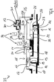
- Fig. 1 shows a gas control device 10, wherein the gas control device 10 according to Fig. 1 a safety valve 11, a main gas valve 12 and a pressure regulator 13 comprises.
- the safety valve 11 and the main gas valve 12 are each formed as spring-loaded diaphragm valves.
- the safety valve 11 designed as a membrane valve comprises a membrane 14, which carries a valve body 15 and is acted upon by a spring element 16.
- the diaphragm 14 of the safety valve 11 delimits a drive chamber 17 of the safety valve 11, in which a servo pressure prevails, from a gas inlet chamber 18, in which a gas inlet pressure prevails.
- the spring force of the spring element 16 and the prevailing in the drive chamber 17 of the safety valve 11 servo pressure close the safety valve 11 against the prevailing in the gas inlet chamber 18 gas inlet pressure, for which purpose the valve body 15 of the safety valve 11 is pressed against a valve seat 19.
- the drive chamber 17 and the gas inlet chamber 18 of the safety valve 11 are coupled via a line 20, wherein in the conduit 20, a diaphragm 21 is integrated.
- the safety valve 11 and the main gas valve 12 is formed as a spring-loaded diaphragm valve, wherein the main gas valve 12 has a diaphragm 22 which carries a valve body 23 which cooperates with a spring element 24.
- the membrane 22 of the main gas valve 11 separates a drive chamber 25 thereof from a gas outlet chamber 26.
- the cooperating with the valve body 23 spring element 24 of the main gas valve 12 and prevailing in the gas outlet 26 gas outlet pressure press the main gas valve 12 in a closed position against the ruling in the drive chamber 25 servo pressure. In the closed state, the valve body 23 of the main gas valve 12 is pressed against a corresponding valve seat 27.
- the drive chamber 25 and the gas discharge chamber 26 of the main gas valve 12 are according to Fig. 1 coupled via a line 28, wherein in the line 28, a diaphragm 29 is connected. Parallel to the aperture 29 engages according Fig. 1 on the line 28 of the pressure regulator 13, via which the outlet pressure of the gas control device can be adjusted.
- the adjustment of the outlet pressure via the gas control device 13 takes place in such a way that the spring force of a spring element 31 of the pressure regulator 13 is adjusted via an adjusting screw 30, whereby the spring element 31 presses a valve body 32 of the pressure regulator 13 against a valve seat 33. Then, when the prevailing in the gas outlet 26 gas outlet pressure is too large, the valve body 32 of the pressure regulator 13 is lifted from the valve seat 33 thereof, so that a pressure compensation can be carried out to limit the outlet pressure.
- Fig. 1 The drive chamber 17 of the safety valve 11 and the drive chamber 25 of the main gas valve 12 are coupled together by two servo valves 34, which are designed as two-way valves. Although technically a single two-way valve would be sufficient as a servo valve 34, are for safety reasons two servo valves 34 available. Both servo valves 34 are always opened or closed only together.
- both servo valves 34 are opened, in which case a pressure equalization between the in the drive chamber 17 of the safety valve 11 and the takes place in the drive chamber 25 of the main gas valve 12 prevailing pressure. In this case, the pressure in the drive chamber 17 of the safety valve 11 decreases, so that the safety valve 11 can be opened against the spring force of the spring element 16 via the gas inlet pressure within the gas inlet chamber 18.
- An inventive gas control device 35 shows Fig. 2 , wherein to avoid unnecessary repetition for the embodiment of Fig. 2 for the same components, the same reference numbers are used in Fig. 1 and will be discussed below only on such details, by which the embodiment of the Fig. 2 from Fig. 1 different.
- Fig. 2 are in contrast to the embodiment of Fig. 1 the servo valves 34 are not formed as two-way valves but as three-way valves with the terminals C (Common), NC (Normally Closed) and NO (Normally Open). Then, when the servo valves 34 are closed, there is a connection between the ports C and NO, respectively. Then, on the other hand, when the servo valves 34 of the embodiment of the Fig. 2 are open, there is a connection between the terminals C and NC. In one between the two servo valves 34 of the Fig. 2 extending line 36 is an aperture 37 integrated. In the embodiment of Fig. 2 deleted in Fig. 1 in the line 28 integrated aperture 29th
- the drive chamber 17 of the diaphragm valve designed as a safety valve 11 and the drive chamber 25 of the diaphragm valve designed as a main valve 12 are coupled together, by opening the servo valves 34, a fast pressure equalization between the two drive chambers 17, 25th can be realized so as to reduce the time required for the gas control valves 10 and 35, respectively, to release a gas flow therethrough.
- the gas control valve 10 and 35 of the Fig. 1 or 2 serves to provide a gas flow to a gas burner, wherein a gas burner in addition to a gas flow and a combustion air flow must be provided. Then, when the gas control device 10 or 35 is used to establish a 1: 1 gas / air control, it has the further advantage that when the gas control device 10 or 35 releases the gas flow to start a gas burner, a short overshoot of the gas outlet pressure, so that a gas / air ratio shifts when starting the gas burner towards a richer gas / air mixture. As a result, the start of such a gas burner can be improved.
Landscapes
- Engineering & Computer Science (AREA)
- Chemical & Material Sciences (AREA)
- Combustion & Propulsion (AREA)
- Mechanical Engineering (AREA)
- General Engineering & Computer Science (AREA)
- Fluid-Driven Valves (AREA)
- Control Of Fluid Pressure (AREA)
Description
- Die Erfindung betrifft ein Gasregelgerät.
- Aus der
DE 198 21 853 C1 ist ein Gasregelgerät für einen Gasbrenner bekannt, welches ein Sicherheitsventil, ein Hauptgasventil und zwei Druckregler umfasst. Nach derDE 198 21 853 C1 ist ein Ausgangssteuerdruck eines ersten Druckreglers durch einen Linearantrieb einstellbar, ein zweiter Druckregler begrenzt den maximal zulässigen Druck des einem Gasbrenner zuzuführenden Gasstroms auf den Druck des dem Brenner zuzuführenden Luftstroms. Bei einer sich verändernden Gasqualität ist der Ausgangssteuerdruck des ersten Druckreglers zur Veränderung des Gasstroms unter Beibehaltung des Luftstroms einstellbar. - Aus der
WO 2008/012849 A1 , derUS 5944257 A und derUS 2004/055651 A1 sind mehrere Gasregelgeräte für ein Gasbrenner bekannt, die jeweils ein Sicherheitsventil, ein Hauptgasventil und ein Druckregler umfassen. - Aus der
WO 2007/060696 A1 ist ein Gasregelgerät nach dem Oberbegriff des Anspruchs 1 bekannt. - Der Erfindung liegt die Aufgabe zu Grunde, ein neuartiges Gasregelgerät zu schaffen. Diese Aufgabe wird durch ein Gasregelgerät mit den Merkmalen des Anspruchs 1 gelöst.
- Beim erfindungsgemäßen Gasregelgerät ist sowohl das Sicherheitsventil als auch das Hauptgasventil jeweils als Membranventil ausgeführt. Die Antriebskammern dieser beiden Membranventile sind unter Zwischenschaltung von Servoventilen miteinander gekoppelt, die als Dreiwegeventil ausgebildet sind. Dann, wenn ein Gasstrom durch das Gasregelgerät bzw. durch das Sicherheitsventil und das Hauptgasventil freigegeben werden soll, werden sämtliche zwischen die Antriebskammern von Sicherheitsventil und Hauptgasventil geschalteten Servoventile geöffnet. Durch Öffnen der Servoventile wird erreicht, dass ein Druckausgleich zwischen beiden Antriebskammern erfolgt, wobei hierbei die Antriebskammer des Hauptgasventils über die Antriebskammer des Sicherheitsventils gefüllt wird. Hierdurch kann ein relativ schnelles Öffnen des Gasregelgeräts trotz Verwendung von Membranventilen realisiert werden. Mit dem erfindungsgemäßen Gasregelgerät können demnach die Öffnungszeiten von Gasregelgeräten mit Membranventilen verkürzt werden.
- Bevorzugte Weiterbildungen der Erfindung ergeben sich aus den Unteransprüchen und der nachfolgenden Beschreibung.
- In der Zeichnung zeigt:
- Fig. 1:
- ein Blockschaltbild eines Gasregelgeräts; und
- Fig. 2:
- ein Blockschaltbild eines erfindungsgemäßen Gasregelgeräts.
-
Fig. 1 zeigt ein Gasregelgerät 10, wobei das Gasregelgerät 10 gemäßFig. 1 ein Sicherheitsventil 11, ein Hauptgasventil 12 und einen Druckregler 13 umfasst. Das Sicherheitsventil 11 und das Hauptgasventil 12 sind jeweils als federbeaufschlagte Membranventile ausgebildet. - Das als Membranventil ausgebildete Sicherheitsventil 11 umfasst eine Membran 14, die einen Ventilkörper 15 trägt und von einem Federelement 16 beaufschlagt ist. Die Membran 14 des Sicherheitsventils 11 grenzt eine Antriebskammer 17 des Sicherheitsventils 11, in welcher ein Servodruck herrscht, von einer Gaseinlasskammer 18, in welcher ein Gaseinlassdruck herrscht, ab.
- Die Federkraft des Federelements 16 sowie der in der Antriebskammer 17 des Sicherheitsventils 11 herrschende Servodruck schließen das Sicherheitsventil 11 entgegen dem in der Gaseinlasskammer 18 herrschenden Gaseinlassdruck, wobei hierzu der Ventilkörper 15 des Sicherheitsventils 11 gegen einen Ventilsitz 19 gedrückt wird. Gemäß
Fig. 1 sind die Antriebskammer 17 und die Gaseinlasskammer 18 des Sicherheitsventils 11 über eine Leitung 20 gekoppelt, wobei in die Leitung 20 eine Blende 21 integriert ist. - Ebenso wie das Sicherheitsventil 11 ist auch das Hauptgasventil 12 als federbeaufschlagtes Membranventil ausgebildet, wobei das Hauptgasventil 12 eine Membran 22 aufweist, die einen Ventilkörper 23 trägt, der mit einem Federelement 24 zusammenwirkt. Die Membran 22 des Hauptgasventils 11 trennt eine Antriebskammer 25 desselben von einer Gasauslasskammer 26 ab. In der Antriebskammer 25 des Hauptgasventils 12 herrscht ein Servodruck und in der Gasauslasskammer 26 ein Gasauslassdruck. Das mit dem Ventilkörper 23 zusammenwirkende Federelement 24 des Hauptgasventils 12 sowie der in der Gasauslasskammer 26 herrschende Gasauslassdruck drücken das Hauptgasventil 12 in eine Schließstellung entgegen dem in der Antriebskammer 25 herrschenden Servodruck. In geschlossenem Zustand wird der Ventilkörper 23 des Hauptgasventils 12 gegen einen entsprechenden Ventilsitz 27 gedrückt.
- Die Antriebskammer 25 und die Gasauslasskammer 26 des Hauptgasventils 12 sind gemäß
Fig. 1 über eine Leitung 28 gekoppelt, wobei in die Leitung 28 eine Blende 29 geschaltet ist. Parallel zur Blende 29 greift gemäßFig. 1 an der Leitung 28 der Druckregler 13 an, über den der Auslassdruck des Gasregelgeräts eingestellt werden kann. Die Einstellung des Auslassdrucks über das Gasregelgerät 13 erfolgt derart, dass über eine Einstellschraube 30 die Federkraft eines Federelements 31 des Druckreglers 13 eingestellt wird, wobei das Federelement 31 einen Ventilkörper 32 des Druckreglers 13 gegen einen Ventilsitz 33 desselben drückt. Dann, wenn der in der Gasauslasskammer 26 herrschende Gasauslassdruck zu groß wird, wird der Ventilkörper 32 des Druckreglers 13 vom Ventilsitz 33 desselben abgehoben, sodass ein Druckausgleich zur Begrenzung des Auslassdrucks erfolgen kann. - Gemäß
Fig. 1 sind die Antriebskammer 17 des Sicherheitsventils 11 und die Antriebskammer 25 des Hauptgasventils 12 durch zwei Servoventile 34 miteinander gekoppelt, die als Zweiwegeventile ausgeführt sind. Obwohl technisch ein einziges Zweiwegeventil als Servoventil 34 ausreichend wäre, sind aus Sicherheitsgründen zwei Servoventile 34 vorhanden. Beide Servoventile 34 werden immer nur gemeinsam geöffnet oder geschlossen. - Soll das in
Fig. 1 dargestellte Gasregelgerät 10 ausgehend von einem Zustand, in welchem dasselbe einen Gasfluss sperrt, in einen Zustand überführt werden, in welcher dasselbe einen Gasfluss freigibt, so werden beide Servoventile 34 geöffnet, wobei dann ein Druckausgleich zwischen dem in der Antriebskammer 17 des Sicherheitsventils 11 und dem in der Antriebskammer 25 des Hauptgasventils 12 herrschenden Druck erfolgt. Hierbei nimmt der Druck in der Antriebskammer 17 des Sicherheitsventils 11 ab, sodass das Sicherheitsventil 11 über den Gaseinlassdruck innerhalb der Gaseinlasskammer 18 entgegen der Federkraft des Federelements 16 geöffnet werden kann. - Hierdurch wird dann Gas von der Antriebskammer 17 des Sicherheitsventils 11 in die Antriebskammer 25 des Hauptgasventils 12 gepumpt bzw. überführt. Hierdurch wird dann innerhalb kurzer Zeit innerhalb der Antriebskammer 25 des Hauptgasventils 12 ein Servodruck aufgebaut, der zum Öffnen des Hauptgasventils 12 entgegen der Federkraft des Federelements 24 und des Gasauslassdrucks in der Gasauslasskammer 26 ausreichend ist.
- Ein erfindungsgemäßes Gasregelgerät 35 zeigt
Fig. 2 , wobei zur Vermeidung unnötiger Wiederholungen für das Ausführungsbeispiel derFig. 2 für gleiche Baugruppen gleiche Bezugsziffern verwendet werden, die inFig. 1 und nachfolgend nur auf solche Details eingegangen wird, durch die sich das Ausführungsbeispiel derFig. 2 vonFig. 1 unterscheidet. - Im Ausführungsbeispiel der
Fig. 2 sind im Unterschied zum Ausführungsbeispiel derFig. 1 die Servoventile 34 nicht als Zweiwegeventile sondern als Dreiwegeventile mit den Anschlüssen C (Common), NC (Normally Closed) und NO (Normally Open) ausgebildet. Dann, wenn die Servoventile 34 geschlossen sind, besteht jeweils eine Verbindung zwischen den Anschlüssen C und NO. Dann hingegen, wenn die Servoventile 34 des Ausführungsbeispiels derFig. 2 geöffnet sind, besteht jeweils eine Verbindung zwischen den Anschlüssen C und NC. In eine zwischen den beiden Servoventilen 34 derFig. 2 verlaufende Leitung 36 ist eine Blende 37 integriert. Im Ausführungsbeispiel derFig. 2 entfällt die inFig. 1 in die Leitung 28 integrierte Blende 29. - Bedingt dadurch, dass bei den Gasregelgeräten 10 bzw. 35 die Antriebskammer 17 des als Membranventil ausgebildeten Sicherheitsventils 11 und die Antriebskammer 25 des als Membranventil ausgebildeten Hauptgasventils 12 miteinander gekoppelt sind, kann durch Öffnen der Servoventile 34 ein schneller Druckausgleich zwischen den beiden Antriebskammern 17, 25 realisiert werden, um so die Zeit zu verringern, die das Gasregelventil 10 bzw. 35 benötigt, um einen Gasdurchfluss durch dasselbe freizugeben.
- Das Gasregelventil 10 bzw. 35 der
Fig. 1 bzw. 2 dient der Bereitstellung eines Gasstroms zu einem Gasbrenner, wobei einem Gasbrenner neben einem Gasstrom auch ein Verbrennungsluftstrom bereitgestellt werden muss. Dann, wenn das Gasregelgerät 10 bzw. 35 zur Etablierung einer 1:1 Gas/LuftRegelung verwendet wird, verfügt dasselbe über den weiteren Vorteil, dass dann, wenn das Gasregelgerät 10 bzw. 35 zum Starten eines Gasbrenners den Gasdurchfluss freigibt, sich ein kurzes Überschießen des Gasauslassdrucks einstellt, sodass sich ein Gas/Luft-Verhältnis beim Starten des Gasbrenners in Richtung auf ein reicheres Gas/Luft-Gemisch verschiebt. Hierdurch kann der Start eines solchen Gasbrenners verbessert werden. -
- 10
- Gasregelgerät
- 11
- Sicherheitsventil
- 12
- Hauptgasventil
- 13
- Druckregler
- 14
- Membran
- 15
- Ventilkörper
- 16
- Federelement
- 17
- Antriebskammer
- 18
- Gaseinlasskammer
- 19
- Ventilsitz
- 20
- Leitung
- 21
- Blende
- 22
- Membran
- 23
- Ventilkörper
- 24
- Federelement
- 25
- Antriebskammer
- 26
- Gasauslasskammer
- 27
- Ventilsitz
- 28
- Leitung
- 29
- Blende
- 30
- Einstellschraube
- 31
- Federelement
- 32
- Ventilkörper
- 33
- Ventilsitz
- 34
- Servoventil
- 35
- Gasregelgerät
- 36
- Leitung
- 37
- Blende
Claims (1)
- Gasregelgerät, mit einem Sicherheitsventil (11), einem Hauptgasventil (12) und einem Druckregler (13), wobei das Sicherheitsventil (11) als ein Membranventil mit einer Gaseinlasskammer (18) und einer Antriebskammer (17) ausgebildet ist, wobei das Hauptgasventil (12) als ein Membranventil mit einer Antriebskammer (25) und einer Gasauslasskammer (26) ausgebildet ist, welches angepasst ist, um bedingt durch die Federkraft eines Federelements (24) und einen in der Gasauslasskammer (26) herrschenden Gasausgangsdruck entgegen einem in der Antriebskammer (25) herrschenden Servodruck zu schließen oder zu öffnen, und wobei die Antriebskammer (17) des Sicherheitsventils (11) und die Antriebskammer (25) des Hauptgasventils (12) unter Zwischenschaltung mindestens eines Servoventils (34) miteinander gekoppelt sind, wobei das oder jedes Servoventil (34) ausgebildet ist, um zum Freigeben eines Gasstroms durch das Sicherheitsventil (11) und das Hauptgasventil (12) zu öffnen und zum Sperren des Gasstroms durch das Sicherheitsventil (11) und das Hauptgasventil (12) zu schließen, und wobei die Antriebskammer (25) des Hauptgasventils (12) und die Gasauslasskammer (26) über eine Leitung (28) gekoppelt sind, in die der Druckregler (31) geschaltet ist, wobei das Sicherheitsventil (11) angepasst ist, um unterstützt durch die Federkraft eines Federelements (16) und unterstützt durch einen in der Antriebskammer (17) herrschenden Servodruck entgegen einem in der Gaseinlasskammer (16) herrschenden Gaseingangsdruck zu schließen und unterstützt durch den in der Gaseinlasskammer (16) herrschenden Gaseingangsdruck entgegen der Federkraft des Federelements (16) und entgegen dem in der Antriebskammer (17) herrschenden Servodruck zu öffnen, dadurch gekennzeichnet, dassdie Gaseinlasskammer (18) und die Antriebskammer (17) des Sicherheitsventils (11) über eine Leitung (20) gekoppelt sind, in die eine Blende (21) integriert ist,zwischen die Leitung (20), über welche die Gaseinlasskammer (18) und die Antriebskammer (17) des Sicherheitsventils (11) gekoppelt sind, und die Leitung (28), über welche die Antriebskammer (25) des Hauptgasventils (12) und die Gasauslasskammer (26) gekoppelt sind, zwei als Dreiwegeventile ausgebildete Servoventile (34) geschaltet sind, nämlich derart, dassein erstes Dreiwegeventil (34) mit seinen Anschlüssen Common und Normally Opened an der Leitung (20) angreift, über welche die Gaseinlasskammer (18) und die Antriebskammer (17) des Sicherheitsventils (11) gekoppelt sind, nämlich parallel zur in diese Leitung (20) integrierten Blende (21),ein zweites Dreiwegeventil (34) mit seinen Anschluß Normally Opened an dem Druckregler (31) und mit seinem Anschluss Common an der Leitung (28) angreift, über welche die Antriebskammer (25) des Hauptgasventils (12) und die Gasauslasskammer (26) gekoppelt sind,die beiden Dreiwegeventile (34) über eine sich zwischen den Anschlüssen Normally Closed derselben erstreckende Leitung (36), in die eine Blende (37) integriert ist, gekoppelt sind.
Applications Claiming Priority (1)
| Application Number | Priority Date | Filing Date | Title |
|---|---|---|---|
| DE102008024843A DE102008024843A1 (de) | 2008-05-23 | 2008-05-23 | Gasregelgerät |
Publications (3)
| Publication Number | Publication Date |
|---|---|
| EP2123979A2 EP2123979A2 (de) | 2009-11-25 |
| EP2123979A3 EP2123979A3 (de) | 2014-08-27 |
| EP2123979B1 true EP2123979B1 (de) | 2019-06-05 |
Family
ID=40990111
Family Applications (1)
| Application Number | Title | Priority Date | Filing Date |
|---|---|---|---|
| EP09005857.9A Active EP2123979B1 (de) | 2008-05-23 | 2009-04-28 | Gasregelgerät |
Country Status (2)
| Country | Link |
|---|---|
| EP (1) | EP2123979B1 (de) |
| DE (1) | DE102008024843A1 (de) |
Cited By (1)
| Publication number | Priority date | Publication date | Assignee | Title |
|---|---|---|---|---|
| WO2022183429A1 (en) | 2021-03-04 | 2022-09-09 | Pittway Sarl | Partially-premixed gas burner appliance |
Citations (2)
| Publication number | Priority date | Publication date | Assignee | Title |
|---|---|---|---|---|
| US20040055651A1 (en) * | 2002-07-18 | 2004-03-25 | Baarda Gerrit Jan | Gas flow control |
| WO2007060696A1 (en) * | 2005-11-23 | 2007-05-31 | Sit La Precisa S.P.A. | Device for controlling the delivery of a combustible gas to a burner apparatus |
Family Cites Families (7)
| Publication number | Priority date | Publication date | Assignee | Title |
|---|---|---|---|---|
| JPH01174819A (ja) * | 1987-12-28 | 1989-07-11 | Yamatake Honeywell Co Ltd | ガス流量制御弁 |
| DE59304310D1 (de) * | 1993-09-16 | 1996-11-28 | Honeywell Bv | Regeleinrichtung für Gasbrenner |
| DE4337703C1 (de) * | 1993-11-05 | 1995-03-23 | Dungs Karl Gmbh & Co | Mehrfachstellgerät mit eingangsseitigem Regler |
| DE4343306A1 (de) * | 1993-12-17 | 1995-06-22 | Gastechnic Prod Vertriebges | Verfahren und Vorrichtung zur Regelung des Druckes in einer Gasleitung |
| US5944257A (en) * | 1996-11-15 | 1999-08-31 | Honeywell Inc. | Bulb-operated modulating gas valve with minimum bypass |
| DE19821853C1 (de) | 1998-05-15 | 1999-07-29 | Honeywell Bv | Regeleinrichtung für Gasbrenner |
| CN101501382B (zh) * | 2006-07-28 | 2012-05-23 | 意大利精密机械技术股份公司 | 用于控制可燃气体到燃烧设备的输送的装置 |
-
2008
- 2008-05-23 DE DE102008024843A patent/DE102008024843A1/de not_active Ceased
-
2009
- 2009-04-28 EP EP09005857.9A patent/EP2123979B1/de active Active
Patent Citations (2)
| Publication number | Priority date | Publication date | Assignee | Title |
|---|---|---|---|---|
| US20040055651A1 (en) * | 2002-07-18 | 2004-03-25 | Baarda Gerrit Jan | Gas flow control |
| WO2007060696A1 (en) * | 2005-11-23 | 2007-05-31 | Sit La Precisa S.P.A. | Device for controlling the delivery of a combustible gas to a burner apparatus |
Cited By (1)
| Publication number | Priority date | Publication date | Assignee | Title |
|---|---|---|---|---|
| WO2022183429A1 (en) | 2021-03-04 | 2022-09-09 | Pittway Sarl | Partially-premixed gas burner appliance |
Also Published As
| Publication number | Publication date |
|---|---|
| EP2123979A2 (de) | 2009-11-25 |
| DE102008024843A1 (de) | 2009-11-26 |
| EP2123979A3 (de) | 2014-08-27 |
Similar Documents
| Publication | Publication Date | Title |
|---|---|---|
| DE60103896T2 (de) | Vorrichtung zum regeln eines gasdurchflusses | |
| DE69727419T2 (de) | Flüssigkeitssteuervorrichtung | |
| DE112011102092B4 (de) | Druckreduziervorrichtung | |
| DE10232647B4 (de) | Regeleinrichtung für Gasbrenner | |
| EP2280179B1 (de) | Wegeventilanordnung | |
| EP2251574B1 (de) | Durchflussregelventil für Heizungs- und Kühlanlagen | |
| DE102009019554B3 (de) | Proportional-Drosselventil | |
| DE1090478B (de) | Druckregler mit einem in einer Nebenleitung liegenden, federbeaufschlagten Steuerdruckregler | |
| DE102011101187B4 (de) | Druckminderer | |
| EP1882882A2 (de) | Volumenstromregler | |
| DE102011056521B4 (de) | Ventilvorrichtung | |
| DE102016002834B4 (de) | Ventil mit einer Überwachungsfunktion | |
| DE4038445C2 (de) | Gasarmatur | |
| EP2123979A2 (de) | Gasregelgerät | |
| EP2718599B1 (de) | Vorrichtung zur handhabung eines flüssigen mediums | |
| EP1382909B1 (de) | Regeleinrichtung für Gasbrenner | |
| DE1500124A1 (de) | Membrangesteuerter Druckregler | |
| DE2655966A1 (de) | Hydraulische regelvorrichtung mit einer stellpumpe | |
| DE102011087511A1 (de) | Druckregelventil | |
| WO2012097888A1 (de) | Ventileinheit für eine kraftstoffpumpe | |
| DE102018126292B3 (de) | Ventil zur energiesparenden, großkapazitiven, direkt wirkenden Präzisionsdruckregelung mit Filterfunktion | |
| DE2719523C3 (de) | Gasventil | |
| DE102015223943B4 (de) | Druckregelvorrichtung | |
| DE102009057029B4 (de) | Druckregelvorrichtung | |
| EP1323975B1 (de) | Vorrichtung zum automatischen Umschalten eines ersten Flüssiggasbehälters auf einen zweiten Flüssiggasbehälter |
Legal Events
| Date | Code | Title | Description |
|---|---|---|---|
| PUAI | Public reference made under article 153(3) epc to a published international application that has entered the european phase |
Free format text: ORIGINAL CODE: 0009012 |
|
| AK | Designated contracting states |
Kind code of ref document: A2 Designated state(s): AT BE BG CH CY CZ DE DK EE ES FI FR GB GR HR HU IE IS IT LI LT LU LV MC MK MT NL NO PL PT RO SE SI SK TR |
|
| RAP1 | Party data changed (applicant data changed or rights of an application transferred) |
Owner name: HONEYWELL TECHNOLOGIES SARL |
|
| PUAL | Search report despatched |
Free format text: ORIGINAL CODE: 0009013 |
|
| AK | Designated contracting states |
Kind code of ref document: A3 Designated state(s): AT BE BG CH CY CZ DE DK EE ES FI FR GB GR HR HU IE IS IT LI LT LU LV MC MK MT NL NO PL PT RO SE SI SK TR |
|
| AX | Request for extension of the european patent |
Extension state: AL BA RS |
|
| RIC1 | Information provided on ipc code assigned before grant |
Ipc: F23N 5/24 20060101ALI20140718BHEP Ipc: F23N 1/00 20060101AFI20140718BHEP Ipc: F23K 5/00 20060101ALI20140718BHEP |
|
| 17P | Request for examination filed |
Effective date: 20150226 |
|
| RBV | Designated contracting states (corrected) |
Designated state(s): AT BE BG CH CY CZ DE DK EE ES FI FR GB GR HR HU IE IS IT LI LT LU LV MC MK MT NL NO PL PT RO SE SI SK TR |
|
| 17Q | First examination report despatched |
Effective date: 20150825 |
|
| STAA | Information on the status of an ep patent application or granted ep patent |
Free format text: STATUS: EXAMINATION IS IN PROGRESS |
|
| GRAP | Despatch of communication of intention to grant a patent |
Free format text: ORIGINAL CODE: EPIDOSNIGR1 |
|
| STAA | Information on the status of an ep patent application or granted ep patent |
Free format text: STATUS: GRANT OF PATENT IS INTENDED |
|
| INTG | Intention to grant announced |
Effective date: 20181024 |
|
| GRAS | Grant fee paid |
Free format text: ORIGINAL CODE: EPIDOSNIGR3 |
|
| GRAJ | Information related to disapproval of communication of intention to grant by the applicant or resumption of examination proceedings by the epo deleted |
Free format text: ORIGINAL CODE: EPIDOSDIGR1 |
|
| GRAL | Information related to payment of fee for publishing/printing deleted |
Free format text: ORIGINAL CODE: EPIDOSDIGR3 |
|
| STAA | Information on the status of an ep patent application or granted ep patent |
Free format text: STATUS: EXAMINATION IS IN PROGRESS |
|
| GRAP | Despatch of communication of intention to grant a patent |
Free format text: ORIGINAL CODE: EPIDOSNIGR1 |
|
| STAA | Information on the status of an ep patent application or granted ep patent |
Free format text: STATUS: GRANT OF PATENT IS INTENDED |
|
| INTC | Intention to grant announced (deleted) | ||
| INTG | Intention to grant announced |
Effective date: 20190321 |
|
| GRAA | (expected) grant |
Free format text: ORIGINAL CODE: 0009210 |
|
| STAA | Information on the status of an ep patent application or granted ep patent |
Free format text: STATUS: THE PATENT HAS BEEN GRANTED |
|
| AK | Designated contracting states |
Kind code of ref document: B1 Designated state(s): AT BE BG CH CY CZ DE DK EE ES FI FR GB GR HR HU IE IS IT LI LT LU LV MC MK MT NL NO PL PT RO SE SI SK TR |
|
| REG | Reference to a national code |
Ref country code: GB Ref legal event code: FG4D Free format text: NOT ENGLISH |
|
| REG | Reference to a national code |
Ref country code: CH Ref legal event code: EP |
|
| REG | Reference to a national code |
Ref country code: AT Ref legal event code: REF Ref document number: 1140385 Country of ref document: AT Kind code of ref document: T Effective date: 20190615 |
|
| REG | Reference to a national code |
Ref country code: DE Ref legal event code: R096 Ref document number: 502009015803 Country of ref document: DE |
|
| REG | Reference to a national code |
Ref country code: IE Ref legal event code: FG4D Free format text: LANGUAGE OF EP DOCUMENT: GERMAN |
|
| REG | Reference to a national code |
Ref country code: NL Ref legal event code: FP |
|
| REG | Reference to a national code |
Ref country code: LT Ref legal event code: MG4D |
|
| PG25 | Lapsed in a contracting state [announced via postgrant information from national office to epo] |
Ref country code: SE Free format text: LAPSE BECAUSE OF FAILURE TO SUBMIT A TRANSLATION OF THE DESCRIPTION OR TO PAY THE FEE WITHIN THE PRESCRIBED TIME-LIMIT Effective date: 20190605 Ref country code: LT Free format text: LAPSE BECAUSE OF FAILURE TO SUBMIT A TRANSLATION OF THE DESCRIPTION OR TO PAY THE FEE WITHIN THE PRESCRIBED TIME-LIMIT Effective date: 20190605 Ref country code: ES Free format text: LAPSE BECAUSE OF FAILURE TO SUBMIT A TRANSLATION OF THE DESCRIPTION OR TO PAY THE FEE WITHIN THE PRESCRIBED TIME-LIMIT Effective date: 20190605 Ref country code: NO Free format text: LAPSE BECAUSE OF FAILURE TO SUBMIT A TRANSLATION OF THE DESCRIPTION OR TO PAY THE FEE WITHIN THE PRESCRIBED TIME-LIMIT Effective date: 20190905 Ref country code: HR Free format text: LAPSE BECAUSE OF FAILURE TO SUBMIT A TRANSLATION OF THE DESCRIPTION OR TO PAY THE FEE WITHIN THE PRESCRIBED TIME-LIMIT Effective date: 20190605 Ref country code: FI Free format text: LAPSE BECAUSE OF FAILURE TO SUBMIT A TRANSLATION OF THE DESCRIPTION OR TO PAY THE FEE WITHIN THE PRESCRIBED TIME-LIMIT Effective date: 20190605 |
|
| PG25 | Lapsed in a contracting state [announced via postgrant information from national office to epo] |
Ref country code: BG Free format text: LAPSE BECAUSE OF FAILURE TO SUBMIT A TRANSLATION OF THE DESCRIPTION OR TO PAY THE FEE WITHIN THE PRESCRIBED TIME-LIMIT Effective date: 20190905 Ref country code: GR Free format text: LAPSE BECAUSE OF FAILURE TO SUBMIT A TRANSLATION OF THE DESCRIPTION OR TO PAY THE FEE WITHIN THE PRESCRIBED TIME-LIMIT Effective date: 20190906 Ref country code: LV Free format text: LAPSE BECAUSE OF FAILURE TO SUBMIT A TRANSLATION OF THE DESCRIPTION OR TO PAY THE FEE WITHIN THE PRESCRIBED TIME-LIMIT Effective date: 20190605 |
|
| PG25 | Lapsed in a contracting state [announced via postgrant information from national office to epo] |
Ref country code: EE Free format text: LAPSE BECAUSE OF FAILURE TO SUBMIT A TRANSLATION OF THE DESCRIPTION OR TO PAY THE FEE WITHIN THE PRESCRIBED TIME-LIMIT Effective date: 20190605 Ref country code: SK Free format text: LAPSE BECAUSE OF FAILURE TO SUBMIT A TRANSLATION OF THE DESCRIPTION OR TO PAY THE FEE WITHIN THE PRESCRIBED TIME-LIMIT Effective date: 20190605 Ref country code: PT Free format text: LAPSE BECAUSE OF FAILURE TO SUBMIT A TRANSLATION OF THE DESCRIPTION OR TO PAY THE FEE WITHIN THE PRESCRIBED TIME-LIMIT Effective date: 20191007 Ref country code: CZ Free format text: LAPSE BECAUSE OF FAILURE TO SUBMIT A TRANSLATION OF THE DESCRIPTION OR TO PAY THE FEE WITHIN THE PRESCRIBED TIME-LIMIT Effective date: 20190605 Ref country code: RO Free format text: LAPSE BECAUSE OF FAILURE TO SUBMIT A TRANSLATION OF THE DESCRIPTION OR TO PAY THE FEE WITHIN THE PRESCRIBED TIME-LIMIT Effective date: 20190605 |
|
| PG25 | Lapsed in a contracting state [announced via postgrant information from national office to epo] |
Ref country code: IS Free format text: LAPSE BECAUSE OF FAILURE TO SUBMIT A TRANSLATION OF THE DESCRIPTION OR TO PAY THE FEE WITHIN THE PRESCRIBED TIME-LIMIT Effective date: 20191005 |
|
| REG | Reference to a national code |
Ref country code: DE Ref legal event code: R097 Ref document number: 502009015803 Country of ref document: DE |
|
| PG25 | Lapsed in a contracting state [announced via postgrant information from national office to epo] |
Ref country code: TR Free format text: LAPSE BECAUSE OF FAILURE TO SUBMIT A TRANSLATION OF THE DESCRIPTION OR TO PAY THE FEE WITHIN THE PRESCRIBED TIME-LIMIT Effective date: 20190605 |
|
| PLBE | No opposition filed within time limit |
Free format text: ORIGINAL CODE: 0009261 |
|
| STAA | Information on the status of an ep patent application or granted ep patent |
Free format text: STATUS: NO OPPOSITION FILED WITHIN TIME LIMIT |
|
| PG25 | Lapsed in a contracting state [announced via postgrant information from national office to epo] |
Ref country code: PL Free format text: LAPSE BECAUSE OF FAILURE TO SUBMIT A TRANSLATION OF THE DESCRIPTION OR TO PAY THE FEE WITHIN THE PRESCRIBED TIME-LIMIT Effective date: 20190605 Ref country code: DK Free format text: LAPSE BECAUSE OF FAILURE TO SUBMIT A TRANSLATION OF THE DESCRIPTION OR TO PAY THE FEE WITHIN THE PRESCRIBED TIME-LIMIT Effective date: 20190605 |
|
| 26N | No opposition filed |
Effective date: 20200306 |
|
| PG25 | Lapsed in a contracting state [announced via postgrant information from national office to epo] |
Ref country code: SI Free format text: LAPSE BECAUSE OF FAILURE TO SUBMIT A TRANSLATION OF THE DESCRIPTION OR TO PAY THE FEE WITHIN THE PRESCRIBED TIME-LIMIT Effective date: 20190605 |
|
| PGFP | Annual fee paid to national office [announced via postgrant information from national office to epo] |
Ref country code: FR Payment date: 20200429 Year of fee payment: 12 |
|
| PGFP | Annual fee paid to national office [announced via postgrant information from national office to epo] |
Ref country code: IT Payment date: 20200424 Year of fee payment: 12 |
|
| PG25 | Lapsed in a contracting state [announced via postgrant information from national office to epo] |
Ref country code: MC Free format text: LAPSE BECAUSE OF FAILURE TO SUBMIT A TRANSLATION OF THE DESCRIPTION OR TO PAY THE FEE WITHIN THE PRESCRIBED TIME-LIMIT Effective date: 20190605 |
|
| REG | Reference to a national code |
Ref country code: CH Ref legal event code: PL |
|
| PG25 | Lapsed in a contracting state [announced via postgrant information from national office to epo] |
Ref country code: CH Free format text: LAPSE BECAUSE OF NON-PAYMENT OF DUE FEES Effective date: 20200430 Ref country code: LU Free format text: LAPSE BECAUSE OF NON-PAYMENT OF DUE FEES Effective date: 20200428 Ref country code: LI Free format text: LAPSE BECAUSE OF NON-PAYMENT OF DUE FEES Effective date: 20200430 |
|
| REG | Reference to a national code |
Ref country code: BE Ref legal event code: MM Effective date: 20200430 |
|
| PG25 | Lapsed in a contracting state [announced via postgrant information from national office to epo] |
Ref country code: BE Free format text: LAPSE BECAUSE OF NON-PAYMENT OF DUE FEES Effective date: 20200430 |
|
| PG25 | Lapsed in a contracting state [announced via postgrant information from national office to epo] |
Ref country code: IE Free format text: LAPSE BECAUSE OF NON-PAYMENT OF DUE FEES Effective date: 20200428 |
|
| REG | Reference to a national code |
Ref country code: AT Ref legal event code: MM01 Ref document number: 1140385 Country of ref document: AT Kind code of ref document: T Effective date: 20200428 |
|
| PG25 | Lapsed in a contracting state [announced via postgrant information from national office to epo] |
Ref country code: AT Free format text: LAPSE BECAUSE OF NON-PAYMENT OF DUE FEES Effective date: 20200428 |
|
| REG | Reference to a national code |
Ref country code: DE Ref legal event code: R081 Ref document number: 502009015803 Country of ref document: DE Owner name: PITTWAY SARL, CH Free format text: FORMER OWNER: HONEYWELL TECHNOLOGIES SARL, ROLLE, CH |
|
| PG25 | Lapsed in a contracting state [announced via postgrant information from national office to epo] |
Ref country code: FR Free format text: LAPSE BECAUSE OF NON-PAYMENT OF DUE FEES Effective date: 20210430 |
|
| PG25 | Lapsed in a contracting state [announced via postgrant information from national office to epo] |
Ref country code: MT Free format text: LAPSE BECAUSE OF FAILURE TO SUBMIT A TRANSLATION OF THE DESCRIPTION OR TO PAY THE FEE WITHIN THE PRESCRIBED TIME-LIMIT Effective date: 20190605 Ref country code: CY Free format text: LAPSE BECAUSE OF FAILURE TO SUBMIT A TRANSLATION OF THE DESCRIPTION OR TO PAY THE FEE WITHIN THE PRESCRIBED TIME-LIMIT Effective date: 20190605 |
|
| REG | Reference to a national code |
Ref country code: GB Ref legal event code: 732E Free format text: REGISTERED BETWEEN 20220505 AND 20220512 |
|
| PG25 | Lapsed in a contracting state [announced via postgrant information from national office to epo] |
Ref country code: MK Free format text: LAPSE BECAUSE OF FAILURE TO SUBMIT A TRANSLATION OF THE DESCRIPTION OR TO PAY THE FEE WITHIN THE PRESCRIBED TIME-LIMIT Effective date: 20190605 |
|
| REG | Reference to a national code |
Ref country code: NL Ref legal event code: PD Owner name: PITTWAY SARL; CH Free format text: DETAILS ASSIGNMENT: CHANGE OF OWNER(S), ASSIGNMENT; FORMER OWNER NAME: HONEYWELL TECHNOLOGIES SARL Effective date: 20221223 |
|
| PG25 | Lapsed in a contracting state [announced via postgrant information from national office to epo] |
Ref country code: IT Free format text: LAPSE BECAUSE OF NON-PAYMENT OF DUE FEES Effective date: 20200428 |
|
| P01 | Opt-out of the competence of the unified patent court (upc) registered |
Effective date: 20230827 |
|
| PGFP | Annual fee paid to national office [announced via postgrant information from national office to epo] |
Ref country code: NL Payment date: 20250424 Year of fee payment: 17 |
|
| PGFP | Annual fee paid to national office [announced via postgrant information from national office to epo] |
Ref country code: DE Payment date: 20250528 Year of fee payment: 17 |
|
| PGFP | Annual fee paid to national office [announced via postgrant information from national office to epo] |
Ref country code: GB Payment date: 20250422 Year of fee payment: 17 |
|
| PG25 | Lapsed in a contracting state [announced via postgrant information from national office to epo] |
Ref country code: IT Free format text: LAPSE BECAUSE OF NON-PAYMENT OF DUE FEES Effective date: 20210428 |