EP2122327B1 - Method for improving absorbance detection of a droplet - Google Patents
Method for improving absorbance detection of a droplet Download PDFInfo
- Publication number
- EP2122327B1 EP2122327B1 EP08743832.1A EP08743832A EP2122327B1 EP 2122327 B1 EP2122327 B1 EP 2122327B1 EP 08743832 A EP08743832 A EP 08743832A EP 2122327 B1 EP2122327 B1 EP 2122327B1
- Authority
- EP
- European Patent Office
- Prior art keywords
- droplet
- light
- path
- sensor
- light source
- Prior art date
- Legal status (The legal status is an assumption and is not a legal conclusion. Google has not performed a legal analysis and makes no representation as to the accuracy of the status listed.)
- Not-in-force
Links
Images


Classifications
-
- G—PHYSICS
- G01—MEASURING; TESTING
- G01N—INVESTIGATING OR ANALYSING MATERIALS BY DETERMINING THEIR CHEMICAL OR PHYSICAL PROPERTIES
- G01N21/00—Investigating or analysing materials by the use of optical means, i.e. using sub-millimetre waves, infrared, visible or ultraviolet light
- G01N21/01—Arrangements or apparatus for facilitating the optical investigation
- G01N21/03—Cuvette constructions
- G01N21/0303—Optical path conditioning in cuvettes, e.g. windows; adapted optical elements or systems; path modifying or adjustment
-
- G—PHYSICS
- G01—MEASURING; TESTING
- G01N—INVESTIGATING OR ANALYSING MATERIALS BY DETERMINING THEIR CHEMICAL OR PHYSICAL PROPERTIES
- G01N21/00—Investigating or analysing materials by the use of optical means, i.e. using sub-millimetre waves, infrared, visible or ultraviolet light
- G01N21/01—Arrangements or apparatus for facilitating the optical investigation
- G01N21/03—Cuvette constructions
- G01N2021/0346—Capillary cells; Microcells
- G01N2021/035—Supports for sample drops
-
- G—PHYSICS
- G01—MEASURING; TESTING
- G01N—INVESTIGATING OR ANALYSING MATERIALS BY DETERMINING THEIR CHEMICAL OR PHYSICAL PROPERTIES
- G01N21/00—Investigating or analysing materials by the use of optical means, i.e. using sub-millimetre waves, infrared, visible or ultraviolet light
- G01N21/01—Arrangements or apparatus for facilitating the optical investigation
- G01N21/03—Cuvette constructions
- G01N2021/036—Cuvette constructions transformable, modifiable
-
- G—PHYSICS
- G01—MEASURING; TESTING
- G01N—INVESTIGATING OR ANALYSING MATERIALS BY DETERMINING THEIR CHEMICAL OR PHYSICAL PROPERTIES
- G01N21/00—Investigating or analysing materials by the use of optical means, i.e. using sub-millimetre waves, infrared, visible or ultraviolet light
- G01N21/01—Arrangements or apparatus for facilitating the optical investigation
- G01N21/03—Cuvette constructions
- G01N21/031—Multipass arrangements
-
- G—PHYSICS
- G01—MEASURING; TESTING
- G01N—INVESTIGATING OR ANALYSING MATERIALS BY DETERMINING THEIR CHEMICAL OR PHYSICAL PROPERTIES
- G01N2201/00—Features of devices classified in G01N21/00
- G01N2201/08—Optical fibres; light guides
Definitions
- the invention relates to a method for improving absorbance detection of a droplet on the droplet actuator.
- Droplet actuators are used to conduct a wide variety of droplet operations.
- a droplet actuator typically includes a substrate associated with electrodes configured for conducting droplet operations on a droplet operations surface thereof and may also include a second substrate arranged in a generally parallel fashion in relation to the droplet operations surface to form a gap in which droplet operations are effected.
- the gap is typically filled with a filler fluid that is immiscible with the fluid that is to be subjected to droplet operations on the droplet actuator.
- it is useful to detect absorbance of a droplet or other fluid, and in some cases, the fluid is located on a droplet actuator.
- US2006/039823 A1 discloses a chemical analysis apparatus for analysing small quantities of substances e.g. biological samples such as sera in which droplets are transported along electrode rows so that droplets containing the samples and the reagents are located between plate members facing each other as in Fig. 3 .
- the samples are e.g. provided from a sample-dispensing probe 105.
- irradiation is performed such that light enters at an angle with respect to each substrate from a light source 119 such as an LED, so as to cause light to reflect a plurality of times between the mixing electrode row 118 on the upper substrate 201 and the counter electrode 211 on the lower substrate 202.
- the light path is made longer so as to prevent analysis accuracy from being lowered.
- the light source 119 and a light receiving section 120 can be provided on the same upper surface side of each substrate for analysis, enabling facilitation of optical alignment.
- the larger the droplet volume the longer the light path.
- the sample droplet in Fig. 5 is surrounded by inert oil 207 filling the gaps between droplets.
- the invention relates to a method for determining the absorbance of a droplet.
- the invention may make use of a droplet actuator.
- the droplet actuator may include two substrates separated to form a gap. A droplet positioned in the gap will have a droplet height established by surfaces of the two substrates.
- a light source may be arranged to transmit light through the droplet.
- a sensor may be arranged to sense light emitted from the droplet. In this manner, a light path is established from the light source, through the droplet, to the sensor.
- a method of the invention involves directing light from the light source through the droplet and to the sensor sensing the light energy at the sensor: and determining from the sensed light energy the absorbance of the droplet.
- the light path through the droplet is greater than the droplet height.
- the light path may, for example, be substantially parallel with the surfaces of the substrates.
- the light path through the droplet may, in some cases, be substantially perpendicular to the droplet height. In other cases, the light path through the droplet may be established at an angle that is substantially acute with respect to one of the surfaces establishing the droplet height.
- the light source and the sensor are offset from a central vertical axis of the droplet.
- the light source and the sensor may be arranged on the same or opposite sides of a droplet actuator.
- the light path through the droplet is at least 2, 3, 4, 5, 6, 7, 8, 9, 10 or more times greater than the droplet height.
- one or more of the substrates comprises a recessed region such that a droplet located in the recessed region has a greater droplet height than a droplet located in a region that is not so recessed.
- one or more of the substrates comprises an aperture arranged such that a droplet in contact with the aperture will enter the aperture, thereby providing the droplet with a greater droplet height than a droplet located in the gap.
- Droplet operations may be used to elongate or increase the height of the droplet along the direction of the light path.
- the droplet operations may, in some cases, be mediated by electrodes.
- the droplet may be positioned within an aperture of a substrate, thereby increasing the droplet height or length.
- One or more electrodes may be provided in one or more of the substrates and configured to conduct one or more droplet operations elongating the droplet in a manner which increases the distance of the light path through the droplet.
- Diffractive material may be used to direct light from the light source through the droplet and to the sensor.
- the light path may be directed through the diffractive material prior to or after the droplet.
- a prism or waveguide may be provided as the diffractive material.
- the light path may reflect off of a surface of one or both of the two substrates.
- one or more of the substrates may include a material having a lower refractive index than the droplet.
- the droplets subjected to detection may include beads.
- the optical property of the droplet may be indicative of an optical property of the beads.
- the droplet may include biological cells, and the optical property of the droplet may be indicative of an optical property of the biological cells.
- the droplet subjected to detection may be partially or completely surrounded by filler fluid.
- the filler fluid may, in some cases, have different light refractive characteristics than light refractive characteristics of the droplet.
- the filler fluid may be selected such that certain wavelengths of light incident upon the filler fluid do not reach the sensor.
- light in a wavelength of interest may pass through the droplet to the sensor but may not pass through the filler fluid to the sensor.
- Activate with reference to one or more electrodes means effecting a change in the electrical state of the one or more electrodes which results in a droplet operation.
- Bead with respect to beads on a droplet actuator, means any bead or particle that is capable of interacting with a droplet on or in proximity with a droplet actuator. Beads may be any of a wide variety of shapes, such as spherical, generally spherical, egg shaped, disc shaped, cubical and other three dimensional shapes. The bead may, for example, be capable of being transported in a droplet on a droplet actuator or otherwise configured with respect to a droplet actuator in a manner which permits a droplet on the droplet actuator to be brought into contact with the bead, on the droplet actuator and/or off the droplet actuator.
- Beads may be manufactured using a wide variety of materials, including for example, resins, and polymers.
- the beads may be any suitable size, including for example, microbeads, microparticles, nanobeads and nanoparticles.
- beads are magnetically responsive; in other cases beads are not significantly magnetically responsive.
- the magnetically responsive material may constitute substantially all of a bead or one component only of a bead. The remainder of the bead may include, among other things, polymeric material, coatings, and moieties which permit attachment of an assay reagent. Examples of suitable magnetically responsive beads are described in U.S. Patent Publication No.
- the beads may include one or more populations of biological cells adhered thereto.
- the biological cells are a substantially pure population.
- the biological cells include different cell populations, e.g., cell populations which interact with one another.
- Droplet means a volume of liquid on a droplet actuator that is at least partially bounded by filler fluid.
- a droplet may be completely surrounded by filler fluid or may be bounded by filler fluid and one or more surfaces of the droplet actuator.
- Droplets may take a wide variety of shapes; nonlimiting examples include generally disc shaped, slug shaped, truncated sphere, ellipsoid, spherical, partially compressed sphere, hemispherical, ovoid, cylindrical, and various shapes formed during droplet operations, such as merging or splitting or formed as a result of contact of such shapes with one or more surfaces of a droplet actuator.
- Droplet operation means any manipulation of a droplet on a droplet actuator.
- a droplet operation may, for example, include: loading a droplet into the droplet actuator; dispensing one or more droplets from a source droplet; splitting, separating or dividing a droplet into two or more droplets: transporting a droplet from one location to another in any direction; merging or combining two or more droplets into a single droplet; diluting a droplet; mixing a droplet; agitating a droplet; deforming a droplet; retaining a droplet in position: incubating a droplet; heating a droplet; vaporizing a droplet; cooling a droplet; disposing of a droplet; transporting a droplet out of a droplet actuator; other droplet operations described herein; and/or any combination of the foregoing.
- any combination of droplet operations sufficient to result in the combination of the two or more droplets into one droplet may be used.
- “merging droplet A with droplet B” can be achieved by transporting droplet A into contact with a stationary droplet B, transporting droplet B into contact with a stationary droplet A, or transporting droplets A and B into contact with each other.
- splitting is not intended to imply any particular outcome with respect to size of the resulting droplets (i.e., the size of the resulting droplets can be the same or different) or number of resulting droplets (the number of resulting droplets may be 2, 3, 4, 5 or more).
- mixing refers to droplet operations which result in more homogenous distribution of one or more components within a droplet. Examples of “loading” droplet operations include microdialysis loading, pressure assisted loading, robotic loading, passive loading, and pipette loading.
- top and bottom are used throughout the description with reference to the top and bottom substrates of the droplet actuator for convenience only, since the droplet actuator is functional regardless of its position in space.
- a given component such as a layer, region or substrate
- that given component can be directly on the other component or, alternatively, intervening components (for example, one or more coatings, layers, intertayers, electrodes or contacts) can also be present.
- intervening components for example, one or more coatings, layers, intertayers, electrodes or contacts
- the terms “disposed on” and “formed on” are used interchangeably to describe how a given component is positioned or situated in relation to another component.
- the terms “disposed on” and “formed on” are not intended to introduce any limitations relating to particular methods of material transport, deposition, or fabrication.
- a liquid in any form e.g., a droplet or a continuous body, whether moving or stationary
- a liquid in any form e.g., a droplet or a continuous body, whether moving or stationary
- an electrode, array, matrix or surface such liquid could be either in direct contact with the electrode/array/matrix/surface, or could be in contact with one or more layers or films that are interposed between the liquid and the electrode/array/matrix/surface.
- a droplet When a droplet is described as being “on” or “loaded on” a droplet actuator, it should be understood that the droplet is arranged on the droplet actuator in a manner which facilitates using the droplet actuator to conduct one or more droplet operations on the droplet, the droplet is arranged on the droplet actuator in a manner which facilitates sensing of a property of or a signal from the droplet, and/or the droplet has been subjected to a droplet operation on the droplet actuator.
- Droplet actuators may be coupled to and/or configured with a light source and a detector. Light from the light source may pass through a droplet on the droplet actuator to the detector. Characteristics of the light energy emitted from the droplet may be detected and analyzed. For example, one can calculate the concentration of a solution based on the incident light and the intensity of light detected using Beer's law. However, for path-lengths of less than 1 cm, the effect of minor inaccuracies in the measurement of the detected light are magnified. Sensitivity is very important, and it is desirable for the change in signal to be several times larger than the noise in the solution. In droplet actuators, path-lengths of less than 1 cm are frequently observed under standard assay conditions and device placement.
- the droplet actuator size may be hundreds of microns. Accordingly, the disclosure provides a device, device configuration, and/or method, in which the path-length is increased relative to the height of the droplet on the droplet actuator. The disclosure provides a droplet actuator configured for improved absorbance detection of a droplet or fluid on the droplet actuator.
- the droplet In a standard design, the droplet is positioned between the light source and a detector, where the light source is at the bottom, the sample is in the middle, and the detector is on top.
- the path-length in this standard design would be hundreds of microns, which, as described above is not optimal.
- Figures 1 - 11 illustrate improvements of the disclosure on the standard design.
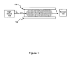
- Figure 1 illustrates an absorbance detection device or configuration of the disclosure
- Figure 1 shows top substrate 100 separated from bottom substrate 102 by gap 105.
- Gap 105 contains droplet 101.
- Gap 105 may typically have a gap height ranging from about 100 to about 200 ⁇ m. In other cases, the gap height can range from a few microns to several millimeters.
- Droplet 101 has a horizontal diameter, which may typically range from about 500 to about 1000 ⁇ m. In other cases, the horizontal diameter can range from a few microns to several millimeters.
- the path-length of light from light source 103 as it passes through droplet 101 to detector or sensor 104 is increased relative to the gap height.
- the horizontal arrangement of source 103 and detector 104 illustrated in this figure may result in about a 4.5X or 5X increase in path-length for a single droplet relative to a typical vertical configuration in a typical droplet actuator.
- the horizontal droplet length may in some cases be extended, for example, by forcing droplet 101 into a narrower gap and/or by forcing droplet 101 between lateral barriers, and/or by forcing droplet 101 into a capillary.
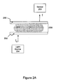
- Figure 2A illustrates an absorbance detection device or configuration of the disclosure.
- Top substrate 200 is separated from bottom substrate 202 by gap 209.
- Gap 209 may contain droplet 201.
- Light source 204 and detector or sensor 203 are on opposite sides of the droplet actuator. They are also off-set, i.e., they are not on the same vertical axis. In some cases, they may be on opposite sides of the same vertical axis which passes vertically through the center of droplet 201. In some examples, they are offset by a distance which substantially maximizes the path-length of light through droplet 201. Light is thus transmitted in a generally diagonal direction through droplet 201.
- the diagonal path-length is a greater path-length as compared to the height.
- the path-length of light through the droplet may in some cases range from about 500 to about 1000 ⁇ m.
- Figure 2B illustrates an example of Figure 2A .
- light sources are much larger than droplet size.
- An aperture or a mask may be provided to help ensure that all of the light from source 204 that is sensed by the sensor 203 is transmitted through droplet 201. In other words, this approach minimizes or substantially eliminates light from light source 204 reaching sensor 203 by a path that excludes droplet 201.
- the source 204 may be masked, the substrates of the droplet actuator may be masked, or a fiber optic with a small diameter may be used to direct light to the droplet.
- the masking is provided by electrode 206. Opening 205 is provided in electrode 206. Opening 205 directs light through droplet 201.
- the top portion of Figure 2B represents a top view of electrode 206 showing opening 205. Opening 205 may, in some cases, be located at a position which is near an outer edge of droplet 201.
- the lower portion of Figure 2B represents a side view of the droplet actuator. Light from light source 204 is transmitted through opening 205 in electrode 206, through the droplet, to the sensor.
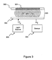
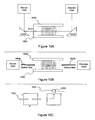
- Top surface 300 may include reflective region 301 or in some cases, the entire top surface may be reflective.
- Light source 303 and detector or sensor 304 are located on the same side of droplet 301. They may in some cases be located in substantially the same plane on the same side of droplet 301.
- Top substrate 300 includes a reflective region 301 and is separated from bottom substrate 302 by a gap 305. Alternatively, reflective region 301 may be the bottom surface. Gap 305 may contain droplet 301.
- Light source 303 is on the same side of droplet 301 as sensor 304 and may in some cases be in substantially the same plane as sensor 304.
- Reflective region 301 be rendered reflective by using reflective materials and/or coating with reflective materials, such as aluminum, gold, reflective chrome or any other reflective coating.
- the light transmitted by light source 303 is reflected off of reflective region 301, effectively doubling the path length of light through the droplet.
- Reflective region 301 may be substantially 100% reflective or may reflect only selected bandwidths of light.
- FIG. 4A illustrates an absorbance detection device or configuration of the disclosure.
- Both top substrate 400 and bottom substrate 402 include reflective regions 410 and 412, respectively.
- Light source 403 and detector or sensor 404 are located on the same side of droplet 401.
- Reflective surface 412 leaves sufficient opening for light to enter the droplet at one region thereof and leave the droplet at another region thereof. Preferably the distance between entry and exit points is substantially maximized.
- Reflective surface 410 substantially covers the droplet in order to minimize light loss via the top substrate.
- Light transmitted from light source 403 enters droplet 401 through bottom substrate 402. The light is reflected off of reflective surfaces 410 and 412 through droplet 401, and exits droplet 401 to sensor 404.
- the top and bottom substrates may be reversed in this example.
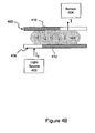
- Figure 4B illustrates an absorbance detection device or configuration of the disclosure.
- Both top substrate 405 and bottom substrate 406 include reflective regions 410 and 412, respectively.
- Light source 403 and sensor 404 are located on opposite side of droplet 401.
- Reflective surface 412 leaves sufficient opening for light to enter the droplet at one region.
- Reflective surface 410 leaves sufficient opening for light to enter the droplet at one region.
- the distance between entry and exit points is substantially maximized.
- Light transmitted from light source 403 enters droplet 401 through bottom substrate 406. The light is reflected off of reflective surfaces 410 and 412 through droplet 401 and exits droplet 401 through top substrate 405 to sensor 404.
- the top and bottom substrates may be reversed in this example.
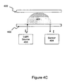
- Figure 4C illustrates an absorbance detection device or configuration of the disclosure.
- Bottom surface 402 is at least partially transmissive and/or includes at least partially transmissive regions for entry and exit of light to and from droplet 401.
- Top surface 400 may or may not be transmissive. In some examples, such as the one shown, the distance between top substrate 400 and bottom substrate 402 is selected relative to the droplet and electrode (if any) size and properties to cause droplet 401 to take on a substantial dome or semi-spherical shape.
- TIR total internal reflection
- the refractive index of droplet must be greater than that of the surrounding medium for TIR to occur and result in an increased path-length.
- Figure 4C illustrates an example in which droplet shape is symmetrically altered to support TIR
- droplet may be altered asymmetrically.
- one side of droplet may have an acute contact angle (wetting) while the other side is obtuse (nonwetting).
- the source 403 and detector 404 may be orthogonal.
- this light source may be located on a bottom side of droplet, while sensor is located on the opposite side of droplet.
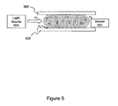
- Figure 5 illustrates an absorbance detection device or configuration of the disclosure.
- light transmitted from light source 503 passes through droplet 501 to sensor 504.
- Droplet 501 which has a higher refractive index as compared to the inner surface of top substrate 500 and bottom substrate 502 and/or as compared to the filler fluid.
- Droplet 501 operates as a wave guide utilizing the total internal reflection phenomenon, resulting in a greatly increased path-length.
- the refractive index n2 of droplet 501 is sufficiently greater than the refractive index of top and bottom surfaces n1, and the refractive index of the filler fluid n3 to cause the droplet to function as a waveguide. In other words, n2 > ⁇ n3. n1 ⁇ .
- the length of droplet 501 is greatly increased (e.g., to 10 or 20 droplets), and light transmitted from light source 503 passes through droplet 501 which functions as a wave guide transmitting light to sensor 504.
- multiple droplets such as about 1 to about 30 droplets or about 10 to about 20 droplets, may be added to droplet to change the dynamic range of the detector. If a droplet is too dense or if the absorption needs to be decreased, for example, diluent, buffer or reaction mixture may be added using droplet operations to merge the droplet with one or more additional droplets. The addition of droplets may help obtain a discernable signal. The addition of droplets may occur in real time. For example, if in real time output is measured, and it is determined that the addition of a droplet or droplets would improve the output, then more droplets may be added to achieve sufficient output. On the other hand, if the absorption in the droplet needs to be increased, then the production of absorbing species may be concentrated on the droplet actuator into a small number of droplets using methods for pre-concentration.
- Figure 5 shows a non-limiting example in which light source 503 is lateral to droplet 501, the light could be transmitted from the top, bottom or at an angle. If the light is transmitted from the top or bottom, the angle should be below the critical angle to enable the light to go through wave guiding.
- top substrate 500 or bottom substrate 502 may be made of a low refractive material.
- Teflon and Cytop are examples of suitable materials with a low refractive index useful in the disclosure.
- a filler fluid may also be selected having a refractive index lower than that of droplet.
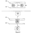
- Figure 6 illustrates an absorbance detection device or configuration of the disclosure.
- the path-length of light from light source 607 as it passes through droplet AB to detector or sensor 608 is increased vertically due to the presence of recesses or gaps of different heights in the droplet actuator.
- the droplet actuator has a first gap 604 of a certain height (such as about 100 ⁇ m), and a second gap 605 of a greater height (such as about 500 ⁇ m).
- Droplets A and B are first positioned in the gap 604 of a shorter height.
- One or more droplets having sufficient volume may be transported into the gap 605.
- droplets A and B are merged using droplet operations in the gap 605 to yield droplet AB having an increased droplet height relative to the starting droplets.
- Source 607 and detector 608 are located below and above the gap 605 of greater height.
- the path-length of light from light source 607 as it passes through droplet AB in the gap 605 of greater height to sensor 608 is increased vertically.
- Figure 7 illustrates an absorbance detection device or configuration of the disclosure.
- the path-length of light from light source 705 as it passes through droplet 703, in the opening 706, to detector or sensor 704, is increased vertically relative to the droplet height as established by the height of gap 709.
- the top portion of Figure 7 shows the side view of the example illustrating top substrate 700 separated from the bottom substrate 702 by gap 709.
- Gap 709 may contain droplet 701.
- Top substrate 700 includes an opening 706. Opening 706 may have a volume capacity similar to or larger than the size of droplet 701. Opening 706 may be a capillary.
- Bottom substrate 702 may include a transparent region which is underneath the opening 706 in line with the light path from light source 705 to sensor 704.
- FIG. 7 shows a top view of the example, illustrating opening 706 in top substrate 700. While opening 706 is illustrated here in the top substrate, it should be noted that it may be in the bottom substrate or even in a side wall or other structure of the droplet actuator.
- a droplet 701 is placed in droplet actuator.
- Droplet 701 can be positioned at opening 706 and made to enter 706, e.g., by capillary action, by electrostatic, mechanical or other means.
- Opening 706 has a diameter selected in relation to the height of gap 709 and size of droplet 701 to cause droplet 701 to passively enter opening 706. If D in the figure is smaller than H, droplet 704 will passively enter opening 706 (note that the figure is not drawn to scale).
- Light from light source 705 is transmitted through droplet 703 in opening 706 to sensor 704.
- FIG 8 illustrates an absorbance detection device or configuration of the disclosure (top view).
- a transparent region 801 is provided in the substrate 800 so that substantially all of the light that reaches the sensor (not shown) is transmitted through droplet 802.
- Electrode 803 is made using an opaque material, such as aluminum, chrome, copper or other materials used for forming electrodes. Alternatively, an opaque material may be coated onto the electrode or onto the substrate with which the electrode is associated. The opaque material may be on the same surface as electrode 803, or below the droplet actuator, for example. Further, as illustrated, the opaque region may extend to regions of the substrate beyond electrode 803 as needed to fully block light not passing through transparent region 801.
- Transparent region 801 may be sized to transmit the desired amount of light from a light source (not shown).
- Transparent region 801 may include one or more transparent regions, and may be an array of transparent regions. Transparent region 801 may contain a diffraction grating or other optical element. The electrode itself may be a diffraction grating. Diffractive optics, or other optics such as lenses, may be patterned in the metal or first conductive layer in transparent region 801. Transparent region 801 may be semi-transparent or may include or be comprised of a filter which transmits a desired set of wavelengths. Similarly, the opaque regions may be semi-opaque or may include a filter which excludes a desired set of wavelengths. Such diffractive optics can also be helpful for other forms of optical detection such as in fluorescence and luminescence where optical filters can also be constructed.
- FIG. 9A illustrates an absorbance detection device or configuration of the disclosure.
- a single droplet 901 is elongated to provide an elongated light path for detection.
- a single droplet can be elongated by addition of multiple droplets or by reducing the size of the unit electrode.
- each electrode 910 is comprised of multiple smaller electrodes 911. By activating these smaller electrodes in a sequence, droplet 901 can be elongated to form elongated droplet 902.
- the path-length of light from light source 903 as it passes through droplet 902 to detector or sensor 904 is thereby increased.
- Different electrodes can be activated to elongate droplet laterally.
- the source 903 and detector 904 are, in this example, located laterally with respect to droplet.
- a similar configuration can be arranged vertically to elongate a droplet in a vertical direction, or in any other spatial orientation.
- Figure 9B illustrates an absorbance detection device or configuration of the disclosure.
- droplet 905 is elongated in the presence of electric field to form an elongated droplet 907.
- the path-length of light from light source 903 as it passes through droplet 907 to detector or sensor 904 is thereby increased.
- Light source 903 and sensor 904 are placed horizontally along the direction of elongation of droplet.
- the elongated or wire-shaped electrode 906 supplies the field that causes the droplet to generally conform to the shape of electrode 906, thereby forming the elongated droplet 907.
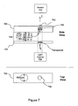
- Figure 10A illustrates an absorbance detection device or configuration of the disclosure.
- light source 1005 and detector or sensor 1006 are on the same side of the droplet actuator, and may be in substantially the same plane, but not in the same plane as droplet 1003.
- Top substrate 1000 is separated from bottom substrate 1002 by gap 1010.
- Droplet 1003 may be present in gap 1010.
- Light from light source 1005 is redirected by prism 1001a through droplet 1003.
- Light from droplet 1003 is redirected by prism 1001b to sensor 1006. Any optical element used to redirect light, e.g., mirrors, may be used in this configuration.
- the light source and sensor may be located in any spatial orientation relative to the droplet, so long as the optical elements used to redirect light cause the light to be directed substantially in a direction through the droplet which provides a lengthened light path relative to other possible directions through the droplet by which light could be directed.
- Figure 10B illustrates an absorbance detection device or configuration of the disclosure.
- light from light source 1005 is transmitted to droplet 1003 using an optical fiber 1004a and from droplet 1003 to detector or sensor 1006 using optical fiber 1004b.
- a droplet actuator may be constructed which has an extension into which droplet 1003 is positioned.
- the optical fibers may be configured on either side of the extension feature.
- Figure 11 illustrates an absorbance detection device or configuration of the invention.
- filler fluid 1105 includes dyes or additives that absorb light of interest.
- Light from light source 1104 directs light through droplet 1102 to detector or sensor 1100. Some portion of all of the light that does not go through droplet 1102 is absorbed or reflected by filler fluid 1105.
- This embodiment is particularly suitable for configurations in which light source 1104 and/or detector 1100 is greater in size than droplet 1102.
- the area surrounding droplet 1102 can be masked with the filler fluid 1105.
- the filler fluid 1105 may contain a dye or an inverse color filter, the filler fluid 1105 may be opaque, and/or the filler fluid 1105 may have a refractive index to deflect the light away from sensor 1100 and not through droplet 1102.
- the filler fluid may be an oil, such as a silicone oil, doped with oil-soluble particles to scatter the light from a light-emitting droplet (e.g., fluorescing droplet) so that the droplet's light does not make its way into another droplet.
- a light-emitting droplet e.g., fluorescing droplet
- dyes may be used in this embodiment.
- Keystone Aniline makes oil soluble dyes (also fluorescent dyes) that could be used.
- Black dye such as carbon black, may be used.
- Colored silicone oil is also available from Gelest, e.g., DMS-T21BLU and DMS-T21RED.
- Suitable dyes include: Sandoplast Red BB, magenta, sudan I, sudan II, sudan III, and sudan IV, oil red O, and Nile red.
- the oil soluble dye also serves as a surfactant.
- any monochromatic light source may be used with a filter.
- LEDs which are tuned to the wavelength of the measured dye in droplet are useful.
- Lasers may be useful.
- Detectors or sensors may be silicon, photodiode, multiple photodiodes, photodiode arrays, single sensors, or additional CCD, avalanche photodiodes, PMT (photo multiplier tube), photon counting PMTs or any other low noise detectors, for example. Examples of light sources, detectors and configurations are provided in International Patent Application No. PCT/US2006/47486 , entitled “Droplet-Based Biochemistry," filed on December 11, 2006. It will be appreciated that while the disclosure is focused on detection of absorbance of a droplet, many of the configurations will also be suitable for enhancing detection of fluorescence and/or luminescence of a droplet.
- Patents 6,773,566 entitled “Electrostatic Actuators for Microfluidics and Methods for Using Same,” issued on August 10, 2004 and 6,565,727 , entitled “Actuators for Microfluidics Without Moving Parts,” issued on January 24, 2000, both to Shenderov et al.; and Pollack et al., International Patent Application No. PCT/US2006/47486 , entitled “Droplet-Based Biochemistry,” filed on December 11, 2006.
- Gap heights are preferably from 10's ⁇ m to 1's cm and more preferably from 100's ⁇ m to 10's mm and most preferably from 100's ⁇ m to 1's mm.
- Electrode dimensions preferably in 10's ⁇ m, more preferably in 100's ⁇ m, most preferably in the range of 10 mm to 1000's ⁇ m.
- the fluid includes a biological sample, such as whole blood, lymphatic fluid, serum, plasma sweat, tear, saliva, sputum, cerebrospinal fluid, amniotic fluid, seminal fluid, vaginal excretion, serous fluid, synovial fluid, pericardial fluid, peritoneal fluid, pleural fluid, transudates, exudates, cystic fluid, bile, urine, gastric fluid, intestinal fluid, fecal samples, fluidized tissues, fluidized organisms, biological swabs and biological washes.
- a biological sample such as whole blood, lymphatic fluid, serum, plasma sweat, tear, saliva, sputum, cerebrospinal fluid, amniotic fluid, seminal fluid, vaginal excretion, serous fluid, synovial fluid, pericardial fluid, peritoneal fluid, pleural fluid, transudates, exudates, cystic fluid, bile, urine, gastric fluid, intestinal fluid, fecal samples, fluidized tissues, fluidized
- the gap will typically be filled with a filler fluid.
- the filler fluid may, for example, be a low-viscosity oil, such as silicone oil; or a gas, such as air or an inert gas.
- a low-viscosity oil such as silicone oil
- a gas such as air or an inert gas.
- Other examples of filler fluids are provided in International Patent Application No. PCT/US2006/47486 , entitled “Droplet-Based Biochemistry,” filed on December 11, 2006.
Landscapes
- Physics & Mathematics (AREA)
- Health & Medical Sciences (AREA)
- Life Sciences & Earth Sciences (AREA)
- Chemical & Material Sciences (AREA)
- Analytical Chemistry (AREA)
- Biochemistry (AREA)
- General Health & Medical Sciences (AREA)
- General Physics & Mathematics (AREA)
- Immunology (AREA)
- Pathology (AREA)
- Investigating Or Analysing Materials By Optical Means (AREA)
- Apparatus Associated With Microorganisms And Enzymes (AREA)
- Coating Apparatus (AREA)
Applications Claiming Priority (3)
| Application Number | Priority Date | Filing Date | Title |
|---|---|---|---|
| US89450607P | 2007-03-13 | 2007-03-13 | |
| US98036307P | 2007-10-16 | 2007-10-16 | |
| PCT/US2008/056797 WO2008112856A1 (en) | 2007-03-13 | 2008-03-13 | Droplet actuator devices, configurations, and methods for improving absorbance detection |
Publications (3)
| Publication Number | Publication Date |
|---|---|
| EP2122327A1 EP2122327A1 (en) | 2009-11-25 |
| EP2122327A4 EP2122327A4 (en) | 2010-06-16 |
| EP2122327B1 true EP2122327B1 (en) | 2013-12-25 |
Family
ID=39760025
Family Applications (1)
| Application Number | Title | Priority Date | Filing Date |
|---|---|---|---|
| EP08743832.1A Not-in-force EP2122327B1 (en) | 2007-03-13 | 2008-03-13 | Method for improving absorbance detection of a droplet |
Country Status (9)
| Country | Link |
|---|---|
| US (1) | US8208146B2 (enExample) |
| EP (1) | EP2122327B1 (enExample) |
| JP (1) | JP5519297B2 (enExample) |
| KR (1) | KR20090127917A (enExample) |
| CN (1) | CN101652652B (enExample) |
| AU (1) | AU2008225060B2 (enExample) |
| BR (1) | BRPI0808400A2 (enExample) |
| CA (1) | CA2717154A1 (enExample) |
| WO (1) | WO2008112856A1 (enExample) |
Families Citing this family (91)
| Publication number | Priority date | Publication date | Assignee | Title |
|---|---|---|---|---|
| PL1859330T3 (pl) | 2005-01-28 | 2013-01-31 | Univ Duke | Urządzenia i sposoby manipulacji kropelkami na płytkach obwodów drukowanych |
| US20140193807A1 (en) | 2006-04-18 | 2014-07-10 | Advanced Liquid Logic, Inc. | Bead manipulation techniques |
| US8809068B2 (en) | 2006-04-18 | 2014-08-19 | Advanced Liquid Logic, Inc. | Manipulation of beads in droplets and methods for manipulating droplets |
| US10078078B2 (en) | 2006-04-18 | 2018-09-18 | Advanced Liquid Logic, Inc. | Bead incubation and washing on a droplet actuator |
| US8637324B2 (en) | 2006-04-18 | 2014-01-28 | Advanced Liquid Logic, Inc. | Bead incubation and washing on a droplet actuator |
| US8658111B2 (en) | 2006-04-18 | 2014-02-25 | Advanced Liquid Logic, Inc. | Droplet actuators, modified fluids and methods |
| US8716015B2 (en) | 2006-04-18 | 2014-05-06 | Advanced Liquid Logic, Inc. | Manipulation of cells on a droplet actuator |
| US7439014B2 (en) | 2006-04-18 | 2008-10-21 | Advanced Liquid Logic, Inc. | Droplet-based surface modification and washing |
| US9675972B2 (en) | 2006-05-09 | 2017-06-13 | Advanced Liquid Logic, Inc. | Method of concentrating beads in a droplet |
| US8685344B2 (en) | 2007-01-22 | 2014-04-01 | Advanced Liquid Logic, Inc. | Surface assisted fluid loading and droplet dispensing |
| EP2111554B1 (en) | 2007-02-09 | 2013-05-08 | Advanced Liquid Logic, Inc. | Droplet actuator devices and methods employing magnetic beads |
| WO2008101194A2 (en) | 2007-02-15 | 2008-08-21 | Advanced Liquid Logic, Inc. | Capacitance detection in a droplet actuator |
| EP2837692A1 (en) | 2007-03-22 | 2015-02-18 | Advanced Liquid Logic, Inc. | Enzymatic assays for a droplet actuator |
| US8202686B2 (en) | 2007-03-22 | 2012-06-19 | Advanced Liquid Logic, Inc. | Enzyme assays for a droplet actuator |
| JP2010524002A (ja) * | 2007-04-10 | 2010-07-15 | アドヴァンスト リキッド ロジック インコーポレイテッド | 液滴分配装置および方法 |
| WO2009002920A1 (en) | 2007-06-22 | 2008-12-31 | Advanced Liquid Logic, Inc. | Droplet-based nucleic acid amplification in a temperature gradient |
| US8702938B2 (en) | 2007-09-04 | 2014-04-22 | Advanced Liquid Logic, Inc. | Droplet actuator with improved top substrate |
| US20100236928A1 (en) * | 2007-10-17 | 2010-09-23 | Advanced Liquid Logic, Inc. | Multiplexed Detection Schemes for a Droplet Actuator |
| US20100236929A1 (en) * | 2007-10-18 | 2010-09-23 | Advanced Liquid Logic, Inc. | Droplet Actuators, Systems and Methods |
| EP2237955A4 (en) * | 2007-12-23 | 2016-04-20 | Advanced Liquid Logic Inc | DROPLET FORMATION ACTUATOR CONFIGURATIONS, AND METHODS OF PERFORMING DROPLET FORMING OPERATIONS |
| US8852952B2 (en) | 2008-05-03 | 2014-10-07 | Advanced Liquid Logic, Inc. | Method of loading a droplet actuator |
| EP2286228B1 (en) | 2008-05-16 | 2019-04-03 | Advanced Liquid Logic, Inc. | Droplet actuator devices and methods for manipulating beads |
| US8877512B2 (en) | 2009-01-23 | 2014-11-04 | Advanced Liquid Logic, Inc. | Bubble formation techniques using physical or chemical features to retain a gas bubble within a droplet actuator |
| US8926065B2 (en) | 2009-08-14 | 2015-01-06 | Advanced Liquid Logic, Inc. | Droplet actuator devices and methods |
| FR2951542B1 (fr) * | 2009-10-16 | 2011-12-02 | Commissariat Energie Atomique | Procede de detection optique d'objets micrometriques en solution |
| WO2011057197A2 (en) | 2009-11-06 | 2011-05-12 | Advanced Liquid Logic, Inc. | Integrated droplet actuator for gel electrophoresis and molecular analysis |
| EP2516669B1 (en) | 2009-12-21 | 2016-10-12 | Advanced Liquid Logic, Inc. | Enzyme assays on a droplet actuator |
| EP2339507B1 (en) | 2009-12-28 | 2013-07-17 | Softkinetic Software | Head detection and localisation method |
| DE102010005032B4 (de) * | 2010-01-15 | 2012-03-29 | Peter Wolters Gmbh | Vorrichtung und Verfahren zur Bestimmung der Position einer Arbeitsfläche einer Arbeitsscheibe |
| US9248450B2 (en) | 2010-03-30 | 2016-02-02 | Advanced Liquid Logic, Inc. | Droplet operations platform |
| EP2567213B1 (en) | 2010-05-05 | 2018-01-24 | The Governing Council of the Universtiy of Toronto | Method of processing dried samples using digital microfluidic device |
| US9011662B2 (en) | 2010-06-30 | 2015-04-21 | Advanced Liquid Logic, Inc. | Droplet actuator assemblies and methods of making same |
| DE102010048651B3 (de) | 2010-10-15 | 2012-03-22 | Berthold Detection Systems Gmbh | Vorrichtung zur photometrischen Untersuchung einer Flüssigkeitsprobe |
| FR2971846B1 (fr) * | 2011-02-21 | 2013-12-06 | Commissariat Energie Atomique | Procede d'observation d'un echantillon |
| CA2833897C (en) | 2011-05-09 | 2020-05-19 | Advanced Liquid Logic, Inc. | Microfluidic feedback using impedance detection |
| CA2833907A1 (en) | 2011-05-10 | 2012-11-15 | Advanced Liquid Logic, Inc. | Enzyme concentration and assays |
| WO2012173130A1 (ja) * | 2011-06-17 | 2012-12-20 | 株式会社日立製作所 | 液体分析装置 |
| US8901043B2 (en) | 2011-07-06 | 2014-12-02 | Advanced Liquid Logic, Inc. | Systems for and methods of hybrid pyrosequencing |
| EP2729792A4 (en) | 2011-07-06 | 2015-03-18 | Advanced Liquid Logic Inc | STORING REAGENTS ON A DROPLET HANDLING ACTUATOR |
| US9513253B2 (en) | 2011-07-11 | 2016-12-06 | Advanced Liquid Logic, Inc. | Droplet actuators and techniques for droplet-based enzymatic assays |
| US9446404B2 (en) | 2011-07-25 | 2016-09-20 | Advanced Liquid Logic, Inc. | Droplet actuator apparatus and system |
| KR101893219B1 (ko) * | 2011-08-10 | 2018-08-29 | 엘지전자 주식회사 | 체액분석 방법 및 이를 이용한 체액분석 시스템 |
| EP2776165A2 (en) | 2011-11-07 | 2014-09-17 | Illumina, Inc. | Integrated sequencing apparatuses and methods of use |
| WO2013078216A1 (en) | 2011-11-21 | 2013-05-30 | Advanced Liquid Logic Inc | Glucose-6-phosphate dehydrogenase assays |
| US9223317B2 (en) | 2012-06-14 | 2015-12-29 | Advanced Liquid Logic, Inc. | Droplet actuators that include molecular barrier coatings |
| CN104603595B (zh) | 2012-06-27 | 2017-08-08 | 先进流体逻辑公司 | 用于减少气泡形成的技术和液滴致动器设计 |
| WO2014062551A1 (en) | 2012-10-15 | 2014-04-24 | Advanced Liquid Logic, Inc. | Digital microfluidics cartridge and system for operating a flow cell |
| US20140322706A1 (en) | 2012-10-24 | 2014-10-30 | Jon Faiz Kayyem | Integrated multipelx target analysis |
| JP1628116S (enExample) | 2012-10-24 | 2019-04-01 | ||
| EP2951593B1 (en) | 2013-01-31 | 2018-09-19 | Luminex Corporation | Fluid retention plates and analysis cartridges |
| FR3002634B1 (fr) * | 2013-02-28 | 2015-04-10 | Commissariat Energie Atomique | Procede d'observation d'au moins un objet, tel qu'une entite biologique, et systeme d'imagerie associe |
| WO2014150905A2 (en) | 2013-03-15 | 2014-09-25 | Genmark Diagnostics, Inc. | Systems, methods, and apparatus for manipulating deformable fluid vessels |
| CN105531578B (zh) * | 2013-06-28 | 2018-06-12 | 丹麦技术大学 | 生物传感器及其相关方法 |
| US9341639B2 (en) | 2013-07-26 | 2016-05-17 | Industrial Technology Research Institute | Apparatus for microfluid detection |
| US9498778B2 (en) | 2014-11-11 | 2016-11-22 | Genmark Diagnostics, Inc. | Instrument for processing cartridge for performing assays in a closed sample preparation and reaction system |
| USD881409S1 (en) | 2013-10-24 | 2020-04-14 | Genmark Diagnostics, Inc. | Biochip cartridge |
| EP3831481B1 (en) | 2014-11-11 | 2025-06-18 | Roche Diagnostics GmbH | Fluid sample processing cartridge |
| US9598722B2 (en) | 2014-11-11 | 2017-03-21 | Genmark Diagnostics, Inc. | Cartridge for performing assays in a closed sample preparation and reaction system |
| US10005080B2 (en) | 2014-11-11 | 2018-06-26 | Genmark Diagnostics, Inc. | Instrument and cartridge for performing assays in a closed sample preparation and reaction system employing electrowetting fluid manipulation |
| WO2016170681A1 (ja) * | 2015-04-24 | 2016-10-27 | 株式会社島津製作所 | 光学測定装置 |
| CN208562324U (zh) | 2015-06-05 | 2019-03-01 | 米罗库鲁斯公司 | 空气基质数字微流控(dmf)装置 |
| CN108026494A (zh) | 2015-06-05 | 2018-05-11 | 米罗库鲁斯公司 | 限制蒸发和表面结垢的空气基质数字微流控装置和方法 |
| JPWO2017221986A1 (ja) * | 2016-06-22 | 2019-05-16 | 京セラ株式会社 | 微粒子計測器 |
| DE102016114607B4 (de) * | 2016-08-05 | 2025-03-20 | Infineon Technologies Ag | Flüssigkeitsabgabesystem, -Vorrichtung und -Verfahren |
| WO2018039281A1 (en) | 2016-08-22 | 2018-03-01 | Miroculus Inc. | Feedback system for parallel droplet control in a digital microfluidic device |
| EP3516401B1 (en) | 2016-09-19 | 2025-07-30 | Roche Diagnostics GmbH | Instrument for processing cartridge for performing assays in a closed sample preparation and reaction system |
| EP3563151A4 (en) | 2016-12-28 | 2020-08-19 | Miroculus Inc. | DIGITAL MICROFLUIDIC DEVICES AND METHODS |
| WO2018187476A1 (en) | 2017-04-04 | 2018-10-11 | Miroculus Inc. | Digital microfluidic apparatuses and methods for manipulating and processing encapsulated droplets |
| WO2019023133A1 (en) | 2017-07-24 | 2019-01-31 | Miroculus Inc. | DIGITAL MICROFLUIDIC SYSTEMS AND METHODS WITH INTEGRATED PLASMA COLLECTION DEVICE |
| WO2019046860A1 (en) | 2017-09-01 | 2019-03-07 | Miroculus Inc. | DIGITAL MICROFLUIDIC DEVICES AND METHODS OF USE |
| US11226479B2 (en) * | 2018-05-15 | 2022-01-18 | The Regents Of The University Of Colorado | Electrowetting prism for scanning in high resolution fluorescence microscopy |
| CN112469504B (zh) | 2018-05-23 | 2024-08-16 | 米罗库鲁斯公司 | 对数字微流控中的蒸发的控制 |
| CN108786942B (zh) * | 2018-06-15 | 2020-12-18 | 京东方科技集团股份有限公司 | 微流控芯片、微流控装置及其控制方法 |
| CN109343243B (zh) * | 2018-11-16 | 2020-11-24 | 京东方科技集团股份有限公司 | 光调制装置、单通道光谱检测系统 |
| CN109261233B (zh) * | 2018-11-19 | 2020-11-10 | 京东方科技集团股份有限公司 | 微流控芯片 |
| CN113543883A (zh) | 2019-01-31 | 2021-10-22 | 米罗库鲁斯公司 | 非结垢组合物以及用于操控和处理包封的微滴的方法 |
| EP3749388B1 (en) * | 2019-02-27 | 2021-08-25 | B. Braun Miethke GmbH & Co. Kg | Method and system for providing a therapeutic agent to an implanted infusion device |
| EP3953041A4 (en) | 2019-04-08 | 2023-01-25 | Miroculus Inc. | MULTI-CARTRIDGE DIGITAL MICROFLUID DEVICES AND METHODS OF USE |
| WO2021016614A1 (en) | 2019-07-25 | 2021-01-28 | Miroculus Inc. | Digital microfluidics devices and methods of use thereof |
| CN114829626A (zh) | 2019-10-10 | 2022-07-29 | 1859公司 | 用于微流体筛选的方法和系统 |
| JP2021067631A (ja) * | 2019-10-28 | 2021-04-30 | ゼネラルパッカー株式会社 | 包装袋内のガス濃度測定方法 |
| JP2021067633A (ja) * | 2019-10-28 | 2021-04-30 | ゼネラルパッカー株式会社 | 包装袋内のガス濃度測定方法 |
| JP7357918B2 (ja) * | 2019-10-28 | 2023-10-10 | ゼネラルパッカー株式会社 | 包装袋内のガス濃度測定装置 |
| JP2021067634A (ja) * | 2019-10-28 | 2021-04-30 | ゼネラルパッカー株式会社 | 包装袋内のガス濃度測定装置 |
| JP7343169B2 (ja) * | 2019-12-16 | 2023-09-12 | ゼネラルパッカー株式会社 | 密封包装容器のガス濃度測定方法およびガス濃度測定装置 |
| JP7339663B2 (ja) * | 2019-12-16 | 2023-09-06 | ゼネラルパッカー株式会社 | 密封包装容器のガス濃度測定方法およびそれに用いるガス濃度測定装置 |
| WO2021146804A1 (en) * | 2020-01-22 | 2021-07-29 | Nicoya Lifesciences, Inc. | Digital microfluidic (dmf) system, dmf cartridge, and method including integrated optical fiber sensing |
| JP7679386B2 (ja) * | 2020-01-22 | 2025-05-19 | ニコヤ ライフサイエンシーズ インコーポレイテッド | デジタルマイクロ流体システム、カートリッジ、および集積型屈折率センシングを含む方法 |
| JP7460141B2 (ja) * | 2020-07-06 | 2024-04-02 | ゼネラルパッカー株式会社 | 包装容器のガス濃度測定装置 |
| WO2022164756A2 (en) * | 2021-01-27 | 2022-08-04 | Nicoya Lifesciences, Inc. | Small molecule screening assay for digital microfluidic platform |
| US11772093B2 (en) | 2022-01-12 | 2023-10-03 | Miroculus Inc. | Methods of mechanical microfluidic manipulation |
Family Cites Families (21)
| Publication number | Priority date | Publication date | Assignee | Title |
|---|---|---|---|---|
| BE790280A (fr) * | 1971-11-19 | 1973-04-19 | Technicon Instr | Analyse photometrique d'une goutellette d'un echantillon liquide |
| US4867559A (en) * | 1988-01-06 | 1989-09-19 | Amoco Corporation | Liquid/liquid fiber-optic fluorescence detector and absorbance analyzer |
| JPH02236147A (ja) * | 1989-03-09 | 1990-09-19 | Suzuki Motor Co Ltd | オイル劣化検出装置 |
| FR2714183B1 (fr) * | 1993-12-20 | 1996-03-08 | Lvmh Rech | Dispositif d'élévation du niveau d'un liquide dans un alvéole, puits ou analogue, plaque à puits multiples équipée de ce dispositif, et utilisation de ce dispositif ou de cette plaque pour la mesure de la densité optique. |
| AU9020698A (en) * | 1997-08-15 | 1999-03-08 | Alexion Pharmaceuticals, Inc. | Apparatus for performing assays at reaction sites |
| US6294063B1 (en) * | 1999-02-12 | 2001-09-25 | Board Of Regents, The University Of Texas System | Method and apparatus for programmable fluidic processing |
| US20020019062A1 (en) * | 1999-06-18 | 2002-02-14 | Peter Lea | Assay devices |
| JP2002221485A (ja) * | 2000-11-22 | 2002-08-09 | Minolta Co Ltd | マイクロチップ |
| DK2308419T3 (da) * | 2003-03-28 | 2016-06-06 | Inguran Llc | Fremgangsmåde til bedømmelse af farvningstilstandene for dyresperm, som skal sorteres. |
| JP4474870B2 (ja) * | 2003-08-27 | 2010-06-09 | セイコーエプソン株式会社 | 液滴視認方法、液滴吐出ヘッド検査装置および液滴吐出装置 |
| US20050146719A1 (en) * | 2003-09-26 | 2005-07-07 | Rajeshwar Chhibber | Method and apparatus for illuminating a substrate during inspection |
| WO2005076321A1 (ja) * | 2004-02-03 | 2005-08-18 | Nikon Corporation | 露光装置及びデバイス製造方法 |
| FR2872574B1 (fr) * | 2004-07-01 | 2006-11-17 | Commissariat Energie Atomique | Systeme de detection synchrone de fluorescence en goutte |
| JP2006058031A (ja) * | 2004-08-17 | 2006-03-02 | Hitachi High-Technologies Corp | 化学分析装置 |
| EP1885885A4 (en) | 2005-05-11 | 2008-08-27 | Nanolytics Inc | METHOD OR DEVICE FOR CONDUCTING CHEMICAL OR BIOCHEMICAL REACTIONS AT MULTIPLE TEMPERATURES |
| JP4547301B2 (ja) * | 2005-05-13 | 2010-09-22 | 株式会社日立ハイテクノロジーズ | 液体搬送デバイス及び分析システム |
| JP2006329904A (ja) * | 2005-05-30 | 2006-12-07 | Hitachi High-Technologies Corp | 液体搬送デバイス及び分析システム |
| JPWO2007026524A1 (ja) * | 2005-08-30 | 2009-03-05 | コニカミノルタオプト株式会社 | 偏光板、及びそれを用いた液晶表示装置 |
| US8389297B2 (en) * | 2006-04-18 | 2013-03-05 | Duke University | Droplet-based affinity assay device and system |
| US7815871B2 (en) * | 2006-04-18 | 2010-10-19 | Advanced Liquid Logic, Inc. | Droplet microactuator system |
| US7822510B2 (en) * | 2006-05-09 | 2010-10-26 | Advanced Liquid Logic, Inc. | Systems, methods, and products for graphically illustrating and controlling a droplet actuator |
-
2008
- 2008-03-13 BR BRPI0808400-9A patent/BRPI0808400A2/pt not_active Application Discontinuation
- 2008-03-13 JP JP2009553768A patent/JP5519297B2/ja not_active Expired - Fee Related
- 2008-03-13 CN CN2008800068952A patent/CN101652652B/zh not_active Expired - Fee Related
- 2008-03-13 WO PCT/US2008/056797 patent/WO2008112856A1/en not_active Ceased
- 2008-03-13 EP EP08743832.1A patent/EP2122327B1/en not_active Not-in-force
- 2008-03-13 CA CA2717154A patent/CA2717154A1/en not_active Abandoned
- 2008-03-13 KR KR1020097021088A patent/KR20090127917A/ko not_active Ceased
- 2008-03-13 US US12/529,025 patent/US8208146B2/en not_active Expired - Fee Related
- 2008-03-13 AU AU2008225060A patent/AU2008225060B2/en not_active Ceased
Also Published As
| Publication number | Publication date |
|---|---|
| JP5519297B2 (ja) | 2014-06-11 |
| US8208146B2 (en) | 2012-06-26 |
| BRPI0808400A2 (pt) | 2014-07-08 |
| JP2010521676A (ja) | 2010-06-24 |
| AU2008225060A1 (en) | 2008-09-18 |
| CN101652652B (zh) | 2012-07-18 |
| WO2008112856A1 (en) | 2008-09-18 |
| CA2717154A1 (en) | 2008-09-18 |
| EP2122327A1 (en) | 2009-11-25 |
| AU2008225060B2 (en) | 2013-04-04 |
| CN101652652A (zh) | 2010-02-17 |
| KR20090127917A (ko) | 2009-12-14 |
| EP2122327A4 (en) | 2010-06-16 |
| US20100118307A1 (en) | 2010-05-13 |
Similar Documents
| Publication | Publication Date | Title |
|---|---|---|
| EP2122327B1 (en) | Method for improving absorbance detection of a droplet | |
| US20250154585A1 (en) | Illumination of integrated analytical systems | |
| EP2395342B1 (en) | Disposable chip-type flow cell and flow cytometer using same | |
| EP0938660B1 (de) | Mikromechanische transmissionsmesszelle | |
| EP1196760B1 (en) | Integrating multi-waveguide sensor | |
| EP3317641B1 (en) | Radiation carrier and use thereof in an optical sensor | |
| US6710870B1 (en) | Method and device for measuring luminescence | |
| KR100590548B1 (ko) | 광검출 장치 | |
| US7894071B2 (en) | Measurement chip | |
| EP2221606A2 (en) | Integrated bio-chip and method of fabricating the integrated bio-chip | |
| CN101952710A (zh) | 微电子光学倏逝场传感器 | |
| US20150177118A1 (en) | Fluidic optical cartridge | |
| WO2010104497A1 (en) | Analyzer and method for sensing using the same | |
| US8570518B2 (en) | Methods and materials for detection of target species | |
| EP3839598B1 (en) | Apparatus and system for single-molecule nucleic acids detection | |
| WO2014038399A1 (ja) | 測定用器具および測定装置 | |
| CN1216281C (zh) | 吸收光度检测的微分析芯片及其使用方法 | |
| US20040246597A1 (en) | Optical system for micro analyzing system | |
| US20250303420A1 (en) | Digital Microfluidic (DMF) Devices, Systems, and Methods for Spectrochemical Analysis | |
| Frese et al. | Effect of surface structuring onto the efficiency of the in-and out-coupling of light from a chip in Lab-on-a-chip approaches with optical detection | |
| EP2112501A1 (de) | Verfahren und Vorrichtung zur Lumineszenzmessung |
Legal Events
| Date | Code | Title | Description |
|---|---|---|---|
| PUAI | Public reference made under article 153(3) epc to a published international application that has entered the european phase |
Free format text: ORIGINAL CODE: 0009012 |
|
| 17P | Request for examination filed |
Effective date: 20090821 |
|
| AK | Designated contracting states |
Kind code of ref document: A1 Designated state(s): AT BE BG CH CY CZ DE DK EE ES FI FR GB GR HR HU IE IS IT LI LT LU LV MC MT NL NO PL PT RO SE SI SK TR |
|
| A4 | Supplementary search report drawn up and despatched |
Effective date: 20100517 |
|
| DAX | Request for extension of the european patent (deleted) | ||
| RIC1 | Information provided on ipc code assigned before grant |
Ipc: G01N 21/03 20060101ALI20100507BHEP Ipc: G01N 21/00 20060101AFI20081002BHEP |
|
| GRAP | Despatch of communication of intention to grant a patent |
Free format text: ORIGINAL CODE: EPIDOSNIGR1 |
|
| GRAP | Despatch of communication of intention to grant a patent |
Free format text: ORIGINAL CODE: EPIDOSNIGR1 |
|
| INTG | Intention to grant announced |
Effective date: 20130802 |
|
| GRAS | Grant fee paid |
Free format text: ORIGINAL CODE: EPIDOSNIGR3 |
|
| GRAA | (expected) grant |
Free format text: ORIGINAL CODE: 0009210 |
|
| AK | Designated contracting states |
Kind code of ref document: B1 Designated state(s): AT BE BG CH CY CZ DE DK EE ES FI FR GB GR HR HU IE IS IT LI LT LU LV MC MT NL NO PL PT RO SE SI SK TR |
|
| REG | Reference to a national code |
Ref country code: GB Ref legal event code: FG4D |
|
| REG | Reference to a national code |
Ref country code: CH Ref legal event code: EP |
|
| REG | Reference to a national code |
Ref country code: AT Ref legal event code: REF Ref document number: 646860 Country of ref document: AT Kind code of ref document: T Effective date: 20140115 |
|
| REG | Reference to a national code |
Ref country code: IE Ref legal event code: FG4D |
|
| REG | Reference to a national code |
Ref country code: DE Ref legal event code: R096 Ref document number: 602008029513 Country of ref document: DE Effective date: 20140213 |
|
| PG25 | Lapsed in a contracting state [announced via postgrant information from national office to epo] |
Ref country code: FI Free format text: LAPSE BECAUSE OF FAILURE TO SUBMIT A TRANSLATION OF THE DESCRIPTION OR TO PAY THE FEE WITHIN THE PRESCRIBED TIME-LIMIT Effective date: 20131225 Ref country code: HR Free format text: LAPSE BECAUSE OF FAILURE TO SUBMIT A TRANSLATION OF THE DESCRIPTION OR TO PAY THE FEE WITHIN THE PRESCRIBED TIME-LIMIT Effective date: 20131225 Ref country code: LT Free format text: LAPSE BECAUSE OF FAILURE TO SUBMIT A TRANSLATION OF THE DESCRIPTION OR TO PAY THE FEE WITHIN THE PRESCRIBED TIME-LIMIT Effective date: 20131225 Ref country code: SE Free format text: LAPSE BECAUSE OF FAILURE TO SUBMIT A TRANSLATION OF THE DESCRIPTION OR TO PAY THE FEE WITHIN THE PRESCRIBED TIME-LIMIT Effective date: 20131225 Ref country code: NO Free format text: LAPSE BECAUSE OF FAILURE TO SUBMIT A TRANSLATION OF THE DESCRIPTION OR TO PAY THE FEE WITHIN THE PRESCRIBED TIME-LIMIT Effective date: 20140325 |
|
| REG | Reference to a national code |
Ref country code: NL Ref legal event code: VDEP Effective date: 20131225 |
|
| REG | Reference to a national code |
Ref country code: AT Ref legal event code: MK05 Ref document number: 646860 Country of ref document: AT Kind code of ref document: T Effective date: 20131225 |
|
| REG | Reference to a national code |
Ref country code: LT Ref legal event code: MG4D |
|
| PG25 | Lapsed in a contracting state [announced via postgrant information from national office to epo] |
Ref country code: LV Free format text: LAPSE BECAUSE OF FAILURE TO SUBMIT A TRANSLATION OF THE DESCRIPTION OR TO PAY THE FEE WITHIN THE PRESCRIBED TIME-LIMIT Effective date: 20131225 |
|
| PG25 | Lapsed in a contracting state [announced via postgrant information from national office to epo] |
Ref country code: EE Free format text: LAPSE BECAUSE OF FAILURE TO SUBMIT A TRANSLATION OF THE DESCRIPTION OR TO PAY THE FEE WITHIN THE PRESCRIBED TIME-LIMIT Effective date: 20131225 Ref country code: BE Free format text: LAPSE BECAUSE OF FAILURE TO SUBMIT A TRANSLATION OF THE DESCRIPTION OR TO PAY THE FEE WITHIN THE PRESCRIBED TIME-LIMIT Effective date: 20131225 Ref country code: IS Free format text: LAPSE BECAUSE OF FAILURE TO SUBMIT A TRANSLATION OF THE DESCRIPTION OR TO PAY THE FEE WITHIN THE PRESCRIBED TIME-LIMIT Effective date: 20140425 |
|
| PG25 | Lapsed in a contracting state [announced via postgrant information from national office to epo] |
Ref country code: PL Free format text: LAPSE BECAUSE OF FAILURE TO SUBMIT A TRANSLATION OF THE DESCRIPTION OR TO PAY THE FEE WITHIN THE PRESCRIBED TIME-LIMIT Effective date: 20131225 Ref country code: ES Free format text: LAPSE BECAUSE OF FAILURE TO SUBMIT A TRANSLATION OF THE DESCRIPTION OR TO PAY THE FEE WITHIN THE PRESCRIBED TIME-LIMIT Effective date: 20131225 Ref country code: CZ Free format text: LAPSE BECAUSE OF FAILURE TO SUBMIT A TRANSLATION OF THE DESCRIPTION OR TO PAY THE FEE WITHIN THE PRESCRIBED TIME-LIMIT Effective date: 20131225 Ref country code: CY Free format text: LAPSE BECAUSE OF FAILURE TO SUBMIT A TRANSLATION OF THE DESCRIPTION OR TO PAY THE FEE WITHIN THE PRESCRIBED TIME-LIMIT Effective date: 20131225 Ref country code: PT Free format text: LAPSE BECAUSE OF FAILURE TO SUBMIT A TRANSLATION OF THE DESCRIPTION OR TO PAY THE FEE WITHIN THE PRESCRIBED TIME-LIMIT Effective date: 20140428 Ref country code: SK Free format text: LAPSE BECAUSE OF FAILURE TO SUBMIT A TRANSLATION OF THE DESCRIPTION OR TO PAY THE FEE WITHIN THE PRESCRIBED TIME-LIMIT Effective date: 20131225 Ref country code: NL Free format text: LAPSE BECAUSE OF FAILURE TO SUBMIT A TRANSLATION OF THE DESCRIPTION OR TO PAY THE FEE WITHIN THE PRESCRIBED TIME-LIMIT Effective date: 20131225 Ref country code: RO Free format text: LAPSE BECAUSE OF FAILURE TO SUBMIT A TRANSLATION OF THE DESCRIPTION OR TO PAY THE FEE WITHIN THE PRESCRIBED TIME-LIMIT Effective date: 20131225 Ref country code: AT Free format text: LAPSE BECAUSE OF FAILURE TO SUBMIT A TRANSLATION OF THE DESCRIPTION OR TO PAY THE FEE WITHIN THE PRESCRIBED TIME-LIMIT Effective date: 20131225 |
|
| REG | Reference to a national code |
Ref country code: DE Ref legal event code: R097 Ref document number: 602008029513 Country of ref document: DE |
|
| PG25 | Lapsed in a contracting state [announced via postgrant information from national office to epo] |
Ref country code: LU Free format text: LAPSE BECAUSE OF FAILURE TO SUBMIT A TRANSLATION OF THE DESCRIPTION OR TO PAY THE FEE WITHIN THE PRESCRIBED TIME-LIMIT Effective date: 20140313 Ref country code: DK Free format text: LAPSE BECAUSE OF FAILURE TO SUBMIT A TRANSLATION OF THE DESCRIPTION OR TO PAY THE FEE WITHIN THE PRESCRIBED TIME-LIMIT Effective date: 20131225 |
|
| PLBE | No opposition filed within time limit |
Free format text: ORIGINAL CODE: 0009261 |
|
| REG | Reference to a national code |
Ref country code: CH Ref legal event code: PL |
|
| STAA | Information on the status of an ep patent application or granted ep patent |
Free format text: STATUS: NO OPPOSITION FILED WITHIN TIME LIMIT |
|
| 26N | No opposition filed |
Effective date: 20140926 |
|
| REG | Reference to a national code |
Ref country code: IE Ref legal event code: MM4A |
|
| REG | Reference to a national code |
Ref country code: DE Ref legal event code: R097 Ref document number: 602008029513 Country of ref document: DE Effective date: 20140926 |
|
| PG25 | Lapsed in a contracting state [announced via postgrant information from national office to epo] |
Ref country code: CH Free format text: LAPSE BECAUSE OF NON-PAYMENT OF DUE FEES Effective date: 20140331 Ref country code: LI Free format text: LAPSE BECAUSE OF NON-PAYMENT OF DUE FEES Effective date: 20140331 Ref country code: IE Free format text: LAPSE BECAUSE OF NON-PAYMENT OF DUE FEES Effective date: 20140313 |
|
| PG25 | Lapsed in a contracting state [announced via postgrant information from national office to epo] |
Ref country code: SI Free format text: LAPSE BECAUSE OF FAILURE TO SUBMIT A TRANSLATION OF THE DESCRIPTION OR TO PAY THE FEE WITHIN THE PRESCRIBED TIME-LIMIT Effective date: 20131225 |
|
| PG25 | Lapsed in a contracting state [announced via postgrant information from national office to epo] |
Ref country code: MT Free format text: LAPSE BECAUSE OF FAILURE TO SUBMIT A TRANSLATION OF THE DESCRIPTION OR TO PAY THE FEE WITHIN THE PRESCRIBED TIME-LIMIT Effective date: 20131225 |
|
| REG | Reference to a national code |
Ref country code: FR Ref legal event code: PLFP Year of fee payment: 9 |
|
| PG25 | Lapsed in a contracting state [announced via postgrant information from national office to epo] |
Ref country code: MC Free format text: LAPSE BECAUSE OF FAILURE TO SUBMIT A TRANSLATION OF THE DESCRIPTION OR TO PAY THE FEE WITHIN THE PRESCRIBED TIME-LIMIT Effective date: 20131225 Ref country code: BG Free format text: LAPSE BECAUSE OF FAILURE TO SUBMIT A TRANSLATION OF THE DESCRIPTION OR TO PAY THE FEE WITHIN THE PRESCRIBED TIME-LIMIT Effective date: 20131225 |
|
| PG25 | Lapsed in a contracting state [announced via postgrant information from national office to epo] |
Ref country code: GR Free format text: LAPSE BECAUSE OF FAILURE TO SUBMIT A TRANSLATION OF THE DESCRIPTION OR TO PAY THE FEE WITHIN THE PRESCRIBED TIME-LIMIT Effective date: 20140326 Ref country code: IT Free format text: LAPSE BECAUSE OF FAILURE TO SUBMIT A TRANSLATION OF THE DESCRIPTION OR TO PAY THE FEE WITHIN THE PRESCRIBED TIME-LIMIT Effective date: 20131225 |
|
| PG25 | Lapsed in a contracting state [announced via postgrant information from national office to epo] |
Ref country code: HU Free format text: LAPSE BECAUSE OF FAILURE TO SUBMIT A TRANSLATION OF THE DESCRIPTION OR TO PAY THE FEE WITHIN THE PRESCRIBED TIME-LIMIT; INVALID AB INITIO Effective date: 20080313 Ref country code: TR Free format text: LAPSE BECAUSE OF FAILURE TO SUBMIT A TRANSLATION OF THE DESCRIPTION OR TO PAY THE FEE WITHIN THE PRESCRIBED TIME-LIMIT Effective date: 20131225 |
|
| REG | Reference to a national code |
Ref country code: FR Ref legal event code: PLFP Year of fee payment: 10 |
|
| PGFP | Annual fee paid to national office [announced via postgrant information from national office to epo] |
Ref country code: DE Payment date: 20170321 Year of fee payment: 10 Ref country code: FR Payment date: 20170317 Year of fee payment: 10 |
|
| PGFP | Annual fee paid to national office [announced via postgrant information from national office to epo] |
Ref country code: GB Payment date: 20170322 Year of fee payment: 10 |
|
| REG | Reference to a national code |
Ref country code: DE Ref legal event code: R119 Ref document number: 602008029513 Country of ref document: DE |
|
| GBPC | Gb: european patent ceased through non-payment of renewal fee |
Effective date: 20180313 |
|
| PG25 | Lapsed in a contracting state [announced via postgrant information from national office to epo] |
Ref country code: DE Free format text: LAPSE BECAUSE OF NON-PAYMENT OF DUE FEES Effective date: 20181002 |
|
| PG25 | Lapsed in a contracting state [announced via postgrant information from national office to epo] |
Ref country code: GB Free format text: LAPSE BECAUSE OF NON-PAYMENT OF DUE FEES Effective date: 20180313 |
|
| PG25 | Lapsed in a contracting state [announced via postgrant information from national office to epo] |
Ref country code: FR Free format text: LAPSE BECAUSE OF NON-PAYMENT OF DUE FEES Effective date: 20180331 |
|
| P01 | Opt-out of the competence of the unified patent court (upc) registered |
Effective date: 20230511 |