EP2121379B1 - Aktuierungsmittel für eine crash-aktive kopfstütze - Google Patents
Aktuierungsmittel für eine crash-aktive kopfstütze Download PDFInfo
- Publication number
- EP2121379B1 EP2121379B1 EP08707426.6A EP08707426A EP2121379B1 EP 2121379 B1 EP2121379 B1 EP 2121379B1 EP 08707426 A EP08707426 A EP 08707426A EP 2121379 B1 EP2121379 B1 EP 2121379B1
- Authority
- EP
- European Patent Office
- Prior art keywords
- joints
- legs
- head restraint
- actuating means
- leg
- Prior art date
- Legal status (The legal status is an assumption and is not a legal conclusion. Google has not performed a legal analysis and makes no representation as to the accuracy of the status listed.)
- Not-in-force
Links
- 239000002184 metal Substances 0.000 claims description 8
- 230000005540 biological transmission Effects 0.000 claims description 4
- 210000001503 joint Anatomy 0.000 description 8
- 238000004519 manufacturing process Methods 0.000 description 2
- 230000015572 biosynthetic process Effects 0.000 description 1
- 150000001875 compounds Chemical class 0.000 description 1
- 238000005553 drilling Methods 0.000 description 1
- 238000001746 injection moulding Methods 0.000 description 1
- 239000000243 solution Substances 0.000 description 1
Images


Classifications
-
- B—PERFORMING OPERATIONS; TRANSPORTING
- B60—VEHICLES IN GENERAL
- B60N—SEATS SPECIALLY ADAPTED FOR VEHICLES; VEHICLE PASSENGER ACCOMMODATION NOT OTHERWISE PROVIDED FOR
- B60N2/00—Seats specially adapted for vehicles; Arrangement or mounting of seats in vehicles
- B60N2/24—Seats specially adapted for vehicles; Arrangement or mounting of seats in vehicles for particular purposes or particular vehicles
- B60N2/42—Seats specially adapted for vehicles; Arrangement or mounting of seats in vehicles for particular purposes or particular vehicles the seat constructed to protect the occupant from the effect of abnormal g-forces, e.g. crash or safety seats
-
- B—PERFORMING OPERATIONS; TRANSPORTING
- B60—VEHICLES IN GENERAL
- B60N—SEATS SPECIALLY ADAPTED FOR VEHICLES; VEHICLE PASSENGER ACCOMMODATION NOT OTHERWISE PROVIDED FOR
- B60N2/00—Seats specially adapted for vehicles; Arrangement or mounting of seats in vehicles
- B60N2/80—Head-rests
- B60N2/888—Head-rests with arrangements for protecting against abnormal g-forces, e.g. by displacement of the head-rest
-
- Y—GENERAL TAGGING OF NEW TECHNOLOGICAL DEVELOPMENTS; GENERAL TAGGING OF CROSS-SECTIONAL TECHNOLOGIES SPANNING OVER SEVERAL SECTIONS OF THE IPC; TECHNICAL SUBJECTS COVERED BY FORMER USPC CROSS-REFERENCE ART COLLECTIONS [XRACs] AND DIGESTS
- Y10—TECHNICAL SUBJECTS COVERED BY FORMER USPC
- Y10T—TECHNICAL SUBJECTS COVERED BY FORMER US CLASSIFICATION
- Y10T74/00—Machine element or mechanism
- Y10T74/20—Control lever and linkage systems
- Y10T74/20207—Multiple controlling elements for single controlled element
Definitions
- the invention relates to an actuator for the headrest of a vehicle seat, which is displaced in an accident at least in part from a comfort position to a safety position, with legs which are spread due to pressure load from an initial position and thus cause transferable to force transmission means elongation, wherein the Legs are connected to each other and / or fasteners by joints.
- a generic Aktu réellesstoff is from the document EP 1 625 970 A1 known.
- Another actuator from the publication WO 2006/037801 A1 consists of four hingedly connected legs, which are folded in a W-shape and of which the first leg of the envelope and the last leg summarizes the soul of a Bowden cable.
- orthogonal to the extension of the Bowden cable pressure load of the leg extension is stretched, thereby increasing the angle between the legs and the soul of the Bowden cable is pulled out by a certain length of the shell of the Bowden cable.
- This shift is transferred to the drive device of the crash-active headrest, the for example, according to the training WO 2005/097545 A2 can correspond.
- the invention has for its object to further improve the previously known Aktuleiterssch, especially in terms of space, manufacturing costs and application width.
- the outer legs may have projections which penetrate the metal structure of the vehicle seat, in particular in the region of a cross member from the passenger side to the rear and for attaching a power transmission means, in particular the soul and shell of a Bowden cable, are suitable.
- Such actuation means can advantageously be latched in the metal structure of the vehicle seat and can thus be easily mounted.
- the actuation means is attachable to a cross member made of metal, which is subsequently connectable to an otherwise prefabricated metal structure of a backrest.
- an arrangement in the JIT manufacturing can be adapted to the individual requirement without having the non-appropriately equipped seats with Components are charged, which are required only for the application of the invention.
- the legs preferably consist of injection-molded, frame-like elements, which are provided in the interior of the frame with honeycomb support ribs.
- the Aktuianssstoff can thereby be produced in simple, easy and durable essential parts.
- an even number of legs is provided, wherein the middle joint is formed stationary relative to the backrest.
- the spreading of the actuator is thus symmetrical to the left and right side spar of the backrest structure out.
- the directions refer to the position of the installed actuator with the backrest upright.
- Actuating means 1 shown consists of a baffle plate 2, legs 3.1 to 3.4 and a central fastening element 4, which are preferably made by injection molding of plastic.
- the actuation means 1 is fastened to a metal cross member 5, which is an integral part of the metal structure of the backrest of the vehicle seat or is subsequently placed on the otherwise already fabricated metal structure.
- the fastening element 4 is anchored to the cross member 5 and thus fixed relative to the backrest.
- the middle legs 3.2 and 3.3 form with the fastener 4 a common joint 6.2 and extend from there to the side in the direction of the ends of the cross member 5 and forward to the baffle plate 2.
- the lateral legs 3.1 and 3.4 are joints 6.1 and 6.3, respectively connected to the middle legs 3.2 and 3.3 respectively and guided in the region of these joints 6.1 and 6.3 in slot-shaped scenes 7.1 to 7.4, which are excluded from the upper and lower horizontal edge surfaces of the substantially vertically extending baffle plate 2.
- the pins 8.1 and 8.2 which are integrally formed in the region of the joints 6.1 and 6.3 on the legs 3.2 and 3.4 (see FIG Fig. 2 ) in the scenes 7.1 to 7.4.
- the legs 3.1 and 3.4 are also provided on the outside at the top and bottom with flat, horizontally extending projections 11 which embrace a U-shaped fold 12 in the cross member 5 from above and below and thus lead the leg extension stretchable.
- the legs 3.1 to 3.4 have a frame-like structure with therein honeycomb support ribs 16, which give the legs 3.1 to 3.4 with low weight high mechanical strength.
- the joints 6.1 to 6.3 consist of the legs 3.2 to 3.4 molded pins 8.2 and 8.3, which in holes 9 of the other leg 3.1 to 3.3 and the central fastening element 4 (Fig. Fig. 3e ) can be used.
- the pins 8.2 and 8.3 are designed in terms of their length so that the subsequently protruding from the bore 9 end of the pin 8.2 is still long enough to allow a guide in the gate 7.4 or 7.2.
- the central fastening element 4 has latching devices 13, which from the side facing the seat occupant side of the cross member 5 forth by a rectangular recess 14 (FIG. Fig. 4 ) are inserted through the cross member 5 and engage behind the cross member 5. This arrangement also allows a later disassembly of the actuator 1.
- Fig. 5a, b are the end fitting of the shell of the Bowden cable and the designated receptacle 18 of the leg 3.4 spherically shaped, so that the shell when inserting the end fitting does not have to be aligned relative to the leg 3.4, but is self-aligning by the ball joint-like compound.
- the attached to the soul of the Bowden cable end fitting is still cylindrical and is used in the assembly in the matching receptacle 17 in the leg 3.1 and secured by a resilient, tongue-like in the direction of the receptacle 17 projecting clip 19.
- the soul subsequently follows as in the performance Fig. 3d pivoted into a slot 20 and the legs 3.2, 3.3 on the back of the cross member 5 spanning out to the leg out 3.4, where it enters the sheath of the Bowden cable.
Landscapes
- Engineering & Computer Science (AREA)
- Aviation & Aerospace Engineering (AREA)
- Transportation (AREA)
- Mechanical Engineering (AREA)
- Seats For Vehicles (AREA)
Description
- Die Erfindung betrifft ein Aktuierungsmittel für die Kopfstütze eines Fahrzeugsitzes, welche bei einem Unfall zumindest in Teilen aus einer Komfortstellung in eine Sicherheitsstellung verlagerbar ist, mit Schenkeln, welche infolge Druckbelastung von einer Initialstellung aus gespreizt werden und damit eine auf Kraftübertragungsmittel übertragbare Längung bewirken, wobei die Schenkel untereinander und/oder an Befestigungselementen durch Gelenke verbunden sind.
- Ein gattungsgemäßes Aktuierungsmittel ist aus der Druckschrift
EP 1 625 970 A1 bekannt. Eine weiteres Aktuierungsmittel aus der DruckschriftWO 2006/037801 A1 besteht aus vier gelenkig miteinander verbundenen Schenkeln, die W-förmig gefaltet sind und von denen der erste Schenkel die Hülle und der letzte Schenkel die Seele eines Bowdenzugs fasst. Bei einer auf das Aktuierungsmittel wirkenden, orthogonal zur Erstreckung des Bowdenzugs verlaufenden Druckbelastung wird der Schenkelzug gestreckt, wodurch sich die Winkel zwischen den Schenkeln vergrößern und die Seele des Bowdenzugs um eine bestimmte Länge aus der Hülle des Bowdenzugs herausgezogen wird. Diese Verlagerung wird auf die Antriebseinrichtung der crash-aktiven Kopfstütze übertragen, die beispielsweise der Ausbildung nachWO 2005/097545 A2 entsprechen kann. - Der Erfindung liegt die Aufgabe zugrunde, das vorbekannte Aktuierungsmittel weiter zu verbessern, insbesondere hinsichtlich Bauraum, Fertigungskosten und Einsatzbreite.
- Die Aufgabe wird bei gattungsgemäßen Aktuierungseinrichtungen dadurch gelöst, dass die Gelenke jeweils einen langen Gelenkzapfen und einen kurzen Gelenkzapfen aufweisen, welche zur Ausbildung der Gelenke axial in Bohrungen einführbar sind.
- Vorzugsweise können die äußeren Schenkel Vorsprünge aufweisen, welche die Metallstruktur des Fahrzeugsitzes insbesondere im Bereich eines Querträgers von der Insassenseite her nach hinten durchdringen und zur Anbringung eines Kraftübertragungsmittels, insbesondere von Seele und Hülle eines Bowdenzugs, geeignet sind.
- Derartige Aktuierungsmittel sind mit Vorteil in der Metallstruktur des Fahrzeugsitzes verrastbar und können somit einfach montiert werden.
- Mit besonderem Vorteil ist das Aktuierungsmittel an einem Querträger aus Metall anbringbar, welcher nachträglich mit einer ansonsten vorgefertigten Metallstruktur einer Rückenlehne verbindbar ist. Bei dieser Ausbildung kann eine Anordnung bei der JIT-Fertigung an die individuelle Anforderung angepasst werden, ohne dass die nicht entsprechend ausgestatteten Sitze mit Komponenten belastet werden, die nur für die Anwendung der Erfindung erforderlich sind.
- Die Schenkel bestehen vorzugsweise aus spritzgegossenen, rahmenartigen Elementen, welche im inneren des Rahmens mit wabenartigen Stützrippen versehen sind. Das Aktuierungsmittel lässt sich hierdurch in wesentlichen Teilen einfach, leicht und haltbar herstellen.
- Bevorzugt ist eine gerade Zahl von Schenkeln vorgesehen, wobei das mittlere Gelenk gegenüber der Rückenlehne ortsfest ausgebildet ist. Das Aufspreizen des Aktuierungsmittel erfolgt damit symmetrisch zum linken und rechten Seitenholm der Lehnenstruktur hin.
- Die Figuren stellen beispielhaft und schematisch verschiedene Ausführungen der Erfindung dar.
- Es zeigen:
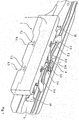
- Fig. 1
- eine dreidimensionale Ansicht eines erfindungsgemäßen Aktuierungsmittels mit transparent dargestellter Prallplatte,
- Fig. 2
- dasselbe Aktuierungsmittel mit abgenommener Prallplatte,
- Fig. 3
- Schenkel und Befestigungselement in gesonderter Darstellung,
- Fig. 4
- einen zur Aufnahme des Aktuierungsmittels geeigneten Querträger in gesonderter Darstellung,
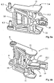
- Fig. 5
- die äußeren Schenkel eines Aktuierungsmittels nach einer anderen Ausführung der Erfindung.
- Die Richtungsangaben beziehen sich, sofern nichts Gegenteiliges ausgesagt ist, auf die Position des verbauten Aktuierungsmittels bei aufrecht stehender Rückenlehne.
- Das in
Fig. 1 gezeigte Aktuierungsmittel 1 besteht aus einer Prallplatte 2, Schenkeln 3.1 bis 3.4 sowie einem zentralen Befestigungselement 4, welche vorzugsweise durch Spitzgießen von Kunststoff gefertigt werden. Das Aktuierungsmittel 1 ist an einem aus Metall bestehenden Querträger 5 befestigt, welcher integraler Bestandteil der Metallstruktur der Rückenlehne des Fahrzeugsitzes ist oder aber nachträglich auf die im Übrigen bereits gefertigte Metallstruktur aufgesetzt wird. Das Befestigungselement 4 ist am Querträger 5 verankert und damit gegenüber der Rückenlehne ortsfest. - Die mittleren Schenkel 3.2 und 3.3 bilden mit dem Befestigungselement 4 ein gemeinsames Gelenk 6.2 aus und erstrecken sich von dort aus zur Seite in Richtung der Enden des Querträgers 5 sowie nach vorne zur Prallplatte 2. Die seitlichen Schenkel 3.1 und 3.4 sind über Gelenke 6.1 beziehungsweise 6.3 mit den mittleren Schenkeln 3.2 beziehungsweise 3.3 verbunden und im Bereich dieser Gelenke 6.1 und 6.3 in schlitzförmigen Kulissen 7.1 bis 7.4 geführt, welche aus den oberen und unteren horizontalen Kantenflächen der sich im Wesentlichen vertikal erstreckenden Prallplatte 2 ausgenommen sind. Bei einer Streckung des Schenkelzuges verlagern sich die im Bereich der Gelenke 6.1 und 6.3 an die Schenkel 3.2 und 3.4 angeformten Zapfen 8.1 und 8.2 (siehe
Fig. 2 ) in den Kulissen 7.1 bis 7.4. - Die mit ihren außenseitigen Enden von der Prallplatte 2 weg nach außen in Richtung des Querträgers 5 weisenden äußeren Schenkel 3.1 und 3.4 sind an diesen Enden mit zentralen Vorsprüngen 15.1, 15.2 ausgestattet, welche schlitzförmige Ausnehmungen 10 im Querträger 5 durchdringen und zur Anbringung der nicht gezeigten, zylinderförmigen Endfittinge der Seele (Vorsprung 15.1 des Schenkels 3.1 mit Ausnehmung 17) beziehungsweise der Hülle (Vorsprung 15.2 des Schenkels 3.4 mit Aufnahme 18) eines Bowdenzugs vorgesehen sind. Außenseitig weisen die Ausnehmungen 10 T-förmige Erweiterungen auf, welche der Durchführung der Vorsprünge 15.1, 15.2 bei der Montage der Schenkel 3.1 und 3.4 dienen. Die Schenkel 3.1 und 3.4 sind ferner außen an Ober- und Unterseite mit flachen, horizontal verlaufenden Projektionen 11 versehen, welche eine U-förmige Abkantung 12 im Querträger 5 von oben und unten umgreifen und den Schenkelzug damit streckbar führen. Außerdem weisen die Schenkel 3.1 bis 3.4 eine rahmenartige Struktur mit darin verlaufenden wabenartigen Stützrippen 16 auf, welche den Schenkeln 3.1 bis 3.4 bei geringem Gewicht eine hohe mechanische Festigkeit verleihen.
- Wie aus
Fig. 3 a bis d ersichtlich, bestehen die Gelenke 6.1 bis 6.3 aus an den Schenkeln 3.2 bis 3.4 angeformten Zapfen 8.2 und 8.3, welche in Bohrungen 9 des jeweils anderen Schenkels 3.1 bis 3.3 sowie des zentralen Befestigungselements 4 (Fig. 3e ) einsetzbar sind. Die Zapfen 8.2 und 8.3 sind hinsichtlich ihrer Länge so gestaltet, dass das nachfolgend aus der Bohrung 9 herausragende Ende des Zapfens 8.2 noch ausreichend lang ist, um eine Führung in der Kulisse 7.4 bzw. 7.2 zu ermöglichen. - Das zentrale Befestigungselement 4 weist Rasteinrichtungen 13 auf, welche von der dem Sitzinsassen zugewandten Seite des Querträgers 5 her durch eine rechteckige Aussparung 14 (
Fig. 4 ) im Querträger 5 hindurch gesteckt werden und den Querträger 5 hintergreifen. Diese Anordnung ermöglicht auch eine spätere Demontage des Aktuierungsmittels 1. - Bei der Ausbildung nach
Fig. 5a, b sind der Endfitting der Hülle des Bowdenzugs sowie die dafür vorgesehene Aufnahme 18 des Schenkels 3.4 kugelförmig ausgeformt, so dass die Hülle beim Einstecken des Endfittings nicht relativ zu dem Schenkel 3.4 ausgerichtet werden muss, sondern durch die kugelgelenkartige Verbindung selbstausrichtend ausgebildet ist. - Der an der Seele des Bowdenzugs angebrachte Endfitting ist weiterhin zylindrisch ausgeführt und wird bei der Montage in die dazu passende Aufnahme 17 im Schenkel 3.1 eingesetzt und durch einen federnden, zungenartig in Richtung der Aufnahme 17 auskragenden Clip 19 gesichert. Die Seele wird nachfolgend wie bei der Aufführung nach
Fig. 3d in einen Schlitz 20 eingeschwenkt und die Schenkel 3.2, 3.3 auf der Rückseite des Querträgers 5 überspannend zum Schenkel 3.4 hin geführt, wo sie in die Hülle des Bowdenzugs eintritt. -
- 1
- Aktuierungsmittel
- 2
- Prallplatte
- 3.1 bis 3.4
- Schenkel
- 4
- Befestigungselement
- 5
- Querträger
- 6.1 bis 6.3
- Gelenk
- 7.1 bis 7.4
- Kulisse
- 8.1 bis 8.3
- Zapfen
- 9
- Bohrung
- 10
- Ausnehmung
- 11
- Projektion
- 12
- Abkantung
- 13
- Rasteinrichtung
- 14
- Aussparung
- 15.1, 15.2
- Vorsprung
- 16
- Stützrippe
- 17
- Ausnehmung
- 18
- Aufnahme
- 19
- Clip
- 20
- Schlitz
Claims (2)
- Aktuierungsmittel (1) für die Kopfstütze eines Fahrzeugsitzes, welche bei einem Unfall zumindest in Teilen aus einer Komfortstellung in eine Sicherheitsstellung verlagerbar ist, mit Schenkeln (3.1 bis 3.4), welche infolge Druckbelastung von einer Initiaistellung aus gespreizt werden und damit eine auf Kraftübertragungsmittel übertragbare Längung bewirken, wobei die Schenkel (3.1 bis 3.4) untereinander und/oder an Befestigungselementen durch Gelenke (6.1 bis 6.3) verbunden sind, dadurch gekennzeichnet, dass die Gelenke (6.1 bis 6.3) jeweils einen langen Gelenkzapfen (8.3) und einen kurzen Gelenkzapfen (8.2) aufweisen, welche zur Ausbildung der Gelenke (6.1 bis 6.3) axial in Bohrungen (9) einführbar sind.
- Aktuierungsmittel nach Anspruch 1, dadurch gekennzeichnet, dass die äußeren Schenkel (3.1, 3.4) Vorsprünge (15.1, 15.2) aufweisen, welche die Metallstruktur des Fahrzeugsitzes insbesondere im Bereich eines Querträgers (5) von der Insassenseite her nach hinten durchdringen und zur Anbringung eines Kraftübertragungsmittels, insbesondere von Seele und Hülle eines Bowdenzugs, geeignet sind.
Applications Claiming Priority (2)
| Application Number | Priority Date | Filing Date | Title |
|---|---|---|---|
| DE102007006835A DE102007006835A1 (de) | 2007-02-07 | 2007-02-07 | Aktuierungsmittel für eine crash-aktive Kopfstütze |
| PCT/EP2008/000734 WO2008095636A1 (de) | 2007-02-07 | 2008-01-31 | Aktuierungsmittel für eine crash-aktive kopfstütze |
Publications (2)
| Publication Number | Publication Date |
|---|---|
| EP2121379A1 EP2121379A1 (de) | 2009-11-25 |
| EP2121379B1 true EP2121379B1 (de) | 2016-04-13 |
Family
ID=39323879
Family Applications (1)
| Application Number | Title | Priority Date | Filing Date |
|---|---|---|---|
| EP08707426.6A Not-in-force EP2121379B1 (de) | 2007-02-07 | 2008-01-31 | Aktuierungsmittel für eine crash-aktive kopfstütze |
Country Status (7)
| Country | Link |
|---|---|
| US (1) | US8388059B2 (de) |
| EP (1) | EP2121379B1 (de) |
| JP (1) | JP2010517853A (de) |
| KR (1) | KR101411817B1 (de) |
| CN (1) | CN101663181A (de) |
| DE (1) | DE102007006835A1 (de) |
| WO (1) | WO2008095636A1 (de) |
Families Citing this family (7)
| Publication number | Priority date | Publication date | Assignee | Title |
|---|---|---|---|---|
| DE102007041613B4 (de) | 2007-06-14 | 2009-02-26 | Johnson Controls Gmbh | Koppelungseinrichtung für ein Übertragungsmittel, insbesondere eines Fahrzeugsitzes mit crashaktiver Kopfstütze, Fahrzeugsitz und Verfahren |
| CN101678785B (zh) | 2007-06-14 | 2013-07-24 | 约翰逊控制器有限责任公司 | 尤其用于带有碰撞主动响应头枕的车辆座椅的传动装置的联结/分离机构,以及车辆座椅 |
| US7992933B2 (en) | 2007-06-21 | 2011-08-09 | Lear Corporation | Integrated vehicle seat with active head restraint system |
| US8100472B2 (en) | 2008-03-17 | 2012-01-24 | Lear Corporation | Vehicle active head restraint system with a locking linkage |
| KR101063386B1 (ko) * | 2008-11-26 | 2011-09-07 | 현대자동차주식회사 | 차량용 액티브 헤드레스트 장치 및 그 엑츄에이터 |
| US8366189B2 (en) | 2009-12-16 | 2013-02-05 | Johnson Controls Technology Company | Coupling/uncoupling device for a transmission means in particular on a vehicle seat with a crash-active headrest and vehicle seat |
| US9889776B1 (en) * | 2015-09-23 | 2018-02-13 | Christina L. Turnbo | Effective and economical car seat reminder system and kit |
Family Cites Families (13)
| Publication number | Priority date | Publication date | Assignee | Title |
|---|---|---|---|---|
| US4515424A (en) * | 1982-09-29 | 1985-05-07 | Yamaichi Electric Mfg. Co., Ltd. | Support structure for IC package and having removable closure |
| IT1280437B1 (it) * | 1995-07-19 | 1998-01-20 | Lear Seating Italia Spa | Sedile di autoveicolo |
| ES2156624T3 (es) * | 1996-11-30 | 2001-07-01 | Scharwaechter Ed Gmbh | Bisagra de puerta desenganchable para puertas de automoviles. |
| US6701573B1 (en) * | 2002-07-23 | 2004-03-09 | Joseph S. Kanfer | Fast assembly hinge |
| US7097242B2 (en) * | 2003-02-06 | 2006-08-29 | Lear Corporation | Anti-backdriving active head restraint |
| US6749256B1 (en) * | 2003-09-08 | 2004-06-15 | Lear Corporation | Vehicle seat having a movable head restraint |
| DE102004016474B3 (de) | 2004-03-31 | 2005-08-11 | Johnson Controls Gmbh | Kopfstütze, insbesondere für ein Kraftfahrzeug |
| JP4102779B2 (ja) * | 2004-06-22 | 2008-06-18 | トヨタ自動車株式会社 | 車両用シート |
| JP4118256B2 (ja) * | 2004-06-22 | 2008-07-16 | トヨタ自動車株式会社 | 車両用シート |
| JP4445346B2 (ja) * | 2004-08-19 | 2010-04-07 | 日本発條株式会社 | 車両用シート |
| DE102004048910B4 (de) * | 2004-10-06 | 2009-09-17 | Johnson Controls Gmbh | Aktuierungsmittel für eine crash-aktive Kopfstütze |
| DE102006036623B3 (de) * | 2006-08-03 | 2007-10-04 | Johnson Controls Gmbh | Aktuierungsmittel, insbesondere für Kopfstütze eines Fahrzeugsitzes |
| US7484798B2 (en) * | 2006-09-13 | 2009-02-03 | Nhk Spring Co., Ltd. | Car seat |
-
2007
- 2007-02-07 DE DE102007006835A patent/DE102007006835A1/de not_active Ceased
-
2008
- 2008-01-31 US US12/525,470 patent/US8388059B2/en not_active Expired - Fee Related
- 2008-01-31 CN CN200880004284A patent/CN101663181A/zh active Pending
- 2008-01-31 KR KR1020097017822A patent/KR101411817B1/ko not_active Expired - Fee Related
- 2008-01-31 JP JP2009548605A patent/JP2010517853A/ja active Pending
- 2008-01-31 WO PCT/EP2008/000734 patent/WO2008095636A1/de not_active Ceased
- 2008-01-31 EP EP08707426.6A patent/EP2121379B1/de not_active Not-in-force
Also Published As
| Publication number | Publication date |
|---|---|
| US20100148544A1 (en) | 2010-06-17 |
| WO2008095636A1 (de) | 2008-08-14 |
| KR101411817B1 (ko) | 2014-06-24 |
| US8388059B2 (en) | 2013-03-05 |
| JP2010517853A (ja) | 2010-05-27 |
| KR20090108722A (ko) | 2009-10-16 |
| DE102007006835A1 (de) | 2008-08-14 |
| EP2121379A1 (de) | 2009-11-25 |
| CN101663181A (zh) | 2010-03-03 |
Similar Documents
| Publication | Publication Date | Title |
|---|---|---|
| EP2013059B1 (de) | Rückenlehne mit kopfstütze, damit ausgestatteter fahrzeugsitz und montageverfahren | |
| EP2864152B1 (de) | Längseinsteller für einen fahrzeugsitz und fahrzeugsitz | |
| EP3478533B1 (de) | Längseinsteller sowie fahrzeugsitz | |
| EP2121379A1 (de) | Aktuierungsmittel für eine crash-aktive kopfstütze | |
| DE102011052268A1 (de) | Rückenlehnenvorrichtung, die mit einem Sitzpolster verriegelt ist, für ein Fahrzeug | |
| EP1897761A2 (de) | Kraftfahrzeug mit einer Überrollbügelanordnung | |
| DE102010004005A1 (de) | Feststellbremsen-Betätigungssystem mit mehreren Verbindungsgliedern | |
| DE102007041613A1 (de) | Koppelungseinrichtung für ein Übertragungsmittel, insbesondere eines Fahrzeugsitzes mit crashaktiver Kopfstütze, Fahrzeugsitz und Verfahren | |
| DE102012103919B4 (de) | Sitz mit wenigstens zweiteiligem Sitzwannenteil und Sitzmodul | |
| EP2158107B1 (de) | Koppelungs-entkoppelungseinrichtung für ein übertragungsmittlel, insbesondere eines fahrzeugsitzes mit crashaktiver kopfstütze, und fahrzeugsitz | |
| DE102013010705B4 (de) | Kopfstütze, die in x-richtung in eine sicherheitsstellung und eine komfortstellung überführbar ist | |
| DE102004042283B4 (de) | Lenksäulenanordnung | |
| DE102008032324A1 (de) | Blockiervorrichtung für einen Betätigungszug, insbesondere Bowdenzug, einer Schließvorrichtung eines beweglichen Karosserieteils eines Fahrzeugs | |
| DE10112134B4 (de) | Fahrzeugsitz mit einer Rückenlehne | |
| EP3048005B1 (de) | Rückenlehne eines fahrzeugsitzes mit einer kopfstütze | |
| DE102008050760B4 (de) | Kopfstützen-Führungsteil mit Anschlag | |
| DE19947002B4 (de) | Verriegelungsmechanismus | |
| DE102007010064B4 (de) | Fahrzeugsitz mit einer Kopfstütze | |
| DE10157516B4 (de) | Kraftfahrzeug-Sitz | |
| WO2014191302A1 (de) | Knieaufprallschutzeinrichtung für ein kraftfahrzeug | |
| DE202007006910U1 (de) | Sitzhöhenverstelleinrichtung sowie Kraftfahrzeugsitz | |
| DE10353449B4 (de) | Lagerbock, insbesondere Mittellager, zur schwenkbaren Anlenkung von Sitzlehnen in einem Fahrzeug, insbesondere zur schwenkbaren Anlenkung von getrennt umlegbaren Sitzlehnen einer Rücksitzbank eines Kraftfahrzeuges | |
| DE102017210352B4 (de) | Fahrzeugsitz, insbesondere kraftfahrzeugsitz | |
| DE20201327U1 (de) | Vorrichtung zum Verankern eines Sitzes an einem Fahrzeugboden | |
| DE102010020568B4 (de) | Verstellvorrichtung für eine Höhenverstelleinrichtung eines Sitzes und eine Neigungsverstelleinrichtung einer Rückenlehne des Sitzes |
Legal Events
| Date | Code | Title | Description |
|---|---|---|---|
| PUAI | Public reference made under article 153(3) epc to a published international application that has entered the european phase |
Free format text: ORIGINAL CODE: 0009012 |
|
| 17P | Request for examination filed |
Effective date: 20090907 |
|
| AK | Designated contracting states |
Kind code of ref document: A1 Designated state(s): AT BE BG CH CY CZ DE DK EE ES FI FR GB GR HR HU IE IS IT LI LT LU LV MC MT NL NO PL PT RO SE SI SK TR |
|
| RIN1 | Information on inventor provided before grant (corrected) |
Inventor name: SPERLING, KLAUS Inventor name: THIES, MARCUS Inventor name: HARTLAUB, SILVIO Inventor name: GUENTHER, BENJAMIN Inventor name: HESTERBERG, JOSHUA |
|
| RIN1 | Information on inventor provided before grant (corrected) |
Inventor name: SPERLING, KLAUS Inventor name: HESTERBERG, JOSHUA Inventor name: HARTLAUB, SILVIO Inventor name: THIES, MARCUS Inventor name: GUENTHER, BENJAMIN |
|
| DAX | Request for extension of the european patent (deleted) | ||
| 17Q | First examination report despatched |
Effective date: 20111010 |
|
| GRAP | Despatch of communication of intention to grant a patent |
Free format text: ORIGINAL CODE: EPIDOSNIGR1 |
|
| INTG | Intention to grant announced |
Effective date: 20151030 |
|
| GRAS | Grant fee paid |
Free format text: ORIGINAL CODE: EPIDOSNIGR3 |
|
| GRAA | (expected) grant |
Free format text: ORIGINAL CODE: 0009210 |
|
| AK | Designated contracting states |
Kind code of ref document: B1 Designated state(s): AT BE BG CH CY CZ DE DK EE ES FI FR GB GR HR HU IE IS IT LI LT LU LV MC MT NL NO PL PT RO SE SI SK TR |
|
| REG | Reference to a national code |
Ref country code: GB Ref legal event code: FG4D Free format text: NOT ENGLISH |
|
| REG | Reference to a national code |
Ref country code: AT Ref legal event code: REF Ref document number: 789734 Country of ref document: AT Kind code of ref document: T Effective date: 20160415 Ref country code: CH Ref legal event code: EP |
|
| REG | Reference to a national code |
Ref country code: IE Ref legal event code: FG4D Free format text: LANGUAGE OF EP DOCUMENT: GERMAN |
|
| REG | Reference to a national code |
Ref country code: DE Ref legal event code: R096 Ref document number: 502008014079 Country of ref document: DE |
|
| REG | Reference to a national code |
Ref country code: LT Ref legal event code: MG4D |
|
| REG | Reference to a national code |
Ref country code: NL Ref legal event code: MP Effective date: 20160413 |
|
| PG25 | Lapsed in a contracting state [announced via postgrant information from national office to epo] |
Ref country code: FI Free format text: LAPSE BECAUSE OF FAILURE TO SUBMIT A TRANSLATION OF THE DESCRIPTION OR TO PAY THE FEE WITHIN THE PRESCRIBED TIME-LIMIT Effective date: 20160413 Ref country code: NL Free format text: LAPSE BECAUSE OF FAILURE TO SUBMIT A TRANSLATION OF THE DESCRIPTION OR TO PAY THE FEE WITHIN THE PRESCRIBED TIME-LIMIT Effective date: 20160413 Ref country code: LT Free format text: LAPSE BECAUSE OF FAILURE TO SUBMIT A TRANSLATION OF THE DESCRIPTION OR TO PAY THE FEE WITHIN THE PRESCRIBED TIME-LIMIT Effective date: 20160413 Ref country code: NO Free format text: LAPSE BECAUSE OF FAILURE TO SUBMIT A TRANSLATION OF THE DESCRIPTION OR TO PAY THE FEE WITHIN THE PRESCRIBED TIME-LIMIT Effective date: 20160713 Ref country code: PL Free format text: LAPSE BECAUSE OF FAILURE TO SUBMIT A TRANSLATION OF THE DESCRIPTION OR TO PAY THE FEE WITHIN THE PRESCRIBED TIME-LIMIT Effective date: 20160413 |
|
| PG25 | Lapsed in a contracting state [announced via postgrant information from national office to epo] |
Ref country code: SE Free format text: LAPSE BECAUSE OF FAILURE TO SUBMIT A TRANSLATION OF THE DESCRIPTION OR TO PAY THE FEE WITHIN THE PRESCRIBED TIME-LIMIT Effective date: 20160413 Ref country code: ES Free format text: LAPSE BECAUSE OF FAILURE TO SUBMIT A TRANSLATION OF THE DESCRIPTION OR TO PAY THE FEE WITHIN THE PRESCRIBED TIME-LIMIT Effective date: 20160413 Ref country code: LV Free format text: LAPSE BECAUSE OF FAILURE TO SUBMIT A TRANSLATION OF THE DESCRIPTION OR TO PAY THE FEE WITHIN THE PRESCRIBED TIME-LIMIT Effective date: 20160413 Ref country code: GR Free format text: LAPSE BECAUSE OF FAILURE TO SUBMIT A TRANSLATION OF THE DESCRIPTION OR TO PAY THE FEE WITHIN THE PRESCRIBED TIME-LIMIT Effective date: 20160714 Ref country code: HR Free format text: LAPSE BECAUSE OF FAILURE TO SUBMIT A TRANSLATION OF THE DESCRIPTION OR TO PAY THE FEE WITHIN THE PRESCRIBED TIME-LIMIT Effective date: 20160413 Ref country code: PT Free format text: LAPSE BECAUSE OF FAILURE TO SUBMIT A TRANSLATION OF THE DESCRIPTION OR TO PAY THE FEE WITHIN THE PRESCRIBED TIME-LIMIT Effective date: 20160816 |
|
| PG25 | Lapsed in a contracting state [announced via postgrant information from national office to epo] |
Ref country code: IT Free format text: LAPSE BECAUSE OF FAILURE TO SUBMIT A TRANSLATION OF THE DESCRIPTION OR TO PAY THE FEE WITHIN THE PRESCRIBED TIME-LIMIT Effective date: 20160413 |
|
| REG | Reference to a national code |
Ref country code: DE Ref legal event code: R097 Ref document number: 502008014079 Country of ref document: DE |
|
| REG | Reference to a national code |
Ref country code: FR Ref legal event code: PLFP Year of fee payment: 10 |
|
| PG25 | Lapsed in a contracting state [announced via postgrant information from national office to epo] |
Ref country code: CZ Free format text: LAPSE BECAUSE OF FAILURE TO SUBMIT A TRANSLATION OF THE DESCRIPTION OR TO PAY THE FEE WITHIN THE PRESCRIBED TIME-LIMIT Effective date: 20160413 Ref country code: EE Free format text: LAPSE BECAUSE OF FAILURE TO SUBMIT A TRANSLATION OF THE DESCRIPTION OR TO PAY THE FEE WITHIN THE PRESCRIBED TIME-LIMIT Effective date: 20160413 Ref country code: RO Free format text: LAPSE BECAUSE OF FAILURE TO SUBMIT A TRANSLATION OF THE DESCRIPTION OR TO PAY THE FEE WITHIN THE PRESCRIBED TIME-LIMIT Effective date: 20160413 Ref country code: SK Free format text: LAPSE BECAUSE OF FAILURE TO SUBMIT A TRANSLATION OF THE DESCRIPTION OR TO PAY THE FEE WITHIN THE PRESCRIBED TIME-LIMIT Effective date: 20160413 Ref country code: DK Free format text: LAPSE BECAUSE OF FAILURE TO SUBMIT A TRANSLATION OF THE DESCRIPTION OR TO PAY THE FEE WITHIN THE PRESCRIBED TIME-LIMIT Effective date: 20160413 |
|
| PLBE | No opposition filed within time limit |
Free format text: ORIGINAL CODE: 0009261 |
|
| STAA | Information on the status of an ep patent application or granted ep patent |
Free format text: STATUS: NO OPPOSITION FILED WITHIN TIME LIMIT |
|
| 26N | No opposition filed |
Effective date: 20170116 |
|
| REG | Reference to a national code |
Ref country code: DE Ref legal event code: R081 Ref document number: 502008014079 Country of ref document: DE Owner name: ADIENT US LLC, PLYMOUTH, US Free format text: FORMER OWNER: JOHNSON CONTROLS GMBH, 51399 BURSCHEID, DE Ref country code: DE Ref legal event code: R081 Ref document number: 502008014079 Country of ref document: DE Owner name: ADIENT LUXEMBOURG HOLDING S.A.R.L., LU Free format text: FORMER OWNER: JOHNSON CONTROLS GMBH, 51399 BURSCHEID, DE Ref country code: DE Ref legal event code: R081 Ref document number: 502008014079 Country of ref document: DE Owner name: ADIENT LUXEMBOURG HOLDING S.A R.L., LU Free format text: FORMER OWNER: JOHNSON CONTROLS GMBH, 51399 BURSCHEID, DE |
|
| PG25 | Lapsed in a contracting state [announced via postgrant information from national office to epo] |
Ref country code: BE Free format text: LAPSE BECAUSE OF NON-PAYMENT OF DUE FEES Effective date: 20170131 Ref country code: SI Free format text: LAPSE BECAUSE OF FAILURE TO SUBMIT A TRANSLATION OF THE DESCRIPTION OR TO PAY THE FEE WITHIN THE PRESCRIBED TIME-LIMIT Effective date: 20160413 |
|
| REG | Reference to a national code |
Ref country code: CH Ref legal event code: PL |
|
| GBPC | Gb: european patent ceased through non-payment of renewal fee |
Effective date: 20170131 |
|
| PG25 | Lapsed in a contracting state [announced via postgrant information from national office to epo] |
Ref country code: MC Free format text: LAPSE BECAUSE OF FAILURE TO SUBMIT A TRANSLATION OF THE DESCRIPTION OR TO PAY THE FEE WITHIN THE PRESCRIBED TIME-LIMIT Effective date: 20160413 |
|
| PG25 | Lapsed in a contracting state [announced via postgrant information from national office to epo] |
Ref country code: LI Free format text: LAPSE BECAUSE OF NON-PAYMENT OF DUE FEES Effective date: 20170131 Ref country code: CH Free format text: LAPSE BECAUSE OF NON-PAYMENT OF DUE FEES Effective date: 20170131 |
|
| REG | Reference to a national code |
Ref country code: IE Ref legal event code: MM4A |
|
| REG | Reference to a national code |
Ref country code: DE Ref legal event code: R079 Ref document number: 502008014079 Country of ref document: DE Free format text: PREVIOUS MAIN CLASS: B60N0002480000 Ipc: B60N0002800000 |
|
| PG25 | Lapsed in a contracting state [announced via postgrant information from national office to epo] |
Ref country code: GB Free format text: LAPSE BECAUSE OF NON-PAYMENT OF DUE FEES Effective date: 20170131 Ref country code: LU Free format text: LAPSE BECAUSE OF NON-PAYMENT OF DUE FEES Effective date: 20170131 |
|
| REG | Reference to a national code |
Ref country code: FR Ref legal event code: PLFP Year of fee payment: 11 |
|
| REG | Reference to a national code |
Ref country code: BE Ref legal event code: MM Effective date: 20170131 |
|
| PG25 | Lapsed in a contracting state [announced via postgrant information from national office to epo] |
Ref country code: IE Free format text: LAPSE BECAUSE OF NON-PAYMENT OF DUE FEES Effective date: 20170131 |
|
| REG | Reference to a national code |
Ref country code: AT Ref legal event code: MM01 Ref document number: 789734 Country of ref document: AT Kind code of ref document: T Effective date: 20170131 |
|
| REG | Reference to a national code |
Ref country code: DE Ref legal event code: R081 Ref document number: 502008014079 Country of ref document: DE Owner name: ADIENT US LLC, PLYMOUTH, US Free format text: FORMER OWNER: ADIENT LUXEMBOURG HOLDING S.A.R.L., LUXEMBOURG, LU Ref country code: DE Ref legal event code: R081 Ref document number: 502008014079 Country of ref document: DE Owner name: ADIENT LUXEMBOURG HOLDING S.A R.L., LU Free format text: FORMER OWNER: ADIENT LUXEMBOURG HOLDING S.A.R.L., LUXEMBOURG, LU |
|
| PG25 | Lapsed in a contracting state [announced via postgrant information from national office to epo] |
Ref country code: AT Free format text: LAPSE BECAUSE OF NON-PAYMENT OF DUE FEES Effective date: 20170131 |
|
| PG25 | Lapsed in a contracting state [announced via postgrant information from national office to epo] |
Ref country code: MT Free format text: LAPSE BECAUSE OF FAILURE TO SUBMIT A TRANSLATION OF THE DESCRIPTION OR TO PAY THE FEE WITHIN THE PRESCRIBED TIME-LIMIT Effective date: 20160413 |
|
| PG25 | Lapsed in a contracting state [announced via postgrant information from national office to epo] |
Ref country code: HU Free format text: LAPSE BECAUSE OF FAILURE TO SUBMIT A TRANSLATION OF THE DESCRIPTION OR TO PAY THE FEE WITHIN THE PRESCRIBED TIME-LIMIT; INVALID AB INITIO Effective date: 20080131 |
|
| PG25 | Lapsed in a contracting state [announced via postgrant information from national office to epo] |
Ref country code: BG Free format text: LAPSE BECAUSE OF FAILURE TO SUBMIT A TRANSLATION OF THE DESCRIPTION OR TO PAY THE FEE WITHIN THE PRESCRIBED TIME-LIMIT Effective date: 20160413 |
|
| PG25 | Lapsed in a contracting state [announced via postgrant information from national office to epo] |
Ref country code: CY Free format text: LAPSE BECAUSE OF NON-PAYMENT OF DUE FEES Effective date: 20160413 |
|
| PG25 | Lapsed in a contracting state [announced via postgrant information from national office to epo] |
Ref country code: TR Free format text: LAPSE BECAUSE OF FAILURE TO SUBMIT A TRANSLATION OF THE DESCRIPTION OR TO PAY THE FEE WITHIN THE PRESCRIBED TIME-LIMIT Effective date: 20160413 |
|
| PG25 | Lapsed in a contracting state [announced via postgrant information from national office to epo] |
Ref country code: IS Free format text: LAPSE BECAUSE OF FAILURE TO SUBMIT A TRANSLATION OF THE DESCRIPTION OR TO PAY THE FEE WITHIN THE PRESCRIBED TIME-LIMIT Effective date: 20160813 |
|
| REG | Reference to a national code |
Ref country code: DE Ref legal event code: R082 Ref document number: 502008014079 Country of ref document: DE Representative=s name: LIEDHEGENER, RALF, DIPL.-ING., DE |
|
| PGFP | Annual fee paid to national office [announced via postgrant information from national office to epo] |
Ref country code: DE Payment date: 20220127 Year of fee payment: 15 |
|
| PGFP | Annual fee paid to national office [announced via postgrant information from national office to epo] |
Ref country code: FR Payment date: 20220125 Year of fee payment: 15 |
|
| REG | Reference to a national code |
Ref country code: DE Ref legal event code: R081 Ref document number: 502008014079 Country of ref document: DE Owner name: ADIENT US LLC, PLYMOUTH, US Free format text: FORMER OWNER: ADIENT LUXEMBOURG HOLDING S.A R.L., LUXEMBOURG, LU |
|
| REG | Reference to a national code |
Ref country code: DE Ref legal event code: R119 Ref document number: 502008014079 Country of ref document: DE |
|
| PG25 | Lapsed in a contracting state [announced via postgrant information from national office to epo] |
Ref country code: DE Free format text: LAPSE BECAUSE OF NON-PAYMENT OF DUE FEES Effective date: 20230801 |
|
| PG25 | Lapsed in a contracting state [announced via postgrant information from national office to epo] |
Ref country code: FR Free format text: LAPSE BECAUSE OF NON-PAYMENT OF DUE FEES Effective date: 20230131 |