EP2121198B1 - Verfahren zum direktbedrucken von holzwerkstoffplatten - Google Patents
Verfahren zum direktbedrucken von holzwerkstoffplatten Download PDFInfo
- Publication number
- EP2121198B1 EP2121198B1 EP07846752A EP07846752A EP2121198B1 EP 2121198 B1 EP2121198 B1 EP 2121198B1 EP 07846752 A EP07846752 A EP 07846752A EP 07846752 A EP07846752 A EP 07846752A EP 2121198 B1 EP2121198 B1 EP 2121198B1
- Authority
- EP
- European Patent Office
- Prior art keywords
- layer
- plastic material
- board
- coating
- web
- Prior art date
- Legal status (The legal status is an assumption and is not a legal conclusion. Google has not performed a legal analysis and makes no representation as to the accuracy of the status listed.)
- Active
Links
- 238000000034 method Methods 0.000 title claims abstract description 37
- 239000000463 material Substances 0.000 title claims description 155
- 239000002023 wood Substances 0.000 title claims description 39
- 238000000576 coating method Methods 0.000 claims abstract description 61
- 239000011248 coating agent Substances 0.000 claims abstract description 59
- 238000001035 drying Methods 0.000 claims abstract description 9
- 239000004033 plastic Substances 0.000 claims description 60
- 229920003023 plastic Polymers 0.000 claims description 60
- 239000002245 particle Substances 0.000 claims description 35
- 238000005299 abrasion Methods 0.000 claims description 27
- NIXOWILDQLNWCW-UHFFFAOYSA-M Acrylate Chemical compound [O-]C(=O)C=C NIXOWILDQLNWCW-UHFFFAOYSA-M 0.000 claims description 12
- 229910052593 corundum Inorganic materials 0.000 claims description 9
- 239000010431 corundum Substances 0.000 claims description 9
- 230000009969 flowable effect Effects 0.000 claims description 9
- 238000006116 polymerization reaction Methods 0.000 claims description 6
- 230000005855 radiation Effects 0.000 claims description 6
- 230000000694 effects Effects 0.000 claims description 3
- 238000005520 cutting process Methods 0.000 claims description 2
- 239000010410 layer Substances 0.000 claims 19
- 239000002356 single layer Substances 0.000 claims 2
- 238000004049 embossing Methods 0.000 claims 1
- 239000002184 metal Substances 0.000 claims 1
- 239000010902 straw Substances 0.000 claims 1
- -1 tree needles Substances 0.000 claims 1
- 239000007788 liquid Substances 0.000 abstract description 12
- 230000008569 process Effects 0.000 abstract description 5
- 238000010894 electron beam technology Methods 0.000 abstract description 3
- NIXOWILDQLNWCW-UHFFFAOYSA-N acrylic acid group Chemical group C(C=C)(=O)O NIXOWILDQLNWCW-UHFFFAOYSA-N 0.000 abstract description 2
- 239000011093 chipboard Substances 0.000 abstract description 2
- 239000003795 chemical substances by application Substances 0.000 abstract 1
- 239000011094 fiberboard Substances 0.000 abstract 1
- 230000032258 transport Effects 0.000 description 15
- 239000012876 carrier material Substances 0.000 description 13
- 239000010408 film Substances 0.000 description 12
- 239000007787 solid Substances 0.000 description 8
- 239000004922 lacquer Substances 0.000 description 6
- 238000004519 manufacturing process Methods 0.000 description 6
- 230000003287 optical effect Effects 0.000 description 6
- 239000003973 paint Substances 0.000 description 6
- 238000006243 chemical reaction Methods 0.000 description 4
- 238000005034 decoration Methods 0.000 description 3
- 230000007717 exclusion Effects 0.000 description 3
- 239000000123 paper Substances 0.000 description 3
- 239000010409 thin film Substances 0.000 description 3
- 239000003082 abrasive agent Substances 0.000 description 2
- 125000005396 acrylic acid ester group Chemical group 0.000 description 2
- 238000004132 cross linking Methods 0.000 description 2
- 230000006872 improvement Effects 0.000 description 2
- 239000000203 mixture Substances 0.000 description 2
- 238000012805 post-processing Methods 0.000 description 2
- 239000011347 resin Substances 0.000 description 2
- 229920005989 resin Polymers 0.000 description 2
- 241000894007 species Species 0.000 description 2
- 239000000126 substance Substances 0.000 description 2
- 239000002966 varnish Substances 0.000 description 2
- SMZOUWXMTYCWNB-UHFFFAOYSA-N 2-(2-methoxy-5-methylphenyl)ethanamine Chemical compound COC1=CC=C(C)C=C1CCN SMZOUWXMTYCWNB-UHFFFAOYSA-N 0.000 description 1
- 239000004925 Acrylic resin Substances 0.000 description 1
- 229920000178 Acrylic resin Polymers 0.000 description 1
- 244000025254 Cannabis sativa Species 0.000 description 1
- 235000012766 Cannabis sativa ssp. sativa var. sativa Nutrition 0.000 description 1
- 235000012765 Cannabis sativa ssp. sativa var. spontanea Nutrition 0.000 description 1
- 239000002390 adhesive tape Substances 0.000 description 1
- 230000015572 biosynthetic process Effects 0.000 description 1
- 235000009120 camo Nutrition 0.000 description 1
- 235000005607 chanvre indien Nutrition 0.000 description 1
- 150000001875 compounds Chemical class 0.000 description 1
- 238000010924 continuous production Methods 0.000 description 1
- 239000007799 cork Substances 0.000 description 1
- 238000000354 decomposition reaction Methods 0.000 description 1
- 239000006185 dispersion Substances 0.000 description 1
- 230000005284 excitation Effects 0.000 description 1
- 238000007306 functionalization reaction Methods 0.000 description 1
- 239000011487 hemp Substances 0.000 description 1
- 238000005304 joining Methods 0.000 description 1
- 239000011344 liquid material Substances 0.000 description 1
- 239000002923 metal particle Substances 0.000 description 1
- 238000003801 milling Methods 0.000 description 1
- 229930014626 natural product Natural products 0.000 description 1
- 230000006855 networking Effects 0.000 description 1
- 238000010422 painting Methods 0.000 description 1
- 238000000059 patterning Methods 0.000 description 1
- 238000006068 polycondensation reaction Methods 0.000 description 1
- 229920000728 polyester Polymers 0.000 description 1
- 229920000642 polymer Polymers 0.000 description 1
- 229920002635 polyurethane Polymers 0.000 description 1
- 239000004814 polyurethane Substances 0.000 description 1
- 230000037452 priming Effects 0.000 description 1
- 230000001953 sensory effect Effects 0.000 description 1
- 230000035939 shock Effects 0.000 description 1
- 229920003002 synthetic resin Polymers 0.000 description 1
- 239000000057 synthetic resin Substances 0.000 description 1
- 210000002268 wool Anatomy 0.000 description 1
Images

Classifications
-
- B—PERFORMING OPERATIONS; TRANSPORTING
- B05—SPRAYING OR ATOMISING IN GENERAL; APPLYING FLUENT MATERIALS TO SURFACES, IN GENERAL
- B05D—PROCESSES FOR APPLYING FLUENT MATERIALS TO SURFACES, IN GENERAL
- B05D7/00—Processes, other than flocking, specially adapted for applying liquids or other fluent materials to particular surfaces or for applying particular liquids or other fluent materials
- B05D7/06—Processes, other than flocking, specially adapted for applying liquids or other fluent materials to particular surfaces or for applying particular liquids or other fluent materials to wood
-
- B—PERFORMING OPERATIONS; TRANSPORTING
- B05—SPRAYING OR ATOMISING IN GENERAL; APPLYING FLUENT MATERIALS TO SURFACES, IN GENERAL
- B05D—PROCESSES FOR APPLYING FLUENT MATERIALS TO SURFACES, IN GENERAL
- B05D1/00—Processes for applying liquids or other fluent materials
- B05D1/40—Distributing applied liquids or other fluent materials by members moving relatively to surface
-
- B—PERFORMING OPERATIONS; TRANSPORTING
- B05—SPRAYING OR ATOMISING IN GENERAL; APPLYING FLUENT MATERIALS TO SURFACES, IN GENERAL
- B05D—PROCESSES FOR APPLYING FLUENT MATERIALS TO SURFACES, IN GENERAL
- B05D3/00—Pretreatment of surfaces to which liquids or other fluent materials are to be applied; After-treatment of applied coatings, e.g. intermediate treating of an applied coating preparatory to subsequent applications of liquids or other fluent materials
- B05D3/06—Pretreatment of surfaces to which liquids or other fluent materials are to be applied; After-treatment of applied coatings, e.g. intermediate treating of an applied coating preparatory to subsequent applications of liquids or other fluent materials by exposure to radiation
- B05D3/061—Pretreatment of surfaces to which liquids or other fluent materials are to be applied; After-treatment of applied coatings, e.g. intermediate treating of an applied coating preparatory to subsequent applications of liquids or other fluent materials by exposure to radiation using U.V.
- B05D3/065—After-treatment
- B05D3/067—Curing or cross-linking the coating
-
- B—PERFORMING OPERATIONS; TRANSPORTING
- B05—SPRAYING OR ATOMISING IN GENERAL; APPLYING FLUENT MATERIALS TO SURFACES, IN GENERAL
- B05D—PROCESSES FOR APPLYING FLUENT MATERIALS TO SURFACES, IN GENERAL
- B05D5/00—Processes for applying liquids or other fluent materials to surfaces to obtain special surface effects, finishes or structures
- B05D5/06—Processes for applying liquids or other fluent materials to surfaces to obtain special surface effects, finishes or structures to obtain multicolour or other optical effects
-
- B—PERFORMING OPERATIONS; TRANSPORTING
- B05—SPRAYING OR ATOMISING IN GENERAL; APPLYING FLUENT MATERIALS TO SURFACES, IN GENERAL
- B05D—PROCESSES FOR APPLYING FLUENT MATERIALS TO SURFACES, IN GENERAL
- B05D5/00—Processes for applying liquids or other fluent materials to surfaces to obtain special surface effects, finishes or structures
- B05D5/02—Processes for applying liquids or other fluent materials to surfaces to obtain special surface effects, finishes or structures to obtain a matt or rough surface
Definitions
- the invention relates to a method for the coating of boards, in particular of wood-based panels for the production of floor panels, with a flowable coating material.
- Laminate panels essentially consist of an approx. 6 to 8 mm thick base plate made of MDF or HDF material, to which a decor paper layer is glued. The decor paper layer is impregnated with a resin and is usually further provided with abrasion-resistant particles.
- the application of pressure and heat hardens the resin and creates an extremely abrasion-resistant and decorative surface.
- new methods have been developed to print wood-based panels, such as MDF or HDF, directly with a plastic material, ie without the use of decorative paper.
- the MDF board for example, is sanded off and primed.
- a colored decor is printed on this primer, for example a wood decor.
- a plurality of very thin material layers are applied, wherein the individual material layers each cured before applying the next layer.
- the material layers are, for example, a plurality of, essentially transparent lacquer layers of a hardenable plastic.
- the resulting overall layer thus has a layered structure.
- the individual layers Between the individual layers arise interfaces in which no good networking takes place.
- the individual layers usually have a thickness of 10 to 15 .mu.m and usually 5 to 7 layers are applied one above the other, resulting in a total thickness of the thin-layer system or layer stack of about 50-105 .mu.m.
- wood-based panel this includes all wood-based materials in the broadest sense, ie panels that are made of wood, or that are made using wood materials. These include, but are not limited to, OSB panels, MDF or HDF, chipboard, solid and solid wood, veneered and prefinished parquet and others.
- this invention relates to improved wood-based panels for use as a floor covering or wall or ceiling covering.
- U1 is a device for the coating of plates in the run out.
- Several plates are arranged on a conveyor belt, which are fed one after the other, inter alia coating stations.
- Such a coating station comprises an applicator roll, with which a lacquer is applied to a plate.
- an applicator roll with which a lacquer is applied to a plate.
- the applicator roll may include a textured surface to pattern lacquer on the surface of a plate.
- the coatings consist for example of liquid plastics or synthetic resins to be cured by a brief thermal shock to a film.
- a device which comprises transport means for the transport of plates.
- the device also comprises a supply device with which coating material can be brought onto the plate surface. Subsequent to the feeding device, means for drying and / or curing the coating material are provided above the plate.
- the device comprises means to be able to pass a material web between the transport means for the transport of plates and the means for drying and / or curing.
- the surface of the coating material can according to the invention be provided with a structure without having to exert high pressure. Since the coating material is dried and / or cured in this state, it is thus possible to coat a plate with a structured surface, without this being the case in the publication DE 20 2004 018 710 U1 known prior art either have to use a press or a complex printing unit. Also, a multi-step coating can thus be uniformly dried and / or cured in one operation. Above all, it is possible that a chemical network extends through the entire structure of the layer, resulting in a particularly stable coating.
- drying and / or curing under exclusion of air is possible. Drying and / or curing under exclusion of air is frequently desired, for example in order to achieve particularly high crosslinking in the case of curing of a varnish with UV light, ie a particularly high conversion of double bonds within the varnish. In the case of curing with electron beams, an air seal is usually required.
- the invention relates to a novel process for coating a wood-based panel, in particular a particleboard, MDF or HDF board, with a flowable plastic material.
- the method relates to the production of panels, such as the manufacture of floor panels.
- a thick layer of at least 30 .mu.m of a plastic material is applied to the wood-based panel in a single step.
- the plastic material is preferably transparent at least after drying or curing.
- the layer is preferably applied in a single operation in a thickness of 30 to 150 microns, more preferably in a thickness of 80 to 110 microns and most preferably in a thickness applied by about 95 microns.
- the layer of plastic material is cured.
- abrasion-resistant particles such as, for example, larger corundum particles
- the individual thin layers only have a thickness of 10 to 15 .mu.m, and which are cured one after the other, in fact only relatively small particles can be used, since the particles are preferably incorporated as far as possible in the layers should be.
- the flowable plastic material is preferably an acrylate system.
- an acrylate system is meant, for example, a polymerizable mixture of double bond-containing mono-, di- and polyfunctional acrylic acid-based compounds. Typical representatives are for example Dipropylenglycoldiacrylat, 1,6-Hexandioldiacrylat, polyurethane acrylic acid ester, polyester acrylic acid ester as they are available in the production program of the company BASF under the trade name Laromer TM types on the market.
- the wood-based panel is preferably provided with a colored decorative print prior to coating with the flowable plastic material, e.g. with a wood decor.
- the plastic material is applied via the decor pressure and is preferably as transparent as possible. The process can be carried out, for example, as follows:
- the carrier plate such as an MDF plate
- a primer is applied and preferably applied a primer.
- the decoration is printed on the primer or the primer.
- a further primer is applied, which is preferably a suitable primer for the following layer of plastic material.
- This primer is preferably applied in an amount of up to 10 g / m 2 , more preferably of about 5 g / m 2 .
- a single thick layer of an acrylate system is applied to the primer by, for example, roller application. This is preferably done in an amount of up to 100 g / m 2 , more preferably of about 65 g / m 2 .
- the plastic material is preferably a polymerizable acrylate system.
- the plastic material such as the polymerizable acrylate system, a UV-curable plastic.
- the UV radiation serves to start the polymerization. Since the polymerization can be stopped at any time, it is thus possible in the single thick layer, e.g. May be 95 microns, a Vernetzungsgradienten and thus produce a cure gradients.
- the curing gradient is generated over a single, over the entire layer thickness occurring polymerization with the highest possible conversion. This is in contrast to painting with many thin films, which are applied layer by layer and then "gelled” by radiation, i. it is prematurely aborted the reaction. Thus, over the entire cross-section of all layers, there is no continuous polymer formation but boundary layers.
- ⁇ layers are applied wet-on-wet (for example primer, acrylate (roll application), corundum, topcoat application) and polymerized in a single step, preferably by UV excitation.
- the acrylate layer is cured according to the invention in a single thick layer.
- the individual layers differ in their function and thus also in the chemical structure:
- the primer has the task of producing good adhesion between the printing and the plastic layer.
- the middle layer is flexibly adjusted to reduce internal stresses and to avoid embrittlement and to absorb impact energy when walking when the coated board is used as a floor panel, for example.
- the Toplack Anlagen however, it is modified to lead to high hardness and scratch resistance.
- the polymerization is carried out so that a nearly complete double bond conversion over the entire layer is achieved.
- the primer is preferably designed so that better adhesion is achieved by greater functionalization of the acrylate mixture.
- the middle layer has chain growth and only minor cross-linking.
- the Toplack Anlagen preferably contains a highly crosslinkable acrylate system.
- abrasion-resistant particles in particular corundum particles
- corundum particles are preferably introduced into the layer. Since the layer is very thick, it is possible to incorporate relatively thick particles which have better abrasion properties than smaller particles.
- abrasion-resistant particles in particular corundum particles
- Particular preference is given to using particles in the range from DF 240 to DF 280, ie having particle sizes D 50 of 44.5 to 36.5 ⁇ m.
- relatively small particles such as corundum particles
- the particle size is usually in the range of DF 320 to DF 500 according to the FEPA specification. That is, the previously usable grain sizes of the abrasion-resistant particles were limited to an average grain size D 50 of 29.2 to 12.8 microns.
- These relatively small particles lead to lower abrasion values with the same additional amount, ie with the same abrasion class, a larger amount by weight must be used with finer particles than with larger particles. In addition, finer particles lead to a poorer transparency of the surface and graying phenomena.
- the introduction of the particles into the layer can be carried out after application of the layer in which the particles are sprinkled, for example, on the not yet cured layer. After the particles have sunk or pressed into the layer, the material is cured so that the particles are firmly entrapped in the layer. Another possibility is to introduce the particles before the application of the layer in the flowable plastic material, for example in the form of a dispersion.
- a material web having a structured surface is applied to the layer of plastic material.
- a structure is embossed in the layer of plastic material. Since the layer is still liquid at this time, virtually no pressure needs to be expended.
- the layer of plastic material is dried and / or cured, whereby the introduced into the layer of plastic material structure is fixed. Thereafter, in a further step, the material web with structured surface can be removed again.
- a pattern roll is used to emboss a structure in the layer of plastic material.
- the layer of plastic material is dried and / or hardened, whereby the structure introduced into the layer of plastic material is fixed. Due to the thickness of the layer according to the invention, structure depths of 0 to 80 ⁇ m are possible. Structural depths of from 20 to 80 ⁇ m and particularly preferably up to about 35 ⁇ m are particularly preferred. In the prior art, in which a layer system of individual thin films was used, it was not possible to produce structure depths of more than 5 to 10 microns. These small structure depths are not sufficient for many purposes.
- a material web with a smooth surface is applied to the layer of plastic material without exerting much pressure. In this way it is prevented that air gets to the plastic material.
- the layer of plastic material is dried and / or cured in the absence of air.
- the material web with a smooth surface is removed again.
- the material webs used are preferably permeable to UV light. If a UV-curable plastic is used, it is thus possible to cure the plastic, although it is covered by the material web.
- the presented method offers particular advantages in the coating of wood-based panels made of real wood, such as veneer or parquet, for example, engineered parquet. So far, it has been a disadvantage of such real wood panels that the surfaces are relatively sensitive. With the method according to the invention, real wood floors can now also be provided with a coating which has high abrasion values and which nevertheless has an aesthetically pleasing surface due to the incorporated three-dimensional structure. If real wood floors were previously provided with an abrasion-resistant coating in order to increase the durability of, for example, floors made of this material, the natural three-dimensional structure of the real wood has proven to be disadvantageous.
- the paint or coating applied in the wet state tends to flow into the recesses of the natural structure, so that the coating of the protruding portions between the recesses is insufficient.
- the natural three-dimensional structure of the real wood is completely filled up, resulting in an undesirably flat surface.
- a flat surface impairs the optical effect caused by the three-dimensional Structures to be achieved; that is, to create or emphasize the impression of a real wood material.
- the problem of filling the natural structure of the real wood occurs even at very low thicknesses of the coating. The prior art has attempted to avoid this problem by machine-milling deeper structures into the real wood surface.
- the supply device comprises a coating material catcher disposed adjacent to the transport means for transporting the plates.
- the collecting device further adjoins a roller for transporting the material web.
- the collecting device is designed so that liquid, located in the catcher coating material flows to the roller. It is thus achieved that, given a sufficiently large filling of the collecting device, liquid coating material can completely coat a material web with a liquid film when a material web is transported over the roller. Overall, it can be achieved with sufficient supply of liquid coating material that the liquid coating material completely fills the space between the surface of a plate and the material web located above it. It then gets very reliable no air in the area. Curing can be carried out so particularly reliably under exclusion of air.
- relatively thick paint layers having a total thickness of, for example, 80 to 100 ⁇ m in thickness and to uniformly dry and cure.
- This makes it possible to embed relatively thick abrasion-resistant particles such as corundum with a diameter of up to 100 ⁇ m within the paint. Since the abrasion resistance increases with the diameter of the abrasion-resistant particles, a relatively high abrasion resistance can be achieved. Nevertheless, as the diameter of the abrasion-resistant particles increases, the amount of abrasive material can also be reduced. This achieves both an improvement in abrasion values and an improvement in the transparency of the abrasion-resistant coating.
- Particle grain sizes of DF 220 to DF 280 FEPA are particularly preferred.
- the thickness of the layer is preferably 30 to 150 ⁇ m, more preferably 80 to 110 ⁇ m.
- the means for transporting plates comprise a circulating conveyor belt onto which the plates are deposited for transport.
- the layer which can be an acrylic resin, for example, and thus are protected from air and weathering are protected, there is no decomposition of natural products.
- the layer which can be an acrylic resin, for example, and thus are protected from air and weathering are protected, there is no decomposition of natural products.
- Such a treated plate, with a transparent hard plastic layer in which foreign materials are introduced can thus have an aesthetically very appealing effect.
- Other conceivable materials are, for example, leaves, twigs, branches or wool.
- the introduction of foreign materials is made possible by the relatively large thickness of the layer.
- the web of material is unrolled from a roll, guided over further rolls parallel to the surface of sheets which are being transported, and then rolled up again by a roll.
- an exchange of the material web is sufficient if a surface structure is to be changed or if a structure on the material web has damage, for example due to signs of wear.
- a consistent quality of a generated surface structure can also be ensured, since, in contrast to a roll with a structured surface, with the unrolling of the material web, the quality of the surface of the material web which produces the structure is not changed.
- the structure in the surface of the coating is generated virtually without pressure, so that the surface of the material web is subject to practically no signs of wear for this reason.
- the rollers for the transport of a material web are arranged so that they are similar to the catcher in cross section a funnel.
- the supply of coating material to the surface of a plate then finally takes place via a gap. This ensures the proper supply of coating material between the web and surface of the plate to be coated further improved.
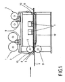
- the width of the aforementioned gap can be changed. This serves to control the amount of coating material which is fed to the surface of a plate. Also, the gap in one embodiment be closed, so as to be able to control the time of delivery. 4. Description of Preferred Embodiments Hereinafter, the invention will be described with reference to FIGS FIG. 1 explained in more detail.
- FIG. 1 shows a device with which a carrier material 6, such as a chip, MDF or HDF plate can be coated in a continuous process.
- the coating materials used are preferably UV- or electron beam-crosslinkable, flowable systems of suitable viscosity.
- a carrier material 6 is supplied and coated with a flowable material 8.
- the coating takes place via a collecting device 5, which adjoins a roller 4.
- a web-shaped material namely a UV-transparent and / or electron-radiation-permeable and radiation-resistant film 3, is guided over the roller 4.
- the film has a smooth, the coating material 8 facing surface when the coating 8 is to have a smooth surface.
- the corresponding surface of the film 3 is structured when the coating 8 according to the invention should have a structured surface.
- the web-shaped material or the film 3 is unrolled from a supply roll or supply roll 1 and finally rolled up again on a roll 2. Between the roller 1 and the roller 4 there are along the transport path for the sheet-like material 3, three further rollers with a relatively small diameter, which serve to guide the sheet-like material.
- the feed throat 13 of small diameter located adjacent to the roll 4, together with the roll 4, causes the sheet material together with the trap 5 to form a cross-sectionally funnel-shaped inlet for coating material 8.
- the coating material 8 for example a lacquer, is suitably brought between the carrier material 6 and the sheet-like material 3 via this funnel shape.
- the funnel-shaped inlet opens into a gap.
- the gap width can be changed to control the supply of coating material.
- roller 4 and the roller 2 there are four further guide rollers with a relatively small diameter, which serve to guide the web-like material from the roller 4 to the roller 2.
- the first guide roller 10 - seen from the roller 4 in the transport direction of the sheet material - causes, together with the roller 4, that the web-like material is guided parallel to the surface of the carrier material 6.
- the film 3 means 7 with which the underlying coating material can be dried and / or cured. These are above all devices for curing with UV light or electron beams.
- a web-shaped smooth or structured material 3 is aligned at the same time from the supply roll 1 both in the longitudinal direction and in the transverse direction and applied synchronously to the carrier material 6 by means of the roller 4 and the catcher 5 on the still liquid coating material.
- the aim of the orientation of the web-shaped material is to synchronize certain points of the carrier material 6 with certain points of the web-like material fitting one above the other.
- the speed of a carrier material or a plate 6 is measured with measuring devices.
- optical measuring devices are used to determine the speed of the carrier material.
- the rotational speed of at least one roller or roller is involved, which is involved in the transport of the sheet-like material.
- the thus obtained information about the transport speed of each plate 6 and transport speed of the sheet material are used for the control.
- the two speeds are thus controlled so that a plate is brought together defined with the web-like material, so as to be able to structure a surface targeted.
- the sheet-like material for example, optical marks, which are detected with optical sensors.
- the transport of the sheet material and / or the transport of the plates 6 are controlled so that a plate is coated in dependence on such an optical marking and the coating is structured in dependence on these optical markings.
- the carrier material with the liquid coating material and the overlying sheet-like material then passes through the curing station 7.
- the liquid coating material 8 is crosslinked and goes into a solid state.
- the surface structure of the web-like material is fixed and imaged in the hardened layer.
- the sheet-like material is removed from the cured solid coating material and wound up again into a roll.
- FIG. 2 shown embodiment provided that a plurality of supply rolls 1 and take-up rolls 2 are present for the web-like material.
- the supply rolls and the Aurwickelrollen can be endlessly connected during production by a device without stop.
- connection is made for reasons of practicality, preferably at speeds up to 120 m / min.
- the respective at rest film receiving station is charged with a roll of web-like material and prepared the automatic connection by a double-sided adhesive tape is glued to the web beginning.
- the beginning of the sheet material is inserted into a gap, which serves to connect. Through this gap at the same time the web-like material is guided, which is currently being unrolled.
- the triggering of the connection is done automatically by electronically detecting the running meters of the roll, from which web-shaped material is unrolled, or sensory Detecting the associated end of a web-shaped material.
- the running web-like material is stored in a dancer device operating as a web store.
- the driven roller is reduced to a speed of about 15 m / min.
- the missing length of the web-like material to the line speed pulls out of the dancer. Accelerate after the connection! the corresponding film roll again up to the maximum speed of, for example, 120 m / min until the dancer roller
- the automatic connection device comprises at least two unwind stations with flap bearings and pneumatic tension shafts.
- the drive of the bends is made by a servo motor, means are available to automatically adjust cars with the films or web-like materials.
- the actual connecting device comprises four pneumatically operated mangle rollers. There are also two cutter blades for cutting the web material after bonding. An automatic braking force regulation of the unwinding rolls is available. This includes dancer rollers, pneumatic proportional linear cylinders with guide and guide rollers and an automatic crack control.
- the carrier material or a plate 6 is first passed through the two superimposed, rotating rollers 4 and 11 passed through and transported. From here, the carrier material 6 reaches a conveyor belt 12, which further transports the carrier material. The web-shaped material or the film 3 and the carrier material 6 are transported at the same speed.
- the distance between the two rollers 4 and 11 can be changed in order to vary the thickness of the coating can.
- the height of the guide roller 10 can be changed in order to influence the thickness of the coating can.
Landscapes
- Engineering & Computer Science (AREA)
- Life Sciences & Earth Sciences (AREA)
- Wood Science & Technology (AREA)
- Physics & Mathematics (AREA)
- Plasma & Fusion (AREA)
- Application Of Or Painting With Fluid Materials (AREA)
- Chemical And Physical Treatments For Wood And The Like (AREA)
- Laminated Bodies (AREA)
- Paints Or Removers (AREA)
- Floor Finish (AREA)
- Dry Formation Of Fiberboard And The Like (AREA)
- Panels For Use In Building Construction (AREA)
Priority Applications (2)
| Application Number | Priority Date | Filing Date | Title |
|---|---|---|---|
| PL07846752T PL2121198T3 (pl) | 2006-11-23 | 2007-11-22 | Sposób bezpośredniego zadrukowywania płyt z tworzyw drzewnych |
| EP07846752A EP2121198B1 (de) | 2006-11-23 | 2007-11-22 | Verfahren zum direktbedrucken von holzwerkstoffplatten |
Applications Claiming Priority (3)
| Application Number | Priority Date | Filing Date | Title |
|---|---|---|---|
| PCT/EP2006/011246 WO2007059967A1 (de) | 2005-11-24 | 2006-11-23 | Beschichtungsanlage mit fliessfähigem beschichtungsmaterial |
| PCT/EP2007/010150 WO2008061765A1 (de) | 2006-11-23 | 2007-11-22 | Verfahren zum direktbedrucken von holzwerkstoffplatten |
| EP07846752A EP2121198B1 (de) | 2006-11-23 | 2007-11-22 | Verfahren zum direktbedrucken von holzwerkstoffplatten |
Publications (2)
| Publication Number | Publication Date |
|---|---|
| EP2121198A1 EP2121198A1 (de) | 2009-11-25 |
| EP2121198B1 true EP2121198B1 (de) | 2011-08-31 |
Family
ID=38983580
Family Applications (3)
| Application Number | Title | Priority Date | Filing Date |
|---|---|---|---|
| EP07846752A Active EP2121198B1 (de) | 2006-11-23 | 2007-11-22 | Verfahren zum direktbedrucken von holzwerkstoffplatten |
| EP07856247A Active EP2094396B1 (de) | 2006-11-23 | 2007-11-23 | Beschichtete holzwerkstoffplatte |
| EP10188389A Active EP2314381B1 (de) | 2006-11-23 | 2007-11-23 | Verfahren zur Beschichtung einer Holzwerkstoffplatte und durch ein solches Verfahren beschichtete Holzwerkstoffplatte |
Family Applications After (2)
| Application Number | Title | Priority Date | Filing Date |
|---|---|---|---|
| EP07856247A Active EP2094396B1 (de) | 2006-11-23 | 2007-11-23 | Beschichtete holzwerkstoffplatte |
| EP10188389A Active EP2314381B1 (de) | 2006-11-23 | 2007-11-23 | Verfahren zur Beschichtung einer Holzwerkstoffplatte und durch ein solches Verfahren beschichtete Holzwerkstoffplatte |
Country Status (9)
| Country | Link |
|---|---|
| EP (3) | EP2121198B1 (pl) |
| AT (3) | ATE522282T1 (pl) |
| DE (1) | DE502007006518D1 (pl) |
| ES (1) | ES2384699T3 (pl) |
| NO (1) | NO20092365L (pl) |
| PL (3) | PL2121198T3 (pl) |
| PT (1) | PT2314381E (pl) |
| UA (2) | UA94133C2 (pl) |
| WO (2) | WO2008061765A1 (pl) |
Cited By (1)
| Publication number | Priority date | Publication date | Assignee | Title |
|---|---|---|---|---|
| DE102020120395A1 (de) | 2020-08-03 | 2022-02-03 | Surteco Gmbh | Verfahren zum Herstellen einer Anbauleiste |
Families Citing this family (18)
| Publication number | Priority date | Publication date | Assignee | Title |
|---|---|---|---|---|
| PT2345545E (pt) * | 2010-01-13 | 2015-04-07 | Kronoplus Technical Ag | Painel leve directamente impresso |
| UA111997C2 (uk) | 2012-04-02 | 2016-07-11 | Кроноплюс Текнікал Аг | Панель з покриттям, нанесеним методом прямого друку |
| CA2876378C (en) | 2012-06-13 | 2019-09-24 | Kronoplus Technical Ag | Panel with decor layer and method for imprinting plates |
| UA111803C2 (uk) * | 2012-10-05 | 2016-06-10 | Кроноплюс Текнікал Аг | Підлогова панель для зовнішнього застосування |
| DE102012113000B4 (de) * | 2012-12-21 | 2017-12-21 | Gebrüder Dorfner GmbH & Co. Kaolin- und Kristallquarzsand-Werke KG | Verbundwerkstoff, Verfahren zu dessen Herstellung und dessen Verwendung |
| WO2014202144A1 (de) * | 2013-06-20 | 2014-12-24 | Kronoplus Technical Ag | Verfahren zur herstellung eines direkt bedruckten paneels |
| CA2915134C (en) * | 2013-06-20 | 2019-03-12 | Kronoplus Technical Ag | Direct imprinted panel with two-layer-structure |
| UA117159C2 (uk) | 2014-01-14 | 2018-06-25 | Кроноплюс Текнікал Аг | Багатошарова будівельна плита для внутрішнього та зовнішнього застосування |
| EP3323628B1 (de) * | 2014-02-25 | 2022-06-15 | Akzenta Paneele + Profile GmbH | Verfahren zum herstellen von dekorpaneelen |
| EP2942208A1 (de) | 2014-05-09 | 2015-11-11 | Akzenta Paneele + Profile GmbH | Verfahren zur Herstellung eines dekorierten Wand- oder Bodenpaneels |
| PT3132945T (pt) | 2015-08-19 | 2019-10-25 | Akzenta Paneele Profile Gmbh | Método para produzir um painel decorado de parede ou piso. |
| PT3246175T (pt) | 2016-05-20 | 2018-10-22 | Flooring Technologies Ltd | Processo para a produção de uma placa de derivados de madeira resistente à abrasão e linha de produção para a mesma |
| HRP20220826T1 (hr) | 2017-02-03 | 2022-10-14 | Xylo Technologies Ag | Panel od pvc plastike |
| EP3385046A1 (en) | 2017-04-07 | 2018-10-10 | Omya International AG | In-line coated decorative wood-based boards |
| EA201992222A1 (ru) | 2017-09-28 | 2020-02-10 | Юнилин, Бвба | Плита и способ изготовления плиты |
| PT3480030T (pt) * | 2017-11-06 | 2020-07-21 | Flooring Technologies Ltd | Processo para o fabrico de um painel de derivado da madeira resistente ao desgaste e linha de produção para o mesmo |
| PL3686028T3 (pl) | 2019-01-22 | 2021-10-25 | Flooring Technologies Ltd. | Sposób wytwarzania odpornej na ścieranie płyty drewnopochodnej |
| CN110696516A (zh) * | 2019-10-12 | 2020-01-17 | 浙江晶通塑胶有限公司 | 一种数码印刷地板的加工工艺 |
Family Cites Families (8)
| Publication number | Priority date | Publication date | Assignee | Title |
|---|---|---|---|---|
| CH627132A5 (pl) * | 1979-01-23 | 1981-12-31 | Sicpa Holding Sa | |
| DE3802797A1 (de) * | 1988-01-30 | 1989-08-10 | Guenther Dr Schwarz | Verfahren und vorrichtung zum herstellen schnellhaertender ueberzuege auf traegerkoerpern |
| WO1999061168A1 (en) * | 1998-05-28 | 1999-12-02 | Adkin Services Limited | Method for curing paints by means of uv rays |
| DE102004031547A1 (de) * | 2003-08-20 | 2005-03-17 | Kronospan Ag | Holzwerkstoffplatte mit einer Oberflächenbeschichtung und Verfahren zur Herstellung hierfür |
| DE102004043355B4 (de) * | 2004-09-08 | 2006-09-21 | Kronotec Ag | Imprägnat |
| EP2218520B1 (de) * | 2004-10-05 | 2013-06-12 | Fritz Egger GmbH & Co. OG | Verfahren und Vorrichtung zur Herstellung einer strukturierten Oberfläche |
| RU2404861C2 (ru) * | 2005-10-10 | 2010-11-27 | Кроноспан Текникал Компани Лтд. | Износостойкая плита с декоративной поверхностью |
| WO2007059805A1 (de) * | 2005-11-24 | 2007-05-31 | Kronospan Technical Company Ltd. | BESCHICHTUNGSANLAGE MIT FLIEßFÄHIGEM BESCHICHTUNGSMATERIAL FÜR GLATTE ODER STRUKTURIERTE OBERFLÄCHEN |
-
2007
- 2007-11-22 WO PCT/EP2007/010150 patent/WO2008061765A1/de active Application Filing
- 2007-11-22 UA UAA200906533A patent/UA94133C2/ru unknown
- 2007-11-22 EP EP07846752A patent/EP2121198B1/de active Active
- 2007-11-22 PL PL07846752T patent/PL2121198T3/pl unknown
- 2007-11-22 AT AT07846752T patent/ATE522282T1/de active
- 2007-11-23 PL PL07856247T patent/PL2094396T3/pl unknown
- 2007-11-23 DE DE502007006518T patent/DE502007006518D1/de active Active
- 2007-11-23 EP EP07856247A patent/EP2094396B1/de active Active
- 2007-11-23 ES ES10188389T patent/ES2384699T3/es active Active
- 2007-11-23 WO PCT/EP2007/010215 patent/WO2008061791A1/de active Application Filing
- 2007-11-23 PL PL10188389T patent/PL2314381T3/pl unknown
- 2007-11-23 PT PT10188389T patent/PT2314381E/pt unknown
- 2007-11-23 AT AT07856247T patent/ATE498459T1/de active
- 2007-11-23 AT AT10188389T patent/ATE550108T1/de active
- 2007-11-23 UA UAA200906531A patent/UA96464C2/ru unknown
- 2007-11-23 EP EP10188389A patent/EP2314381B1/de active Active
-
2009
- 2009-06-19 NO NO20092365A patent/NO20092365L/no not_active Application Discontinuation
Cited By (2)
| Publication number | Priority date | Publication date | Assignee | Title |
|---|---|---|---|---|
| DE102020120395A1 (de) | 2020-08-03 | 2022-02-03 | Surteco Gmbh | Verfahren zum Herstellen einer Anbauleiste |
| WO2022028758A1 (de) | 2020-08-03 | 2022-02-10 | Surteco Gmbh | Verfahren zum herstellen einer anbauleiste |
Also Published As
| Publication number | Publication date |
|---|---|
| NO20092365L (no) | 2009-08-19 |
| WO2008061791A1 (de) | 2008-05-29 |
| DE502007006518D1 (de) | 2011-03-31 |
| EP2314381A1 (de) | 2011-04-27 |
| PL2314381T3 (pl) | 2012-08-31 |
| EP2094396A1 (de) | 2009-09-02 |
| UA96464C2 (ru) | 2011-11-10 |
| EP2314381B1 (de) | 2012-03-21 |
| PL2094396T3 (pl) | 2011-07-29 |
| EP2121198A1 (de) | 2009-11-25 |
| ATE522282T1 (de) | 2011-09-15 |
| ATE498459T1 (de) | 2011-03-15 |
| PT2314381E (pt) | 2012-06-15 |
| EP2094396B1 (de) | 2011-02-16 |
| ATE550108T1 (de) | 2012-04-15 |
| PL2121198T3 (pl) | 2012-01-31 |
| WO2008061765A1 (de) | 2008-05-29 |
| ES2384699T3 (es) | 2012-07-11 |
| UA94133C2 (ru) | 2011-04-11 |
Similar Documents
| Publication | Publication Date | Title |
|---|---|---|
| EP2121198B1 (de) | Verfahren zum direktbedrucken von holzwerkstoffplatten | |
| EP2019735B2 (de) | Beschichtungsanlage mit fliessfähigem beschichtungsmaterial | |
| EP3666525B1 (de) | Verfahren zur erzeugung einer strukturierten oberfläche | |
| EP3403846B1 (de) | Verfahren zur herstellung eines dekorierten wand- oder bodenpaneels | |
| EP1937476B1 (de) | Abriebfeste platten mit dekorativer oberfläche | |
| EP2829415A1 (de) | Verfahren zur Herstellung eines dekorierten Wand-und Bodenpaneels | |
| EP1923211B1 (de) | Beschichtungsmaterialien sowie verfahren zum herstellen solcher beschichtungsmaterialien | |
| DE202005015978U1 (de) | Abriebfeste Platten mit dekorativer Oberfläche | |
| WO2014072179A1 (de) | Verfahren zur herstellung eines dekorierten wand- oder bodenpaneels | |
| EP2992142B1 (de) | Verfahren zur herstellung einer bedruckbaren ein- oder mehrschichtigen materialbahn sowie eine zugehörige anlage zur herstellung einer derartigen materialbahn | |
| EP1245382A2 (de) | Laminatpaneel für Fussböden | |
| EP2223800B1 (de) | Dekorprodukt, Verfahren zum Herstellen eines Dekorprodukts und Verwendung eines Dekorprodukts zum Herstellen einer dekorierten Trägerfläche | |
| EP3351682B1 (de) | Schichtstoff zum beschichten eines plattenförmigen holzwerkstoffs | |
| EP2179863A1 (de) | Verfahren zum Veredeln einer Trägerplatte, insbesondere einer Holz- oder Holzwerkstoffplatte | |
| EP3108970B1 (de) | Verfahren zur herstellung eines lackierten, dekorativen laminates | |
| EP3088204B1 (de) | Verfahren zur herstellung eines dekorierten wand- oder bodenpaneels | |
| WO2013167533A1 (de) | Verfahren zur herstellung eines dekorierten blattes und dessen verwendung | |
| US20170113248A1 (en) | Method for printing directly onto boards of wood-based material | |
| EP3597312B1 (de) | Verfahren zur herstellung einer mit einer bedruckten oberfläche versehenen osb | |
| EP2179864B1 (de) | Verfahren zum Veredeln einer Trägerplatte | |
| EP2419280B1 (de) | Verfahren zum herstellen einer bedruckbaren bauplatte |
Legal Events
| Date | Code | Title | Description |
|---|---|---|---|
| PUAI | Public reference made under article 153(3) epc to a published international application that has entered the european phase |
Free format text: ORIGINAL CODE: 0009012 |
|
| 17P | Request for examination filed |
Effective date: 20090623 |
|
| AK | Designated contracting states |
Kind code of ref document: A1 Designated state(s): AT BE BG CH CY CZ DE DK EE ES FI FR GB GR HU IE IS IT LI LT LU LV MC MT NL PL PT RO SE SI SK TR |
|
| DAX | Request for extension of the european patent (deleted) | ||
| RAP1 | Party data changed (applicant data changed or rights of an application transferred) |
Owner name: KRONOPLUS TECHNICAL AG |
|
| GRAP | Despatch of communication of intention to grant a patent |
Free format text: ORIGINAL CODE: EPIDOSNIGR1 |
|
| GRAS | Grant fee paid |
Free format text: ORIGINAL CODE: EPIDOSNIGR3 |
|
| GRAA | (expected) grant |
Free format text: ORIGINAL CODE: 0009210 |
|
| AK | Designated contracting states |
Kind code of ref document: B1 Designated state(s): AT BE BG CH CY CZ DE DK EE ES FI FR GB GR HU IE IS IT LI LT LU LV MC MT NL PL PT RO SE SI SK TR |
|
| REG | Reference to a national code |
Ref country code: CH Ref legal event code: EP Ref country code: GB Ref legal event code: FG4D Free format text: NOT ENGLISH |
|
| REG | Reference to a national code |
Ref country code: IE Ref legal event code: FG4D Free format text: LANGUAGE OF EP DOCUMENT: GERMAN |
|
| REG | Reference to a national code |
Ref country code: DE Ref legal event code: R096 Ref document number: 502007008052 Country of ref document: DE Effective date: 20111027 |
|
| REG | Reference to a national code |
Ref country code: SE Ref legal event code: TRGR |
|
| REG | Reference to a national code |
Ref country code: SE Ref legal event code: RPOT |
|
| REG | Reference to a national code |
Ref country code: NL Ref legal event code: VDEP Effective date: 20110831 |
|
| LTIE | Lt: invalidation of european patent or patent extension |
Effective date: 20110831 |
|
| PG25 | Lapsed in a contracting state [announced via postgrant information from national office to epo] |
Ref country code: IS Free format text: LAPSE BECAUSE OF FAILURE TO SUBMIT A TRANSLATION OF THE DESCRIPTION OR TO PAY THE FEE WITHIN THE PRESCRIBED TIME-LIMIT Effective date: 20111231 Ref country code: NL Free format text: LAPSE BECAUSE OF FAILURE TO SUBMIT A TRANSLATION OF THE DESCRIPTION OR TO PAY THE FEE WITHIN THE PRESCRIBED TIME-LIMIT Effective date: 20110831 Ref country code: LT Free format text: LAPSE BECAUSE OF FAILURE TO SUBMIT A TRANSLATION OF THE DESCRIPTION OR TO PAY THE FEE WITHIN THE PRESCRIBED TIME-LIMIT Effective date: 20110831 Ref country code: FI Free format text: LAPSE BECAUSE OF FAILURE TO SUBMIT A TRANSLATION OF THE DESCRIPTION OR TO PAY THE FEE WITHIN THE PRESCRIBED TIME-LIMIT Effective date: 20110831 |
|
| REG | Reference to a national code |
Ref country code: PL Ref legal event code: T3 |
|
| PG25 | Lapsed in a contracting state [announced via postgrant information from national office to epo] |
Ref country code: SI Free format text: LAPSE BECAUSE OF FAILURE TO SUBMIT A TRANSLATION OF THE DESCRIPTION OR TO PAY THE FEE WITHIN THE PRESCRIBED TIME-LIMIT Effective date: 20110831 Ref country code: CY Free format text: LAPSE BECAUSE OF FAILURE TO SUBMIT A TRANSLATION OF THE DESCRIPTION OR TO PAY THE FEE WITHIN THE PRESCRIBED TIME-LIMIT Effective date: 20110831 Ref country code: GR Free format text: LAPSE BECAUSE OF FAILURE TO SUBMIT A TRANSLATION OF THE DESCRIPTION OR TO PAY THE FEE WITHIN THE PRESCRIBED TIME-LIMIT Effective date: 20111201 Ref country code: LV Free format text: LAPSE BECAUSE OF FAILURE TO SUBMIT A TRANSLATION OF THE DESCRIPTION OR TO PAY THE FEE WITHIN THE PRESCRIBED TIME-LIMIT Effective date: 20110831 |
|
| REG | Reference to a national code |
Ref country code: IE Ref legal event code: FD4D |
|
| PG25 | Lapsed in a contracting state [announced via postgrant information from national office to epo] |
Ref country code: SK Free format text: LAPSE BECAUSE OF FAILURE TO SUBMIT A TRANSLATION OF THE DESCRIPTION OR TO PAY THE FEE WITHIN THE PRESCRIBED TIME-LIMIT Effective date: 20110831 Ref country code: CZ Free format text: LAPSE BECAUSE OF FAILURE TO SUBMIT A TRANSLATION OF THE DESCRIPTION OR TO PAY THE FEE WITHIN THE PRESCRIBED TIME-LIMIT Effective date: 20110831 Ref country code: IE Free format text: LAPSE BECAUSE OF FAILURE TO SUBMIT A TRANSLATION OF THE DESCRIPTION OR TO PAY THE FEE WITHIN THE PRESCRIBED TIME-LIMIT Effective date: 20110831 |
|
| PG25 | Lapsed in a contracting state [announced via postgrant information from national office to epo] |
Ref country code: PT Free format text: LAPSE BECAUSE OF FAILURE TO SUBMIT A TRANSLATION OF THE DESCRIPTION OR TO PAY THE FEE WITHIN THE PRESCRIBED TIME-LIMIT Effective date: 20120102 Ref country code: RO Free format text: LAPSE BECAUSE OF FAILURE TO SUBMIT A TRANSLATION OF THE DESCRIPTION OR TO PAY THE FEE WITHIN THE PRESCRIBED TIME-LIMIT Effective date: 20110831 Ref country code: EE Free format text: LAPSE BECAUSE OF FAILURE TO SUBMIT A TRANSLATION OF THE DESCRIPTION OR TO PAY THE FEE WITHIN THE PRESCRIBED TIME-LIMIT Effective date: 20110831 |
|
| PG25 | Lapsed in a contracting state [announced via postgrant information from national office to epo] |
Ref country code: MC Free format text: LAPSE BECAUSE OF NON-PAYMENT OF DUE FEES Effective date: 20111130 Ref country code: DK Free format text: LAPSE BECAUSE OF FAILURE TO SUBMIT A TRANSLATION OF THE DESCRIPTION OR TO PAY THE FEE WITHIN THE PRESCRIBED TIME-LIMIT Effective date: 20110831 |
|
| REG | Reference to a national code |
Ref country code: CH Ref legal event code: PL |
|
| PLBE | No opposition filed within time limit |
Free format text: ORIGINAL CODE: 0009261 |
|
| STAA | Information on the status of an ep patent application or granted ep patent |
Free format text: STATUS: NO OPPOSITION FILED WITHIN TIME LIMIT |
|
| PG25 | Lapsed in a contracting state [announced via postgrant information from national office to epo] |
Ref country code: LI Free format text: LAPSE BECAUSE OF NON-PAYMENT OF DUE FEES Effective date: 20111130 Ref country code: CH Free format text: LAPSE BECAUSE OF NON-PAYMENT OF DUE FEES Effective date: 20111130 |
|
| 26N | No opposition filed |
Effective date: 20120601 |
|
| REG | Reference to a national code |
Ref country code: DE Ref legal event code: R097 Ref document number: 502007008052 Country of ref document: DE Effective date: 20120601 |
|
| PG25 | Lapsed in a contracting state [announced via postgrant information from national office to epo] |
Ref country code: MT Free format text: LAPSE BECAUSE OF FAILURE TO SUBMIT A TRANSLATION OF THE DESCRIPTION OR TO PAY THE FEE WITHIN THE PRESCRIBED TIME-LIMIT Effective date: 20110831 |
|
| PG25 | Lapsed in a contracting state [announced via postgrant information from national office to epo] |
Ref country code: ES Free format text: LAPSE BECAUSE OF FAILURE TO SUBMIT A TRANSLATION OF THE DESCRIPTION OR TO PAY THE FEE WITHIN THE PRESCRIBED TIME-LIMIT Effective date: 20111211 |
|
| PG25 | Lapsed in a contracting state [announced via postgrant information from national office to epo] |
Ref country code: LU Free format text: LAPSE BECAUSE OF NON-PAYMENT OF DUE FEES Effective date: 20111122 |
|
| PG25 | Lapsed in a contracting state [announced via postgrant information from national office to epo] |
Ref country code: BG Free format text: LAPSE BECAUSE OF FAILURE TO SUBMIT A TRANSLATION OF THE DESCRIPTION OR TO PAY THE FEE WITHIN THE PRESCRIBED TIME-LIMIT Effective date: 20111130 |
|
| PG25 | Lapsed in a contracting state [announced via postgrant information from national office to epo] |
Ref country code: HU Free format text: LAPSE BECAUSE OF FAILURE TO SUBMIT A TRANSLATION OF THE DESCRIPTION OR TO PAY THE FEE WITHIN THE PRESCRIBED TIME-LIMIT Effective date: 20110831 |
|
| REG | Reference to a national code |
Ref country code: FR Ref legal event code: PLFP Year of fee payment: 9 |
|
| REG | Reference to a national code |
Ref country code: FR Ref legal event code: PLFP Year of fee payment: 10 |
|
| REG | Reference to a national code |
Ref country code: FR Ref legal event code: PLFP Year of fee payment: 11 |
|
| REG | Reference to a national code |
Ref country code: DE Ref legal event code: R082 Ref document number: 502007008052 Country of ref document: DE Representative=s name: BARDEHLE PAGENBERG PARTNERSCHAFT MBB PATENTANW, DE Ref country code: DE Ref legal event code: R081 Ref document number: 502007008052 Country of ref document: DE Owner name: XYLO TECHNOLOGIES AG, CH Free format text: FORMER OWNER: KRONOPLUS TECHNICAL AG, NIEDERTEUFEN, CH |
|
| REG | Reference to a national code |
Ref country code: BE Ref legal event code: HC Owner name: XYLO TECHNOLOGIES AG; CH Free format text: DETAILS ASSIGNMENT: CHANGE OF OWNER(S), CHANGEMENT DE NOM DU PROPRIETAIRE; FORMER OWNER NAME: KRONOPLUS TECHNICAL AG Effective date: 20181029 |
|
| REG | Reference to a national code |
Ref country code: AT Ref legal event code: HC Ref document number: 522282 Country of ref document: AT Kind code of ref document: T Owner name: XYLO TECHNOLOGIES AG, CH Effective date: 20190129 |
|
| REG | Reference to a national code |
Ref country code: DE Ref legal event code: R081 Ref document number: 502007008052 Country of ref document: DE Owner name: LIGNUM TECHNOLOGIES AG, CH Free format text: FORMER OWNER: XYLO TECHNOLOGIES AG, TEUFEN, CH |
|
| REG | Reference to a national code |
Ref country code: BE Ref legal event code: HC Owner name: LIGNUM TECHNOLOGIES AG; CH Free format text: DETAILS ASSIGNMENT: CHANGE OF OWNER(S), CHANGE OF OWNER(S) NAME; FORMER OWNER NAME: XYLO TECHNOLOGIES AG Effective date: 20231113 |
|
| PGFP | Annual fee paid to national office [announced via postgrant information from national office to epo] |
Ref country code: GB Payment date: 20231123 Year of fee payment: 17 |
|
| PGFP | Annual fee paid to national office [announced via postgrant information from national office to epo] |
Ref country code: TR Payment date: 20231120 Year of fee payment: 17 Ref country code: SE Payment date: 20231120 Year of fee payment: 17 Ref country code: IT Payment date: 20231124 Year of fee payment: 17 Ref country code: FR Payment date: 20231120 Year of fee payment: 17 Ref country code: DE Payment date: 20231121 Year of fee payment: 17 Ref country code: AT Payment date: 20231121 Year of fee payment: 17 |
|
| PGFP | Annual fee paid to national office [announced via postgrant information from national office to epo] |
Ref country code: PL Payment date: 20231109 Year of fee payment: 17 Ref country code: BE Payment date: 20231120 Year of fee payment: 17 |
|
| REG | Reference to a national code |
Ref country code: AT Ref legal event code: HC Ref document number: 522282 Country of ref document: AT Kind code of ref document: T Owner name: LIGNUM TECHNOLOGIES AG, CH Effective date: 20240206 |