EP2121198B1 - Method for printing directly onto boards of wood-based material - Google Patents
Method for printing directly onto boards of wood-based material Download PDFInfo
- Publication number
- EP2121198B1 EP2121198B1 EP07846752A EP07846752A EP2121198B1 EP 2121198 B1 EP2121198 B1 EP 2121198B1 EP 07846752 A EP07846752 A EP 07846752A EP 07846752 A EP07846752 A EP 07846752A EP 2121198 B1 EP2121198 B1 EP 2121198B1
- Authority
- EP
- European Patent Office
- Prior art keywords
- layer
- plastic material
- board
- coating
- web
- Prior art date
- Legal status (The legal status is an assumption and is not a legal conclusion. Google has not performed a legal analysis and makes no representation as to the accuracy of the status listed.)
- Active
Links
- 238000000034 method Methods 0.000 title claims abstract description 37
- 239000000463 material Substances 0.000 title claims description 155
- 239000002023 wood Substances 0.000 title claims description 39
- 238000000576 coating method Methods 0.000 claims abstract description 61
- 239000011248 coating agent Substances 0.000 claims abstract description 59
- 238000001035 drying Methods 0.000 claims abstract description 9
- 239000004033 plastic Substances 0.000 claims description 60
- 229920003023 plastic Polymers 0.000 claims description 60
- 239000002245 particle Substances 0.000 claims description 35
- 238000005299 abrasion Methods 0.000 claims description 27
- NIXOWILDQLNWCW-UHFFFAOYSA-M Acrylate Chemical compound [O-]C(=O)C=C NIXOWILDQLNWCW-UHFFFAOYSA-M 0.000 claims description 12
- 229910052593 corundum Inorganic materials 0.000 claims description 9
- 239000010431 corundum Substances 0.000 claims description 9
- 230000009969 flowable effect Effects 0.000 claims description 9
- 238000006116 polymerization reaction Methods 0.000 claims description 6
- 230000005855 radiation Effects 0.000 claims description 6
- 230000000694 effects Effects 0.000 claims description 3
- 238000005520 cutting process Methods 0.000 claims description 2
- 239000010410 layer Substances 0.000 claims 19
- 239000002356 single layer Substances 0.000 claims 2
- 238000004049 embossing Methods 0.000 claims 1
- 239000002184 metal Substances 0.000 claims 1
- 239000010902 straw Substances 0.000 claims 1
- -1 tree needles Substances 0.000 claims 1
- 239000007788 liquid Substances 0.000 abstract description 12
- 230000008569 process Effects 0.000 abstract description 5
- 238000010894 electron beam technology Methods 0.000 abstract description 3
- NIXOWILDQLNWCW-UHFFFAOYSA-N acrylic acid group Chemical group C(C=C)(=O)O NIXOWILDQLNWCW-UHFFFAOYSA-N 0.000 abstract description 2
- 239000011093 chipboard Substances 0.000 abstract description 2
- 239000003795 chemical substances by application Substances 0.000 abstract 1
- 239000011094 fiberboard Substances 0.000 abstract 1
- 230000032258 transport Effects 0.000 description 15
- 239000012876 carrier material Substances 0.000 description 13
- 239000010408 film Substances 0.000 description 12
- 239000007787 solid Substances 0.000 description 8
- 239000004922 lacquer Substances 0.000 description 6
- 238000004519 manufacturing process Methods 0.000 description 6
- 230000003287 optical effect Effects 0.000 description 6
- 239000003973 paint Substances 0.000 description 6
- 238000006243 chemical reaction Methods 0.000 description 4
- 238000005034 decoration Methods 0.000 description 3
- 230000007717 exclusion Effects 0.000 description 3
- 239000000123 paper Substances 0.000 description 3
- 239000010409 thin film Substances 0.000 description 3
- 239000003082 abrasive agent Substances 0.000 description 2
- 125000005396 acrylic acid ester group Chemical group 0.000 description 2
- 238000004132 cross linking Methods 0.000 description 2
- 230000006872 improvement Effects 0.000 description 2
- 239000000203 mixture Substances 0.000 description 2
- 238000012805 post-processing Methods 0.000 description 2
- 239000011347 resin Substances 0.000 description 2
- 229920005989 resin Polymers 0.000 description 2
- 241000894007 species Species 0.000 description 2
- 239000000126 substance Substances 0.000 description 2
- 239000002966 varnish Substances 0.000 description 2
- SMZOUWXMTYCWNB-UHFFFAOYSA-N 2-(2-methoxy-5-methylphenyl)ethanamine Chemical compound COC1=CC=C(C)C=C1CCN SMZOUWXMTYCWNB-UHFFFAOYSA-N 0.000 description 1
- 239000004925 Acrylic resin Substances 0.000 description 1
- 229920000178 Acrylic resin Polymers 0.000 description 1
- 244000025254 Cannabis sativa Species 0.000 description 1
- 235000012766 Cannabis sativa ssp. sativa var. sativa Nutrition 0.000 description 1
- 235000012765 Cannabis sativa ssp. sativa var. spontanea Nutrition 0.000 description 1
- 239000002390 adhesive tape Substances 0.000 description 1
- 230000015572 biosynthetic process Effects 0.000 description 1
- 235000009120 camo Nutrition 0.000 description 1
- 235000005607 chanvre indien Nutrition 0.000 description 1
- 150000001875 compounds Chemical class 0.000 description 1
- 238000010924 continuous production Methods 0.000 description 1
- 239000007799 cork Substances 0.000 description 1
- 238000000354 decomposition reaction Methods 0.000 description 1
- 239000006185 dispersion Substances 0.000 description 1
- 230000005284 excitation Effects 0.000 description 1
- 238000007306 functionalization reaction Methods 0.000 description 1
- 239000011487 hemp Substances 0.000 description 1
- 238000005304 joining Methods 0.000 description 1
- 239000011344 liquid material Substances 0.000 description 1
- 239000002923 metal particle Substances 0.000 description 1
- 238000003801 milling Methods 0.000 description 1
- 229930014626 natural product Natural products 0.000 description 1
- 230000006855 networking Effects 0.000 description 1
- 238000010422 painting Methods 0.000 description 1
- 238000000059 patterning Methods 0.000 description 1
- 238000006068 polycondensation reaction Methods 0.000 description 1
- 229920000728 polyester Polymers 0.000 description 1
- 229920000642 polymer Polymers 0.000 description 1
- 229920002635 polyurethane Polymers 0.000 description 1
- 239000004814 polyurethane Substances 0.000 description 1
- 230000037452 priming Effects 0.000 description 1
- 230000001953 sensory effect Effects 0.000 description 1
- 230000035939 shock Effects 0.000 description 1
- 229920003002 synthetic resin Polymers 0.000 description 1
- 239000000057 synthetic resin Substances 0.000 description 1
- 210000002268 wool Anatomy 0.000 description 1
Images

Classifications
-
- B—PERFORMING OPERATIONS; TRANSPORTING
- B05—SPRAYING OR ATOMISING IN GENERAL; APPLYING FLUENT MATERIALS TO SURFACES, IN GENERAL
- B05D—PROCESSES FOR APPLYING FLUENT MATERIALS TO SURFACES, IN GENERAL
- B05D7/00—Processes, other than flocking, specially adapted for applying liquids or other fluent materials to particular surfaces or for applying particular liquids or other fluent materials
- B05D7/06—Processes, other than flocking, specially adapted for applying liquids or other fluent materials to particular surfaces or for applying particular liquids or other fluent materials to wood
-
- B—PERFORMING OPERATIONS; TRANSPORTING
- B05—SPRAYING OR ATOMISING IN GENERAL; APPLYING FLUENT MATERIALS TO SURFACES, IN GENERAL
- B05D—PROCESSES FOR APPLYING FLUENT MATERIALS TO SURFACES, IN GENERAL
- B05D1/00—Processes for applying liquids or other fluent materials
- B05D1/40—Distributing applied liquids or other fluent materials by members moving relatively to surface
-
- B—PERFORMING OPERATIONS; TRANSPORTING
- B05—SPRAYING OR ATOMISING IN GENERAL; APPLYING FLUENT MATERIALS TO SURFACES, IN GENERAL
- B05D—PROCESSES FOR APPLYING FLUENT MATERIALS TO SURFACES, IN GENERAL
- B05D3/00—Pretreatment of surfaces to which liquids or other fluent materials are to be applied; After-treatment of applied coatings, e.g. intermediate treating of an applied coating preparatory to subsequent applications of liquids or other fluent materials
- B05D3/06—Pretreatment of surfaces to which liquids or other fluent materials are to be applied; After-treatment of applied coatings, e.g. intermediate treating of an applied coating preparatory to subsequent applications of liquids or other fluent materials by exposure to radiation
- B05D3/061—Pretreatment of surfaces to which liquids or other fluent materials are to be applied; After-treatment of applied coatings, e.g. intermediate treating of an applied coating preparatory to subsequent applications of liquids or other fluent materials by exposure to radiation using U.V.
- B05D3/065—After-treatment
- B05D3/067—Curing or cross-linking the coating
-
- B—PERFORMING OPERATIONS; TRANSPORTING
- B05—SPRAYING OR ATOMISING IN GENERAL; APPLYING FLUENT MATERIALS TO SURFACES, IN GENERAL
- B05D—PROCESSES FOR APPLYING FLUENT MATERIALS TO SURFACES, IN GENERAL
- B05D5/00—Processes for applying liquids or other fluent materials to surfaces to obtain special surface effects, finishes or structures
- B05D5/06—Processes for applying liquids or other fluent materials to surfaces to obtain special surface effects, finishes or structures to obtain multicolour or other optical effects
-
- B—PERFORMING OPERATIONS; TRANSPORTING
- B05—SPRAYING OR ATOMISING IN GENERAL; APPLYING FLUENT MATERIALS TO SURFACES, IN GENERAL
- B05D—PROCESSES FOR APPLYING FLUENT MATERIALS TO SURFACES, IN GENERAL
- B05D5/00—Processes for applying liquids or other fluent materials to surfaces to obtain special surface effects, finishes or structures
- B05D5/02—Processes for applying liquids or other fluent materials to surfaces to obtain special surface effects, finishes or structures to obtain a matt or rough surface
Definitions
- the invention relates to a method for the coating of boards, in particular of wood-based panels for the production of floor panels, with a flowable coating material.
- Laminate panels essentially consist of an approx. 6 to 8 mm thick base plate made of MDF or HDF material, to which a decor paper layer is glued. The decor paper layer is impregnated with a resin and is usually further provided with abrasion-resistant particles.
- the application of pressure and heat hardens the resin and creates an extremely abrasion-resistant and decorative surface.
- new methods have been developed to print wood-based panels, such as MDF or HDF, directly with a plastic material, ie without the use of decorative paper.
- the MDF board for example, is sanded off and primed.
- a colored decor is printed on this primer, for example a wood decor.
- a plurality of very thin material layers are applied, wherein the individual material layers each cured before applying the next layer.
- the material layers are, for example, a plurality of, essentially transparent lacquer layers of a hardenable plastic.
- the resulting overall layer thus has a layered structure.
- the individual layers Between the individual layers arise interfaces in which no good networking takes place.
- the individual layers usually have a thickness of 10 to 15 .mu.m and usually 5 to 7 layers are applied one above the other, resulting in a total thickness of the thin-layer system or layer stack of about 50-105 .mu.m.
- wood-based panel this includes all wood-based materials in the broadest sense, ie panels that are made of wood, or that are made using wood materials. These include, but are not limited to, OSB panels, MDF or HDF, chipboard, solid and solid wood, veneered and prefinished parquet and others.
- this invention relates to improved wood-based panels for use as a floor covering or wall or ceiling covering.
- U1 is a device for the coating of plates in the run out.
- Several plates are arranged on a conveyor belt, which are fed one after the other, inter alia coating stations.
- Such a coating station comprises an applicator roll, with which a lacquer is applied to a plate.
- an applicator roll with which a lacquer is applied to a plate.
- the applicator roll may include a textured surface to pattern lacquer on the surface of a plate.
- the coatings consist for example of liquid plastics or synthetic resins to be cured by a brief thermal shock to a film.
- a device which comprises transport means for the transport of plates.
- the device also comprises a supply device with which coating material can be brought onto the plate surface. Subsequent to the feeding device, means for drying and / or curing the coating material are provided above the plate.
- the device comprises means to be able to pass a material web between the transport means for the transport of plates and the means for drying and / or curing.
- the surface of the coating material can according to the invention be provided with a structure without having to exert high pressure. Since the coating material is dried and / or cured in this state, it is thus possible to coat a plate with a structured surface, without this being the case in the publication DE 20 2004 018 710 U1 known prior art either have to use a press or a complex printing unit. Also, a multi-step coating can thus be uniformly dried and / or cured in one operation. Above all, it is possible that a chemical network extends through the entire structure of the layer, resulting in a particularly stable coating.
- drying and / or curing under exclusion of air is possible. Drying and / or curing under exclusion of air is frequently desired, for example in order to achieve particularly high crosslinking in the case of curing of a varnish with UV light, ie a particularly high conversion of double bonds within the varnish. In the case of curing with electron beams, an air seal is usually required.
- the invention relates to a novel process for coating a wood-based panel, in particular a particleboard, MDF or HDF board, with a flowable plastic material.
- the method relates to the production of panels, such as the manufacture of floor panels.
- a thick layer of at least 30 .mu.m of a plastic material is applied to the wood-based panel in a single step.
- the plastic material is preferably transparent at least after drying or curing.
- the layer is preferably applied in a single operation in a thickness of 30 to 150 microns, more preferably in a thickness of 80 to 110 microns and most preferably in a thickness applied by about 95 microns.
- the layer of plastic material is cured.
- abrasion-resistant particles such as, for example, larger corundum particles
- the individual thin layers only have a thickness of 10 to 15 .mu.m, and which are cured one after the other, in fact only relatively small particles can be used, since the particles are preferably incorporated as far as possible in the layers should be.
- the flowable plastic material is preferably an acrylate system.
- an acrylate system is meant, for example, a polymerizable mixture of double bond-containing mono-, di- and polyfunctional acrylic acid-based compounds. Typical representatives are for example Dipropylenglycoldiacrylat, 1,6-Hexandioldiacrylat, polyurethane acrylic acid ester, polyester acrylic acid ester as they are available in the production program of the company BASF under the trade name Laromer TM types on the market.
- the wood-based panel is preferably provided with a colored decorative print prior to coating with the flowable plastic material, e.g. with a wood decor.
- the plastic material is applied via the decor pressure and is preferably as transparent as possible. The process can be carried out, for example, as follows:
- the carrier plate such as an MDF plate
- a primer is applied and preferably applied a primer.
- the decoration is printed on the primer or the primer.
- a further primer is applied, which is preferably a suitable primer for the following layer of plastic material.
- This primer is preferably applied in an amount of up to 10 g / m 2 , more preferably of about 5 g / m 2 .
- a single thick layer of an acrylate system is applied to the primer by, for example, roller application. This is preferably done in an amount of up to 100 g / m 2 , more preferably of about 65 g / m 2 .
- the plastic material is preferably a polymerizable acrylate system.
- the plastic material such as the polymerizable acrylate system, a UV-curable plastic.
- the UV radiation serves to start the polymerization. Since the polymerization can be stopped at any time, it is thus possible in the single thick layer, e.g. May be 95 microns, a Vernetzungsgradienten and thus produce a cure gradients.
- the curing gradient is generated over a single, over the entire layer thickness occurring polymerization with the highest possible conversion. This is in contrast to painting with many thin films, which are applied layer by layer and then "gelled” by radiation, i. it is prematurely aborted the reaction. Thus, over the entire cross-section of all layers, there is no continuous polymer formation but boundary layers.
- ⁇ layers are applied wet-on-wet (for example primer, acrylate (roll application), corundum, topcoat application) and polymerized in a single step, preferably by UV excitation.
- the acrylate layer is cured according to the invention in a single thick layer.
- the individual layers differ in their function and thus also in the chemical structure:
- the primer has the task of producing good adhesion between the printing and the plastic layer.
- the middle layer is flexibly adjusted to reduce internal stresses and to avoid embrittlement and to absorb impact energy when walking when the coated board is used as a floor panel, for example.
- the Toplack Anlagen however, it is modified to lead to high hardness and scratch resistance.
- the polymerization is carried out so that a nearly complete double bond conversion over the entire layer is achieved.
- the primer is preferably designed so that better adhesion is achieved by greater functionalization of the acrylate mixture.
- the middle layer has chain growth and only minor cross-linking.
- the Toplack Anlagen preferably contains a highly crosslinkable acrylate system.
- abrasion-resistant particles in particular corundum particles
- corundum particles are preferably introduced into the layer. Since the layer is very thick, it is possible to incorporate relatively thick particles which have better abrasion properties than smaller particles.
- abrasion-resistant particles in particular corundum particles
- Particular preference is given to using particles in the range from DF 240 to DF 280, ie having particle sizes D 50 of 44.5 to 36.5 ⁇ m.
- relatively small particles such as corundum particles
- the particle size is usually in the range of DF 320 to DF 500 according to the FEPA specification. That is, the previously usable grain sizes of the abrasion-resistant particles were limited to an average grain size D 50 of 29.2 to 12.8 microns.
- These relatively small particles lead to lower abrasion values with the same additional amount, ie with the same abrasion class, a larger amount by weight must be used with finer particles than with larger particles. In addition, finer particles lead to a poorer transparency of the surface and graying phenomena.
- the introduction of the particles into the layer can be carried out after application of the layer in which the particles are sprinkled, for example, on the not yet cured layer. After the particles have sunk or pressed into the layer, the material is cured so that the particles are firmly entrapped in the layer. Another possibility is to introduce the particles before the application of the layer in the flowable plastic material, for example in the form of a dispersion.
- a material web having a structured surface is applied to the layer of plastic material.
- a structure is embossed in the layer of plastic material. Since the layer is still liquid at this time, virtually no pressure needs to be expended.
- the layer of plastic material is dried and / or cured, whereby the introduced into the layer of plastic material structure is fixed. Thereafter, in a further step, the material web with structured surface can be removed again.
- a pattern roll is used to emboss a structure in the layer of plastic material.
- the layer of plastic material is dried and / or hardened, whereby the structure introduced into the layer of plastic material is fixed. Due to the thickness of the layer according to the invention, structure depths of 0 to 80 ⁇ m are possible. Structural depths of from 20 to 80 ⁇ m and particularly preferably up to about 35 ⁇ m are particularly preferred. In the prior art, in which a layer system of individual thin films was used, it was not possible to produce structure depths of more than 5 to 10 microns. These small structure depths are not sufficient for many purposes.
- a material web with a smooth surface is applied to the layer of plastic material without exerting much pressure. In this way it is prevented that air gets to the plastic material.
- the layer of plastic material is dried and / or cured in the absence of air.
- the material web with a smooth surface is removed again.
- the material webs used are preferably permeable to UV light. If a UV-curable plastic is used, it is thus possible to cure the plastic, although it is covered by the material web.
- the presented method offers particular advantages in the coating of wood-based panels made of real wood, such as veneer or parquet, for example, engineered parquet. So far, it has been a disadvantage of such real wood panels that the surfaces are relatively sensitive. With the method according to the invention, real wood floors can now also be provided with a coating which has high abrasion values and which nevertheless has an aesthetically pleasing surface due to the incorporated three-dimensional structure. If real wood floors were previously provided with an abrasion-resistant coating in order to increase the durability of, for example, floors made of this material, the natural three-dimensional structure of the real wood has proven to be disadvantageous.
- the paint or coating applied in the wet state tends to flow into the recesses of the natural structure, so that the coating of the protruding portions between the recesses is insufficient.
- the natural three-dimensional structure of the real wood is completely filled up, resulting in an undesirably flat surface.
- a flat surface impairs the optical effect caused by the three-dimensional Structures to be achieved; that is, to create or emphasize the impression of a real wood material.
- the problem of filling the natural structure of the real wood occurs even at very low thicknesses of the coating. The prior art has attempted to avoid this problem by machine-milling deeper structures into the real wood surface.
- the supply device comprises a coating material catcher disposed adjacent to the transport means for transporting the plates.
- the collecting device further adjoins a roller for transporting the material web.
- the collecting device is designed so that liquid, located in the catcher coating material flows to the roller. It is thus achieved that, given a sufficiently large filling of the collecting device, liquid coating material can completely coat a material web with a liquid film when a material web is transported over the roller. Overall, it can be achieved with sufficient supply of liquid coating material that the liquid coating material completely fills the space between the surface of a plate and the material web located above it. It then gets very reliable no air in the area. Curing can be carried out so particularly reliably under exclusion of air.
- relatively thick paint layers having a total thickness of, for example, 80 to 100 ⁇ m in thickness and to uniformly dry and cure.
- This makes it possible to embed relatively thick abrasion-resistant particles such as corundum with a diameter of up to 100 ⁇ m within the paint. Since the abrasion resistance increases with the diameter of the abrasion-resistant particles, a relatively high abrasion resistance can be achieved. Nevertheless, as the diameter of the abrasion-resistant particles increases, the amount of abrasive material can also be reduced. This achieves both an improvement in abrasion values and an improvement in the transparency of the abrasion-resistant coating.
- Particle grain sizes of DF 220 to DF 280 FEPA are particularly preferred.
- the thickness of the layer is preferably 30 to 150 ⁇ m, more preferably 80 to 110 ⁇ m.
- the means for transporting plates comprise a circulating conveyor belt onto which the plates are deposited for transport.
- the layer which can be an acrylic resin, for example, and thus are protected from air and weathering are protected, there is no decomposition of natural products.
- the layer which can be an acrylic resin, for example, and thus are protected from air and weathering are protected, there is no decomposition of natural products.
- Such a treated plate, with a transparent hard plastic layer in which foreign materials are introduced can thus have an aesthetically very appealing effect.
- Other conceivable materials are, for example, leaves, twigs, branches or wool.
- the introduction of foreign materials is made possible by the relatively large thickness of the layer.
- the web of material is unrolled from a roll, guided over further rolls parallel to the surface of sheets which are being transported, and then rolled up again by a roll.
- an exchange of the material web is sufficient if a surface structure is to be changed or if a structure on the material web has damage, for example due to signs of wear.
- a consistent quality of a generated surface structure can also be ensured, since, in contrast to a roll with a structured surface, with the unrolling of the material web, the quality of the surface of the material web which produces the structure is not changed.
- the structure in the surface of the coating is generated virtually without pressure, so that the surface of the material web is subject to practically no signs of wear for this reason.
- the rollers for the transport of a material web are arranged so that they are similar to the catcher in cross section a funnel.
- the supply of coating material to the surface of a plate then finally takes place via a gap. This ensures the proper supply of coating material between the web and surface of the plate to be coated further improved.
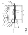
- the width of the aforementioned gap can be changed. This serves to control the amount of coating material which is fed to the surface of a plate. Also, the gap in one embodiment be closed, so as to be able to control the time of delivery. 4. Description of Preferred Embodiments Hereinafter, the invention will be described with reference to FIGS FIG. 1 explained in more detail.
- FIG. 1 shows a device with which a carrier material 6, such as a chip, MDF or HDF plate can be coated in a continuous process.
- the coating materials used are preferably UV- or electron beam-crosslinkable, flowable systems of suitable viscosity.
- a carrier material 6 is supplied and coated with a flowable material 8.
- the coating takes place via a collecting device 5, which adjoins a roller 4.
- a web-shaped material namely a UV-transparent and / or electron-radiation-permeable and radiation-resistant film 3, is guided over the roller 4.
- the film has a smooth, the coating material 8 facing surface when the coating 8 is to have a smooth surface.
- the corresponding surface of the film 3 is structured when the coating 8 according to the invention should have a structured surface.
- the web-shaped material or the film 3 is unrolled from a supply roll or supply roll 1 and finally rolled up again on a roll 2. Between the roller 1 and the roller 4 there are along the transport path for the sheet-like material 3, three further rollers with a relatively small diameter, which serve to guide the sheet-like material.
- the feed throat 13 of small diameter located adjacent to the roll 4, together with the roll 4, causes the sheet material together with the trap 5 to form a cross-sectionally funnel-shaped inlet for coating material 8.
- the coating material 8 for example a lacquer, is suitably brought between the carrier material 6 and the sheet-like material 3 via this funnel shape.
- the funnel-shaped inlet opens into a gap.
- the gap width can be changed to control the supply of coating material.
- roller 4 and the roller 2 there are four further guide rollers with a relatively small diameter, which serve to guide the web-like material from the roller 4 to the roller 2.
- the first guide roller 10 - seen from the roller 4 in the transport direction of the sheet material - causes, together with the roller 4, that the web-like material is guided parallel to the surface of the carrier material 6.
- the film 3 means 7 with which the underlying coating material can be dried and / or cured. These are above all devices for curing with UV light or electron beams.
- a web-shaped smooth or structured material 3 is aligned at the same time from the supply roll 1 both in the longitudinal direction and in the transverse direction and applied synchronously to the carrier material 6 by means of the roller 4 and the catcher 5 on the still liquid coating material.
- the aim of the orientation of the web-shaped material is to synchronize certain points of the carrier material 6 with certain points of the web-like material fitting one above the other.
- the speed of a carrier material or a plate 6 is measured with measuring devices.
- optical measuring devices are used to determine the speed of the carrier material.
- the rotational speed of at least one roller or roller is involved, which is involved in the transport of the sheet-like material.
- the thus obtained information about the transport speed of each plate 6 and transport speed of the sheet material are used for the control.
- the two speeds are thus controlled so that a plate is brought together defined with the web-like material, so as to be able to structure a surface targeted.
- the sheet-like material for example, optical marks, which are detected with optical sensors.
- the transport of the sheet material and / or the transport of the plates 6 are controlled so that a plate is coated in dependence on such an optical marking and the coating is structured in dependence on these optical markings.
- the carrier material with the liquid coating material and the overlying sheet-like material then passes through the curing station 7.
- the liquid coating material 8 is crosslinked and goes into a solid state.
- the surface structure of the web-like material is fixed and imaged in the hardened layer.
- the sheet-like material is removed from the cured solid coating material and wound up again into a roll.
- FIG. 2 shown embodiment provided that a plurality of supply rolls 1 and take-up rolls 2 are present for the web-like material.
- the supply rolls and the Aurwickelrollen can be endlessly connected during production by a device without stop.
- connection is made for reasons of practicality, preferably at speeds up to 120 m / min.
- the respective at rest film receiving station is charged with a roll of web-like material and prepared the automatic connection by a double-sided adhesive tape is glued to the web beginning.
- the beginning of the sheet material is inserted into a gap, which serves to connect. Through this gap at the same time the web-like material is guided, which is currently being unrolled.
- the triggering of the connection is done automatically by electronically detecting the running meters of the roll, from which web-shaped material is unrolled, or sensory Detecting the associated end of a web-shaped material.
- the running web-like material is stored in a dancer device operating as a web store.
- the driven roller is reduced to a speed of about 15 m / min.
- the missing length of the web-like material to the line speed pulls out of the dancer. Accelerate after the connection! the corresponding film roll again up to the maximum speed of, for example, 120 m / min until the dancer roller
- the automatic connection device comprises at least two unwind stations with flap bearings and pneumatic tension shafts.
- the drive of the bends is made by a servo motor, means are available to automatically adjust cars with the films or web-like materials.
- the actual connecting device comprises four pneumatically operated mangle rollers. There are also two cutter blades for cutting the web material after bonding. An automatic braking force regulation of the unwinding rolls is available. This includes dancer rollers, pneumatic proportional linear cylinders with guide and guide rollers and an automatic crack control.
- the carrier material or a plate 6 is first passed through the two superimposed, rotating rollers 4 and 11 passed through and transported. From here, the carrier material 6 reaches a conveyor belt 12, which further transports the carrier material. The web-shaped material or the film 3 and the carrier material 6 are transported at the same speed.
- the distance between the two rollers 4 and 11 can be changed in order to vary the thickness of the coating can.
- the height of the guide roller 10 can be changed in order to influence the thickness of the coating can.
Abstract
Description
Die Erfindung betrifft ein Verfahren für die Beschichtung von Platten, insbesondere von Holzwerkstoffplatten zur Herstellung von Fußbodenpaneelen, mit einem fließfähigen Beschichtungsmaterial.The invention relates to a method for the coating of boards, in particular of wood-based panels for the production of floor panels, with a flowable coating material.
Aus dem Stand der Technik ist eine Reihe von Holzwerkstoffplatten zur Herstellung von Fußbodenpaneelen bekannt. Platten aus Massivholz haben eine ästhetisch besonders ansprechende Oberfläche, sind jedoch sehr teuer. Aus diesem Grund wurden Furnierplatten entwickelt, die eine Grundplatte aus einem relativ kostengünstigen Holzwerkstoff aufweisen, wie zum Beispiel eine kostengünstige Holzart, auf die eine dünne Furnierschicht einer hochwertigeren Holzart aufgebracht Wird. Jedoch sind auch Furnierplatten immer noch relativ teuer, so dass viele Verbraucher Laminatpaneele bevorzugen. Laminatpaneele bestehen im Wesentlichen aus einer ca. 6 bis 8 mm dicken Grundplatte aus MDF- oder HDF-Material auf die eine Dekorpapierschicht aufgeklebt ist. Die Dekorpapierschicht ist mit einem Harz imprägniert und ist in der Regel weiter mit abriebfesten Partikeln versehen. Bei der Erstellung der Laminatpaneele wird durch die Anwendung von Druck und Hitze das Harz ausgehärtet und es entsteht eine extrem abriebfeste und dekorative Oberfläche. In neuester Zeit wurden neue Verfahren entwickelt, um Holzwerkstoffplatten, wie z.B. MDF oder HDF, direkt mit einem Kunststoffmaterial zu bedrucken, d.h. ohne die Verwendung eines Dekorpapiers. Zu diesem Zweck wird die z.B. MDF-Platte abgeschliffen und mit einer Grundierung versehen. Auf diese Grundierung wird in einem zweiten Schritt ein farbliches Dekor aufgedruckt, z.B. ein Holzdekor. Danach werden eine Vielzahl von sehr dünnen Materialschichten aufgebracht, wobei die einzelnen Materialschichten vor dem Auftragen der nächsten Schicht jeweils ausgehärtet werden. Die Materialschichten sind z.B. mehrere, im Wesentlichen durchsichtige Lackschichten aus einem aushärtbaren Kunststoff. Die resultierende Gesamtschicht hat somit einen schichtweisen Aufbau. Zwischen den einzelnen Schichten entstehen Grenzflächen, in denen keine gute Vernetzung stattfindet. Die einzelnen Schichten haben üblicherweise eine Dicke von 10 bis 15 µm und es werden üblicherweise 5 bis 7 Schichten übereinander aufgetragen, so dass sich eine Gesamtstärke des Dünnschichtsystems oder Schichtstapels von ca. 50-105 µm ergibt.From the prior art, a number of wood-based panels for the production of floor panels is known. Solid wood panels have an aesthetically pleasing surface but are very expensive. For this reason, veneer panels have been developed which have a base plate of a relatively inexpensive wood material, such as a low-cost wood species, to which a thin veneer layer of a higher quality wood species is applied. However, veneer sheets are still relatively expensive, so many consumers prefer laminate panels. Laminate panels essentially consist of an approx. 6 to 8 mm thick base plate made of MDF or HDF material, to which a decor paper layer is glued. The decor paper layer is impregnated with a resin and is usually further provided with abrasion-resistant particles. When creating the laminate panels, the application of pressure and heat hardens the resin and creates an extremely abrasion-resistant and decorative surface. Recently, new methods have been developed to print wood-based panels, such as MDF or HDF, directly with a plastic material, ie without the use of decorative paper. For this purpose, the MDF board, for example, is sanded off and primed. In a second step, a colored decor is printed on this primer, for example a wood decor. Thereafter, a plurality of very thin material layers are applied, wherein the individual material layers each cured before applying the next layer. The material layers are, for example, a plurality of, essentially transparent lacquer layers of a hardenable plastic. The resulting overall layer thus has a layered structure. Between the individual layers arise interfaces in which no good networking takes place. The individual layers usually have a thickness of 10 to 15 .mu.m and usually 5 to 7 layers are applied one above the other, resulting in a total thickness of the thin-layer system or layer stack of about 50-105 .mu.m.
Wie der Name Holzwerkstoffplatte bereits beinhaltet, fallen hierunter alle Holzwerkstoffe im weitesten Sinne, also Platten, die aus Holz bestehen, bzw. die unter Verwendung von Holzmaterialien hergestellt sind. Hierzu gehören beispielsweise aber nicht abschließend Platten aus OSB, MDF oder HDF, Spanplatten, Voll- und Massivholz, Furnier- und Fertigparkett und andere. Insbesondere betrifft diese Erfindung verbesserte Holzwerkstoffplatten zur Verwendung als Fußbodenbelag oder Wand- bzw. Deckenbelag.As the name already refers to wood-based panel, this includes all wood-based materials in the broadest sense, ie panels that are made of wood, or that are made using wood materials. These include, but are not limited to, OSB panels, MDF or HDF, chipboard, solid and solid wood, veneered and prefinished parquet and others. In particular, this invention relates to improved wood-based panels for use as a floor covering or wall or ceiling covering.
Aus der Druckschrift
Aus der
Aus der Druckschrift
Aus der
Es ist die Aufgabe der Erfindung, ein neues Verfahren zu schaffen, mit dem eine schnelle und kostengünstige strukturierte Beschichtung von Platten, insbesondere für die Herstellung von Fußbodenpaneelen, in guter Qualität möglich ist.It is the object of the invention to provide a new method with which a fast and cost-effective structured coating of plates, in particular for the production of floor panels, in good quality is possible.
Diese und andere Ziele, welche aus der folgenden Beschreibung hervorgehen, werden durch die vorliegende Erfindung gelöst.These and other objects, which will become apparent from the following description, are achieved by the present invention.
Die obige Aufgabe wird durch ein Verfahren nach Anspruch 1 sowie ein alternatives Verfahren nach Anspruch 2 gelöst.The above object is achieved by a method according to claim 1 and an alternative method according to
Zur Lösung der Aufgabe kann eine Vorrichtung verwendet werden, die Transportmittel für den Transport von Platten umfasst. Die Vorrichtung umfasst zudem eine Zuführungseinrichtung, mit der Beschichtungsmaterial auf die Plattenoberfläche gebracht werden kann. Im Anschluss an die Zuführungseinrichtung sind oberhalb der Platte Mittel für das Trocknen und / oder Harten des Beschichtungsmaterials vorgesehen. Im Unterschied zum eingangs genannten Stand der Technik
Wird eine Materialbahn mit strukturierter Oberfläche eingesetzt, so kann die Oberfläche des Beschichtungsmaterials erfindungsgemäß mit einer Struktur versehen werden, ohne großen Druck ausüben zu müssen. Da das Beschichtungsmaterial in diesem Zustand getrocknet und/ oder gehärtet wird, gelingt so das Beschichten einer Platte mit strukturierter Oberfläche, ohne hierfür wie beim aus der Druckschrift
Wird eine Materialbahn mit glatter Oberfläche eingesetzt, so ist so ein Trocknen und / oder Härten unter Luftabschluss möglich. Ein Trocknen und / oder Härten unter Luftabschluss ist vielfach gewünscht, so zum Beispiel um im Fall einer Härtung eines Lacks mit UV-Licht eine besonders große Vernetzung, also einen besonders großen Umsatz an Doppelbindungen innerhalb des Lacks zu erzielen. Im Fall einer Härtung mit Elektronenstrahlen ist ein Luftabschluss in der Regel erforderlich.If a material web with a smooth surface is used, so drying and / or curing under exclusion of air is possible. Drying and / or curing under exclusion of air is frequently desired, for example in order to achieve particularly high crosslinking in the case of curing of a varnish with UV light, ie a particularly high conversion of double bonds within the varnish. In the case of curing with electron beams, an air seal is usually required.
Die Erfindung betrifft ein neues Verfahren zur Beschichtung einer Holzwerkstoffplatte, insbesondere einer Span-, MDF- oder HDF-Platte, mit einem fließfähigen Kunststoffmaterial. Insbesondere betrifft das Verfahren die Herstellung von Paneelen, wie z.B. die Herstellung von Fußbodenpaneelen. Bei diesem Verfahren wird in einem einzigen Arbeitsschritt eine dicke Schicht von erfindungsgemäß mind. 30 µm aus einem Kunststoffmaterial auf die Holzwerkstoffplatte aufgetragen. Das Kunststoffmaterial ist zumindest nach dem Austrocknen oder Härten vorzugweise durchsichtig. Die Schicht wird vorzugsweise in einem einzigen Arbeitsgang in einer Dicke von 30 bis 150 µm aufgetragen, besonders bevorzugt in einer Dicke von 80 bis 110 µm und insbesondere bevorzugt in einer Dicke von etwa 95 µm aufgetragen. In einem weiteren Schritt wird die Schicht aus Kunststoffmaterial ausgehärtet. Die Verwendung einer einzelnen dicken Schicht anstelle einer Folge von vielen dünnen Schichten hat eine Reihe von Vorteilen. Zum einen können größere abriebfeste Partikel, wie z.B. größere Korundpartikel, vorgesehen werden, als es bei einem Dünnschichtsystem möglich ist. Bei den Dünnschichtsystemen, in denen die einzelnen dünnen Schichten nur eine Dicke von 10 bis 15 µm haben, und die jeweils für sich nacheinander ausgehärtet werden, können nämlich nur relativ kleine Partikel verwendet werden, da die Partikel vorzugsweise so weit wie möglich in den Schichten eingebunden sein sollten.The invention relates to a novel process for coating a wood-based panel, in particular a particleboard, MDF or HDF board, with a flowable plastic material. In particular, the method relates to the production of panels, such as the manufacture of floor panels. In this method, a thick layer of at least 30 .mu.m of a plastic material is applied to the wood-based panel in a single step. The plastic material is preferably transparent at least after drying or curing. The layer is preferably applied in a single operation in a thickness of 30 to 150 microns, more preferably in a thickness of 80 to 110 microns and most preferably in a thickness applied by about 95 microns. In a further step, the layer of plastic material is cured. The use of a single thick layer instead of a series of many thin layers has a number of advantages. On the one hand, larger abrasion-resistant particles, such as, for example, larger corundum particles, can be provided than is possible with a thin-layer system. In the thin-film systems in which the individual thin layers only have a thickness of 10 to 15 .mu.m, and which are cured one after the other, in fact only relatively small particles can be used, since the particles are preferably incorporated as far as possible in the layers should be.
Das fließfähige Kunststoffmaterial ist vorzugsweise ein Acrylatsystem. Unter einem Acrylatsystem wird hierin beispielsweise ein polymerisationsfähiges Gemisch von doppelbindungshaltigen mono-, di- und mehrfachfunktionellen acrylsäurebasierenden Verbindungen verstanden. Typische Vertreter sind beispielsweise Dipropylenglycoldiacrylat, 1,6-Hexandioldiacrylat, Polyurethan-Acrylsäureester, Polyester-Acrylsäurester wie sie im Produktionsprogramm der Firma BASF unter dem Handelsnamen Laromer™- Typen am Markt erhältlich sind.The flowable plastic material is preferably an acrylate system. By an acrylate system is meant, for example, a polymerizable mixture of double bond-containing mono-, di- and polyfunctional acrylic acid-based compounds. Typical representatives are for example Dipropylenglycoldiacrylat, 1,6-Hexandioldiacrylat, polyurethane acrylic acid ester, polyester acrylic acid ester as they are available in the production program of the company BASF under the trade name Laromer ™ types on the market.
Die Holzwerkstoffplatte wird vor der Beschichtung mit dem fließfähigen Kunststoffmaterial vorzugweise mit einem farbigen Dekordruck versehen, wie z.B. mit einem Holzdekor. Das Kunststoffmaterial wird über den Dekordruck aufgetragen und ist vorzugsweise möglichst durchsichtig. Das Verfahren kann dabei beispielsweise wie folgt ablaufen:The wood-based panel is preferably provided with a colored decorative print prior to coating with the flowable plastic material, e.g. with a wood decor. The plastic material is applied via the decor pressure and is preferably as transparent as possible. The process can be carried out, for example, as follows:
Zuerst wird die Trägerplatte, wie z.B. eine MDF-Platte, feingeschliffen und ausgerichtet bzw. kalibriert. Danach wird ein Primer aufgebracht und vorzugweise eine Grundierung aufgetragen. Anschließend erfolgt der Druck des Dekors auf den Primer bzw. die Grundierung. In einem weiteren Schritt wird ein weiterer Primer aufgetragen, der vorzugweise ein geeigneter Primer für die folgende Schicht aus Kunststoffmaterial ist. Dieser Primer wird vorzugsweise in einer Menge von bis zu 10 g/m2, besonders bevorzugt von etwa 5 g/m2 aufgetragen. Auf den Primer wird dann beispielsweise eine einzelne dicke Schicht eines Acrylatsystems durch z.B. Walzenauftrag aufgebracht. Dies geschieht vorzugsweise in einer Menge von bis zu 100 g/m2, besonders bevorzugt von etwa 65 g/m2. Auf das noch nicht gehärtete Acrylatsystem werden dann vorzugsweise Korundpartikel gestreut und zwar je nach geforderter Abriebklasse bis zu 70 g/m2, bevorzugt 45 g/m2. Über diese Schicht erfolgt dann vorzugweise ein Toplackauftrag über eine Strukturgeberfolie mit bevorzugt 2 - 100 g/m2, besonders bevorzugt 30 g/m2. Zum Schluss werden dann alle Schichten in einem einzigen Arbeitsgang mittels UV - Strahlung durchgehärtet. Das gehärtete Acrylatsystem ist vorzugweise möglichst durchsichtig, damit der darunterliegende Dekordruck sichtbar ist.First, the carrier plate, such as an MDF plate, is honed and aligned or calibrated. Thereafter, a primer is applied and preferably applied a primer. Subsequently, the decoration is printed on the primer or the primer. In a further step, a further primer is applied, which is preferably a suitable primer for the following layer of plastic material. This primer is preferably applied in an amount of up to 10 g / m 2 , more preferably of about 5 g / m 2 . For example, a single thick layer of an acrylate system is applied to the primer by, for example, roller application. This is preferably done in an amount of up to 100 g / m 2 , more preferably of about 65 g / m 2 . On the not yet hardened Acrylate system are then preferably scattered corundum particles and depending on the required abrasion class up to 70 g / m 2 , preferably 45 g / m 2 . Over this layer is then preferably a Toplackauftrag a patterning film with preferably 2 - 100 g / m 2 , more preferably 30 g / m 2 . Finally, all layers are cured by UV radiation in a single operation. The cured acrylate system is preferably as transparent as possible, so that the underlying decorative pressure is visible.
Die Aushärtung des Kunststoffmaterials erfolgt vorteilsweise über eine Polymerisation des Kunststoffmaterials und nicht über eine Polykondensation. Das Kunststoffmaterial ist dementsprechend vorzugsweise ein polymerisationsfähiges Acrylatsystem. Besonders bevorzugt ist das Kunststoffmaterial, wie beispielsweise das polymerisationsfähige Acrylatsystem, ein mit UV-Strahlen aushärtbarer Kunststoff. Dabei dient die UV-Strahlung dazu, die Polymerisation zu starten. Da die Polymerisation jederzeit gestoppt werden kann ist es somit möglich in der einzelnen dicken Schicht, die z.B. 95 µm betragen kann, einen Vernetzungsgradienten und damit einen Härtungsgradienten herzustellen. Der Härtungsgradient wird über eine einmalige, über die gesamte Schichtstärke stattfindende Polymerisation mit möglichst vollständigem Umsatz erzeugt. Dies steht im Gegensatz zum Lackieren mit vielen Dünnschichten, wobei diese Schicht für Schicht aufgetragen und dann mittels Strahlung "angeliert" werden, d.h. es wird vorzeitig die Reaktion abgebrochen. Damit hat man über den gesamten Querschnitt aller Schichten keine durchgehende Polymerbildung sondern Grenzschichten.The curing of the plastic material is advantageously carried out via a polymerization of the plastic material and not via a polycondensation. Accordingly, the plastic material is preferably a polymerizable acrylate system. Particularly preferred is the plastic material, such as the polymerizable acrylate system, a UV-curable plastic. The UV radiation serves to start the polymerization. Since the polymerization can be stopped at any time, it is thus possible in the single thick layer, e.g. May be 95 microns, a Vernetzungsgradienten and thus produce a cure gradients. The curing gradient is generated over a single, over the entire layer thickness occurring polymerization with the highest possible conversion. This is in contrast to painting with many thin films, which are applied layer by layer and then "gelled" by radiation, i. it is prematurely aborted the reaction. Thus, over the entire cross-section of all layers, there is no continuous polymer formation but boundary layers.
In einer vorteilhaften Weiterbildung des Verfahrens werden nass in nass mehrere Schichten aufgetragen (wie z.B. Primer, Acrylat (Walzenauftrag), Korund; Toplackauftrag) und in einem einzigen Schritt vorzugsweise durch UV - Anregung polymerisiert. Die Acrylatschicht wird dabei erfindungsgemäß in einer einzelnen dicken Schicht gehärtet. Die einzelnen Schichten unterscheiden sich in ihrer Funktion und damit auch im chemischen Aufbau: Der Primer hat die Aufgabe, eine gute Haftung zwischen Druck- und Kunststoffschicht herzustellen. Die mittlere Schicht ist flexibel eingestellt um innere Spannungen abzubauen und eine Versprödung zu vermeiden sowie Stoßenergie beim Begehen abzufangen, wenn die beschichtete Platte z.B. als Fußbodenpaneel verwendet wird. Die Toplackschicht hingegen ist so modifiziert, dass sie zu hoher Härte und Kratzfestigkeit führt. Da es beim Nass- in Nassauftrag zu Durchmischungen der Schichten kommt, gibt es keine Grenzschichten sondern tatsächlich einen Härtegradienten von oben nach unten. Chemisch zusammengefasst: Die Polymerisation wird so durchgeführt, dass ein nahezu vollständiger Doppelbindungsumsatz über die gesamte Schicht erreicht wird. Der Primer ist vorzugsweise so ausgelegt, dass durch stärkere Funktionalisierung der Acrylatmischung ein besseres Haften erreicht wird. Die mittlere Schicht weist insbesondere Kettenwachstum und nur geringfügigere Vernetzung auf. Die Toplackschicht enthält vorzugsweise ein hochvernetzungsfähiges Acrylatsystem.In an advantageous development of the process, several layers are applied wet-on-wet (for example primer, acrylate (roll application), corundum, topcoat application) and polymerized in a single step, preferably by UV excitation. The acrylate layer is cured according to the invention in a single thick layer. The individual layers differ in their function and thus also in the chemical structure: The primer has the task of producing good adhesion between the printing and the plastic layer. The middle layer is flexibly adjusted to reduce internal stresses and to avoid embrittlement and to absorb impact energy when walking when the coated board is used as a floor panel, for example. The Toplackschicht however, it is modified to lead to high hardness and scratch resistance. Since the wet-to-wet application causes intermixing of the layers, there are no boundary layers but actually a hardness gradient from top to bottom. Chemically summarized: The polymerization is carried out so that a nearly complete double bond conversion over the entire layer is achieved. The primer is preferably designed so that better adhesion is achieved by greater functionalization of the acrylate mixture. In particular, the middle layer has chain growth and only minor cross-linking. The Toplackschicht preferably contains a highly crosslinkable acrylate system.
Um die Abriebfestigkeit der Schicht zu erhöhen werden vorzugsweise abriebfeste Partikel, insbesondere Korundpartikel, in die Schicht eingebracht. Da die Schicht sehr dick ist, ist es möglich relativ dicke Partikel einzubringen, die bessere Abriebeigenschaften mit sich bringen, als kleinere Partikel. Abhängig von der verwendeten Schichtdicke werden somit z.B. Korundpartikel in einem Bereich von DF 220 bis DF 280 nach FEPA-Spezifikation (Federation of European Producers of Abrasives) eingesetzt. Diese haben dann eine Durchschnittskorngröße D50 von 36,5 bis 63,0 µm. Besonders bevorzugt werden Partikel im Bereich von DF 240 bis DF 280 verwendet, d.h. mit Korngrößen D50 von 44,5 bis 36,5 µm. Bei den Eingangs erwähnten Schichtsystemen mit mehreren dünnen Einzelschichten (sogenannte Dünnschichtsysteme), die übereinander aufgetragen werden, müssen relativ kleine Partikel (wie z.B. Korund-Partikel) verwendet werden, da diese ansonsten zu weit aus den einzelnen Schichten hervorstehen würden. Die Partikelgröße liegt dabei üblicherweise im Bereich von DF 320 bis DF 500 nach FEPA-Spezifikation. Das heißt, die bisher verwendbaren Korngrößen der abriebfesten Partikel waren auf eine Durchschnittskorngröße D50 von 29,2 bis 12,8 µm beschränkt. Diese relativ kleinen Partikel führen bei gleicher Zusatzmenge zu niedrigeren Abriebwerten, d.h. bei gleicher Abriebklasse muss bei feineren Partikeln eine größere Gewichtsmenge verwendet werden, als bei größeren Partikeln. Außerdem führen feinere Partikel zu einer schlechteren Transparenz der Oberfläche und zu Vergrauungserscheinungen.In order to increase the abrasion resistance of the layer, abrasion-resistant particles, in particular corundum particles, are preferably introduced into the layer. Since the layer is very thick, it is possible to incorporate relatively thick particles which have better abrasion properties than smaller particles. Depending on the layer thickness used, eg corundum particles in a range from DF 220 to DF 280 according to the FEPA specification (Federation of European Producers of Abrasives) are used. These then have an average grain size D 50 of 36.5 to 63.0 microns. Particular preference is given to using particles in the range from DF 240 to DF 280, ie having particle sizes D 50 of 44.5 to 36.5 μm. In the case of the above-mentioned layer systems with several thin individual layers (so-called thin-layer systems), which are applied to one another, relatively small particles (such as corundum particles) must be used, since otherwise they would protrude too far from the individual layers. The particle size is usually in the range of DF 320 to DF 500 according to the FEPA specification. That is, the previously usable grain sizes of the abrasion-resistant particles were limited to an average grain size D 50 of 29.2 to 12.8 microns. These relatively small particles lead to lower abrasion values with the same additional amount, ie with the same abrasion class, a larger amount by weight must be used with finer particles than with larger particles. In addition, finer particles lead to a poorer transparency of the surface and graying phenomena.
Das Einbringen der Partikel in die Schicht kann nach Auftragen der Schicht erfolgen, in dem die Partikel zum Beispiel auf die noch nicht ausgehärtete Schicht aufgestreut werden. Nachdem die Partikel in die Schicht eingesunken sind oder eingepresst wurden, wird das Material ausgehärtet, so dass die Partikel fest in der Schicht eingeschlossen werden. Eine andere Möglichkeit besteht darin, die Partikel vor dem Auftragen der Schicht in das fließfähige Kunststoffmaterial einzubringen, zum Beispiel in Form einer Dispersion.The introduction of the particles into the layer can be carried out after application of the layer in which the particles are sprinkled, for example, on the not yet cured layer. After the particles have sunk or pressed into the layer, the material is cured so that the particles are firmly entrapped in the layer. Another possibility is to introduce the particles before the application of the layer in the flowable plastic material, for example in the form of a dispersion.
Gemäß der ersten Alternative der Erfindung wird vor dem Aushärtungsschritt, also nach dem die Schicht auf die Platte aufgetragen wurde, eine Materialbahn mit strukturierter Oberfläche, praktisch ohne Druck auszuüben, auf die Schicht aus Kunststoffmaterial aufgebracht. Auf diese Weise wird eine Struktur in die Schicht aus Kunststoffmaterial eingeprägt. Da die Schicht zu diesem Zeitpunkt noch flüssig ist, muss praktisch kein Druck aufgewendet werden. In einem nächsten Schritt wird die Schicht aus Kunststoffmaterial getrocknet und / oder gehärtet, wodurch die in die Schicht aus Kunststoffmaterial eingebrachte Struktur fixiert Wird. Danach kann in einem weiteren Schritt die Materialbahn mit strukturierter Oberfläche wieder entfernt werden. In der zweiten Alternative der Erfindung wird eine Strukturwalze verwendet, um eine Struktur in die Schicht aus Kunststoffmaterial einzuprägen. Dies geschieht wiederum nach dem Auftragen des Kunststoffmaterials auf die Platte aber vor dem Aushärten des Kunststoffmaterials. Möglichst direkt nach dem Aufprägen der Struktur wird in einem nächsten Schritt die Schicht aus Kunststoffmaterial getrocknet und /oder gehärtet, wodurch die in die Schicht aus Kunststoffmaterial eingebrachte Struktur fixiert wird. Aufgrund der erfindungsgemäß großen Dicke der Schicht sind Strukturtiefen von o bis zu 80 µm möglich. Besonders bevorzugt sind Strukturtiefen von 20 bis zu 80 µm und besonders bevorzugt von bis zu ca. 35 µm. Im Stand der Technik, bei dem ein Schichtsystem von einzelnen Dünnschichten verwendet wurde, war es bisher nicht möglich Strukturtiefen von mehr als 5 bis 10 µm zu erzeugen. Diese geringen Strukturtiefen sind für viele Zwecke nicht ausreichend. Um z.B. eine realistische Echtholz-Nachahmung zu realisieren, müssen tiefere Strukturen in die Schicht eingeprägt werden. Mit den sehr tiefen Strukturen gemäß dem vorliegenden Verfahren können daher Muster und Strukturen in die Schicht eingebracht werden, die ästhetisch besonders ansprechend sind und bisher nicht möglich waren. Eine Strukturtiefe von 35 µm ist deutlich fühlbar und mit dem bloßen Auge sichtbar und eignet sich besonders, um die Struktur von Echtholzböden nachzuahmen.According to the first alternative of the invention, prior to the curing step, ie after the layer has been applied to the plate, a material web having a structured surface, practically without pressure, is applied to the layer of plastic material. In this way, a structure is embossed in the layer of plastic material. Since the layer is still liquid at this time, virtually no pressure needs to be expended. In a next step, the layer of plastic material is dried and / or cured, whereby the introduced into the layer of plastic material structure is fixed. Thereafter, in a further step, the material web with structured surface can be removed again. In the second alternative of the invention, a pattern roll is used to emboss a structure in the layer of plastic material. This in turn happens after the application of the plastic material to the plate but before the curing of the plastic material. If possible directly after the structure has been impressed, in a next step the layer of plastic material is dried and / or hardened, whereby the structure introduced into the layer of plastic material is fixed. Due to the thickness of the layer according to the invention, structure depths of 0 to 80 μm are possible. Structural depths of from 20 to 80 μm and particularly preferably up to about 35 μm are particularly preferred. In the prior art, in which a layer system of individual thin films was used, it was not possible to produce structure depths of more than 5 to 10 microns. These small structure depths are not sufficient for many purposes. For example, to realize a realistic real wood imitation, deeper structures must be imprinted into the layer. With the very deep structures according to the present method, therefore, patterns and structures can be incorporated into the layer that are aesthetically pleasing and not previously possible were. A texture depth of 35 microns is clearly felt and visible to the naked eye and is particularly suitable to imitate the structure of real wood floors.
In einer alternativen, nicht erfindungsgemäßen Ausführungsform wird eine Materialbahn mit glatter Oberfläche ohne größeren Druck auszuüben auf die Schicht auf Kunststoffmaterial gelegt. Auf diese Weise wird verhindert, dass Luft an das Kunststoffmaterial gelangt. In einem nächsten Schritt wird die Schicht aus Kunststoffmaterial unter Luftabschluss getrocknet und / oder gehärtet. In einem weiteren Schritt wird die Materialbahn mit glatter Oberfläche wieder entfernt.In an alternative embodiment, not according to the invention, a material web with a smooth surface is applied to the layer of plastic material without exerting much pressure. In this way it is prevented that air gets to the plastic material. In a next step, the layer of plastic material is dried and / or cured in the absence of air. In a further step, the material web with a smooth surface is removed again.
Die verwendeten Materialbahnen, ob mit glatter oder strukturierter Oberfläche, sind vorzugsweise für UV-Licht durchlässig. Wenn ein UV aushärtbarer Kunststoff verwendet wird, ist es somit möglich den Kunststoff auszuhärten, obwohl dieser von der Materialbahn abgedeckt ist.The material webs used, whether with a smooth or structured surface, are preferably permeable to UV light. If a UV-curable plastic is used, it is thus possible to cure the plastic, although it is covered by the material web.
Das vorgestellte Verfahren bietet besondere Vorteile bei der Beschichtung von Holzwerkstoffplatten aus Echtholz, wie Furnier oder Parkett, beispielsweise Fertigparkett. Bisher war es ein Nachteil derartiger Echtholzplatten, dass die Oberflächen relativ empfindlich sind. Mit dem erfindungsgemäßen Verfahren können nun auch Echtholzböden mit einer Beschichtung versehen werden, die hohe Abriebwerte hat und die dennoch aufgrund der eingearbeiteten dreidimensionalen Struktur eine ästhetisch ansprechende Oberfläche aufweist. Wollte man bisher Echtholzböden mit einer abriebfesten Beschichtung versehen, um die Haltbarkeit von zum Beispiel Fußböden aus diesem Material zu erhöhen, hat sich die natürliche dreidimensionale Struktur des Echtholzes als nachteilig erwiesen. Die im feuchten Zustand aufgetragene Lackierung oder Beschichtung tendiert nämlich dazu, in die Vertiefungen der natürlichen Struktur zu fließen, so dass die Beschichtung der vorstehenden Bereiche zwischen den Vertiefungen nur unzureichend ist. Trägt man jedoch eine dickere Schicht auf, um auch die vorstehenden Bereiche zwischen den Vertiefungen mittels der Beschichtung zu schützen, wird die natürliche dreidimensionale Struktur des Echtholzes vollständig aufgefüllt, so dass eine unerwünscht ebene Oberfläche resultiert. Eine derartige ebene Oberfläche beeinträchtigt nämlich die optische Wirkung, die durch die dreidimensionalen Strukturen erreicht werden soll; das heißt den Eindruck eines echten Holzmaterials zu erzeugen, bzw. hervorzuheben. Das Problem der Auffüllung der natürlichen Struktur des Echtholzes tritt jedoch auch schon bei sehr geringen Dicken der Beschichtung auf. Im Stand der Technik wurde versucht, dieses Problem dadurch zu vermeiden, dass maschinell tiefere Strukturen in die Echtholzoberfläche eingefräst wurden. Dieser zusätzliche Verfahrensschritt verteuert jedoch die Produkte und macht zudem die Lackierung aufgrund des oben beschriebenen Problems, dass das flüssige Beschichtungsmaterial sich in den Vertiefungen sammelt, noch schwieriger. Obwohl diese Probleme schon seit langem bekannt sind, ist es bisher nicht gelungen diese zufriedenstellend zu lösen. Mit der vorliegenden Erfindung bietet sich nunmehr erstmals die Gelegenheit auch Echtholzplatten mit einer abriebfesten Beschichtung zu versehen, die trotzdem aufgrund einer geeignet eingeprägten dreidimensionalen Struktur in überzeugender Weise die gewünschten ästhetischen Eigenschaften der Echtholzplatten konserviert. Insbesondere ist es mit der vorliegenden Erfindung erstmals möglich, Echtholzböden aus Voll- und Massivholz, wie z.B. Holzdielen, oder aus Holzfurnier und Fertigparkett mit sehr hohen Abriebwerten herzustellen, die trotzdem eine dreidimensionale Oberflächenstruktur aufweisen, die den Eindruck eines Echtholzmaterials erweckt.The presented method offers particular advantages in the coating of wood-based panels made of real wood, such as veneer or parquet, for example, engineered parquet. So far, it has been a disadvantage of such real wood panels that the surfaces are relatively sensitive. With the method according to the invention, real wood floors can now also be provided with a coating which has high abrasion values and which nevertheless has an aesthetically pleasing surface due to the incorporated three-dimensional structure. If real wood floors were previously provided with an abrasion-resistant coating in order to increase the durability of, for example, floors made of this material, the natural three-dimensional structure of the real wood has proven to be disadvantageous. Namely, the paint or coating applied in the wet state tends to flow into the recesses of the natural structure, so that the coating of the protruding portions between the recesses is insufficient. However, by applying a thicker layer to protect the protruding areas between the recesses by means of the coating, the natural three-dimensional structure of the real wood is completely filled up, resulting in an undesirably flat surface. Namely, such a flat surface impairs the optical effect caused by the three-dimensional Structures to be achieved; that is, to create or emphasize the impression of a real wood material. However, the problem of filling the natural structure of the real wood occurs even at very low thicknesses of the coating. The prior art has attempted to avoid this problem by machine-milling deeper structures into the real wood surface. However, this additional process step makes the products more expensive and, moreover, makes the coating even more difficult due to the above-described problem that the liquid coating material collects in the depressions. Although these problems have been known for a long time, it has not yet been possible to solve them satisfactorily. With the present invention, now for the first time offers the opportunity to provide real wood panels with an abrasion-resistant coating, which still preserves convincingly the desired aesthetic properties of real wood panels due to a suitably embossed three-dimensional structure. In particular, it is possible for the first time with the present invention to produce real wood floors made of solid and solid wood, such as wood planks, or wood veneer and engineered parquet with very high abrasion values, which nevertheless have a three-dimensional surface structure, which gives the impression of a real wood material.
In einer Ausführungsform umfasst die Zuführungseinrichtung eine Auffangeinrichtung für das Beschichtungsmaterial, die angrenzend an die Transportmittel für den Transport der Platten angeordnet ist. Die Auffangeinrichtung grenzt des Weiteren an eine Walze für den Transport der Materialbahn an. Die Auffangeinrichtung ist so beschaffen, dass flüssiges, in der Auffangeinrichtung befindliches Beschichtungsmaterial zur Walze fließt. Es wird so erreicht, dass bei hinreichend großer Befüllung der Auffangeinrichtung flüssiges Beschichtungsmaterial vollständig eine Materialbahn mit einem Flüssigkeitsfilm zu überziehen vermag, wenn eine Materialbahn über die Walze transportiert wird. Insgesamt kann so bei hinreichender Zufuhr von flüssigem Beschichtungsmaterial erreicht werden, dass das flüssige Beschichtungsmaterial vollständig den Raum zwischen der Oberfläche einer Platte und der darüber befindlichen Materialbahn ausfüllt. Es gelangt dann besonders zuverlässig keine Luft in den Bereich. Eine Härtung kann so besonders zuverlässig unter Luftabschluss durchgeführt werden.In one embodiment, the supply device comprises a coating material catcher disposed adjacent to the transport means for transporting the plates. The collecting device further adjoins a roller for transporting the material web. The collecting device is designed so that liquid, located in the catcher coating material flows to the roller. It is thus achieved that, given a sufficiently large filling of the collecting device, liquid coating material can completely coat a material web with a liquid film when a material web is transported over the roller. Overall, it can be achieved with sufficient supply of liquid coating material that the liquid coating material completely fills the space between the surface of a plate and the material web located above it. It then gets very reliable no air in the area. Curing can be carried out so particularly reliably under exclusion of air.
Auch ist es bei dieser Ausführungsform möglich, relativ dicke Lackschichten mit einer Gesamtdicke von beispielsweise 80 bis 100 µm Dicke aufzutragen und einheitlich zu trocknen sowie zu härten. Dies wiederum ermöglicht es, relativ dicke abriebfeste Partikel wie Korund mit einem Durchmesser von bis zu 100 µm innerhalb des Lacks einzubetten. Da mit dem Durchmesser der abriebfesten Partikel die Abriebfestigkeit zunimmt, kann so eine relativ hohe Abriebfestigkeit erreicht werden. Mit zunehmendem Durchmesser der abriebfesten Partikel kann zugleich dennoch auch die Menge an Abriebmaterial gesenkt werden. Es gelingt so sowohl eine Verbesserung von Abriebwerten als auch eine Verbesserung der Transparenz der abriebfesten Beschichtung.Also, in this embodiment, it is possible to apply relatively thick paint layers having a total thickness of, for example, 80 to 100 μm in thickness and to uniformly dry and cure. This in turn makes it possible to embed relatively thick abrasion-resistant particles such as corundum with a diameter of up to 100 μm within the paint. Since the abrasion resistance increases with the diameter of the abrasion-resistant particles, a relatively high abrasion resistance can be achieved. Nevertheless, as the diameter of the abrasion-resistant particles increases, the amount of abrasive material can also be reduced. This achieves both an improvement in abrasion values and an improvement in the transparency of the abrasion-resistant coating.
Besonders bevorzugt sind Partikelkorngrößen von DF 220 bis DF 280 FEPA. Die Dicke der Schicht beträgt vorzugsweise 30 bis 150 µm, besonders bevorzugt 80 bis 110 µm.Particle grain sizes of DF 220 to DF 280 FEPA are particularly preferred. The thickness of the layer is preferably 30 to 150 μm, more preferably 80 to 110 μm.
In einer Ausführungsform der Erfindung umfassen die Mittel für den Transport von Platten ein umlaufendes Transportband, auf das die Platten für den Transport abgelegt werden.In one embodiment of the invention, the means for transporting plates comprise a circulating conveyor belt onto which the plates are deposited for transport.
In einer bevorzugten Weiterbildung des Verfahrens werden nach dem Auftragen der Schicht aus Kunststoffmaterial, aber vor dem Aushärten oder Trocknen derselben, Fremdmaterialien in die Schicht eingebracht, zum Beispiel eingestreut, um beispielsweise einen ästhetisch ansprechenden Effekt zu erzielen. Die Fremdmaterialien sind bevorzugt Naturstoffe wie Kork oder Hanf, aber auch Kunststoffe und Metallpartikel sind geeignet. Die Fremdmaterialien können so eingebracht werden, dass sie zum Teil reliefartig aus der Schicht hervorstehen oder aber so, dass sie vollständig in der Schicht eingesunken sind. Die Schicht ist dabei vorzugsweise durchsichtig, so dass die darin befindlichen Fremdkörper sichtbar sind. Zum Beispiel können in die flüssige Materialschicht Blätter oder Baumnadeln eingelegt werden, die vorzugsweise vollständig in der Schicht eingesunken und von dieser umgeben sind. Anschließend wird die durchsichtige Schicht ausgehärtet. Da die z.B. Naturmaterialien völlig von der Schicht, die zum Beispiel ein Acrylharz sein kann, umgeben sind und damit vor Luft und Witterungseinflüssen geschützt sind, findet kein Zerfall der Naturstoffe statt. Eine derartig behandelte Platte, mit einer durchsichtigen harten Kunststoffschicht, in der Fremdmaterialien eingebracht sind, kann somit einen ästhetisch äußerst ansprechenden Effekt haben. Weitere denkbare Materialien sind zum Beispiel Laub, Zweige, Äste oder Wolle. Das Einbringen von Fremdmaterialien wird durch die relativ große Dicke der Schicht ermöglicht.In a preferred embodiment of the method, after the application of the layer of plastic material, but before the curing or drying of the same, foreign materials are introduced into the layer, for example, interspersed, for example, to achieve an aesthetically pleasing effect. The foreign materials are preferably natural materials such as cork or hemp, but also plastics and metal particles are suitable. The foreign materials can be introduced in such a way that they partially protrude from the layer in relief, or else that they have completely sunk into the layer. The layer is preferably transparent, so that the foreign bodies therein are visible. For example, leaves or tree needles can be inserted into the liquid material layer, which are preferably completely sunk in and surrounded by the layer. Subsequently, the transparent layer is cured. Since, for example, natural materials are completely surrounded by the layer, which can be an acrylic resin, for example, and thus are protected from air and weathering are protected, there is no decomposition of natural products. Such a treated plate, with a transparent hard plastic layer in which foreign materials are introduced, can thus have an aesthetically very appealing effect. Other conceivable materials are, for example, leaves, twigs, branches or wool. The introduction of foreign materials is made possible by the relatively large thickness of the layer.
In einer Ausführungsform der Erfindung wird die Materialbahn von einer Walze abgerollt, über weitere Walzen parallel zur Oberfläche von Platten geführt, die transportiert werden, und dann wieder von einer Walze aufgerollt. Im Unterschied zum eingangs genannten Stand der Technik genügt ein Austausch der Materialbahn, wenn eine Oberflächenstruktur verändert werden soll oder aber wenn eine Struktur auf der Materialbahn Beschädigungen beispielsweise aufgrund von Verschleißerscheinungen aufweist. Durch den Einsatz einer Materialbahn kann außerdem eine gleichbleibende Qualität einer erzeugten Oberflächenstruktur sichergestellt werden, da im Unterschied zu einer Walze mit strukturierter Oberfläche mit dem Abrollen der Materialbahn die Qualität der Oberfläche der Materialbahn nicht verändert wird, die die Struktur erzeugt. Hinzu kommt, dass die Struktur in der Oberfläche der Beschichtung praktisch drucklos erzeugt wird, so dass die Oberfläche der Materialbahn auch aus diesem Grund praktisch keiner Verschleißerscheinung unterliegt.In one embodiment of the invention, the web of material is unrolled from a roll, guided over further rolls parallel to the surface of sheets which are being transported, and then rolled up again by a roll. In contrast to the aforementioned prior art, an exchange of the material web is sufficient if a surface structure is to be changed or if a structure on the material web has damage, for example due to signs of wear. By using a material web, a consistent quality of a generated surface structure can also be ensured, since, in contrast to a roll with a structured surface, with the unrolling of the material web, the quality of the surface of the material web which produces the structure is not changed. In addition, the structure in the surface of the coating is generated virtually without pressure, so that the surface of the material web is subject to practically no signs of wear for this reason.
In einer Ausführungsform der Erfindung sind die Walzen für den Transport einer Materialbahn so angeordnet, dass diese mit der Auffangeinrichtung im Querschnitt einem Trichter gleichen. Die Zuführung von Beschichtungsmaterial zur Oberfläche einer Platte erfolgt dann schließlich über einen Spalt. Hierdurch wird die ordnungsgemäße Zufuhr von Beschichtungsmaterial zwischen die Materialbahn und Oberfläche der zu beschichtenden Platte weiter verbessert sichergestellt.In one embodiment of the invention, the rollers for the transport of a material web are arranged so that they are similar to the catcher in cross section a funnel. The supply of coating material to the surface of a plate then finally takes place via a gap. This ensures the proper supply of coating material between the web and surface of the plate to be coated further improved.
In einer Ausführungsform kann die Breite des vorgenannten Spalts verändert werden. Dies dient zur Steuerung der Menge an Beschichtungsmaterial, die zur Oberfläche einer Platte geführt wird. Auch kann der Spalt in einer Ausführungsform geschlossen werden, um so den Zeitpunkt der Zuführung steuern zu können. 4. Beschreibung von bevorzugten Ausführungsformen Nachfolgend wird die Erfindung anhand der
Eingangseitig der Beschichtungsanlage wird ein Trägermaterial 6 zugeführt und mit einem fließfähigem Material 8 beschichtet. Die Beschichtung erfolgt über eine Auffangeinrichtung 5, die an eine Walze 4 grenzt. Ein bahnförmiges Material und zwar eine für UV- Licht und/ oder Elektronenstrahlung durchlässige sowie strahlungsresistente Folie 3 wird über die Walze 4 geführt. Die Folie weist eine glatte, dem Beschichtungsmaterial 8 zugewandte Oberfläche auf, wenn die Beschichtung 8 eine glatte Oberfläche aufweisen soll. Die entsprechende Oberfläche der Folie 3 ist strukturiert, wenn die Beschichtung 8 erfindungsgemäß eine strukturierte Oberfläche aufweisen soll.On the input side of the coating system, a carrier material 6 is supplied and coated with a
Das bahnförmige Material bzw. die Folie 3 wird von einer Vorratsrolle oder Vorratswalzewalze 1 abgerollt und schließlich auf einer Walze 2 wieder aufgerollt. Zwischen der Walze 1 und der Walze 4 gibt es entlang des Transportwegs für das bahnförmige Material 3 drei weitere Walzen mit relativ kleinem Durchmesser, die der Führung des bahnförmigen Materials dienen. Die Zuführungsrvalze 13 mit dem kleinen Durchmesser, die benachbart zur Walze 4 angeordnet ist, bewirkt gemeinsam mit der Walze 4, dass das bahnförmige Material zusammen mit der Auffangeinrichtung 5 einen im Querschnitt trichterförmigen Einlass für Beschichtungsmaterial 8 bildet. Das Beschichtungsmaterial 8, so zum Beispiel ein Lack, wird über diese Trichterform geeignet zwischen das Trägermaterial 6 und bahnförmiges Material 3 gebracht.The web-shaped material or the
Der im Querschnitt trichterförmige Einlass mündet in einen Spalt. Die Spaltbreite kann geändert werden, um die Zufuhr an Beschichtungsmaterial so steuern zu können.The funnel-shaped inlet opens into a gap. The gap width can be changed to control the supply of coating material.
Zwischen der Walze 4 und der Walze 2 gibt es vier weitere Führungswalzen mit relativ kleinem Durchmesser, die der Führung des bahnförmigen Materials von der Walze 4 zur Walze 2 dienen. Die erste Führungswalze 10 - von der Walze 4 in Transportrichtung des bahnförmigen Materials gesehen - bewirkt zusammen mit der Walze 4, dass das bahnförmige Material parallel zur Oberfläche des Trägermaterials 6 geführt wird.Between the
Zwischen der Walze 4 und der Walze 10 gibt es oberhalb der Folie 3 Einrichtungen 7, mit denen das darunter befindliche Beschichtungsmaterial getrocknet und / oder gehärtet werden kann. Es handelt sich vor allem um Einrichtungen für das Härten mit UV-Licht oder Elektronenstrahlen.Between the
Mit der Vorrichtung wird während des Beschichtungsvorgangs ein bahnförmiges glattes oder strukturiertes Material 3 zeitgleich von der Vorratsrolle 1 sowohl in Längsrichtung als auch in Querrichtung passend ausgerichtet und synchron zum Trägermaterial 6 mittels der Walze 4 und der Auffangeinrichtung 5 auf das noch flüssige Beschichtungsmaterial appliziert. Ziel der Ausrichtung des bahnförmigen Materials ist es, bestimmte Punkte des Trägermaterials 6 mit bestimmten Punkten des bahnförmigen Materials passend übereinander zu synchronisieren. Zu diesem Zweck wird in einer Ausführungsform der Erfindung die Geschwindigkeit eines Trägermaterials bzw. einer Platte 6 mit Messeinrichtungen gemessen. Vorzugsweise werden optische Messeinrichtungen eingesetzt, um die Geschwindigkeit des Trägermaterials zu ermitteln. Beispielsweise mit Hilfe von elektronischen oder magnetischen Sensoren wird die Drehgeschwindigkeit von wenigstens einer Walze bzw. Rolle erfasst, die an dem Transport des bahnförmigen Materials beteiligt ist. Die so gewonnenen Informationen über Transportgeschwindigkeit einer jeden Platte 6 und Transportgeschwindigkeit des bahnförmigen Materials werden zur Steuerung genutzt. Die beiden Geschwindigkeiten werden also so gesteuert, dass eine Platte definiert mit dem bahnförmigen Material zusammengebracht wird, um so eine Oberfläche gezielt strukturieren zu können.With the device, during the coating process, a web-shaped smooth or
In einer Ausführungsform der Erfindung weist das bahnförmige Material beispielsweise optische Markierungen auf, die mit optischen Sensoren erfasst werden. Der Transport des bahnförmigen Materials und / oder der Transport der Platten 6 werden so gesteuert, dass eine Platte in Abhängigkeit von einer solchen optischen Markierung beschichtet und die Beschichtung in Abhängigkeit von diesen optischen Markierungen strukturiert wird.In one embodiment of the invention, the sheet-like material, for example, optical marks, which are detected with optical sensors. The transport of the sheet material and / or the transport of the plates 6 are controlled so that a plate is coated in dependence on such an optical marking and the coating is structured in dependence on these optical markings.
Das Trägermaterial mit dem flüssigen Beschichtungsmaterial und dem aufliegendem bahnförmigen Material durchläuft anschließend die Aushärtstation 7. In dieser wird das flüssige Beschichtungsmaterial 8 vernetzt und geht in einen festen Zustand über. Dabei wird während des Aushärtungsvorgangs die Oberflächenstruktur des bahnförmigen Materials in der ausgehärteten Schicht fixiert und abgebildet.The carrier material with the liquid coating material and the overlying sheet-like material then passes through the curing
Ausgangseitig der Beschichtungsanlage wird das bahnförmige Material von dem ausgehärteten festen Beschichtungsmaterial abgezogen und wieder zu einer Rolle aufgewickelt.On the output side of the coating system, the sheet-like material is removed from the cured solid coating material and wound up again into a roll.
Es ist weiterhin in einer in
Das Verbinden erfolgt aus Praktikabilitätsgründen vorzugsweise bei Geschwindigkeiten bis maximal 120 m/min. Die jeweilige in Ruhestellung befindliche Folienaufnahmestation wird mit einer Rolle des bahnförmigen Materials beschickt und die automatische Verbindung vorbereitet, indem ein doppelseitiges Klebeband auf den Bahnanfang aufgeklebt Wird. Der Anfang des bahnförmigen Materials wird in einen Spalt eingelegt, der dem Verbinden dient. Durch diesen Spalt wird zugleich das bahnförmige Material geführt, das aktuell abgerollt wird. Die Auslösung der Verbindung geschieht automatisch durch elektronische Erfassung der Laufmeter der Rolle, von der bahnförmiges Material abgerollt Wird, oder sensorische Erfassung des zugehörigen Endes eines bahnförmigen Materials. Vor dem Verbinden wird das ablaufende bahnförmige Material in einer als Bahnspeicher arbeitenden Tänzereinrichtung bevorratet. Die angetriebene Rolle wird, auf eine Wechselgeschwindigkeit von ca. 15 m/ min reduziert. Die zur Anlagengeschwindigkeit fehlende Länge des bahnförmigen Materials zieht sich aus dem Tänzer heraus. Nach dem Verbindvorgang beschleunig! die entsprechende Folienrolle wieder bis auf die maximale Geschwindigkeit von beispielsweise 120 m/min, bis die Tänzerwalze wieder ihre Arbeitsposition erreicht hat.The connection is made for reasons of practicality, preferably at speeds up to 120 m / min. The respective at rest film receiving station is charged with a roll of web-like material and prepared the automatic connection by a double-sided adhesive tape is glued to the web beginning. The beginning of the sheet material is inserted into a gap, which serves to connect. Through this gap at the same time the web-like material is guided, which is currently being unrolled. The triggering of the connection is done automatically by electronically detecting the running meters of the roll, from which web-shaped material is unrolled, or sensory Detecting the associated end of a web-shaped material. Before joining, the running web-like material is stored in a dancer device operating as a web store. The driven roller is reduced to a speed of about 15 m / min. The missing length of the web-like material to the line speed pulls out of the dancer. Accelerate after the connection! the corresponding film roll again up to the maximum speed of, for example, 120 m / min until the dancer roller has returned to its working position.
Die Einrichtung für das automatische Verbinden umfasst wenigstens zwei Abwickelstationen mit Klapplagern und pneumatischen Spannwellen. Der Antrieb der Abwinklungen erfolgt durch je einen Servomotor, Mittel sind vorhanden, um Wagen mit den Folien bzw. bahnförmigen Materialien automatisch verstellen zu können. Die eigentliche Verbindeeinrichtung umfasst vier pneumatisch betätigte Mangelwalzen. Es gibt ferner zwei Trennmesser für das Abschneiden des bahnförmigen Materials nach dem Verbinden. Eine automatische Bremskraftregulierung der Abwickelrollen ist vorhanden. Diese umfasst Tänzerwalzen, pneumatische proportional regelbare Linearzylinder mit Leit- und Umlenkwalzen und einer automatischen Risskontrolle.The automatic connection device comprises at least two unwind stations with flap bearings and pneumatic tension shafts. The drive of the bends is made by a servo motor, means are available to automatically adjust cars with the films or web-like materials. The actual connecting device comprises four pneumatically operated mangle rollers. There are also two cutter blades for cutting the web material after bonding. An automatic braking force regulation of the unwinding rolls is available. This includes dancer rollers, pneumatic proportional linear cylinders with guide and guide rollers and an automatic crack control.
Das Trägermaterial bzw. eine Platte 6 wird zunächst durch die beiden übereinander angeordneten, sich drehenden Walzen 4 und 11 hindurch geführt und so transportiert. Von hier aus gelangt das Trägermaterial 6 zu einem Transportband 12, welches das Trägermaterial weiter transportiert. Das bahnförmige Material bzw. die Folie 3 und das Trägermaterial 6 werden mit gleicher Geschwindigkeit transportiert.The carrier material or a plate 6 is first passed through the two superimposed,
Der Abstand zwischen den beiden Walzen 4 und 11 kann verändert werden, um die Dicke der Beschichtung variieren zu können. In einer Ausführungsform kann auch die Höhe der Führungswalze 10 verändert werden, um Einfluss auf die Dicke der Beschichtung nehmen zu können.The distance between the two
Claims (11)
- Method for coating a board of wooden material, in particular a real wood board, a veneer board or a parquet board, with a flowable plastic material, whereby the method comprises the following steps:- applying the plastic material as a single layer onto the board of wooden material,- arranging a web with a structured surface onto the plastic material to provide the layer of plastic material with a structure,- drying and/or curing the layer of plastic material, whereby the structure introduced into the layer of plastic material is fixed, and- removing the web with a structured surface, whereby the plastic material increases the abrasion resistance of the board of wooden material, characterized in that the layer is applied in a single process step in a thickness of at least 30 µm.
- Method for coating a board of wooden material, in particular a veneer board or a parquet board with a flowable plastic material, whereby the method comprises the following steps:- applying the plastic material as a single layer onto the board of wooden material,- embossing a structure into the layer of plastic material by means of a structured roller, before the layer of plastic material is cured to provide the layer of plastic material with a structure,- drying and/or curing the layer of plastic material, whereby the structure introduced into the layer of plastic material is fixed, whereby the plastic material increases the abrasion resistance of the board of wooden material, characterized in that the layer is applied in a single process step in a thickness of 30 µm.
- Method according to claim 1 or 2, characterized in that the structure has a depth of up to 80 µm and preferably a depth of 35 um or more.
- Method according to claim 1, characterized in that the web is transparent for UV light.
- Method according to one of claims 1 to 4, characterized in that the plastic material is a plastic, which is curable by means of UV radiation.
- Method according to one of claims 1 to 5, characterized in that the layer is applied in a single process step in a thickness of 30 to 150 µm and preferably of 80 to 110 µm and particularly preferred in a thickness of approximately 35 µm.
- Method according to one of the claims 1 to 6, characterized in that after application of the layer of plastic material and prior to the provision of the structure, abrasion resistant particles, in particular particles with a grain size D50 of 36,5 to 63 µm and preferably D50 of 36,4 to 44,5 µm are embedded into the layer of plastic material, to increase the abrasion resistance of the layer.
- Method according to one of claims 1 to 7, characterized in that prior to the application of the layer of plastic material, abrasion resistant particles, in particular corundum particles, with a grain size D50 of 36,5 to 63 µm and preferably D50 of 36,4 to 44,5 µm are embedded into the layer of plastic material to increase the abrasion resistance of the layer.
- Method according to one of claims 1 to 8, characterized in that the plastic material is a polymerizable acrylate system.
- Method according to one of claims 1 to 9, characterized in that the curing of the plastic material is affected by means of a polymerization of the plastic material.
- Method according to one of claims 1 to io, characterized in that after the application of the layer of plastic material, other materials as e.g. straw, tree needles, metal cuttings and similar are introduced into the layer, to provide an esthetical effect.
Priority Applications (2)
| Application Number | Priority Date | Filing Date | Title |
|---|---|---|---|
| EP07846752A EP2121198B1 (en) | 2006-11-23 | 2007-11-22 | Method for printing directly onto boards of wood-based material |
| PL07846752T PL2121198T3 (en) | 2006-11-23 | 2007-11-22 | Method for printing directly onto boards of wood-based material |
Applications Claiming Priority (3)
| Application Number | Priority Date | Filing Date | Title |
|---|---|---|---|
| PCT/EP2006/011246 WO2007059967A1 (en) | 2005-11-24 | 2006-11-23 | Coating device comprising a flowing coating material |
| EP07846752A EP2121198B1 (en) | 2006-11-23 | 2007-11-22 | Method for printing directly onto boards of wood-based material |
| PCT/EP2007/010150 WO2008061765A1 (en) | 2006-11-23 | 2007-11-22 | Method for printing directly onto boards of wood-based material |
Publications (2)
| Publication Number | Publication Date |
|---|---|
| EP2121198A1 EP2121198A1 (en) | 2009-11-25 |
| EP2121198B1 true EP2121198B1 (en) | 2011-08-31 |
Family
ID=38983580
Family Applications (3)
| Application Number | Title | Priority Date | Filing Date |
|---|---|---|---|
| EP07846752A Active EP2121198B1 (en) | 2006-11-23 | 2007-11-22 | Method for printing directly onto boards of wood-based material |
| EP07856247A Active EP2094396B1 (en) | 2006-11-23 | 2007-11-23 | Coated board of wood-based material |
| EP10188389A Active EP2314381B1 (en) | 2006-11-23 | 2007-11-23 | Method of coating composite wood board and composite wood board coated using said method |
Family Applications After (2)
| Application Number | Title | Priority Date | Filing Date |
|---|---|---|---|
| EP07856247A Active EP2094396B1 (en) | 2006-11-23 | 2007-11-23 | Coated board of wood-based material |
| EP10188389A Active EP2314381B1 (en) | 2006-11-23 | 2007-11-23 | Method of coating composite wood board and composite wood board coated using said method |
Country Status (9)
| Country | Link |
|---|---|
| EP (3) | EP2121198B1 (en) |
| AT (3) | ATE522282T1 (en) |
| DE (1) | DE502007006518D1 (en) |
| ES (1) | ES2384699T3 (en) |
| NO (1) | NO20092365L (en) |
| PL (3) | PL2121198T3 (en) |
| PT (1) | PT2314381E (en) |
| UA (2) | UA94133C2 (en) |
| WO (2) | WO2008061765A1 (en) |
Cited By (1)
| Publication number | Priority date | Publication date | Assignee | Title |
|---|---|---|---|---|
| DE102020120395A1 (en) | 2020-08-03 | 2022-02-03 | Surteco Gmbh | Process for manufacturing an add-on bar |
Families Citing this family (18)
| Publication number | Priority date | Publication date | Assignee | Title |
|---|---|---|---|---|
| EP2345545B1 (en) * | 2010-01-13 | 2015-03-04 | Kronoplus Technical AG | Direct printed lightweight panel |
| UA111997C2 (en) * | 2012-04-02 | 2016-07-11 | Кроноплюс Текнікал Аг | PANEL WITH COVER DIRECTED BY DIRECT PRINTING METHOD |
| PT2861432T (en) | 2012-06-13 | 2018-11-29 | Xylo Tech Ag | Method for printing panels |
| UA111803C2 (en) * | 2012-10-05 | 2016-06-10 | Кроноплюс Текнікал Аг | FLOOR PANEL FOR EXTERNAL APPLICATION |
| DE102012113000B4 (en) * | 2012-12-21 | 2017-12-21 | Gebrüder Dorfner GmbH & Co. Kaolin- und Kristallquarzsand-Werke KG | Composite material, process for its production and its use |
| EP3090814B1 (en) * | 2013-06-20 | 2022-04-27 | Xylo Technologies AG | Directly printed panel with two layer structure |
| CA2915713C (en) | 2013-06-20 | 2018-10-23 | Kronoplus Technical Ag | Method for producing a directly printed panel |
| WO2015106771A1 (en) | 2014-01-14 | 2015-07-23 | Kronoplus Technical Ag | Layered building board for inside and outside |
| EP3323628B1 (en) | 2014-02-25 | 2022-06-15 | Akzenta Paneele + Profile GmbH | Method for producing decorative panels |
| EP2942208A1 (en) | 2014-05-09 | 2015-11-11 | Akzenta Paneele + Profile GmbH | Method for producing a decorated wall or floor panel |
| PT3132945T (en) | 2015-08-19 | 2019-10-25 | Akzenta Paneele Profile Gmbh | Method for producing a decorated wall or floor panel |
| ES2686972T3 (en) | 2016-05-20 | 2018-10-23 | Flooring Technologies Ltd. | Procedure to manufacture a board of material derived from abrasion resistant wood and production line for it |
| ES2868624T3 (en) | 2017-02-03 | 2021-10-21 | Xylo Tech Ag | PVC plastic panel |
| EP3385046A1 (en) | 2017-04-07 | 2018-10-10 | Omya International AG | In-line coated decorative wood-based boards |
| EA201992222A1 (en) | 2017-09-28 | 2020-02-10 | Юнилин, Бвба | PLATE AND METHOD FOR MAKING A PLATE |
| ES2803757T3 (en) * | 2017-11-06 | 2021-01-29 | Flooring Technologies Ltd | Procedure to manufacture a board of material derived from wood resistant to abrasion and a production line for it |
| PT3686028T (en) | 2019-01-22 | 2021-05-05 | Flooring Technologies Ltd | Method for manufacturing an abrasion-resistant wooden panel |
| CN110696516A (en) * | 2019-10-12 | 2020-01-17 | 浙江晶通塑胶有限公司 | Processing technology of digital printing floor |
Family Cites Families (8)
| Publication number | Priority date | Publication date | Assignee | Title |
|---|---|---|---|---|
| CH627132A5 (en) * | 1979-01-23 | 1981-12-31 | Sicpa Holding Sa | |
| DE3802797A1 (en) * | 1988-01-30 | 1989-08-10 | Guenther Dr Schwarz | METHOD AND DEVICE FOR PRODUCING FAST-HARDENING COVERINGS ON CARRIER BOLTS |
| AU2541399A (en) * | 1998-05-28 | 1999-12-13 | Adkin Services Limited | Method for curing paints by means of uv rays |
| DE102004031547A1 (en) * | 2003-08-20 | 2005-03-17 | Kronospan Ag | Wood-based panel with a surface coating and method of making the same |
| DE102004043355B4 (en) * | 2004-09-08 | 2006-09-21 | Kronotec Ag | impregnate |
| DE202004018710U1 (en) * | 2004-10-05 | 2005-03-10 | Fritz Egger Gmbh & Co | Device for producing a structured surface and workpiece with a structured surface |
| EP1937476B1 (en) | 2005-10-10 | 2016-01-13 | Kronoplus Technical AG | Abrasion-resistant slabs having a decorative surface |
| WO2007059805A1 (en) * | 2005-11-24 | 2007-05-31 | Kronospan Technical Company Ltd. | Coating device comprising flowing coating material for smooth or structured surfaces |
-
2007
- 2007-11-22 AT AT07846752T patent/ATE522282T1/en active
- 2007-11-22 EP EP07846752A patent/EP2121198B1/en active Active
- 2007-11-22 PL PL07846752T patent/PL2121198T3/en unknown
- 2007-11-22 WO PCT/EP2007/010150 patent/WO2008061765A1/en active Application Filing
- 2007-11-22 UA UAA200906533A patent/UA94133C2/en unknown
- 2007-11-23 EP EP07856247A patent/EP2094396B1/en active Active
- 2007-11-23 UA UAA200906531A patent/UA96464C2/en unknown
- 2007-11-23 PL PL10188389T patent/PL2314381T3/en unknown
- 2007-11-23 PT PT10188389T patent/PT2314381E/en unknown
- 2007-11-23 AT AT10188389T patent/ATE550108T1/en active
- 2007-11-23 EP EP10188389A patent/EP2314381B1/en active Active
- 2007-11-23 WO PCT/EP2007/010215 patent/WO2008061791A1/en active Application Filing
- 2007-11-23 ES ES10188389T patent/ES2384699T3/en active Active
- 2007-11-23 PL PL07856247T patent/PL2094396T3/en unknown
- 2007-11-23 DE DE502007006518T patent/DE502007006518D1/en active Active
- 2007-11-23 AT AT07856247T patent/ATE498459T1/en active
-
2009
- 2009-06-19 NO NO20092365A patent/NO20092365L/en not_active Application Discontinuation
Cited By (2)
| Publication number | Priority date | Publication date | Assignee | Title |
|---|---|---|---|---|
| DE102020120395A1 (en) | 2020-08-03 | 2022-02-03 | Surteco Gmbh | Process for manufacturing an add-on bar |
| WO2022028758A1 (en) | 2020-08-03 | 2022-02-10 | Surteco Gmbh | Method for producing an attachment strip |
Also Published As
| Publication number | Publication date |
|---|---|
| DE502007006518D1 (en) | 2011-03-31 |
| PL2121198T3 (en) | 2012-01-31 |
| NO20092365L (en) | 2009-08-19 |
| ATE550108T1 (en) | 2012-04-15 |
| EP2314381A1 (en) | 2011-04-27 |
| ES2384699T3 (en) | 2012-07-11 |
| PL2314381T3 (en) | 2012-08-31 |
| ATE522282T1 (en) | 2011-09-15 |
| EP2121198A1 (en) | 2009-11-25 |
| EP2094396A1 (en) | 2009-09-02 |
| EP2094396B1 (en) | 2011-02-16 |
| UA94133C2 (en) | 2011-04-11 |
| ATE498459T1 (en) | 2011-03-15 |
| UA96464C2 (en) | 2011-11-10 |
| PL2094396T3 (en) | 2011-07-29 |
| WO2008061791A1 (en) | 2008-05-29 |
| WO2008061765A1 (en) | 2008-05-29 |
| EP2314381B1 (en) | 2012-03-21 |
| PT2314381E (en) | 2012-06-15 |
Similar Documents
| Publication | Publication Date | Title |
|---|---|---|
| EP2121198B1 (en) | Method for printing directly onto boards of wood-based material | |
| EP2019735B2 (en) | Coating method comprising a flowing coating material | |
| EP3666525B1 (en) | Method and device for producing a structured surface | |
| EP3403846B1 (en) | Method for producing a decorated wall or floor panel | |
| EP2730429B1 (en) | Method for producing a decorated wall or floor panel | |
| WO2007042258A1 (en) | Abrasion-resistant slabs having a decorative surface | |
| EP2829415A1 (en) | Method for producing a decorated wall and floor panel | |
| EP1923211B1 (en) | Coating materials and method for manufacturing such coating materials | |
| DE202005015978U1 (en) | Plate for panel of floor covering, has decorative surface to which paint film is attached, where film contains abrasion resistance particle, and diameter of abrasion resistance particle lies between ten to hundred and sixty micrometers | |
| EP2992142B1 (en) | Method for producing a printable single or multi-layered material web as well as an associated installation for producing such a material web | |
| EP1245382A2 (en) | Laminated panel for floors | |
| EP2223800B1 (en) | Decorative product, method for producing a decorative product and use of same for producing a decorated support surface | |
| EP3351682B1 (en) | Laminate for coating a board-like wood material and method for producing the laminate | |
| EP2179863A1 (en) | Method for refining a carrier plate, in particular a wood or composite plate | |
| EP3108970B1 (en) | Method for producing a varnished, decorative laminate | |
| EP3088204B1 (en) | Method for producing a decorated wall or floor panel | |
| WO2013167533A1 (en) | Process for producing a decorated sheet and use thereof | |
| US20170113248A1 (en) | Method for printing directly onto boards of wood-based material | |
| EP3597312B1 (en) | Method for producing an osb with a structured surface | |
| EP2179864B1 (en) | Method for finishing a carrier plate | |
| EP2419280B1 (en) | Method for producing a printable building panel |
Legal Events
| Date | Code | Title | Description |
|---|---|---|---|
| PUAI | Public reference made under article 153(3) epc to a published international application that has entered the european phase |
Free format text: ORIGINAL CODE: 0009012 |
|
| 17P | Request for examination filed |
Effective date: 20090623 |
|
| AK | Designated contracting states |
Kind code of ref document: A1 Designated state(s): AT BE BG CH CY CZ DE DK EE ES FI FR GB GR HU IE IS IT LI LT LU LV MC MT NL PL PT RO SE SI SK TR |
|
| DAX | Request for extension of the european patent (deleted) | ||
| RAP1 | Party data changed (applicant data changed or rights of an application transferred) |
Owner name: KRONOPLUS TECHNICAL AG |
|
| GRAP | Despatch of communication of intention to grant a patent |
Free format text: ORIGINAL CODE: EPIDOSNIGR1 |
|
| GRAS | Grant fee paid |
Free format text: ORIGINAL CODE: EPIDOSNIGR3 |
|
| GRAA | (expected) grant |
Free format text: ORIGINAL CODE: 0009210 |
|
| AK | Designated contracting states |
Kind code of ref document: B1 Designated state(s): AT BE BG CH CY CZ DE DK EE ES FI FR GB GR HU IE IS IT LI LT LU LV MC MT NL PL PT RO SE SI SK TR |
|
| REG | Reference to a national code |
Ref country code: CH Ref legal event code: EP Ref country code: GB Ref legal event code: FG4D Free format text: NOT ENGLISH |
|
| REG | Reference to a national code |
Ref country code: IE Ref legal event code: FG4D Free format text: LANGUAGE OF EP DOCUMENT: GERMAN |
|
| REG | Reference to a national code |
Ref country code: DE Ref legal event code: R096 Ref document number: 502007008052 Country of ref document: DE Effective date: 20111027 |
|
| REG | Reference to a national code |
Ref country code: SE Ref legal event code: TRGR |
|
| REG | Reference to a national code |
Ref country code: SE Ref legal event code: RPOT |
|
| REG | Reference to a national code |
Ref country code: NL Ref legal event code: VDEP Effective date: 20110831 |
|
| LTIE | Lt: invalidation of european patent or patent extension |
Effective date: 20110831 |
|
| PG25 | Lapsed in a contracting state [announced via postgrant information from national office to epo] |
Ref country code: IS Free format text: LAPSE BECAUSE OF FAILURE TO SUBMIT A TRANSLATION OF THE DESCRIPTION OR TO PAY THE FEE WITHIN THE PRESCRIBED TIME-LIMIT Effective date: 20111231 Ref country code: NL Free format text: LAPSE BECAUSE OF FAILURE TO SUBMIT A TRANSLATION OF THE DESCRIPTION OR TO PAY THE FEE WITHIN THE PRESCRIBED TIME-LIMIT Effective date: 20110831 Ref country code: LT Free format text: LAPSE BECAUSE OF FAILURE TO SUBMIT A TRANSLATION OF THE DESCRIPTION OR TO PAY THE FEE WITHIN THE PRESCRIBED TIME-LIMIT Effective date: 20110831 Ref country code: FI Free format text: LAPSE BECAUSE OF FAILURE TO SUBMIT A TRANSLATION OF THE DESCRIPTION OR TO PAY THE FEE WITHIN THE PRESCRIBED TIME-LIMIT Effective date: 20110831 |
|
| REG | Reference to a national code |
Ref country code: PL Ref legal event code: T3 |
|
| PG25 | Lapsed in a contracting state [announced via postgrant information from national office to epo] |
Ref country code: SI Free format text: LAPSE BECAUSE OF FAILURE TO SUBMIT A TRANSLATION OF THE DESCRIPTION OR TO PAY THE FEE WITHIN THE PRESCRIBED TIME-LIMIT Effective date: 20110831 Ref country code: CY Free format text: LAPSE BECAUSE OF FAILURE TO SUBMIT A TRANSLATION OF THE DESCRIPTION OR TO PAY THE FEE WITHIN THE PRESCRIBED TIME-LIMIT Effective date: 20110831 Ref country code: GR Free format text: LAPSE BECAUSE OF FAILURE TO SUBMIT A TRANSLATION OF THE DESCRIPTION OR TO PAY THE FEE WITHIN THE PRESCRIBED TIME-LIMIT Effective date: 20111201 Ref country code: LV Free format text: LAPSE BECAUSE OF FAILURE TO SUBMIT A TRANSLATION OF THE DESCRIPTION OR TO PAY THE FEE WITHIN THE PRESCRIBED TIME-LIMIT Effective date: 20110831 |
|
| REG | Reference to a national code |
Ref country code: IE Ref legal event code: FD4D |
|
| PG25 | Lapsed in a contracting state [announced via postgrant information from national office to epo] |
Ref country code: SK Free format text: LAPSE BECAUSE OF FAILURE TO SUBMIT A TRANSLATION OF THE DESCRIPTION OR TO PAY THE FEE WITHIN THE PRESCRIBED TIME-LIMIT Effective date: 20110831 Ref country code: CZ Free format text: LAPSE BECAUSE OF FAILURE TO SUBMIT A TRANSLATION OF THE DESCRIPTION OR TO PAY THE FEE WITHIN THE PRESCRIBED TIME-LIMIT Effective date: 20110831 Ref country code: IE Free format text: LAPSE BECAUSE OF FAILURE TO SUBMIT A TRANSLATION OF THE DESCRIPTION OR TO PAY THE FEE WITHIN THE PRESCRIBED TIME-LIMIT Effective date: 20110831 |
|
| PG25 | Lapsed in a contracting state [announced via postgrant information from national office to epo] |
Ref country code: PT Free format text: LAPSE BECAUSE OF FAILURE TO SUBMIT A TRANSLATION OF THE DESCRIPTION OR TO PAY THE FEE WITHIN THE PRESCRIBED TIME-LIMIT Effective date: 20120102 Ref country code: RO Free format text: LAPSE BECAUSE OF FAILURE TO SUBMIT A TRANSLATION OF THE DESCRIPTION OR TO PAY THE FEE WITHIN THE PRESCRIBED TIME-LIMIT Effective date: 20110831 Ref country code: EE Free format text: LAPSE BECAUSE OF FAILURE TO SUBMIT A TRANSLATION OF THE DESCRIPTION OR TO PAY THE FEE WITHIN THE PRESCRIBED TIME-LIMIT Effective date: 20110831 |
|
| PG25 | Lapsed in a contracting state [announced via postgrant information from national office to epo] |
Ref country code: MC Free format text: LAPSE BECAUSE OF NON-PAYMENT OF DUE FEES Effective date: 20111130 Ref country code: DK Free format text: LAPSE BECAUSE OF FAILURE TO SUBMIT A TRANSLATION OF THE DESCRIPTION OR TO PAY THE FEE WITHIN THE PRESCRIBED TIME-LIMIT Effective date: 20110831 |
|
| REG | Reference to a national code |
Ref country code: CH Ref legal event code: PL |
|
| PLBE | No opposition filed within time limit |
Free format text: ORIGINAL CODE: 0009261 |
|
| STAA | Information on the status of an ep patent application or granted ep patent |
Free format text: STATUS: NO OPPOSITION FILED WITHIN TIME LIMIT |
|
| PG25 | Lapsed in a contracting state [announced via postgrant information from national office to epo] |
Ref country code: LI Free format text: LAPSE BECAUSE OF NON-PAYMENT OF DUE FEES Effective date: 20111130 Ref country code: CH Free format text: LAPSE BECAUSE OF NON-PAYMENT OF DUE FEES Effective date: 20111130 |
|
| 26N | No opposition filed |
Effective date: 20120601 |
|
| REG | Reference to a national code |
Ref country code: DE Ref legal event code: R097 Ref document number: 502007008052 Country of ref document: DE Effective date: 20120601 |
|
| PG25 | Lapsed in a contracting state [announced via postgrant information from national office to epo] |
Ref country code: MT Free format text: LAPSE BECAUSE OF FAILURE TO SUBMIT A TRANSLATION OF THE DESCRIPTION OR TO PAY THE FEE WITHIN THE PRESCRIBED TIME-LIMIT Effective date: 20110831 |
|
| PG25 | Lapsed in a contracting state [announced via postgrant information from national office to epo] |
Ref country code: ES Free format text: LAPSE BECAUSE OF FAILURE TO SUBMIT A TRANSLATION OF THE DESCRIPTION OR TO PAY THE FEE WITHIN THE PRESCRIBED TIME-LIMIT Effective date: 20111211 |
|
| PG25 | Lapsed in a contracting state [announced via postgrant information from national office to epo] |
Ref country code: LU Free format text: LAPSE BECAUSE OF NON-PAYMENT OF DUE FEES Effective date: 20111122 |
|
| PG25 | Lapsed in a contracting state [announced via postgrant information from national office to epo] |
Ref country code: BG Free format text: LAPSE BECAUSE OF FAILURE TO SUBMIT A TRANSLATION OF THE DESCRIPTION OR TO PAY THE FEE WITHIN THE PRESCRIBED TIME-LIMIT Effective date: 20111130 |
|
| PG25 | Lapsed in a contracting state [announced via postgrant information from national office to epo] |
Ref country code: HU Free format text: LAPSE BECAUSE OF FAILURE TO SUBMIT A TRANSLATION OF THE DESCRIPTION OR TO PAY THE FEE WITHIN THE PRESCRIBED TIME-LIMIT Effective date: 20110831 |
|
| REG | Reference to a national code |
Ref country code: FR Ref legal event code: PLFP Year of fee payment: 9 |
|
| REG | Reference to a national code |
Ref country code: FR Ref legal event code: PLFP Year of fee payment: 10 |
|
| REG | Reference to a national code |
Ref country code: FR Ref legal event code: PLFP Year of fee payment: 11 |
|
| REG | Reference to a national code |
Ref country code: DE Ref legal event code: R082 Ref document number: 502007008052 Country of ref document: DE Representative=s name: BARDEHLE PAGENBERG PARTNERSCHAFT MBB PATENTANW, DE Ref country code: DE Ref legal event code: R081 Ref document number: 502007008052 Country of ref document: DE Owner name: XYLO TECHNOLOGIES AG, CH Free format text: FORMER OWNER: KRONOPLUS TECHNICAL AG, NIEDERTEUFEN, CH |
|
| REG | Reference to a national code |
Ref country code: BE Ref legal event code: HC Owner name: XYLO TECHNOLOGIES AG; CH Free format text: DETAILS ASSIGNMENT: CHANGE OF OWNER(S), CHANGEMENT DE NOM DU PROPRIETAIRE; FORMER OWNER NAME: KRONOPLUS TECHNICAL AG Effective date: 20181029 |
|
| REG | Reference to a national code |
Ref country code: AT Ref legal event code: HC Ref document number: 522282 Country of ref document: AT Kind code of ref document: T Owner name: XYLO TECHNOLOGIES AG, CH Effective date: 20190129 |
|
| PGFP | Annual fee paid to national office [announced via postgrant information from national office to epo] |
Ref country code: PL Payment date: 20221114 Year of fee payment: 16 Ref country code: BE Payment date: 20221118 Year of fee payment: 16 |
|
| REG | Reference to a national code |
Ref country code: DE Ref legal event code: R081 Ref document number: 502007008052 Country of ref document: DE Owner name: LIGNUM TECHNOLOGIES AG, CH Free format text: FORMER OWNER: XYLO TECHNOLOGIES AG, TEUFEN, CH |
|
| REG | Reference to a national code |
Ref country code: BE Ref legal event code: HC Owner name: LIGNUM TECHNOLOGIES AG; CH Free format text: DETAILS ASSIGNMENT: CHANGE OF OWNER(S), CHANGE OF OWNER(S) NAME; FORMER OWNER NAME: XYLO TECHNOLOGIES AG Effective date: 20231113 |
|
| PGFP | Annual fee paid to national office [announced via postgrant information from national office to epo] |
Ref country code: GB Payment date: 20231123 Year of fee payment: 17 |
|
| PGFP | Annual fee paid to national office [announced via postgrant information from national office to epo] |
Ref country code: TR Payment date: 20231120 Year of fee payment: 17 Ref country code: SE Payment date: 20231120 Year of fee payment: 17 Ref country code: IT Payment date: 20231124 Year of fee payment: 17 Ref country code: FR Payment date: 20231120 Year of fee payment: 17 Ref country code: DE Payment date: 20231121 Year of fee payment: 17 Ref country code: AT Payment date: 20231121 Year of fee payment: 17 |
|
| PGFP | Annual fee paid to national office [announced via postgrant information from national office to epo] |
Ref country code: PL Payment date: 20231109 Year of fee payment: 17 Ref country code: BE Payment date: 20231120 Year of fee payment: 17 |
|
| REG | Reference to a national code |
Ref country code: AT Ref legal event code: HC Ref document number: 522282 Country of ref document: AT Kind code of ref document: T Owner name: LIGNUM TECHNOLOGIES AG, CH Effective date: 20240206 |