EP2829415A1 - Method for producing a decorated wall and floor panel - Google Patents
Method for producing a decorated wall and floor panel Download PDFInfo
- Publication number
- EP2829415A1 EP2829415A1 EP13177453.1A EP13177453A EP2829415A1 EP 2829415 A1 EP2829415 A1 EP 2829415A1 EP 13177453 A EP13177453 A EP 13177453A EP 2829415 A1 EP2829415 A1 EP 2829415A1
- Authority
- EP
- European Patent Office
- Prior art keywords
- carrier
- panel
- floor panel
- wood
- decorative
- Prior art date
- Legal status (The legal status is an assumption and is not a legal conclusion. Google has not performed a legal analysis and makes no representation as to the accuracy of the status listed.)
- Withdrawn
Links
Images

Classifications
-
- B—PERFORMING OPERATIONS; TRANSPORTING
- B44—DECORATIVE ARTS
- B44C—PRODUCING DECORATIVE EFFECTS; MOSAICS; TARSIA WORK; PAPERHANGING
- B44C5/00—Processes for producing special ornamental bodies
- B44C5/04—Ornamental plaques, e.g. decorative panels, decorative veneers
Definitions
- the present invention relates to a method for producing a decorated wall or floor panel, to an apparatus for producing a decorated wall or floor panel, and to a wall or floor panel produced according to such a method.
- Decorated panels are known per se, whereby the term wall panel is also to be understood as panels which are suitable for ceiling clothing. They usually consist of a carrier or core made of a solid material, for example a wood material, which is provided on at least one side with a decorative layer and a cover layer and optionally with other layers, for example, arranged between the decorative and cover layer wear layer.
- the decorative layer is usually a printed paper impregnated with a resin.
- the top layer and the remaining layers are usually made of resin.
- the production of the panels such as the core or the carrier may possibly still offer room for improvement.
- decorated wall or floor panel or “decorative panel” is to be understood in the context of the invention, in particular wall, ceiling or floor panels, which have a applied to a support plate a decorative template replica decor.
- Decorative panels are used in a variety of ways, both in the field of interior design of rooms, as well as decorative cladding of buildings, for example in exhibition construction.
- One of the most common uses of decorative panels is their use as floor coverings.
- the decorative panels often have a decor that is intended to recreate a natural material.
- Examples of such modeled natural materials or decorative patterns are wood species such as maple, oak, birch, cherry, ash, walnut, chestnut, wenge or exotic woods such as panga panga, mahogany, bamboo and bubinga.
- wood species such as maple, oak, birch, cherry, ash, walnut, chestnut, wenge or exotic woods such as panga panga, mahogany, bamboo and bubinga.
- many natural materials are modeled on stone surfaces or ceramic surfaces.
- a "decor template” in the sense of the present invention may be understood as meaning, in particular, such an original natural material or at least a surface of one which is to be imitated or imitated by the decor.
- a "pourable” material may, in particular, be understood as meaning a material which can be applied to a substrate by a pouring process or spreading process.
- the material may be present as a fluid or in particular as a pourable solid.
- a "granulate” or a “granular material” can be understood as meaning a solid or a heap of a solid which comprises or consists of a multiplicity of solid particles, such as grains or spheres.
- granular or pulverulent materials may be mentioned here.
- a "support” may in particular be understood as a layer serving as a core or as a base layer in a finished panel, which may in particular comprise a natural material, such as a wood-based material, a fiber material or a material comprising a plastic.
- a natural material such as a wood-based material, a fiber material or a material comprising a plastic.
- the wearer may already impart or contribute to the panel a suitable stability.
- a “web-like carrier” may be understood to mean a carrier which, in its production process, has a web-like and therefore significantly greater length compared to its thickness or width and whose length may be, for example, greater than 15 meters.
- a "plate-shaped carrier” can also be understood to mean a carrier which is formed by singulation from the web-like carrier and is designed in the form of a plate. Furthermore, the plate-shaped carrier already pretend the shape and / or size of the panel to be produced. However, the plate-shaped carrier may also be provided as a large plate.
- a large plate according to the invention is in particular a carrier whose dimensions exceed the dimensions of the final decorative panels by a multiple and which is divided in the course of the manufacturing process into a corresponding plurality of decorative panels, for example by sawing, laser or water jet cutting.
- the large plate can correspond to the web-shaped carrier.
- Wood materials in the context of the invention are in addition to solid wood materials such as cross-laminated timber, glued laminated timber, hardwood plywood, plywood, laminated veneer lumber, Funierstsammlungholz and bending plywood.
- wood chip materials such as chipboard, extruded plates, coarse chipboard (Oriented Structural Board, OSB) and chipboard wood as well as wood fiber materials such as wood fiber insulation boards (HFD), medium-hard and hard fiberboard (MB, HFH), and especially medium-density fiberboard (MDF) and high-density fiberboard (HDF) to understand.
- wood materials such as wood-polymer materials (WPC), sandwich panels of a lightweight core material such as foam, rigid foam or paper honeycomb and a wood layer applied thereto, as well as mineral, such as cement, bonded wood chipboard form wood materials in the context of the invention.
- WPC wood-polymer materials
- sandwich panels of a lightweight core material such as foam, rigid foam or paper honeycomb and a wood layer applied thereto, as well as mineral, such as cement, bonded wood chipboard form wood materials in the context of the invention.
- Cork also represents a wood material in the context of the invention.
- fiber materials means materials such as paper and nonwovens based on vegetable, animal, mineral or even artificial fibers, as well as cardboard.
- fiber materials made of vegetable fibers and in addition to papers and webs of cellulose fibers plates of biomass such as straw, corn straw, bamboo, foliage, algae extracts, hemp, cotton or oil palm fibers.
- animal fiber materials include keratin-based materials such as wool or horsehair.
- mineral fiber materials are mineral wool or glass wool.
- the method for producing a wall or floor panel comprises the following method steps.
- a carrier or a core is generated.
- the above-described method comprises according to method step a) first of all providing a pourable carrier material.
- the carrier material serves as the basis for the production of in particular plate-shaped carriers for panels. It may be present, for example, as a uniform material or as a material mixture of two or more materials.
- the support material or at least one constituent of the support material should have a melting point or a softening point in order to form the support material in a further process step by the action of heat, as explained in detail below.
- the support material can be provided as a pourable solid or as granules, wherein the granules can have a grain size in a range of ⁇ 100 microns to ⁇ 10 mm purely by way of example, depending on the material used.
- This allows a problem-free storage life and also a particularly good adaptability to a desired material composition.
- a particularly homogeneous mixture of various components can be produced, with a particularly defined mixture is obtainable with a precisely adjustable composition.
- so-called dry blends can be used, ie dry plastic powders with additives.
- the pourable, in particular granular, carrier material is arranged between two belt-like conveying means.
- a lower belt-like conveyor is circulating and at a defined distance from the lower conveyor an upper belt-like conveyor is moved circumferentially.
- the carrier material can be applied to the lower conveyor and then limited by the lower and the upper conveyor.
- the carrier material can thus be conveyed to or through individual processing stations and processed into a carrier. Furthermore, the carrier material can already be preformed in this process step.
- the belt-like conveying means can take on two functions, namely that of a means of transport and that of a mold.
- the band-like conveying means may be at least partially made of Teflon or polytetrafluoroethylene (PTFE).
- the bands may be formed entirely of polytetrafluoroethylene, or bands provided with an outer coating of polytetrafluoroethylene may be used. In the latter case, glass fiber reinforced plastic tapes can be used.
- polyterafluoroethylene is resistant to chemicals as well as against decomposition even at high temperatures, so that on the one hand a problem-free temperature treatment of the carrier material is possible and the funding is also stable for a long period of time.
- the carrier material can be freely selectable.
- the discharging of the carrier material according to method step b) can be realized in particular by means of one or a plurality of scattering heads, which can discharge the carrier material in a defined manner.
- the scattering heads these may for example be part of a scattering unit and have at least one rotating scattering roller.
- a funnel can be provided, which can carry out the material to be discharged defined on the scattering roller.
- a doctor may further be provided which sweeps the material in recesses of the roller.
- the material can be discharged by means of a rotating brush roller from the scattering roller, where it hits against a baffle and from there slides on the conveyor.
- a spread width setting may be further provided.
- a particularly homogeneous discharge of the carrier material can take place, which can likewise lead to a homogeneous carrier with defined quality.
- a scattering head or two, three or more scattering heads can be provided.
- the carrier can be particularly tailor-made in a particularly simple manner, for example by providing a desired material mixture.
- the mixture can be easily adapted during the manufacturing process or between batches, so that a particularly large variability can be ensured.
- a mixture for the carrier material can be generated only immediately before processing, so that a negative influence on the various components with each other and a consequent reduction in the quality of the carrier produced can be prevented.
- a shaping of the carrier material arranged between the band-like conveying means takes place under the action of temperature or heat.
- this process step takes place by the acting heat or heat thus melting or softening of Support material or at least a part thereof, whereby, for example, the granules can be formed.
- it can homogeneously fill the receiving space forming between the conveying means and thus form a web-shaped carrier which can be further treated.
- the thus formed web-shaped carrier can be compressed according to method step d) below.
- This process step can be carried out in particular in a suitable press or roller. There is thus here a first compression of the web-shaped carrier.
- the carrier can already essentially obtain its desired thickness, so that in the following processing steps only a slight compression needs to take place and thus the further steps can be particularly gentle, as will be explained in detail below.
- it can be ensured, in particular, that the temperature of the carrier has cooled down so far that a suitable compressibility can be achieved while maintaining the desired result.
- a further treatment of the carrier takes place under the action of temperature or heat and pressure, in particular using a two-band press.
- the surface properties of the carrier can be adjusted in this method step.
- a smoothing of the surface can take place.
- the previously compressed carrier can be treated under the action of temperature and pressure, wherein in particular the pressure can be selected low such that this second compression takes place only in a very small range.
- a compression in a range of ⁇ 5%, carried out in particular ⁇ 3% of the total thickness of the carrier before compression can be chosen in particular depending on a desired adjustment of the surface properties, which can be particularly gentle.
- the use of a two-belt press may be advantageous, since particularly gentle compression steps are possible with such a press, and furthermore the surface quality can be adjusted in a particularly effective and defined manner.
- the use of a belt press can enable high line speeds, so that the entire process can enable a particularly high throughput.
- such a belt press which usually has a fairly long processing space in the conveying direction of the carrier, have a plurality of tempering zones, which may allow a temperature profile and thus an effective adjustment of the surface properties even at high line speeds.
- a particularly uniform and defined adjustable belt tension of the two-band press can be made possible by the provision of pneumatic cylinders, for example, so that the adjustment of the surface quality as well as the compression can be particularly exact.
- the belt press can include about steel bands and be tempered by a thermal oil heating.
- Smoothing or adjusting the surface finish may mean in this step that, although the uppermost surface is smoothed, already introduced structures or pores, however, are not or only influenced within a defined range, so that they still remain in the desired manner after this process step may be present, insofar as this is desired.
- This can be made possible in particular by the use of a belt press with a suitable temperature profile and with suitable pressure values.
- cooling of the web-shaped carrier takes place in a further method step f).
- the carrier can in particular by the provision of a
- Cooling device can be cooled with defined cooling stages to a temperature which corresponds to the room temperature or is purely exemplary in a range of up to 20 ° C above. For example, there may be a plurality of cooling zones to allow for defined cooling of the support.
- the carrier After cooling of the carrier produced, the carrier can first be stored in a web-like form or as an isolated plate-like carrier, and the process can initially be completed. Preferably, however, immediately follow further treatment steps, which may be feasible without grinding, in particular in order to process the provided support so as to produce a finished panel, as explained in detail below.
- the method comprises the further following method steps in order to provide the support with a decoration and to coat it with a protective layer.
- the subsequent steps are preferably carried out directly with the web-shaped carrier produced.
- the web-shaped carrier is first subdivided into a plurality of plate-shaped carriers prior to one of method steps g) to j) and / or the plate-shaped carrier is further processed by the corresponding following method steps.
- the following explanations apply to both alternatives, with a further discussion of treatment of the carrier for the sake of simplicity.
- pretreatment of the carrier for electrostatic discharge can thus optionally first be carried out, for example, before process step g).
- This may in particular serve to avoid the occurrence of blurring in the course of decor application.
- This is particularly suitable for printing methods for applying the decorative layers, since the build up in the course of the production process electrostatic charge in the substrates to be printed to a deflection of the color or Drops of ink on their way from the print head to the surface to be printed. The thus caused inaccuracy of the ink application leads to the noticeable blurring of the printed image.
- the means for discharging electrostatic charges may comprise at least one roller, brush or lip of a conductive material with a conductivity ⁇ 1 * 10 3 Sm -1 , which electrically conductively contacts the carrier at least in the area of the printing unit and which is connected to an electrical ground potential is.
- the electrical ground potential can be provided for example by a ground.
- a device for discharging electrostatic charges may be, for example, a device for generating a corona discharge.
- a decorative substrate may furthermore optionally be applied to at least one partial region of the carrier.
- a primer can be applied in particular for printing processes as a decorative substrate, for example in a thickness of ⁇ 10 ⁇ m to ⁇ 60 ⁇ m.
- the primer used may be a liquid radiation-curing mixture based on a urethane or a urethane acrylate, optionally with one or more of a photoinitiator, a reactive diluent, a UV stabilizer, a rheology agent such as a thickener, radical scavenger, leveling agent, defoamer or preservative, pigment and / or or a dye.
- the urethane acrylate can be contained in the form of reactive oligomers or prepolymers in the primer composition.
- reactive oligomer or "prepolymer” is to be understood as meaning a compound comprising urethane acrylate units, which may be radiation-induced, possibly reactive to urethane polymer or urethane acrylate polymer with the addition of a reactive binder or reactive diluent
- Urethane acrylates in the context of the invention are compounds which are essentially composed of one or more aliphatic structural elements and urethane groups.
- Aliphatic structural elements include both Alkylene groups, preferably having 4 to 10 C-atoms, as well as cycloalkylene groups having preferably 6 to 20 C-atoms. Both the alkylene and the cycloalkylene groups may be mono- or polysubstituted with C 1 -C 4 -alkyl, in particular with methyl, and may contain one or more non-adjacent oxygen atoms.
- the aliphatic structural elements are optionally connected to each other via quaternary or tertiary carbon atoms, via urea groups, biuret, urethdione, allophanate, cyanurate, urethane, ester or amide groups or via ether oxygen or amine nitrogen.
- urethane acrylates according to the invention may also have ethylenically unsaturated structural elements. These are preferably vinyl or allyl groups which may also be substituted by C 1 -C 4 -alkyl, in particular methyl, and which are derived in particular from ⁇ , ⁇ -ethylenically unsaturated carboxylic acids or their amides. Particularly preferred ethylenically unsaturated structural units are acryloyl and methacryloyl groups such as acrylamido and methacrylamido and especially acryloxy and methacryloxy.
- Radiation-curable in the sense of the invention means that the primer composition can be at least partially polymerized, induced by electromagnetic radiation of a suitable wavelength, such as, for example, UV radiation, or electron radiation.
- urethane acrylates have the advantage of good adhesion both to the support material and to the decorative layer, ie the decorative color or ink. This is due inter alia to the polymerization reactions occurring in this type of polymers, in which on the one hand a radiation-induced radical polymerization of the OH groups occurs, on the other hand, a post-curing of the polymer via the NCO groups.
- pre-structured carriers ie carriers whose surface already has a three-dimensional structuring, can be provided with a primer layer with the method according to the invention, which ensures that the subsequently applied decoration is adhesively bonded to the carrier.
- the primer can preferably be applied in the process according to the invention by means of rubber rollers, casting machine or by spraying onto the carrier plate.
- the primer is preferably used in an amount between ⁇ 1 g / m 2 and ⁇ 100 g / m 2 , preferably between ⁇ 10 g / m 2 and ⁇ 50 g / m 2 , in particular between ⁇ 20 g / m 2 and ⁇ 40 g / m 2 applied.
- irradiation is carried out with a radiation source of suitable wavelength.
- a primer it is possible to apply the decor to a decorative paper which can be printed with a corresponding decor, which can be provided as a connection means, for example, by means of a resin layer previously applied to the support.
- a resin layer is suitable both for flexo printing, offset printing or screen printing methods, and in particular for digital printing techniques, such as inkjet method or laser printing method.
- a resin composition having as a resin component at least one compound selected from the group consisting of melamine resin, formaldehyde resin, urea resin, phenol resin, epoxy resin, unsaturated polyester resin, diallyl phthalate, or mixtures thereof.
- the resin composition may be, for example, in an application amount between ⁇ 5 g / m 2 and ⁇ 40 g / m 2 , preferably ⁇ 10 g / m 2 and ⁇ 30 g / m 2 are applied.
- a paper or nonwoven having a grammage of between ⁇ 30 g / m 2 and ⁇ 80 g / m 2 , preferably between ⁇ 40 g / m 2 and ⁇ 70 g / m 2 may be applied to the plate-shaped carrier.
- a decoration which imitates a decorative pattern can be applied to at least one subregion of the carrier.
- the decor can be applied by the so-called direct printing.
- direct printing refers to the application of a decoration directly to the support of a panel or to a non-printed fibrous material layer or a decorative substrate applied to the support.
- Different printing techniques such as flexographic printing, offset printing or screen printing can be used.
- digital printing techniques for example, inkjet method or laser printing method can be used.
- the decor can be applied identical to a template.
- the three-dimensional decor data can be provided by a three-dimensional scanning of the decor template by means of electromagnetic radiation, for example by a three-dimensional scanner (3D scanner).
- a plurality of decorative layers with at least partially different surface application based on provided three-dimensional decor data can be applied successively.
- the decorative layers can be formed from a particular radiation-curable ink and / or ink.
- a UV-curable ink or ink may be used.
- a particularly detailed and consistent replica of the decorative template can be achieved.
- a Synchronous pore can be in particular a pore or a different type of structure, which is spatially arranged exactly where it is optically represented by a matching with the optical decor features haptic structuring. This is essentially the case automatically in this refinement, since the structural design is precisely produced by the ink or ink.
- decor templates such as wood-based panels
- this color impression or color gradient can be modeled in particular detail in this embodiment, which also makes the overall impression of the panel appear even more identical.
- the ink or ink used is radiation-curable, a particularly rapid solidification can be achieved, as a result of which the plurality of layers can be rapidly applied to one another, which can also make the overall process feasible in a shorter time and thus more cost-effective.
- the term radiation-curable ink is understood to mean a composition containing binder and / or filler as well as color pigments, which can be at least partially polymerized induced by electromagnetic radiation of suitable wavelength, such as UV radiation or electron radiation.
- the term radiation-curable ink is to be understood as meaning a substantially filler-free, color pigments-containing composition which can be at least partially polymerized induced by electromagnetic radiation of suitable wavelength, such as UV radiation or electron radiation.
- the decorative layers can each be applied in a thickness in a range of ⁇ 5 ⁇ m to ⁇ 10 ⁇ m.
- a color and / or structure positive image also apply a corresponding negative image of the decor template.
- the color impression of, for example, a grain can be reversed by the use of digital data, so that a negative arises with respect to the color or, in particular, lighter and darker areas.
- the same is possible in addition to the color impression also for the applied structure, so that also with respect to the structural design, a negative is feasible. Even such effects can be easily integrated into a production process on the basis of digital three-dimensional data without any lead time or conversions.
- a coating of a protective layer on at least a portion of the decoration may be provided.
- a layer for protecting the applied decoration can be applied in particular as a wear or cover layer above the decorative layer in a subsequent process step, which in particular protects the decorative layer from wear or damage by dirt, moisture or mechanical effects such as abrasion.
- the wear and / or cover layer is laid on the printed support as a pre-produced overlay layer, for example based on melamine, and connected thereto by pressure and / or heat.
- a radiation-curable composition such as, for example, a radiation-curable lacquer, such as an acrylic lacquer, is also applied to form the wear and / or cover layer.
- the wear layer hard materials such as titanium nitride, titanium carbide, silicon nitride, Silicon carbide, boron carbide, tungsten carbide, tantalum carbide, alumina (corundum), zirconium oxide or mixtures thereof, to increase the wear resistance of the layer.
- the application can be applied for example by means of rollers, such as rubber rollers or by means of pouring devices.
- cover layer can first be partially cured and subsequently a final coating with a urethane acrylate and a final curing, such as with a gallium radiator, are performed.
- the cover and / or wear layer may include means for reducing the static (electrostatic) charge of the final laminate.
- the cover and / or wearing layer compounds such. Choline chloride has.
- the antistatic agent may, for example, in a concentration between ⁇ 0.1 wt .-% and ⁇ 40.0 wt .-%, preferably between ⁇ 1.0 wt .-% and ⁇ 30.0 wt .-% in the cover and / or composition for forming wear layer.
- a structuring in particular a surface structuring matching the decor
- the carrier plate already has a structuring and alignment of a printing tool for applying the decor and the support plate to each other in dependence on by means of the optical process detected structuring of the support plate.
- a necessary relative to the orientation relative movement between the pressure tool and support plate to each other by a displacement of the support plate or by a displacement of the pressure tool.
- a structuring of Decorative panels after the application of the cover and / or wear layer takes place.
- a curable composition is applied as cover and / or wear layer and a curing process takes place only to the extent that only partial hardening of the cover and / or wear layer takes place.
- a desired surface structure is impressed by means of suitable tools, such as a hard metal structural roll or a stamp.
- the embossing is done in accordance with the applied decor.
- a matching with the decor surface structuring is introduced.
- the surface of the decorative panel has a haptic perceptible structure, which corresponds in shape and pattern of the applied decor, so as to obtain a true to the original reproduction of a natural material also in terms of haptics.
- a counter-pull can be applied on the side opposite the decorative side. It is particularly preferred that the counter-pull is applied in a common calendering with the paper or non-woven on the decorative side.
- the edge regions of the panel can be structured or profiled, in order to provide in particular detachable connecting elements.
- a profiling according to the invention that by means of suitable material removal tools at least in a part of the edges of the decorative panel a decorative and / or functional profile is introduced.
- a functional profile is understood, for example, to mean the introduction of a tongue and / or groove profile into an edge in order to make decorative panels connectable to each other via the introduced profilings.
- elastic materials are advantageous, since such profiles alone can be produced by them, which are particularly easy to handle and stable. In particular, no further materials are necessary to produce the fasteners.
- the method described above enables an improved production of a wall panel or floor panel.
- the support material can be chosen particularly freely and, in particular, support materials can be used which can have particularly advantageous properties for the panel to be produced.
- support materials can be used which can have particularly advantageous properties for the panel to be produced.
- the method for producing a carrier that can be used in the method for producing a wall and floor panel can be advantageous, in particular in the context of the present inventive method for producing wall and floor panels, since it enables particularly high line speeds, which far exceed those of the prior art Line speeds known to the art, as a feed rate of the carrier or the conveying means, may be for the manufacture of a panel.
- Line speeds of up to 15 m / min can be achieved, in particular by the use of a two-belt press, whereby values of 6 m / min or more can also be possible for materials which are problematic in this respect.
- a very accurate thickness can be achieved, in particular for panel support materials, wherein, for example, thickness tolerances in a range of 0.1 mm or less can be achieved.
- a carrier produced by the above-described method can furthermore have a particularly uniform thickness, which allows a particularly defined and reproducible product and thus a particularly high quality.
- a carrier material based on a plastic or a wood-plastic composite material can be provided.
- the carrier plate may be formed of a thermoplastic, elastomeric or thermosetting plastic.
- recycled materials from the materials mentioned can be used in the context of the method according to the invention.
- thermoplastic materials such as polyvinyl chloride, polyolefins (for example polyethylene (PE), polypropylene (PP), polyamides (PA), polyurethanes (PU), polystyrene (PS), acrylonitrile-butadiene-styrene (ABS), polymethyl methacrylate may be preferred as the plate material (PMMA), polycarbonate (PC), polyethylene terephthalate (PET), polyetheretherketone (PEEK) or mixtures or co-polymers thereof
- PMMA plate material
- PC polycarbonate
- PET polyethylene terephthalate
- PEEK polyetheretherketone
- % to ⁇ 20% by weight in particular ⁇ 10% by weight, preferably ⁇ 7% by weight, for example in a range from ⁇ 5% by weight to ⁇ 10% by weight about the under the trade name "Dinsch" of the BASF sold plasticizers.
- copolymers such as acrylates or methacrylates may be provided.
- thermoplastics also offer the advantage that the products made from them can be recycled very easily. Recycled materials from other sources can also be used. This results in a further possibility for reducing the production costs.
- Such carriers are very elastic or resilient, which allows a comfortable impression when walking and also can reduce the noise occurring when committing compared to conventional materials, thus an improved footfall sound can be realized.
- the above-mentioned carriers offer the advantage of good water resistance since they have a swelling of 1% or less. This is true in a surprising way in addition to pure plastic substrates for WPC materials, as they are explained in detail below.
- the carrier material may comprise or consist of wood-polymer materials (WPC).
- WPC wood-polymer materials
- a wood and a polymer may be suitable, which may be present in a ratio of 40/60 to 70/30, for example 50/50.
- Polypropylene, polyethylene or a copolymer of the two abovementioned materials can be used as polymer constituents.
- Such materials offer the advantage that they can already be formed into a support at low temperatures, such as in a range of ⁇ 180 ° C. to ⁇ 200 ° C., in the method described above, so that particularly effective process control, for example at exemplary line speeds in a range of 6m / min, can be made possible.
- a WPC product with a 50/50 distribution of wood and Polymer shares with an exemplary product thickness of 4.1mm possible, which can enable a particularly effective manufacturing process.
- very stable panels can be produced which furthermore have high elasticity, which can be advantageous in particular for an effective and cost-effective design of connecting elements on the edge region of the carrier and furthermore with regard to footfall sound insulation.
- the aforementioned good water compatibility can be made possible with a swelling of less than 1% in such WPC materials.
- WPC materials for example, stabilizers and / or other additives, which may preferably be present in the plastic content.
- the carrier material comprises or consists of a PVC-based material.
- PVC-based carrier materials can be used in a particularly advantageous manner for high quality panels, which are easily used even in wet rooms.
- PVC-based carrier materials are also suitable for a particularly effective production process, since here line speeds of 8 m / min with an exemplary product thickness of 4.1 mm may be possible, which may allow a particularly effective production process.
- such carriers have an advantageous elasticity and water compatibility, which can lead to the aforementioned advantages.
- mineral fillers may be advantageous. Particularly suitable here are about talc or calcium carbonate (chalk), alumina, silica, quartz, wood flour, gypsum.
- talc or calcium carbonate (chalk) alumina
- silica silica
- quartz silica
- wood flour gypsum
- chalk can be provided in a range from ⁇ 30% by weight to ⁇ 70% by weight, it being possible in particular for the slips of the carrier to be improved by the fillers, in particular by the chalk.
- they can be colored in a known manner.
- the plate material has a flame retardant.
- the carrier material may comprise hollow microspheres.
- Such additives can in particular cause the density of the carrier and thus of the panel produced can be significantly reduced, so that a particularly simple and cost-effective transport and also a particularly comfortable installation can be guaranteed.
- a stability of the panel produced can be ensured in particular by the insertion of hollow microspheres, which is not significantly reduced compared to a material without hollow microspheres.
- stability is sufficient for most of the applications.
- Under hollow microspheres can be understood in particular structures that have a hollow body and have a size or a maximum diameter, which is in the micrometer range.
- usable hollow spheres may have a diameter which is in the range of ⁇ 5 ⁇ m to ⁇ 100 ⁇ m, for example ⁇ 20 ⁇ m to ⁇ 50 ⁇ m.
- a material of the hollow microspheres is basically any material into consideration, such as glass or ceramic.
- due to the weight of plastics, such as the plastics used in the support material, for example PVC, PE or PP, may be advantageous, which may optionally be prevented, for example by suitable additives, from deforming during the manufacturing process.
- the band-like conveying means may be at least partially structured.
- structured conveying means it is possible to produce a carrier which is likewise structured and thus can have pores, for example, which can reflect a natural product to be sensed.
- the structuring or in this embodiment the pores can be realized in one working step with the shaping of the band-shaped carrier, so that a further working step for the formation of the pores can be dispensed with.
- the introduced structure in that it is already present in the carrier and thus in the core of the panel, even with the highest stress be particularly stable and durable.
- the conveyor belts can also have a defined roughness, since such a venting can be improved in a shaping of the carrier.
- different roughness depths can be used for the upper and lower band, wherein the lower band can have a greater roughness depth than the upper band or band-like conveying means.
- the lower band and / or the upper band may have a roughness depth in a range of ⁇ 0 to ⁇ 25 ⁇ m.
- a sensor for checking the arrangement of the carrier material between the two belt-like conveying means may be provided.
- the sensor may detect the placement of the substrate on the lower conveyor.
- the sensor may have a feedback to the scattering units so as to be able to react immediately to a faulty application.
- the sensor can be shielded by appropriate fenders to prevent accidental leakage of X-rays.
- a cooling system can be provided to protect and extend the life of the sensor.
- a fiber material can be incorporated into the carrier.
- the fiber material can be incorporated into the carrier in process step b).
- a fiber material in particular as a fiber material web, be wound on a roll and unwound by means of a unwinding for unwinding of the fiber material and between the two belt-like conveyor are guided to insert the fiber material.
- a glass fiber fleece can be used.
- a carrier can be produced with a particularly high load-bearing capacity or stability, since the strength of the carrier can be significantly increased by the incorporated fiber material.
- the carrier can be particularly tailored in this embodiment, since, for example, by providing a plurality of scattering units, as explained above in detail, the carrier material, for example, above and below the web can be adjusted as desired. Furthermore, a still tailor-made solution can be made possible by the provision of a plurality of fibrous material webs, wherein the carrier material can in turn be variable or adaptable as desired.
- a temperature gradient can be set in method step c).
- a temperature gradient can be set along a conveying direction of the carrier material.
- this method step can enable a particularly high-quality product and also allow a particularly high line speed.
- a particularly rapid heating can be made possible, which allows a high line speed. This can be realized, for example, by a comparatively higher temperature in a first or front region in the conveying direction. In this case, too high a temperature effect on the carrier material can continue to be prevented, which can prevent damage and enable a particularly high quality.
- a degassing can be improved and accelerated upon heating of the support material, which in turn allows a high line speed and also can provide a particularly high stability and quality by preventing gas inclusions.
- This can be made possible in particular by a temperature gradient in a direction perpendicular to the conveying direction. In the latter case, in particular, the area below the substrate can be higher be heated than the area above the substrate. For example, here a temperature gradient in a range of 50 ° C may be advantageous.
- method step c) can be carried out using two plate-like shaping devices.
- a particularly long processing time and shaping of the carrier take place even at high line speeds, which may allow a particularly defined forms of the carrier.
- the carrier material For in particular in this embodiment can be easily heated to a desired and necessary temperature even at high line speeds by a long contact time of the carrier material with the plate-like shaping devices, which can be heated accordingly, the carrier material.
- the formation of temperature profiles can be made particularly simple and effective.
- process step d) is carried out using an S-roll.
- an S-roll as a compression unit, desired compression can be enabled with a simple and inexpensive means defined even at high line speeds.
- the roller can be adjustable, for example, in the direction of the continuous carrier material.
- the S-roll for example, only comprise a roller which exerts a force only in combination with a counterforce by the belt tension of the conveyor.
- one or a plurality of counter-rollers may be provided, which apply the corresponding counterforce.
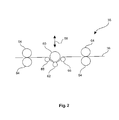
- an S-roll can be understood to mean a roll which is arranged such that the support circulates in an S-shaped manner, as is known to the person skilled in the art and described in detail below with reference to the figures.
- the carrier can be compressed in step e) by a factor of> 0% to ⁇ 7%, preferably> 0% to ⁇ 5%.
- method step e) can thus obtain a particularly smooth surface by means of a slight compression, since this method step can essentially be tuned to the smoothing or to the setting of the surface quality.
- the entire structure of the press, in particular the dual-band press can be aligned with smoothing and there is no need to focus on excessive compression, which can produce a particularly good surface image even at high throughputs.
- the invention relates to a device for producing a decorated wall or floor panel, which is characterized in that the device comprises means for performing a method configured as described above.
- the device comprises means for performing a method configured as described above.
- the invention relates to a wall or floor panel, produced according to a method described above, wherein a plate-shaped carrier has a profiling at least in one edge region.
- a profiling according to the invention it is provided that a decorative and / or functional profile is introduced by means of suitable material-removing tools at least in a part of the edges of the decorative panel.
- a functional profile for example, the introduction of a tongue and / or groove profile in an edge to understand decorative panels on the introduced Profiles connectable to each other.
- a decorative profile in the sense of the invention is, for example, a chamfer introduced in the edge region of the decorative panel in order to simulate, for example, a joint between two interconnected panels, as occurs, for example, in so-called plank flooring.
- the decorative profile to be provided in a panel such as a chamfer
- the functional profile for example tongue and groove
- the decor also corresponds to the desired imitation of a natural material, for example, in the areas of the profiling in a detailed manner.
- the print template used for printing in the area of the profiling of the panel can be distortion-compensated.
- Distortion compensation means in the context of the invention for example, for the exemplary case of application with a printing process, which is compensated by the deviation of the profiling from the surface plane of the carrier, for example at a chamfer flank, caused distortion of the printed image by adjusting the artwork to the deviation. It may be provided, for example, that the compensation of the distortion by means of adaptation the pixel spacing, the pixel size and / or the color order depending on the intended edge profile of the finished decorative panel.
- the triggering of the print head can be effected as a function of the distortion to be compensated, so that the print head is deflected beyond the profiled area, for example, and the color output is adapted to the profile.
- the joints such as V-joints
- the decorative layer is applied to the carrier profiled in this way and the carrier is then divided at least in the profiled areas.
- the type of division such as, for example, sawing, laser cutting or water jet cutting, it can preferably be provided that the required cutting allowance in the introduced profile is taken into account.
- the plate-shaped carrier may comprise a material based on a WPC material or a PVC material.
- a WPC material or a PVC material.
- the process can have further process steps in order to obtain the finished wall or floor panel.
- the device 10 according to FIG. 1 comprises first two circumferential band-like conveying means 12, 14 which are guided in particular by deflection rollers 16 such that between them a receiving space 18 for receiving and processing a provided pourable, in particular granular carrier material 20, such as based on a plastic, such as PVC, or a wood-plastic composite material, such as wood and PP, PE or a block copolymer comprising PP and PE, forms.
- the conveying means 12, 14 may be at least partially made of polytetrafluoroethylene be, for example, be coated with it.
- the conveying means 12, 14 may be at least partially roughened or structured, in particular on their side facing the receiving space 18. Further, the conveying means 12, 14 may have a width in a range of about 1.5 m.
- a discharge unit 22 is provided with one or a plurality of discharge heads 24, by means of which the carrier material 20 can be arranged on the lower conveying means 14.
- the discharge heads 24 may in this case comprise a funnel 25, which applies the carrier material 20 to corresponding scattering rollers 26, whereupon the carrier material 20 can be scattered onto the lower conveying means 14.
- a sensor for checking the arrangement of the carrier material 20 between two belt-like conveying means 12, 14 may be provided.
- the sensor may in particular be coupled to the discharge unit 22 in order to directly correct a potentially inaccurate filling of the receiving space 18.
- vibrators may also be provided. These can act approximately on the lower conveyor 14 and be arranged, for example, under the lower conveyor 14, so that the carrier material 20 is finely distributed.
- a device for introducing a fiber material into the receiving space 18 and thus be provided in the carrier can be designed like a belt and unwound from a roll.
- the fiber material may be arranged approximately between two discharge heads 24 in order, for example, to be able to arrange a different material above and below the fiber material.
- the fiber material can be introduced, for example, such that above and below the fiber material, a desired amount of support material 20 is located.
- a forming unit 28 is further provided, which is adapted to the carrier material 20 under the action of temperature or heat to fuse the carrier material 20 to form a web-shaped carrier 36 to shape.
- the molding unit 28 can have approximately two plate-like molding devices 30, 32, which can be heated by a heating device 34, for example by means of a thermal oil.
- the support material 20 may be heated until, depending on the melting point of the support material 20 or a part thereof, a temperature of, for example and depending on the material used, such as PVC or a WPV material, ⁇ 180 ° C to ⁇ 200 ° C has reached.
- the molding unit 28 or the molding devices 30, 32 can be heated, for example to a temperature of up to 250 ° C.
- one or a plurality of independently adjustable heating areas can be provided for setting a temperature gradient.
- the entire shaping devices 30, 32 which may have a length of several meters, may be heatable, or only part of them may be heatable.
- the molding unit 28 may in particular have a parallel gap, which may be formed by the plate-like molding devices 30, 32.
- an inlet mouth can be provided at the inlet by a conical shape to an improved inlet of the carrier material 20.
- the force acting on the carrier material 20 may be fed in a range from> 0 kg / m 2, up to ⁇ 1 kg / m 2.
- a uniform pressurization without the provision of a pressure profile or a pressure gradient can be provided.
- the lower former 32 is longer than the upper former 30 and also begins before the upper. It can thereby be achieved that processing only takes place when the carrier material 20 has already been melted or at least melted on and at least partially softened. As a result, a particularly defined shaping process can be made possible.
- the pressing device 38 may for example comprise an S-roll, which in detail in the FIG. 2 is shown.
- the S-roll can be moved substantially perpendicular to the surface of the carrier 36 and thus to the direction of travel of the carrier 36, as indicated by the arrow 58, so that the desired pressures can be particularly advantageous adjustable.
- the pressing device 38 may, for example, on the carrier 36 exert a pressure that may be in a range of ⁇ 1kg / m 2 to ⁇ 3kg / m 2 .
- the S-roll comprises a main roller 60, which acts on the web-shaped carrier 36.
- the belt tension may be sufficient as a back pressure, but it is preferred that at least one counter-pressure roller 62 is provided.
- two pairs of calender rolls 64 and, optionally, deflection rolls 66 can also be provided, which can furthermore provide for a suitable strip tension.
- the main roller 60 may be wrapped by the sheet-shaped carrier 36 in a range of about 50% or more.
- the temperature of the carrier 36 In addition, in the case of an inlet into the pressing device 38, in particular, the temperature present at the exit from the forming unit 28 corresponds.
- the carrier 36 is subsequently guided to a further pressing device 40.
- another heater 42 such as an IR heater, may be provided between the press devices 38, 40.
- this advantageously can be a two-belt press, which in particular can have steel belts 44, 46 and wherein the belts 44, 46 of the two-belt press can be guided by deflection rollers 48, 50.
- the deflection rollers 48, 50 can be heated, for example by means of a thermal oil heater and / or the rollers on the same side of the gap can be arranged approximately a distance in a range of ⁇ 1m to ⁇ 2m, for example 1.5m from each other, wherein the Bands 44, 46 may have a width in a range of about 1.5m.
- the carrier 20 located between the conveying means 12, 14 is guided between the deflection rollers 48, 50 and thus between the belts 44, 46, in particular steel belts.
- each pressing and / or heating means 52, 54 are provided on the carrier 36 opposite side of the bands 44, 46.
- These can both the conveyors 12, 14 and thus the carrier 36 both heat, as well as slightly compress.
- an air heater may be provided and a plurality of rollers, which may allow an intermittent pressing.
- a temperature in a range of up to 250 ° C act on the carrier 36.
- the temperature may be in a range from ⁇ 25 ° C to ⁇ 35 ° C above the melting temperature or softening temperature of the support material or a part thereof.
- such a pressure on the support 36 can act, that the carrier 36 is compressed at step e) by a factor of ⁇ 7.5%, preferably ⁇ 5%, for setting in a range of 0.2 mm to ⁇ ⁇ 0,1mm ,
- the pressing and / or heating devices 52, 54 may occupy substantially the entire area between the deflection rollers 48, 50, or even a limited area along the conveying direction.
- the carrier After passing through the pressing device 40, the carrier may have a temperature in the range of approximately 190 ° C.
- the pressing device 40 may have a variable pressure profile, starting approximately with 6mm and ending with 4.1mm, or advantageously designed as an isochronous press.
- a cooling device 56 is arranged, through which the carrier can be cooled to a temperature which is for example in a range of ⁇ 35 ° C.
- the cooling device 56 may be based, for example, on a water cooling system and include a plurality of cooling zones, in order to allow a defined cooling using precisely customizable cooling programs.
- the length of the cooling zone can correspond to the effective length of the pressing device 40. After the cooling device 56 may still be provided another cooling belt.
- the support which may have a final thickness in a range of ⁇ 3 mm to ⁇ 5 mm, for example 4.1 mm, can be treated further directly, or be stored, for example as a web-shaped carrier 36 or as an already singly plate-shaped carrier.
Abstract
Verfahren zur Herstellung eines dekorierten Wand- oder Bodenpaneels, aufweisend die Verfahrensschritte: a) Bereitstellen eines schüttfähigen Trägermaterials (20), b) Anordnen des Trägermaterials (20) zwischen zwei bandartigen Fördermitteln (12, 14), c) Formen des Trägermaterials (20) unter Temperatureinwirkung unter Ausbildung eines bahnförmigen Trägers (36), d) Komprimieren des Trägers (36), e) Behandeln des Trägers (36) unter Einwirkung von Temperatur und Druck, f) Abkühlen des Trägers (36), h) Aufbringen eines eine Dekorvorlage nachbildenden Dekors auf den Träger (36), und i) Aufbringen einer Schutzschicht auf den Dekor. Dieses Verfahren erlaubt ein besonders effektives Herstellen eines Paneels, wobei das Paneel besonders stabil, adaptierbar und hochwertig sein kann. Ferner sind vorgesehen eine Vorrichtung zur Herstellung eines dekorierten Wand- oder Bodenpaneels sowie ein Wand- oder Bodenpaneel, welches gemäß dem Verfahren hergestellt ist, wobei ein plattenförmiger Träger (36) zumindest in einem Randbereich eine Profilierung aufweist.Method for producing a decorated wall or floor panel, comprising the method steps: a) providing a pourable carrier material (20), b) arranging the carrier material (20) between two belt-like conveying means (12, 14), c) shaping the carrier material (20) under the effect of temperature to form a web-shaped carrier (36), d) compressing the carrier (36), e) treating the carrier (36) under the action of temperature and pressure, f) cooling the carrier (36), h) applying a decorative pattern replicating decoration on the carrier (36), and i) applying a protective layer to the decor. This method allows a particularly effective production of a panel, wherein the panel can be particularly stable, adaptable and high quality. Furthermore, provision is made for a device for producing a decorated wall panel or floor panel as well as a wall or floor panel which is produced according to the method, wherein a panel-shaped support (36) has a profiling at least in one edge area.
Description
Die vorliegende Erfindung betrifft ein Verfahren zum Herstellen eines dekorierten Wand- oder Bodenpaneels, eine Vorrichtung zum Herstellen eines dekorierten Wand- oder Bodenpaneels sowie ein gemäß einem solchen Verfahren hergestelltes Wand- oder Bodenpaneel.The present invention relates to a method for producing a decorated wall or floor panel, to an apparatus for producing a decorated wall or floor panel, and to a wall or floor panel produced according to such a method.
Dekorierte Platten sind an sich bekannt, wobei unter dem Begriff Wandpaneel auch Paneele zu verstehen sind, die zur Deckenbekleidung geeignet sind. Sie bestehen üblicherweise aus einem Träger beziehungsweise Kern aus einem festen Material, beispielsweise einem Holzwerkstoff, der auf mindestens einer Seite mit einer Dekorschicht und einer Deckschicht sowie gegebenenfalls mit weiteren Schichten, beispielsweise einer zwischen Dekor- und Deckschicht angeordneten Verschleißschicht, versehen ist. Die Dekorschicht ist üblicherweise ein gedrucktes Papier, das mit einem Harz imprägniert ist. Auch die Deckschicht und die übrigen Schichten werden meist aus Harz hergestellt.Decorated panels are known per se, whereby the term wall panel is also to be understood as panels which are suitable for ceiling clothing. They usually consist of a carrier or core made of a solid material, for example a wood material, which is provided on at least one side with a decorative layer and a cover layer and optionally with other layers, for example, arranged between the decorative and cover layer wear layer. The decorative layer is usually a printed paper impregnated with a resin. The top layer and the remaining layers are usually made of resin.
Die Herstellung der Paneele wie beispielsweise des Kerns beziehungsweise des Trägers kann dabei unter Umständen noch Verbesserungspotential bieten.The production of the panels such as the core or the carrier may possibly still offer room for improvement.
Es ist daher die Aufgabe der vorliegenden Erfindung, ein verbessertes Verfahren zur Herstellung von dekorierten Wand- oder Bodenpaneelen bereitzustellen.It is therefore the object of the present invention to provide an improved method for producing decorated wall or floor panels.
Gelöst wird diese Aufgabe durch ein Verfahren gemäß Anspruch 1 und durch eine Vorrichtung gemäß Anspruch 13. Hinsichtlich des Wand- oder Bodenpaneels wird die Aufgabe durch ein Paneel gemäß Anspruch 14 gelöst.This object is achieved by a method according to claim 1 and by an apparatus according to
Mit der Erfindung wird somit ein Verfahren zur Herstellung eines dekorierten Wand- oder Bodenpaneels vorgeschlagen, aufweisend die Verfahrensschritte:
- a) Bereitstellen eines schüttfähigen Trägermaterials, insbesondere eines Granulats,
- b) Anordnen des Trägermaterials zwischen zwei bandartigen Fördermitteln,
- c) Formen des Trägermaterials unter Einwirkung von Temperatur unter Ausbildung eines bahnförmigen Trägers,
- d) Komprimieren des Trägers,
- e) Behandeln des Trägers unter Einwirkung von Temperatur und Druck, insbesondere unter Verwendung einer Zweibandpresse,
- f) Abkühlen des Trägers,
- g) gegebenenfalls Aufbringen eines Dekoruntergrunds auf zumindest einen Teilbereich des Trägers;
- h) Aufbringen eines eine Dekorvorlage nachbildenden Dekors auf zumindest einen Teilbereich des Trägers,
- i) Aufbringen einer Schutzschicht auf zumindest einen Teilbereich des Dekors,
- j) gegebenenfalls Strukturieren der Schutzschicht zum Einfügen von Poren und/oder des Randbereichs des Trägers zum Ausbilden von Verbindungselementen, und
- k) gegebenenfalls Behandeln des Trägers zur elektrostatischen Entladung vor einem der vorgenannten Verfahrensschritte.
- a) providing a pourable carrier material, in particular a granulate,
- b) arranging the carrier material between two belt-like conveying means,
- c) shaping the support material under the action of temperature to form a web-shaped support,
- d) compressing the carrier,
- e) treating the support under the action of temperature and pressure, in particular using a two-band press,
- f) cooling the carrier,
- g) optionally applying a decorative substrate to at least a portion of the carrier;
- h) application of a decorative pattern reproducing decoration on at least a portion of the carrier,
- i) applying a protective layer to at least a portion of the decoration,
- j) optionally structuring the protective layer for inserting pores and / or the edge region of the carrier for forming connecting elements, and
- k) optionally treating the carrier for electrostatic discharge before one of the aforementioned method steps.
Unter dem Begriff "dekoriertes Wand- oder Bodenpaneel" beziehungsweise "Dekorpaneel" sind im Sinne der Erfindung insbesondere Wand-, Decken, oder Bodenpannele zu verstehen, welche ein auf eine Trägerplatte aufgebrachtes eine Dekorvorlage nachbildendes Dekor aufweisen. Dekorpaneele werden dabei in vielfältiger Weise sowohl im Bereich des Innenausbaus von Räumen, als auch zur dekorativen Verkleidung von Bauten, beispielsweise im Messebau, verwendet. Eine der häufigsten Einsatzbereiche von Dekorpaneelen ist deren Nutzung als Fußbodenbelag. Die Dekorpaneele weisen dabei vielfach ein Dekor auf, welches einen Naturwerkstoff nachempfinden soll.The term "decorated wall or floor panel" or "decorative panel" is to be understood in the context of the invention, in particular wall, ceiling or floor panels, which have a applied to a support plate a decorative template replica decor. Decorative panels are used in a variety of ways, both in the field of interior design of rooms, as well as decorative cladding of buildings, for example in exhibition construction. One of the most common uses of decorative panels is their use as floor coverings. The decorative panels often have a decor that is intended to recreate a natural material.
Beispiele für solche nachempfundenen Naturwerkstoffe beziehungsweise Dekorvorlagen sind Holzarten wie beispielsweise Ahorn, Eiche, Birke, Kirsche, Esche, Nussbaum, Kastanie, Wenge oder auch exotische Hölzer wie Panga-Panga, Mahagoni, Bambus und Bubinga. Darüber hinaus werden vielfach Naturwerkstoffe wir Steinoberflächen oder Keramikoberflächen nachempfunden.Examples of such modeled natural materials or decorative patterns are wood species such as maple, oak, birch, cherry, ash, walnut, chestnut, wenge or exotic woods such as panga panga, mahogany, bamboo and bubinga. In addition, many natural materials are modeled on stone surfaces or ceramic surfaces.
Entsprechend kann unter einer "Dekorvorlage" im Sinne der vorliegenden insbesondere verstanden werden ein derartiger originaler Naturwerkstoff beziehungsweise zumindest eine Oberfläche eines solchen, der durch das Dekor imitiert beziehungsweise nachempfunden werden soll.Correspondingly, a "decor template" in the sense of the present invention may be understood as meaning, in particular, such an original natural material or at least a surface of one which is to be imitated or imitated by the decor.
Unter einem "schüttfähigen" Material kann insbesondere ein Material verstanden werden, welches durch einen Schüttvorgang beziehungsweise Streuvorgang auf eine Unterlage aufgebracht werden kann. Dabei kann das Material als Fluid vorliegen oder insbesondere als schüttfähiger Feststoff.A "pourable" material may, in particular, be understood as meaning a material which can be applied to a substrate by a pouring process or spreading process. In this case, the material may be present as a fluid or in particular as a pourable solid.
Ferner kann unter einem "Granulat" beziehungsweise einem "granularen Material" ein Feststoff beziehungsweise ein Haufwerk eines Feststoffs verstanden werden, welcher eine Vielzahl fester Partikel, wie etwa Körner oder Kugeln, umfasst beziehungsweise daraus besteht. Beispielhaft aber nicht abschließend seien hier körnige oder pulverförmige Materialien genannt.Furthermore, a "granulate" or a "granular material" can be understood as meaning a solid or a heap of a solid which comprises or consists of a multiplicity of solid particles, such as grains or spheres. By way of example, but not exhaustive, granular or pulverulent materials may be mentioned here.
Unter einem "Träger" kann insbesondere eine in einem fertig gestellten Paneel als Kern beziehungsweise als Basislage dienende Lage verstanden werden, die insbesondere einen Naturstoff, wie etwa einen Holzwerkstoff, einen Faserwerkstoff oder einen Werkstoff umfassend einen Kunststoff aufweisen kann. Beispielsweise kann der Träger dem Paneel bereits eine geeignete Stabilität verleihen oder zu dieser beitragen.A "support" may in particular be understood as a layer serving as a core or as a base layer in a finished panel, which may in particular comprise a natural material, such as a wood-based material, a fiber material or a material comprising a plastic. For example, the wearer may already impart or contribute to the panel a suitable stability.
Unter einem "bahnartigen Träger" kann dabei ein Träger verstanden werden, der etwa in seinem Herstellungsprozess eine bahnartige und damit im Vergleich zu seiner Dicke beziehungsweise Breite deutlich größere Länge aufweist und deren Länge beispielsweise größer als 15 Meter betragen kann.A "web-like carrier" may be understood to mean a carrier which, in its production process, has a web-like and therefore significantly greater length compared to its thickness or width and whose length may be, for example, greater than 15 meters.
Unter einem "plattenförmigen Träger" kann dabei ferner im Sinne der vorliegenden Erfindung ein Träger verstanden werden, der durch Vereinzelung aus dem bahnartigen Träger geformt ist und in der Form einer Platte ausgebildet ist. Ferner kann der plattenförmige Träger bereits die Form und/oder Größe des herzustellenden Paneels vorgeben. Jedoch kann der plattenförmige Träger auch als Großplatte vorgesehen sein. Eine Großplatte im Sinne der Erfindung ist dabei insbesondere ein Träger, dessen Abmessungen die Abmessungen der letztendlichen Dekorpaneele um ein mehrfaches überschreiten und welche im Laufe des Herstellungsverfahrens in eine entsprechende Mehrzahl von Dekorpaneelen zerteilt wird, beispielsweise durch Sägen, Laser- oder Wasserstrahlschneiden. Beispielsweise kann die Großplatte dem bahnförmigen Träger entsprechen.In the context of the present invention, a "plate-shaped carrier" can also be understood to mean a carrier which is formed by singulation from the web-like carrier and is designed in the form of a plate. Furthermore, the plate-shaped carrier already pretend the shape and / or size of the panel to be produced. However, the plate-shaped carrier may also be provided as a large plate. A large plate according to the invention is in particular a carrier whose dimensions exceed the dimensions of the final decorative panels by a multiple and which is divided in the course of the manufacturing process into a corresponding plurality of decorative panels, for example by sawing, laser or water jet cutting. For example, the large plate can correspond to the web-shaped carrier.
"Holzwerkstoffe" im Sinne der Erfindung sind dabei neben Vollholzwerkstoffen auch Materialien wie beispielsweise Brettsperrholz, Brettschichtholz, Stabsperrholz, Funiersperrholz, Furnierschichtholz, Funierstreifenholz und Biegesperrholz. Darüber hinaus sind unter Holzwerkstoffen im Sinne der Erfindung auch Holzspanwerkstoffe wie beispielsweise Spanpressplatten, Strangpressplatten, Grobspanplatten (Oriented Structural Board, OSB) und Spanstreifenholz sowie auch Holzfaserwerkstoffe wie beispielsweise Holzfaserdämmplatten (HFD), mittelharte und harte Faserplatten (MB, HFH), sowie insbesondere mitteldichte Faserplatten (MDF) und hochdichte Faserplatten (HDF) zu verstehen. Auch moderne Holzwerkstoffe wie Holz-Polymer-Werkstoffe (Wood Plastic Composite, WPC), Sandwichplatten aus einem leichten Kernmaterial wie Schaumstoff, Hartschaum oder Papierwaben und einer darauf aufgebrachten Holzschicht, sowie mineralisch, beispielsweise mit Zement, gebundene Holzspanplatten bilden Holzwerkstoffe im Sinne der Erfindung. Auch Kork stellt dabei einen Holzwerkstoff im Sinne der Erfindung dar."Wood materials" in the context of the invention are in addition to solid wood materials such as cross-laminated timber, glued laminated timber, hardwood plywood, plywood, laminated veneer lumber, Funierstreifenholz and bending plywood. In addition, under wood materials in the context of the invention, wood chip materials such as chipboard, extruded plates, coarse chipboard (Oriented Structural Board, OSB) and chipboard wood as well as wood fiber materials such as wood fiber insulation boards (HFD), medium-hard and hard fiberboard (MB, HFH), and especially medium-density fiberboard (MDF) and high-density fiberboard (HDF) to understand. Also modern wood materials such as wood-polymer materials (WPC), sandwich panels of a lightweight core material such as foam, rigid foam or paper honeycomb and a wood layer applied thereto, as well as mineral, such as cement, bonded wood chipboard form wood materials in the context of the invention. Cork also represents a wood material in the context of the invention.
Im Sinne der Erfindung sind unter dem Begriff "Faserwerkstoffe" Materialien wie beispielsweise Papier und Vliese auf Basis pflanzlicher, tierischer, mineralischer oder auch künstlicher Fasern zu verstehen, ebenso wie Pappen. Beispiele sind Faserwerkstoffe aus pflanzlichen Fasern und neben Papieren und Vliesen aus Zellstofffasern Platten aus Biomasse wie Stroh, Maisstroh, Bambus, Laub, Algenextrakte, Hanf, Baumwolle oder Ölpalmenfasern. Beispiele für tierische Faserwerkstoffe sind etwa keratinbasierte Materialien wie beispielsweise Wolle oder Rosshaar. Beispiele für mineralische Faserwerkstoffe sind aus Mineralwolle oder Glaswolle.For the purposes of the invention, the term "fiber materials" means materials such as paper and nonwovens based on vegetable, animal, mineral or even artificial fibers, as well as cardboard. Examples are fiber materials made of vegetable fibers and in addition to papers and webs of cellulose fibers plates of biomass such as straw, corn straw, bamboo, foliage, algae extracts, hemp, cotton or oil palm fibers. Examples of animal fiber materials include keratin-based materials such as wool or horsehair. Examples of mineral fiber materials are mineral wool or glass wool.
Es konnte überraschender Weise gezeigt werden, dass es durch das vorbeschriebene Verfahren ermöglicht werden kann, eine besonders vorteilhafte Herstellung insbesondere eines Trägers eines Wand- oder Bodenpaneels zu kombinieren mit Materialien, welche zur Herstellung des Trägers des Paneels aufgrund ihrer herausragenden Eigenschaften besonders bevorzugt sind. Dabei kann durch eine Kombination der vorbeschriebenen Verfahrensschritte ein Herstellungsverfahren insbesondere eines Trägers mit herausragenden Materialien eines dekorierten Wand- oder Bodenpaneels mit einer verbesserten Effektivität ermöglicht werden, welches Verfahren darüber hinaus das Erzeugen höchst adaptierbarer und sehr stabiler Paneele erlaubt. Somit lassen sich auf einfache Weise Paneele erzeugen, welche bevorzugte Eigenschaften aufweisen können.It has surprisingly been possible to demonstrate that the method described above makes it possible to combine a particularly advantageous preparation, in particular of a carrier of a wall or floor panel, with materials which are particularly preferred for producing the carrier of the panel due to their outstanding properties. In this case, by a combination of the above-described method steps, a production method, in particular a carrier with outstanding materials of a decorated wall or floor panel can be made possible with improved effectiveness, which method moreover makes the production highly adaptable and very stable Panels allowed. Thus, it is easy to produce panels which may have preferred properties.
Das Verfahren zur Herstellung eines Wand- oder Bodenpaneels umfasst die folgenden Verfahrensschritte.The method for producing a wall or floor panel comprises the following method steps.
Zunächst wird gemäß dem vorliegenden Verfahren ein Träger beziehungsweise ein Kern erzeugt. Das vorbeschriebene Verfahren umfasst hierfür gemäß Verfahrensschritt a) zunächst das Bereitstellen eines schüttfähigen Trägermaterials. Das Trägermaterial dient als Basis zur Herstellung von insbesondere plattenförmigen Trägern für Paneele. Es kann beispielsweise als einheitliches Material vorliegen oder auch als Materialmischung aus zwei oder mehreren Materialien. Dabei sollte das Trägermaterial oder zumindest ein Bestandteil des Trägermaterials einen Schmelzpunkt oder einen Erweichungspunkt aufweisen, um das Trägermaterial in einem weiteren Verfahrensschritt durch Hitzeeinwirkung zu Formen, wie dies nachstehend im Detail erläutert ist. In besonders vorteilhafter Weise kann das Trägermaterial als schüttfähiger Feststoff beziehungsweise als Granulat bereitgestellt werden, wobei das Granulat in Abhängigkeit des verwendeten Materials rein beispielhaft etwa eine Korngröße in einem Bereich von ≥ 100 µm bis ≤ 10mm aufweisen kann. Dies ermöglicht eine problemlose Lagerfähigkeit und ferner eine besonders gute Adaptierbarkeit an eine gewünschte Materialzusammensetzung. Denn insbesondere in granularer Form kann eine besonders homogene Mischung verschiedener Bestandteile erzeugt werden, wobei eine besonders definierte Mischung mit einer genau einstellbaren Zusammensetzung erhältlich ist. Beispielhaft können sogenannte Dryblends verwendet werden, also trockene Kunststoffpulver mit Zuschlagstoffen. Darüber hinaus lässt sich ein Granulat insbesondere in dem vorbeschriebenen Größenbereich sehr homogen und ferner sehr definiert auf einem Untergrund verteilen, so dass sich ein Träger mit einem höchst definierten Eigenschaftsprofil erzeugen lässt. Eine bevorzugte Schüttung beziehungsweise Verteilung des Trägermaterials kann dabei eine Abweichung der Schüttdichte von ≤5%, insbesondere < 3% aufweisen. Gemäß Verfahrensschritt b) wird das schüttfähige, insbesondere granulare, Trägermaterial zwischen zwei bandartigen Fördermitteln angeordnet. Im Detail wird ein unteres bandartiges Fördermittel umlaufend verfahren und in einem definierten Abstand zu dem unteren Fördermittel wird ein oberes bandartiges Fördermittel umlaufend verfahren. Das Trägermaterial kann so auf das untere Fördermittel aufgebracht werden und anschließend durch das untere und das obere Fördermittel begrenzt werden. Durch eine exakte Streuung kann dabei auf eine seitliche Begrenzung verzichtet werden. Durch die beiden Fördermittel kann das Trägermaterial somit zu beziehungsweise durch einzelne Bearbeitungsstationen gefördert und zu einem Träger verarbeitet werden. Weiterhin kann das Trägermaterial bereits in diesem Verfahrensschritt vorgeformt werden. Somit können die bandartigen Fördermittel zwei Funktionen übernehmen, nämlich die eines Transportmittels und die einer Form.First, according to the present method, a carrier or a core is generated. For this purpose, the above-described method comprises according to method step a) first of all providing a pourable carrier material. The carrier material serves as the basis for the production of in particular plate-shaped carriers for panels. It may be present, for example, as a uniform material or as a material mixture of two or more materials. In this case, the support material or at least one constituent of the support material should have a melting point or a softening point in order to form the support material in a further process step by the action of heat, as explained in detail below. In a particularly advantageous manner, the support material can be provided as a pourable solid or as granules, wherein the granules can have a grain size in a range of ≥ 100 microns to ≤ 10 mm purely by way of example, depending on the material used. This allows a problem-free storage life and also a particularly good adaptability to a desired material composition. In particular, in granular form, a particularly homogeneous mixture of various components can be produced, with a particularly defined mixture is obtainable with a precisely adjustable composition. By way of example, so-called dry blends can be used, ie dry plastic powders with additives. In addition, granules can be distributed very homogeneously and furthermore very clearly distributed on a substrate, in particular in the above-described size range, so that a carrier with a highly defined property profile can be produced. A preferred bed or distribution of the support material may have a deviation of the bulk density of ≤5%, in particular < 3%. According to process step b), the pourable, in particular granular, carrier material is arranged between two belt-like conveying means. In detail, a lower belt-like conveyor is circulating and at a defined distance from the lower conveyor an upper belt-like conveyor is moved circumferentially. The carrier material can be applied to the lower conveyor and then limited by the lower and the upper conveyor. By an exact scattering can be dispensed with a lateral boundary. By means of the two conveying means, the carrier material can thus be conveyed to or through individual processing stations and processed into a carrier. Furthermore, the carrier material can already be preformed in this process step. Thus, the belt-like conveying means can take on two functions, namely that of a means of transport and that of a mold.
Dabei können die bandartigen Fördermittel zumindest teilweise aus Teflon beziehungsweise aus Polytetrafluorethylen (PTFE) ausgestaltet sein. Beispielsweise können die Bänder vollständig aus Polytetrafluorethylen geformt sein, oder es können Bänder verwendet werden, welche mit einer Außenbeschichtung aus Polytetrafluorethylen versehen sind. In letzterem Fall können etwa glasfaserverstärkte Kunststoffbänder Verwendung finden. Durch derartige Fördermittel kann aufgrund der Antihafteigenschaften dieses Werkstoffs eine besonders definierte beispielsweise glatte Oberfläche des erzeugten Trägers erzeugbar sein. So kann verhindert werden, dass das geförderte Trägermaterial an den Fördermitteln anhaftet und so die Oberflächenstruktur unmittelbar oder durch anhaftendes Material in einem nächsten Zyklus negativ beeinflusst. Darüber hinaus ist Polyterafluorethylen auch bei hohen Temperaturen beständig gegen Chemikalien wie auch gegen eine Zersetzung, so dass zum Einen eine problemlose Temperaturbehandlung des Trägermaterials möglich ist und die Fördermittel ferner auch für einen langen Zeitraum stabil sind. Darüber hinaus kann das Trägermaterial frei wählbar sein.The band-like conveying means may be at least partially made of Teflon or polytetrafluoroethylene (PTFE). For example, the bands may be formed entirely of polytetrafluoroethylene, or bands provided with an outer coating of polytetrafluoroethylene may be used. In the latter case, glass fiber reinforced plastic tapes can be used. By means of such conveying means, a particularly defined, for example, smooth surface of the carrier produced can be produced on account of the non-stick properties of this material. Thus it can be prevented that the conveyed carrier material adheres to the conveying means and thus adversely affects the surface structure directly or by adhering material in a next cycle. In addition, polyterafluoroethylene is resistant to chemicals as well as against decomposition even at high temperatures, so that on the one hand a problem-free temperature treatment of the carrier material is possible and the funding is also stable for a long period of time. In addition, the carrier material can be freely selectable.
Das Austragen des Trägermaterials gemäß Verfahrensschritt b) kann dabei insbesondere mittels eines oder einer Mehrzahl an Streuköpfen realisierbar sein, welche das Trägermaterial definiert austragen können. Bezüglich der Streuköpfe können diese beispielsweise Bestandteil eines Streuaggregats sein und wenigstens eine rotierende Streuwalze aufweisen. Beispielsweise kann ein Trichter vorgesehen sein, der das auszutragende Material definiert auf die Streuwalze austragen kann. Dabei kann ferner ein Rakel vorgesehen sein, welches das Material in Vertiefungen der Walze streicht. Anschließend kann das Material mit Hilfe einer rotierenden Bürstwalze aus der Streuwalze ausgetragen werden, wobei es gegen eine Prallfläche trifft und von dort auf das Fördermittel gleitet. Um die Streubreite zu regulieren kann ferner eine Streubreiteneinstellung vorgesehen sein. In dieser Ausgestaltung kann ein besonders homogenes Austragen des Trägermaterials erfolgen, was gleichermaßen zu einem homogenen Träger mit definierter Qualität führen kann.The discharging of the carrier material according to method step b) can be realized in particular by means of one or a plurality of scattering heads, which can discharge the carrier material in a defined manner. With regard to the scattering heads, these may for example be part of a scattering unit and have at least one rotating scattering roller. For example, a funnel can be provided, which can carry out the material to be discharged defined on the scattering roller. In this case, a doctor may further be provided which sweeps the material in recesses of the roller. Subsequently, the material can be discharged by means of a rotating brush roller from the scattering roller, where it hits against a baffle and from there slides on the conveyor. In order to regulate the spread, a spread width setting may be further provided. In this embodiment, a particularly homogeneous discharge of the carrier material can take place, which can likewise lead to a homogeneous carrier with defined quality.
Beispielsweise kann ein Streukopf oder können zwei, drei oder mehr Streuköpfe vorgesehen sein. Dadurch kann der Träger auf besonders einfache Weise besonders maßschneiderbar sein, indem beispielsweise eine gewünschte Materialmischung bereitgestellt werden kann. In dieser Ausgestaltung kann die Mischung problemlos während des Herstellungsprozesses oder zwischen zwei Chargen angepasst werden, so dass eine besonders große Variabilität sichergestellt werden kann. Darüber hinaus kann durch eine unterschiedliche Bestückung der einzelnen Streuköpfe eine Mischung für das Trägermaterial erst unmittelbar vor der Verarbeitung erzeugt werden, so dass eine negative Beeinflussung der verschiedenen Komponenten untereinander und eine dadurch bedingte Verringerung der Qualität des hergestellten Trägers verhindert werden kann.For example, a scattering head or two, three or more scattering heads can be provided. As a result, the carrier can be particularly tailor-made in a particularly simple manner, for example by providing a desired material mixture. In this embodiment, the mixture can be easily adapted during the manufacturing process or between batches, so that a particularly large variability can be ensured. In addition, by a different equipping of the individual scattering heads, a mixture for the carrier material can be generated only immediately before processing, so that a negative influence on the various components with each other and a consequent reduction in the quality of the carrier produced can be prevented.
In einem weiteren Schritt erfolgt gemäß Verfahrensschritt c) ein Formen des zwischen den bandartigen Fördermitteln angeordneten Trägermaterials unter Einwirkung von Temperatur beziehungsweise Wärme. In diesem Verfahrensschritt erfolgt durch die einwirkende Wärme beziehungsweise Hitze somit ein Aufschmelzen beziehungsweise Erweichen des Trägermaterials oder zumindest eines Teils desselben, wodurch beispielsweise das Granulat formbar werden kann. In diesem Zustand kann es den zwischen den Fördermitteln sich ausbildenden Aufnahmeraum homogen ausfüllen und so einen bahnförmigen Träger ausbilden, der weiter behandelt werden kann.In a further step, according to method step c), a shaping of the carrier material arranged between the band-like conveying means takes place under the action of temperature or heat. In this process step takes place by the acting heat or heat thus melting or softening of Support material or at least a part thereof, whereby, for example, the granules can be formed. In this state, it can homogeneously fill the receiving space forming between the conveying means and thus form a web-shaped carrier which can be further treated.
Der so ausgebildete bahnförmige Träger kann folgend gemäß Verfahrensschritt d) komprimiert werden. Dieser Verfahrensschritt kann insbesondere in einer geeigneten Presse beziehungsweise Walze erfolgen. Es erfolgt hier somit ein erstes Verdichten des bahnförmigen Trägers. Bei diesem Schritt kann der Träger bereits im Wesentlichen seine gewünschte Dicke erhalten, so dass bei folgenden Bearbeitungsschritten lediglich ein geringfügiges Verdichten erfolgen braucht und die weiteren Schritte somit besonders schonend verlaufen können, wie dies nachstehend im Detail erläutert wird. Dabei kann insbesondere sichergestellt werden, dass die Temperatur des Trägers soweit abgekühlt ist, dass eine geeignete Komprimierbarkeit unter Erhalt des gewünschten Ergebnisses ermöglicht werden kann.The thus formed web-shaped carrier can be compressed according to method step d) below. This process step can be carried out in particular in a suitable press or roller. There is thus here a first compression of the web-shaped carrier. In this step, the carrier can already essentially obtain its desired thickness, so that in the following processing steps only a slight compression needs to take place and thus the further steps can be particularly gentle, as will be explained in detail below. In this case, it can be ensured, in particular, that the temperature of the carrier has cooled down so far that a suitable compressibility can be achieved while maintaining the desired result.
In einem weiteren Verfahrensschritt e) erfolgt nun ein weiteres Behandeln des Trägers unter Einwirkung von Temperatur beziehungsweise Wärme und Druck, insbesondere unter Verwendung einer Zweibandpresse. In diesem Verfahrensschritt können insbesondere die Oberflächeneigenschaften des Trägers eingestellt werden. Beispielsweise kann in diesem Verfahrensschritt insbesondere eine Glättung der Oberfläche erfolgen. Hierzu kann der zuvor verdichtete Träger unter Einwirkung von Temperatur und Druck behandelt werden, wobei insbesondere der Druck gering gewählt werden kann derart, dass diese zweite Komprimierung lediglich in einem sehr geringen Bereich stattfindet. Beispielhaft kann eine Komprimierung in einem Bereich von ≤5%, insbesondere < 3% der Gesamtdicke des Trägers vor dem Komprimieren erfolgen. Somit kann die Ausgestaltung der Bearbeitungsvorrichtung in diesem Verfahrensschritt insbesondere gewählt werden in Abhängigkeit einer gewünschten Einstellung der Oberflächeneigenschaften, was besonders schonend sein kann.In a further method step e), a further treatment of the carrier takes place under the action of temperature or heat and pressure, in particular using a two-band press. In particular, the surface properties of the carrier can be adjusted in this method step. For example, in this process step, in particular a smoothing of the surface can take place. For this purpose, the previously compressed carrier can be treated under the action of temperature and pressure, wherein in particular the pressure can be selected low such that this second compression takes place only in a very small range. By way of example, a compression in a range of ≤5%, carried out in particular <3% of the total thickness of the carrier before compression. Thus, the configuration of the processing device in this process step can be chosen in particular depending on a desired adjustment of the surface properties, which can be particularly gentle.
Dabei kann insbesondere das Verwenden einer Zweibandpresse von Vorteil sein, da mit einer derartigen Presse besonders schonende Komprimierungsschritte möglich sind und ferner die Oberflächengüte besonders effektiv und definiert eingestellt werden kann. Weiterhin kann insbesondere das Verwenden einer Bandpresse hohe Liniengeschwindigkeiten ermöglichen, so dass der gesamte Prozess einen besonders hohen Durchlauf ermöglichen kann.In particular, the use of a two-belt press may be advantageous, since particularly gentle compression steps are possible with such a press, and furthermore the surface quality can be adjusted in a particularly effective and defined manner. Furthermore, in particular, the use of a belt press can enable high line speeds, so that the entire process can enable a particularly high throughput.
Beispielsweise kann eine derartige Bandpresse, welche meist einen recht langen Bearbeitungsraum in der Förderrichtung des Trägers aufweist, eine Mehrzahl von Temperierzonen aufweisen, was ein Temperaturprofil und damit eine effektive Einstellung der Oberflächeneigenschaften auch bei hohen Liniengeschwindigkeiten erlauben kann.For example, such a belt press, which usually has a fairly long processing space in the conveying direction of the carrier, have a plurality of tempering zones, which may allow a temperature profile and thus an effective adjustment of the surface properties even at high line speeds.
Darüber hinaus kann etwa durch das Vorsehen von Pneumatikzylindern eine besonders gleichmäßige und definiert einstellbare Bandspannung der Zweibandpresse ermöglicht werden, so dass die Einstellung der Oberflächengüte wie auch der Komprimierung besonders exakt sein kann. Die Bandpresse kann dabei etwa Stahlbänder umfassen und etwa durch eine Thermalölheizung temperierbar sein.In addition, a particularly uniform and defined adjustable belt tension of the two-band press can be made possible by the provision of pneumatic cylinders, for example, so that the adjustment of the surface quality as well as the compression can be particularly exact. The belt press can include about steel bands and be tempered by a thermal oil heating.
Ein Glätten beiziehungsweise das Einstellen der Oberflächengüte kann dabei in diesem Schritt bedeuten, dass zwar die oberste Oberfläche geglättet wird, etwa bereits eingebrachte Strukturen beziehungsweise Poren jedoch nicht oder nur in einem definierten Bereich beeinflusst werden, so dass diese auch nach diesem Verfahrensschritt noch in gewünschter Weise vorliegen können, insoweit dies erwünscht ist. Dies kann insbesondere durch die Verwendung einer Bandpresse mit geeignetem Temperaturprofil und mit geeigneten Druckwerten ermöglicht werden.Smoothing or adjusting the surface finish may mean in this step that, although the uppermost surface is smoothed, already introduced structures or pores, however, are not or only influenced within a defined range, so that they still remain in the desired manner after this process step may be present, insofar as this is desired. This can be made possible in particular by the use of a belt press with a suitable temperature profile and with suitable pressure values.
Im weiteren Verlauf erfolgt in einem weiteren Verfahrensschritt f) anschließend ein Abkühlen des bahnförmigen Trägers. Der Träger kann insbesondere durch das Vorsehen einerIn the further course, cooling of the web-shaped carrier takes place in a further method step f). The carrier can in particular by the provision of a
Kühlvorrichtung mit definierten Kühlstufen auf eine Temperatur abgekühlt werden, welche der Raumtemperatur entspricht oder rein beispielhaft in einem Bereich von bis zu 20°C darüber liegt. Beispielsweise kann eine Mehrzahl an Kühlzonen vorliegen, um ein definiertes Abkühlen des Trägers zu ermöglichen.Cooling device can be cooled with defined cooling stages to a temperature which corresponds to the room temperature or is purely exemplary in a range of up to 20 ° C above. For example, there may be a plurality of cooling zones to allow for defined cooling of the support.
Nach einem Abkühlen des erzeugten Trägers kann der Träger zunächst in bahnartiger Form oder als vereinzelte plattenartige Träger gelagert werden und das Verfahren kann zunächst beendet sein. Vorzugsweise schließen sich jedoch unmittelbar weitere Behandlungsschritte an, welche etwa ohne ein Anschleifen realisierbar sein können, insbesondere um den bereitgestellten Träger derart zu bearbeiten, um ein fertiges Paneel zu erzeugen, wie dies nachstehend im Detail erläutert ist.After cooling of the carrier produced, the carrier can first be stored in a web-like form or as an isolated plate-like carrier, and the process can initially be completed. Preferably, however, immediately follow further treatment steps, which may be feasible without grinding, in particular in order to process the provided support so as to produce a finished panel, as explained in detail below.
Zur Herstellung eines fertigen Paneels umfasst das Verfahren die weiteren folgenden Verfahrensschritte, um den Träger mit einem Dekor zu versehen und dieses mit einer Schutzschicht zu beschichten. Dabei werden die nachfolgenden Schritte bevorzugt unmittelbar mit dem erzeugten bahnförmigen Träger durchgeführt. Es ist von der Erfindung jedoch ebenfalls mit umfasst, dass der bahnförmige Träger vor einem der Verfahrensschritte g) bis j) zunächst in eine Vielzahl plattenförmiger Träger unterteilt wird und/oder der plattenförmigen Träger durch die entsprechend folgenden Verfahrensschritte weiter behandelt wird. Die nachstehenden Erläuterungen gelten für beide Alternativen entsprechend, wobei zur Vereinfachung im Weiteren von einer Behandlung des Trägers gesprochen wird.To produce a finished panel, the method comprises the further following method steps in order to provide the support with a decoration and to coat it with a protective layer. The subsequent steps are preferably carried out directly with the web-shaped carrier produced. However, it is also encompassed by the invention that the web-shaped carrier is first subdivided into a plurality of plate-shaped carriers prior to one of method steps g) to j) and / or the plate-shaped carrier is further processed by the corresponding following method steps. The following explanations apply to both alternatives, with a further discussion of treatment of the carrier for the sake of simplicity.
Gemäß Verfahrensschritt gk) kann somit gegebenenfalls zunächst etwa vor dem Verfahrensschritt g) ein Vorbehandeln des Trägers zur elektrostatischen Entladung erfolgen. Dies kann insbesondere dazu dienen, das Auftreten von Unschärfen im Laufe der Dekoraufbringung zu vermeiden. Dies ist insbesondere für Druckverfahren zum Aufbringen der Dekorschichten geeignet, da die sich im Laufe des Produktionsprozesses aufbauende elektrostatische Ladung in den zu bedruckenden Trägern zu einer Ablenkung der Farb- bzw. Tintentropfen auf ihrem Weg vom Druckkopf zur der zu bedruckenden Oberfläche führt. Die so hervorgerufene Ungenauigkeit des Farbauftrags führt zu der wahrnehmbaren Unschärfe des Druckbildes.According to process step gk), pretreatment of the carrier for electrostatic discharge can thus optionally first be carried out, for example, before process step g). This may in particular serve to avoid the occurrence of blurring in the course of decor application. This is particularly suitable for printing methods for applying the decorative layers, since the build up in the course of the production process electrostatic charge in the substrates to be printed to a deflection of the color or Drops of ink on their way from the print head to the surface to be printed. The thus caused inaccuracy of the ink application leads to the noticeable blurring of the printed image.
Dabei kann die Einrichtung zur Ableitung elektrostatischer Ladungen wenigstens eine Rolle, Bürste oder Lippe aus einem leitfähigen Material mit einer Leitfähigkeit ≥ 1*103 Sm-1 aufweisen, welche den Träger zumindest im Bereich des Druckwerks elektrisch leitend kontaktiert und welche mit einem elektrischen Massenpotential verbunden ist. Dabei kann das elektrische Massenpotential beispielsweise durch eine Erdung bereitgestellt werden. Ferner kann eine Einrichtung zur Ableitung elektrostatischer Ladungen beispielsweise eine Einrichtung zur Erzeugung einer Corona-Entladung sein.In this case, the means for discharging electrostatic charges may comprise at least one roller, brush or lip of a conductive material with a conductivity ≥ 1 * 10 3 Sm -1 , which electrically conductively contacts the carrier at least in the area of the printing unit and which is connected to an electrical ground potential is. In this case, the electrical ground potential can be provided for example by a ground. Furthermore, a device for discharging electrostatic charges may be, for example, a device for generating a corona discharge.
Gemäß Verfahrensschritt g) kann weiterhin gegebenenfalls ein Dekoruntergrund auf zumindest einen Teilbereich des Trägers aufgebracht werden. Beispielsweise kann zunächst ein Primer insbesondere für Druckverfahren als Dekoruntergrund aufgebracht werden, etwa in einer Dicke von ≥ 10µm bis ≤ 60 µm. Dabei kann als Primer eine flüssige strahlungshärtende Mischung auf Basis eines Urethans oder eines Urethanacrylats, gegebenenfalls mit einem oder mehreren von einem Photoinitiator, einem Reaktivverdünner, einem UV-Stabilisator, einem Rheologiemittel wie einem Verdicker, Radikalfänger, Verlaufshilfsmittel, Entschäumer oder Konservierungsmittel, Pigment und/oder einem Farbstoff eingesetzt werden. Beispielsweise kann das Urethanacrylat in Form von reaktiven Oligomeren bzw. Prepolymeren in der Primer-Zusammensetzung enthalten sein. Unter dem Begriff "reaktives Oligomer" bzw. "Prepolymer" ist dabei im Sinne der Erfindung eine Urethanacrylat-Einheiten aufweisende Verbindung zu verstehen, welche strahlungsinduziert, ggf. unter Zusatz eines reaktiven Bindemittels oder eines Reaktiwerdünners zu Urethan-Polymer oder Urethanacrylat-Polymer reagieren kann. Urethanacrylate im Sinne der Erfindung sind dabei Verbindungen, welche im Wesentlichen aus einem oder mehreren aliphatischen Strukturelementen und Urethangruppen aufgebaut sind. Aliphatische Strukturelemente umfassen sowohl Alkylengruppen, vorzugsweise mit 4 bis 10 C-Atomen, als auch Cycloalkylengruppen mit vorzugsweise 6 bis 20 C-Atomen. Sowohl die Alkylen- als auch die Cycloalkylengruppen können mit C1-C4-Alkyl, insbesondere mit Methyl, ein- oder mehrfach substituiert sein sowie ein oder mehrere nicht benachbarte Sauerstoffatome enthalten. Die aliphatischen Strukturelemente sind gegebenenfalls überquartäre oder tertiäre Kohlenstoffatome, über Harnstoffgruppen, Biureth-, Urethdion-, Allophanat-, Cyanurat-, Urethan-, Ester- oder Amidgruppen oder über Ethersauerstoff oder Aminstickstoff miteinander verbunden. Ferner können Urethanacrylate im Sinne der Erfindung auch ethylenisch ungesättigte Strukturelemente aufweisen. Hierbei handelt es sich vorzugsweise um Vinyl- oder Allylgruppen, die auch mit C1-C4-Alkyl, insbesondere Methyl substituiert sein können und welche sich insbesondere von α,β-ethylenisch ungesättigten Carbonsäuren bzw. deren Amiden ableiten. Besonders bevorzugte ethylenisch ungesättigte Struktureinheiten sind Acryloyl- und Me-thacryloylgruppen wie Acrylamido und Methacrylamido und insbesondere Acryloxy und Methacryloxy. Strahlungshärtbar im Sinne der Erfindung bedeutet, dass die Primerzusammensetzung induziert durch elektromagnetische Strahlung geeigneter Wellenlänge, wie beispielsweise UV-Strahlung, oder Elektronenstrahlung zumindest teilpolymerisiert werden kann.According to method step g), a decorative substrate may furthermore optionally be applied to at least one partial region of the carrier. For example, initially a primer can be applied in particular for printing processes as a decorative substrate, for example in a thickness of ≥ 10 μm to ≦ 60 μm. In this case, the primer used may be a liquid radiation-curing mixture based on a urethane or a urethane acrylate, optionally with one or more of a photoinitiator, a reactive diluent, a UV stabilizer, a rheology agent such as a thickener, radical scavenger, leveling agent, defoamer or preservative, pigment and / or or a dye. For example, the urethane acrylate can be contained in the form of reactive oligomers or prepolymers in the primer composition. For the purposes of the invention, the term "reactive oligomer" or "prepolymer" is to be understood as meaning a compound comprising urethane acrylate units, which may be radiation-induced, possibly reactive to urethane polymer or urethane acrylate polymer with the addition of a reactive binder or reactive diluent , Urethane acrylates in the context of the invention are compounds which are essentially composed of one or more aliphatic structural elements and urethane groups. Aliphatic structural elements include both Alkylene groups, preferably having 4 to 10 C-atoms, as well as cycloalkylene groups having preferably 6 to 20 C-atoms. Both the alkylene and the cycloalkylene groups may be mono- or polysubstituted with C 1 -C 4 -alkyl, in particular with methyl, and may contain one or more non-adjacent oxygen atoms. The aliphatic structural elements are optionally connected to each other via quaternary or tertiary carbon atoms, via urea groups, biuret, urethdione, allophanate, cyanurate, urethane, ester or amide groups or via ether oxygen or amine nitrogen. Furthermore, urethane acrylates according to the invention may also have ethylenically unsaturated structural elements. These are preferably vinyl or allyl groups which may also be substituted by C 1 -C 4 -alkyl, in particular methyl, and which are derived in particular from α, β-ethylenically unsaturated carboxylic acids or their amides. Particularly preferred ethylenically unsaturated structural units are acryloyl and methacryloyl groups such as acrylamido and methacrylamido and especially acryloxy and methacryloxy. Radiation-curable in the sense of the invention means that the primer composition can be at least partially polymerized, induced by electromagnetic radiation of a suitable wavelength, such as, for example, UV radiation, or electron radiation.
Die Verwendung von strahlungshärtbaren Primern auf Basis von Urethanacrylaten ermöglicht in besonders vorteilhafter Weise eine sich umgehend an den Auftrag und die strahlungsinduzierte Härtung der Primerschicht anschließende Aufbringung eines Dekor, beispielsweise mittel Digitaldrucktechnik. Dabei sorgt die Primerschicht für eine gute Haftung des aufgebrachten Dekors auf der mit dem Primer beschichteten Trägeroberfläche. Dabei besitzen Urethanacrylate den Vorteil einer guten Haftung sowohl gegenüber dem Trägermaterial, als auch gegenüber der Dekorschicht, also der Dekorfarbe oder -tinte. Dies ist unter anderem durch die bei dieser Art der Polymere auftretenden Polymerisationsreaktionen zu begründen, bei welcher zum einen eine strahlungsinduzierte radikalische Polymerisation der OH-Gruppen auftritt, zum anderen eine Nachhärtung des Polymers über die NCO-Gruppen. Dies führt dazu, dass nach der strahlungsinduzierten Härtung umgehend eine klebfreie und weiterbearbeitbare Oberfläche erhalten wird, während die endgültigen Eigenschaften der Primerschicht auch durch die NCO-Gruppen basierte Nachhärtung beeinflusst werden und für eine sichere Bindung zum Trägermaterial sorgen. Darüber hinaus stellt die auftretende Nachhärtung sicher, dass eine hinreichende Schichtstabilität auch in weniger oder nicht belichteten Bereichen des Trägers erreicht wird. Hierdurch lassen sich mit dem erfindungsgemäßen Verfahren insbesondere auch vorstrukturierte Träger, also Träger, deren Oberfläche bereits eine dreidimensionale Strukturierung aufweisen, sicher mit Primerschicht versehen, wodurch sichergestellt ist, dass das anschließend aufgebrachte Dekor haftfest mit dem Träger verbunden ist.The use of radiation-curable primers based on urethane acrylates makes it possible in a particularly advantageous manner to apply a decoration, for example by means of digital printing technology, immediately following the application and the radiation-induced curing of the primer layer. The primer layer ensures good adhesion of the applied decoration on the carrier surface coated with the primer. In this case, urethane acrylates have the advantage of good adhesion both to the support material and to the decorative layer, ie the decorative color or ink. This is due inter alia to the polymerization reactions occurring in this type of polymers, in which on the one hand a radiation-induced radical polymerization of the OH groups occurs, on the other hand, a post-curing of the polymer via the NCO groups. This leads to the fact that immediately after the radiation-induced curing non-tacky and processable surface, while the final properties of the primer layer are also affected by NCO group-based post cure and provide secure bonding to the substrate. In addition, the postcuring that occurs ensures that sufficient layer stability is achieved even in less or unexposed areas of the support. In this way, in particular, pre-structured carriers, ie carriers whose surface already has a three-dimensional structuring, can be provided with a primer layer with the method according to the invention, which ensures that the subsequently applied decoration is adhesively bonded to the carrier.
Der Primer kann im erfindungsgemäßen Verfahren bevorzugt mittels Gummiwalzen, Gießmaschine oder durch Aufsprühen auf die Trägerplatte aufgebracht werden. Bevorzugt wird der Primer in einer Menge zwischen ≥1g/m2 und ≤100 g/m2, vorzugsweise zwischen ≥10 g/m2 und ≤50 g/m2, insbesondere zwischen ≥20 g/m2 und ≤40 g/m2 aufgetragen. Im Anschluss an den Auftrag des Primers auf die Trägeroberfläche erfolgt eine Bestrahlung mit einer Strahlungsquelle geeigneter Wellenlänge.The primer can preferably be applied in the process according to the invention by means of rubber rollers, casting machine or by spraying onto the carrier plate. The primer is preferably used in an amount between ≥ 1 g / m 2 and ≦ 100 g / m 2 , preferably between ≥ 10 g / m 2 and ≦ 50 g / m 2 , in particular between ≥ 20 g / m 2 and ≦ 40 g / m 2 applied. Following the application of the primer to the carrier surface, irradiation is carried out with a radiation source of suitable wavelength.
Neben der Verwendung eines Primer ist es möglich, das Dekor auf ein mit einem entsprechenden Dekor bedruckbares Dekorpapier aufzubringen, welches etwa mittels einer zuvor auf den Träger aufgebrachten Harzschicht als Verbindungsmittel vorgesehen sein kann. Ein derartiger Druckuntergrund ist sowohl für Flexo-Druck, Offset-Druck oder Siebdruckverfahren, als auch insbesondere für Digitaldrucktechniken, wie beispielsweise Inkjet-Verfahren oder Laserdruck-Verfahren geeignet. Zur Aufbringung der Harzschicht kann es vorzugsweise vorgesehen sein, dass eine Harzzusammensetzung aufgebracht wird, welche als Harzkomponente wenigstens eine Verbindung ausgewählt aus der Gruppe bestehend aus Melaminharz, Formaldehydharz, Harnstoffharz, Phenolharz, Epoxidharz, ungesättigtes Polyesterharz, Diallylphthalat oder Mischungen dieser aufweist. Dabei kann die Harzzusammensetzung beispielsweise in einer Auftragsmenge zwischen ≥5 g/m2 und ≤40 g/m2, vorzugsweise ≥10 g/m2 und ≤30 g/m2 aufgetragen werden. Ferner kann ein Papier oder Vlies mit einer Grammatur zwischen ≥30 g/m2 und ≤80 g/m2, vorzugsweise zwischen ≥40 g/m2 und ≤70 g/m2 auf den plattenförmigen Träger aufgebracht.In addition to the use of a primer, it is possible to apply the decor to a decorative paper which can be printed with a corresponding decor, which can be provided as a connection means, for example, by means of a resin layer previously applied to the support. Such a printing substrate is suitable both for flexo printing, offset printing or screen printing methods, and in particular for digital printing techniques, such as inkjet method or laser printing method. For applying the resin layer, it may be preferable to apply a resin composition having as a resin component at least one compound selected from the group consisting of melamine resin, formaldehyde resin, urea resin, phenol resin, epoxy resin, unsaturated polyester resin, diallyl phthalate, or mixtures thereof. In this case, the resin composition may be, for example, in an application amount between ≥5 g / m 2 and ≤40 g / m 2 , preferably ≥10 g / m 2 and ≤30 g / m 2 are applied. Furthermore, a paper or nonwoven having a grammage of between ≥ 30 g / m 2 and ≦ 80 g / m 2 , preferably between ≥ 40 g / m 2 and ≦ 70 g / m 2, may be applied to the plate-shaped carrier.
Weiterhin kann gemäß Verfahrensschritt h) ein Aufbringen eines eine Dekorvorlage nachbildenden Dekors auf zumindest einen Teilbereich des Trägers erfolgen. Dabei kann das Dekor durch den sogenannten Direktdruck aufgebracht werden. Unter dem Begriff "Direktdruck" wird im Sinne der Erfindung das Aufbringen eines Dekors direkt auf den Träger eines Paneels oder auf eine auf dem Träger aufgebrachte nicht bedruckte Faserwerkstoffschicht beziehungsweise ein Dekoruntergrund verstanden. Es können unterschiedliche Drucktechniken, wie beispielsweise Flexo-Druck, Offset-Druck oder Siebdruck zum Einsatz gelangen. Insbesondere können als Digitaldrucktechniken beispielsweise Inkjet-Verfahren oder Laserdruck-Verfahren eingesetzt werden.Furthermore, in accordance with method step h), a decoration which imitates a decorative pattern can be applied to at least one subregion of the carrier. The decor can be applied by the so-called direct printing. For the purposes of the invention, the term "direct printing" refers to the application of a decoration directly to the support of a panel or to a non-printed fibrous material layer or a decorative substrate applied to the support. Different printing techniques, such as flexographic printing, offset printing or screen printing can be used. In particular, as digital printing techniques, for example, inkjet method or laser printing method can be used.
Beispielsweise kann, um eine Dekorvorlage auf besonders detailgetreue und hochgenaue Weise in dreidimensionaler Form zu imitieren beziehungsweise nach zu empfinden, Das Dekor vorlagenidentisch aufgebracht werden. Insbesondere können die dreidimensionalen Dekordaten bereitgestellt werden durch ein dreidimensionales Abtasten der Dekorvorlage mittels elektromagnetischer Strahlung, beispielsweise durch einen dreidimensionalen Scanner (3D-Scanner). Dabei können eine Mehrzahl an Dekorschichten mit zumindest teilweise unterschiedlichem Flächenauftrag auf Basis bereitgestellter dreidimensionaler Dekordaten sukzessive aufgebracht wird.For example, to imitate a decorative template in a particularly detailed and highly accurate manner in three-dimensional form or to feel the same, the decor can be applied identical to a template. In particular, the three-dimensional decor data can be provided by a three-dimensional scanning of the decor template by means of electromagnetic radiation, for example by a three-dimensional scanner (3D scanner). In this case, a plurality of decorative layers with at least partially different surface application based on provided three-dimensional decor data can be applied successively.
Ferner können die Dekorschichten aus einer insbesondere strahlungshärtbaren Farbe und/oder Tinte ausgebildet werden. Beispielsweise kann eine UV-härtbare Farbe oder Tinte verwendet werden. In dieser Ausgestaltung kann eine besonders detailgetreue und übereinstimmende Nachbildung der Dekorvorlage erreichbar sein. Denn zum Einen kann auf diese Weise ohne das Vorsehen weiterer Maßnahmen und hochgenau eine Synchronpore erzielbar sein. Eine Synchronpore kann dabei insbesondere eine Pore oder eine andersartige Struktur sein, welche räumlich exakt dort angeordnet ist, wo sie optisch dargestellt ist durch ein mit dem optischen Dekormerkmalen übereinstimmenden haptischen Strukturierung. Dies ist im Wesentlichen in dieser Ausgestaltung automatisch der Fall, da die strukturelle Ausgestaltung eben durch die Farbe beziehungsweise Tinte erzeugt wird. Darüber hinaus weisen Dekorvorlagen, wie beispielsweise Holzwerkstoffe, oftmals eine Variation des Farbeindrucks nicht nur entlang ihrer Breite beziehungsweise Länge sondern ebenfalls entlang ihrer Tiefe auf. Auch dieser Farbeindruck beziehungsweise Farbverlauf kann insbesondere in dieser Ausgestaltung besonders detailgetreu nachempfunden werden, was auch den Gesamteindruck des Paneels noch identischer erscheinen lässt. Dabei lässt sich insbesondere dann, wenn die verwendete Farbe beziehungsweise Tinte strahlungshärtbar ist, eine besonders schnelle Verfestigung erreichen, wodurch die Mehrzahl an Schichten schnell aufeinander aufbringbar sein können, was auch den Gesamtprozess in einer geringeren Zeit realisierbar und damit besonders kostengünstig gestalten kann.Furthermore, the decorative layers can be formed from a particular radiation-curable ink and / or ink. For example, a UV-curable ink or ink may be used. In this embodiment, a particularly detailed and consistent replica of the decorative template can be achieved. For one thing, in this way can be achieved without the provision of further measures and highly accurate a synchronous pore. A Synchronous pore can be in particular a pore or a different type of structure, which is spatially arranged exactly where it is optically represented by a matching with the optical decor features haptic structuring. This is essentially the case automatically in this refinement, since the structural design is precisely produced by the ink or ink. In addition, decor templates, such as wood-based panels, often have a variation of the color impression not only along their width or length but also along their depth. Also, this color impression or color gradient can be modeled in particular detail in this embodiment, which also makes the overall impression of the panel appear even more identical. In this case, especially when the ink or ink used is radiation-curable, a particularly rapid solidification can be achieved, as a result of which the plurality of layers can be rapidly applied to one another, which can also make the overall process feasible in a shorter time and thus more cost-effective.
Unter dem Begriff strahlungshärtbare Farbe ist dabei im Sinne der Erfindung eine binde- und/oder füllmittelmittelhaltige sowie Farbpigmente aufweisende Zusammensetzung zu verstehen, welche induziert durch elektromagnetische Strahlung geeigneter Wellenlänge, wie beispielsweise UV-Strahlung oder Elektronenstrahlung, zumindest teilpolymerisiert werden kann.In the context of the invention, the term radiation-curable ink is understood to mean a composition containing binder and / or filler as well as color pigments, which can be at least partially polymerized induced by electromagnetic radiation of suitable wavelength, such as UV radiation or electron radiation.
Unter dem Begriff strahlungshärtbare Tinte ist dabei entsprechend im Sinne der Erfindung eine im Wesentlichen Füllmittel freie, Farbpigmente aufweisende Zusammensetzung zu verstehen, welche induziert durch elektromagnetische Strahlung geeigneter Wellenlänge, wie beispielsweise UV-Strahlung oder Elektronenstrahlung, zumindest teilpolymerisiert werden kann.According to the invention, the term radiation-curable ink is to be understood as meaning a substantially filler-free, color pigments-containing composition which can be at least partially polymerized induced by electromagnetic radiation of suitable wavelength, such as UV radiation or electron radiation.
Dabei können die Dekorschichten jeweils in einer Dicke in einem Bereich von ≥ 5 µm bis ≤ 10 µm aufgebracht werden.In this case, the decorative layers can each be applied in a thickness in a range of ≥ 5 μm to ≦ 10 μm.
Es kann ferner vorgesehen sein, neben einer bezüglich Farbe und/oder Struktur positiven Abbildung ferner auch eine entsprechende negative Abbildung der Dekorvorlage aufzubringen. Im Detail kann, wie es beispielsweise von einem Positiv-Beizen beziehungsweise Negativ-Beizen für Holzwerkstoffe bekannt ist, durch die Verwendung von digitalen Daten der Farbeindruck beispielsweise einer Maserung umgekehrt werden, so dass bezüglich der Farbe beziehungsweise insbesondere helleren und dunkleren Bereichen ein Negativ entsteht. Entsprechendes ist neben dem Farbeindruck ebenfalls für die aufgebrachte Struktur möglich, so dass auch bezüglich der strukturellen Ausgestaltung ein Negativ realisierbar ist. Auch derartige Effekte sind auf Basis digitaler dreidimensionaler Daten problemlos und ohne Vorlaufzeit beziehungsweise Umbauten in einen Herstellungsprozess integrierbar.It can also be provided, in addition to a color and / or structure positive image also apply a corresponding negative image of the decor template. In detail, as is known, for example, from a positive pickling or negative pickling for wood materials, the color impression of, for example, a grain can be reversed by the use of digital data, so that a negative arises with respect to the color or, in particular, lighter and darker areas. The same is possible in addition to the color impression also for the applied structure, so that also with respect to the structural design, a negative is feasible. Even such effects can be easily integrated into a production process on the basis of digital three-dimensional data without any lead time or conversions.
Gemäß Verfahrensschritt i) kann ein Aufbringen einer Schutzschicht auf zumindest einen Teilbereich des Dekors vorgesehen sein. Eine derartige Schicht zum Schutz des aufgebrachten Dekors kann insbesondere als Verschleiß- oder Deckschicht oberhalb der Dekorschicht in einem nachfolgenden Verfahrensschritt aufgebracht werden, welche insbesondere die Dekorschicht vor Abnutzung oder Beschädigung durch Schmutz, Feuchtigkeitseinfluss oder mechanische Einwirkungen, wie beispielsweise Abrieb, schützt. Beispielsweise kann es vorgesehen sein, dass die Verschleiß- und/oder Deckschicht als vorproduzierte Overlayschicht, etwa basierend auf Melamin, auf den bedruckten Träger aufgelegt und mit diesem durch Druck- und/oder Wärmeeinwirkung verbunden wird. Ferner kann es bevorzugt sein, dass zur Ausbildung der Verschleiß- und/oder Deckschicht ebenfalls eine strahlungshärtbare Zusammensetzung, wie beispielsweise ein strahlungshärtbarer Lack, wie einem Acryllack, aufgebracht wird. Dabei kann es vorgesehen sein, dass die Verschleißschicht Hartstoffe wie beispielsweise Titannitrid, Titancarbid, Siliciumnitrid, Siliciumcarbid, Borcarbid, Wolframcarbid, Tantalcarbid, Aluminiumoxid (Korund), Zirconiumoxid oder Mischungen dieser aufweist, um die Verschleißfestigkeit der Schicht zu erhöhen. Dabei kann die Auftragung beispielsweise mittels Walzen, wie Gummiwalzen oder mittels Gießvorrichtungen aufgetragen werden.According to method step i), a coating of a protective layer on at least a portion of the decoration may be provided. Such a layer for protecting the applied decoration can be applied in particular as a wear or cover layer above the decorative layer in a subsequent process step, which in particular protects the decorative layer from wear or damage by dirt, moisture or mechanical effects such as abrasion. For example, it may be provided that the wear and / or cover layer is laid on the printed support as a pre-produced overlay layer, for example based on melamine, and connected thereto by pressure and / or heat. Furthermore, it may be preferred that a radiation-curable composition, such as, for example, a radiation-curable lacquer, such as an acrylic lacquer, is also applied to form the wear and / or cover layer. It may be provided that the wear layer hard materials such as titanium nitride, titanium carbide, silicon nitride, Silicon carbide, boron carbide, tungsten carbide, tantalum carbide, alumina (corundum), zirconium oxide or mixtures thereof, to increase the wear resistance of the layer. In this case, the application can be applied for example by means of rollers, such as rubber rollers or by means of pouring devices.
Weiterhin kann die Deckschicht zunächst teilgehärtet werden und im Anschluss eine Endlackierung mit einem Urethanacrylat und eine Endhärtung, etwa mit einem Galliumstrahler, durchgeführt werden.Furthermore, the cover layer can first be partially cured and subsequently a final coating with a urethane acrylate and a final curing, such as with a gallium radiator, are performed.
Ferner kann die Deck- und/oder Verschleißschicht Mittel zur Verringerung der statischen (elektrostatischen) Aufladung des letztendlichen Laminates aufweisen. Beispielsweise kann es dazu vorgesehen sein, dass die Deck- und/oder Verschleißschicht Verbindungen wie z.B. Cholinchlorid aufweist. Das Antistatikmittel kann dabei beispielsweise in einer Konzentration zwischen ≥0,1 Gew.-% und ≤40,0 Gew.-%, bevorzugt zwischen ≥1,0 Gew.-% und ≤30,0 Gew.-% in der Deck- und/oder Zusammensetzung zur Ausbildung Verschleißschicht enthalten sein.Further, the cover and / or wear layer may include means for reducing the static (electrostatic) charge of the final laminate. For example, it can be provided that the cover and / or wearing layer compounds such. Choline chloride has. The antistatic agent may, for example, in a concentration between ≥0.1 wt .-% and ≤40.0 wt .-%, preferably between ≥1.0 wt .-% and ≤30.0 wt .-% in the cover and / or composition for forming wear layer.
Desweiteren kann es gemäß Verfahrensschritt j) vorgesehen, dass in die Schutzschicht beziehungsweise Verschleiß- oder Deckschicht eine Strukturierung, insbesondere eine mit dem Dekor übereinstimmende Oberflächenstrukturierung durch das Einbringen von Poren eingebracht wird. Dabei kann es vorgesehen sein, dass die Trägerplatte bereits eine Strukturierung aufweist und eine Ausrichtung eines Druckwerkzeuges zur Aufbringung des Dekors und der Trägerplatte zueinander in Abhängigkeit mittels der mittels optischer Verfahren erfassten Strukturierung der Trägerplatte erfolgt. Zur Ausrichtung des Druckwerkzeuges und der Trägerplatte zueinander kann es dabei vorgesehen sein, dass eine zur Ausrichtung notwendige Relativbewegung zwischen Druckwerkzeug und Trägerplatte zueinander durch eine Verschiebung der Trägerplatte oder durch eine Verschiebung des Druckwerkzeugs erfolgt. Weiterhin kann es vorgesehen sein, dass eine Strukturierung der Dekorpaneele nach dem Auftrag der Deck- und/oder Verschleißschicht erfolgt. Hierzu kann es bevorzugt vorgesehen sein, dass als Deck- und/oder Verschleißschicht eine härtbare Zusammensetzung aufgetragen wird und ein Aushärtungsprozess nur in dem Maße erfolgt, dass lediglich eine Teilhärtung der Deck- und/oder Verschleißschicht erfolgt. In die so teilgehärtete Schicht wird mittels geeigneter Werkzeuge, wie beispielsweise einer Hartmetall-Strukturwalz oder eines Stempels, eine gewünschte Oberflächenstruktur eingeprägt. Dabei erfolgt die Prägung in Übereinstimmung mit dem aufgebrachten Dekor. Zur Gewährleistung einer hinreichenden Übereinstimmung der einzubringenden Struktur mit dem Dekor kann es vorgesehen sein, dass die Trägerplatte und das Prägewerkzeug durch entsprechende Relativbewegungen zueinander ausgerichtet werden. Im Anschluss an die Einbringung der gewünschten Struktur in die teilgehärtete Deck- und/oder Verschleißschicht erfolgt eine weitere Härtung der nun strukturierten Deck- und/oder Verschleißschicht.Furthermore, according to method step j), it is provided that a structuring, in particular a surface structuring matching the decor, is introduced into the protective layer or wear or cover layer by the introduction of pores. It can be provided that the carrier plate already has a structuring and alignment of a printing tool for applying the decor and the support plate to each other in dependence on by means of the optical process detected structuring of the support plate. For aligning the pressure tool and the support plate to each other, it may be provided that a necessary relative to the orientation relative movement between the pressure tool and support plate to each other by a displacement of the support plate or by a displacement of the pressure tool. Furthermore, it can be provided that a structuring of Decorative panels after the application of the cover and / or wear layer takes place. For this purpose, it can preferably be provided that a curable composition is applied as cover and / or wear layer and a curing process takes place only to the extent that only partial hardening of the cover and / or wear layer takes place. In the thus partially cured layer, a desired surface structure is impressed by means of suitable tools, such as a hard metal structural roll or a stamp. The embossing is done in accordance with the applied decor. In order to ensure sufficient conformity of the structure to be introduced with the decor, provision may be made for the carrier plate and the embossing tool to be aligned with one another by corresponding relative movements. Subsequent to the introduction of the desired structure into the partially cured cover and / or wear layer, a further hardening of the now structured covering and / or wear layer takes place.
Vielfach ist es vorgesehen, dass in solche Verschleiß- oder Deckschichten eine mit dem Dekor übereinstimmende Oberflächenstrukturierung eingebracht ist. Unter einer mit dem Dekor übereinstimmenden Oberflächenstrukturierung ist zu verstehen, dass die Oberfläche des Dekorpaneels eine haptisch wahrnehmbare Struktur aufweist, welche in ihrer Form und ihrem Muster dem aufgebrachten Dekor entspricht, um so eine möglichst originalgetreue Nachbildung eines natürlichen Werkstoffes auch hinsichtlich der Haptik zu erhalten.In many cases it is provided that in such wear or cover layers a matching with the decor surface structuring is introduced. Under a matching with the decor surface structuring is to be understood that the surface of the decorative panel has a haptic perceptible structure, which corresponds in shape and pattern of the applied decor, so as to obtain a true to the original reproduction of a natural material also in terms of haptics.
Darüber hinaus kann auf der der Dekorseite gegenüberliegenden Seite ein Gegenzug aufgebracht werden. Dabei ist es insbesondere bevorzugt, dass der Gegenzug in einem gemeinsamen Kalandrierschritt mit den Papier oder Vlies auf der Dekorseite aufgebracht wird.In addition, a counter-pull can be applied on the side opposite the decorative side. It is particularly preferred that the counter-pull is applied in a common calendering with the paper or non-woven on the decorative side.
Alternativ oder zusätzlich können die Randbereiche des Paneels strukturiert beziehungsweise profiliert werden, um insbesondere lösbare Verbindungselemente vorzusehen. Diesbezüglich kann bei einer Profilierung im Sinne der Erfindung vorgesehen sein, dass mittels geeigneter materialabhebender Werkzeuge zumindest in einen Teil der Kanten des Dekorpaneels ein dekoratives und/oder funktionales Profil eingebracht wird. Dabei ist unter einem funktionalen Profil beispielsweise die Einbringung eines Nut- und/oder Federprofils in eine Kante zu verstehen, um Dekorpaneele über die eingebrachten Profilierungen miteinander verbindbar zu gestalten. Insbesondere bei Nut- und/oder Federprofilen sind dabei elastische Werkstoffe von Vorteil, da durch diese allein derartige Profile erzeugbar sind, welche besonders einfach handhabbar und stabil sind. So sind insbesondere keine weiteren Materialien notwendig, um die Verbindungselemente zu erzeugen.Alternatively or additionally, the edge regions of the panel can be structured or profiled, in order to provide in particular detachable connecting elements. In this regard, it can be provided in a profiling according to the invention that by means of suitable material removal tools at least in a part of the edges of the decorative panel a decorative and / or functional profile is introduced. In this case, a functional profile is understood, for example, to mean the introduction of a tongue and / or groove profile into an edge in order to make decorative panels connectable to each other via the introduced profilings. Particularly in the case of tongue and / or groove profiles, elastic materials are advantageous, since such profiles alone can be produced by them, which are particularly easy to handle and stable. In particular, no further materials are necessary to produce the fasteners.
Das vorstehend beschriebene Verfahren ermöglicht dabei ein verbessertes Herstellen eines Wandpaneels beziehungsweise Bodenpaneels.The method described above enables an improved production of a wall panel or floor panel.
Insbesondere kann das Trägermaterial besonders frei wählbar sein und es können insbesondere Trägermaterialen Verwendung finden, welche für das herzustellende Paneel besonders vorteilhafte Eigenschaften aufweisen können. Beispielsweise können besonders hochwertige Paneele erzeugbar sein, welche bezüglich Erscheinung und Stabilität höchsten Anforderungen genügen können. Dabei kann eine Herstellung besonders effektiv und kostengünstig sein.In particular, the support material can be chosen particularly freely and, in particular, support materials can be used which can have particularly advantageous properties for the panel to be produced. For example, it is possible to produce particularly high-quality panels which can meet the highest requirements in terms of appearance and stability. In this case, a production can be particularly effective and inexpensive.
Das bei dem Verfahren zum Herstellen eines Wand- und Bodenpaneels anwendbare Verfahren zum Erzeugen eines Trägers kann dabei insbesondere im Rahmen des vorliegenden erfindungsgemäßen Verfahrens zu Herstellen von Wand- und Bodenpaneelen vorteilhaft sein, da es besonders hohe Liniengeschwindigkeiten ermöglicht, die weit über den aus dem Stand der Technik bekannten Liniengeschwindigkeiten, als einer Vorschubgeschwindigkeit des Trägers beziehungsweise der Fördermittel, für das Herstellen eines Paneels liegen können. Dabei können insbesondere durch die Verwendung einer Zweibandpresse Liniengeschwindigkeiten von bis zu 15 m/min, erzielbar sein, wobei Werte von 6m/min oder mehr auch für diesbezüglich problematische Materialien möglich sein können.The method for producing a carrier that can be used in the method for producing a wall and floor panel can be advantageous, in particular in the context of the present inventive method for producing wall and floor panels, since it enables particularly high line speeds, which far exceed those of the prior art Line speeds known to the art, as a feed rate of the carrier or the conveying means, may be for the manufacture of a panel. Line speeds of up to 15 m / min can be achieved, in particular by the use of a two-belt press, whereby values of 6 m / min or more can also be possible for materials which are problematic in this respect.
Weiterhin kann durch den vorbeschriebenen zweistufigen Komprimierungsvorgang eine sehr genaue Dicke insbesondere für Paneel-Trägermaterialien erzielbar sein, wobei beispielsweise Dickentoleranzen in einem Bereich von 0,1mm oder darunter erzielbar sein können. Somit kann ein durch das vorbeschriebene Verfahren hergestellter Träger neben einer besonders homogenen Zusammensetzung ferner eine besonders gleichmäßige Dicke aufweisen, was ein besonders definiertes und reproduzierbares Produkt und somit eine besonders hohe Qualität erlaubt.Furthermore, by the above-described two-stage compression process a very accurate thickness can be achieved, in particular for panel support materials, wherein, for example, thickness tolerances in a range of 0.1 mm or less can be achieved. Thus, in addition to a particularly homogeneous composition, a carrier produced by the above-described method can furthermore have a particularly uniform thickness, which allows a particularly defined and reproducible product and thus a particularly high quality.
Ferner konnte gefunden werden, dass insbesondere durch das vorbeschriebene Verfahren sehr stabile Träger erzeugbar sein können, welche bezüglich der Stabilität weiter verbessert sein kann.Furthermore, it has been found that in particular by the method described above very stable carriers can be produced, which can be further improved in terms of stability.
Gemäß einer Ausgestaltung kann ein Trägermaterial auf Basis eines Kunststoffs oder eines Holz-Kunststoff-Komposit-Werkstoffs (WPC) bereitgestellt werden. Beispielsweise kann die Trägerplatte aus einem thermoplastischen, elastomeren oder duroplastischen Kunststoff ausgebildet sein. Des Weiteren sind Recyclingwerkstoffe aus den genannten Materialien im Rahmen des erfindungsgemäßen Verfahrens einsetzbar. Bevorzugt als Plattenmaterial können dabei insbesondere thermoplastische Kunststoffe, wie Polyvinylchlorid, Polyolefine (beispielsweise Polyethylen (PE), Polypropylen (PP), Polyamide (PA), Polyurethane (PU), Polystyrol (PS), Acrylnitril-Butadien-Styrol (ABS), Polymethylmethacrylat (PMMA), Polycarbonat (PC), Polyethylenterephthalat (PET), Polyetheretherketon (PEEK) oder Mischungen oder Co-Polymerisate diese. Dabei können unabhängig von dem Grundmaterial des Trägers beispielsweise Weichmacher vorgesehen sein, die etwa in einem Bereich von >0 Gew.-% bis ≤ 20 Gew.-%, insbesondere < 10 Gew.-%, vorzugsweise < 7 Gew.-%, beispielsweise in einem Bereich von ≥ 5 Gew.-% bis ≤ 10 Gew.-% vorliegen können. Ein geeignete Weichmacher umfasst etwa den unter der Handelsbezeichnung "Dinsch" von der Firma BASF vertriebenen Weichmacher. Ferner können als Ersatz für herkömmliche Weichmacher Copolymere, wie etwa Acrylate oder Methacrylate, vorgesehen sein.According to one embodiment, a carrier material based on a plastic or a wood-plastic composite material (WPC) can be provided. For example, the carrier plate may be formed of a thermoplastic, elastomeric or thermosetting plastic. Furthermore, recycled materials from the materials mentioned can be used in the context of the method according to the invention. In particular, thermoplastic materials such as polyvinyl chloride, polyolefins (for example polyethylene (PE), polypropylene (PP), polyamides (PA), polyurethanes (PU), polystyrene (PS), acrylonitrile-butadiene-styrene (ABS), polymethyl methacrylate may be preferred as the plate material (PMMA), polycarbonate (PC), polyethylene terephthalate (PET), polyetheretherketone (PEEK) or mixtures or co-polymers thereof In this case, irrespective of the base material of the support, it is possible, for example, to provide plasticizers which are present in a range of> 0% by weight. % to ≦ 20% by weight, in particular < 10% by weight, preferably < 7% by weight, for example in a range from ≥ 5% by weight to ≦ 10% by weight about the under the trade name "Dinsch" of the BASF sold plasticizers. Further, as a replacement for conventional plasticizers, copolymers such as acrylates or methacrylates may be provided.
Insbesondere thermoplastische Kunststoffe bieten auch den Vorteil, dass die aus ihnen hergestellten Produkte sehr leicht rezykliert werden können. Es können auch Recycling-Materialien aus anderen Quellen verwendet werden. Hierdurch ergibt sich eine weitere Möglichkeit zur Senkung der Herstellungskosten.In particular, thermoplastics also offer the advantage that the products made from them can be recycled very easily. Recycled materials from other sources can also be used. This results in a further possibility for reducing the production costs.
Derartige Träger sind dabei sehr elastisch beziehungsweise federnd, was einen komfortablen Eindruck beim Begehen erlaubt und ferner die auftretenden Geräusche bei einem Begehen im Vergleich zu herkömmlichen Materialien reduzieren kann, somit eine verbesserter Trittschall realisierbar sein kann.Such carriers are very elastic or resilient, which allows a comfortable impression when walking and also can reduce the noise occurring when committing compared to conventional materials, thus an improved footfall sound can be realized.
Darüber hinaus bieten die vorgenannten Träger den Vorteil einer guten Wasserfestigkeit, da sie eine Quellung von 1 % oder weniger aufweisen. Dies gilt in überraschender Weise neben reinen Kunststoffträgern auch für WPC-Werkstoffe, wie diese nachfolgend im Detail erläutert sind.Moreover, the above-mentioned carriers offer the advantage of good water resistance since they have a swelling of 1% or less. This is true in a surprising way in addition to pure plastic substrates for WPC materials, as they are explained in detail below.
In besonders vorteilhafter Weise kann das Trägermaterial Holz-Polymer-Werkstoffe (Wood Plastic Composite, WPC) aufweisen oder daraus bestehen. Hier kann beispielhaft ein Holz und ein Polymer geeignet sein, welches in einem Verhältnis von 40/60 bis 70/30, beispielsweise 50/50 vorliegen kann. Als Polymere Bestandteile können etwa Polypropylen, Polyethylen oder ein Copolymer aus den beiden vorgenannten Materialien verwendet werden. Derartige Materialien bieten den Vorteil, dass diese bereits bei geringen Temperaturen, wie etwa in einem Bereich von ≥ 180°C bis ≤ 200°C in dem vorbeschriebenen Verfahren zu einem Träger geformt werden können, so dass eine besonders effektive Prozessführung, etwa mit beispielhaften Liniengeschwindigkeiten in einem Bereich von 6m/min, ermöglicht werden kann. Beispielsweise sind für ein WPC-Produkt mit einer 50/50 Verteilung der Holz- und Polymeranteile bei einer beispielhaften Produktstärke von 4,1mm möglich, was einen besonders effektiven Herstellungsprozess ermöglichen kann.In a particularly advantageous manner, the carrier material may comprise or consist of wood-polymer materials (WPC). Here, by way of example, a wood and a polymer may be suitable, which may be present in a ratio of 40/60 to 70/30, for example 50/50. Polypropylene, polyethylene or a copolymer of the two abovementioned materials can be used as polymer constituents. Such materials offer the advantage that they can already be formed into a support at low temperatures, such as in a range of ≥ 180 ° C. to ≦ 200 ° C., in the method described above, so that particularly effective process control, for example at exemplary line speeds in a range of 6m / min, can be made possible. For example, for a WPC product with a 50/50 distribution of wood and Polymer shares with an exemplary product thickness of 4.1mm possible, which can enable a particularly effective manufacturing process.
Ferner können so sehr stabile Paneele erzeugt werden, die weiterhin eine hohe Elastizität aufweisen, was insbesondere für eine effektive und kostengünstige Ausgestaltung von Verbindungselementen an dem Randbereich des Trägers und ferner bezüglich einer Trittschalldämmung von Vorteil sein kann. Ferner kann auch die vorgenannte gute Wasserverträglichkeit mit einer Quellung von unter 1% bei derartigen WPC-Materialien ermöglicht werden. Dabei können WPC-Werkstoffe beispielsweise Stabilisatoren und/oder andere Additive aufweisen, welche bevorzugt im Kunststoffanteil vorliegen können.Furthermore, very stable panels can be produced which furthermore have high elasticity, which can be advantageous in particular for an effective and cost-effective design of connecting elements on the edge region of the carrier and furthermore with regard to footfall sound insulation. Furthermore, the aforementioned good water compatibility can be made possible with a swelling of less than 1% in such WPC materials. In this case, WPC materials, for example, stabilizers and / or other additives, which may preferably be present in the plastic content.
Weiterhin kann es besonders vorteilhaft sein, dass das Trägermaterial ein PVC-basiertes Material umfasst oder daraus besteht. Auch derartige Materialien können in besonders vorteilhafter Weise für hochwertige Paneele dienen, welche etwa auch in Feuchträumen problemlos verwendbar sind. Ferner bieten sich auch PVC-basierte Trägermaterialien für einen besonders effektiven Herstellungsprozess an, da hier etwa Liniengeschwindigkeiten von 8m/min bei einer beispielhaften Produktstärke von 4,1mm möglich sein können, was einen besonders effektiven Herstellungsprozess ermöglichen kann. Ferner weisen auch derartige Träger eine vorteilhafte Elastizität und Wasserverträglichkeit auf, was zu den vorgenannten Vorteilen führen kann.Furthermore, it may be particularly advantageous that the carrier material comprises or consists of a PVC-based material. Also, such materials can be used in a particularly advantageous manner for high quality panels, which are easily used even in wet rooms. Furthermore, PVC-based carrier materials are also suitable for a particularly effective production process, since here line speeds of 8 m / min with an exemplary product thickness of 4.1 mm may be possible, which may allow a particularly effective production process. Furthermore, such carriers have an advantageous elasticity and water compatibility, which can lead to the aforementioned advantages.
Bei Kunststoff-basierten Paneelen wie auch bei WPC-basierten Paneelen können dabei mineralische Füllstoffe von Vorteil sein. Besonders geeignet sind hier etwa Talk oder auch Kalziumcarbonat (Kreide), Aluminiumoxid, Kieselgel, Quarzmehl, Holzmehl, Gips. Beispielsweise kann Kreide vorgesehen sein in einem Bereich von ≥ 30 Gew.-% bis ≤ 70 Gew.-%, wobei durch die Füllstoffe, insbesondere durch die Kreide insbesondere der Schlupf des Trägers verbessert werden kann. Auch können sie in bekannter Weise eingefärbt sein. Insbesondere kann es vorgesehen sein, dass das Plattenmaterial ein Flammschutzmittel aufweist.In the case of plastic-based panels as well as WPC-based panels, mineral fillers may be advantageous. Particularly suitable here are about talc or calcium carbonate (chalk), alumina, silica, quartz, wood flour, gypsum. For example, chalk can be provided in a range from ≥ 30% by weight to ≦ 70% by weight, it being possible in particular for the slips of the carrier to be improved by the fillers, in particular by the chalk. Also, they can be colored in a known manner. In particular, it may be provided that the plate material has a flame retardant.
Gemäß einer weiteren Ausgestaltung kann das Trägermaterial Mikrohohlkugeln aufweisen. Derartige Zusatzstoffe können insbesondere bewirken, dass die Dichte des Trägers und damit des erzeugten Paneels signifikant reduziert werden kann, so dass ein besonders einfacher und kostengünstiger Transport und ferner ein besonders komfortables Verlegen gewährleistet werden kann. Dabei kann insbesondere durch das Einfügen von Mikrohohlkugeln eine Stabilität des erzeugten Paneels gewährleistet werden, welche im Vergleich zu einem Material ohne Mikrohohlkugeln nicht signifikant reduziert ist. Somit ist die Stabilität für einen Großteil der Anwendungen vollkommen ausreichend. Unter Mikrohohlkugeln können dabei insbesondere Gebilde verstanden werden, welche einen hohlen Grundkörper aufweisen und eine Größe beziehungsweise einen maximalen Durchmesser aufweisen, der im Mikrometerbereich liegt. Beispielsweise können verwendbare Hohlkugeln einen Durchmesser aufweisen, welcher im Bereich von ≥ 5µm bis ≤ 100µm, beispielsweise ≥ 20µm bis ≤ 50µm liegt. Als Material der Mikrohohlkugeln kommt grundsätzlich jegliches Material in Betracht, wie beispielsweise Glas oder Keramik. Ferner können aufgrund des Gewichts Kunststoffe, etwa die auch in dem Trägermaterial verwendeten Kunststoffe, beispielsweise PVC, PE oder PP, vorteilhaft sein, wobei diese gegebenenfalls, etwa durch geeignete Zusatzstoffe, an einem Verformen während des Herstellungsverfahrens gehindert werden können.According to a further embodiment, the carrier material may comprise hollow microspheres. Such additives can in particular cause the density of the carrier and thus of the panel produced can be significantly reduced, so that a particularly simple and cost-effective transport and also a particularly comfortable installation can be guaranteed. In this case, a stability of the panel produced can be ensured in particular by the insertion of hollow microspheres, which is not significantly reduced compared to a material without hollow microspheres. Thus, stability is sufficient for most of the applications. Under hollow microspheres can be understood in particular structures that have a hollow body and have a size or a maximum diameter, which is in the micrometer range. For example, usable hollow spheres may have a diameter which is in the range of ≥ 5 μm to ≦ 100 μm, for example ≥ 20 μm to ≦ 50 μm. As a material of the hollow microspheres is basically any material into consideration, such as glass or ceramic. Furthermore, due to the weight of plastics, such as the plastics used in the support material, for example PVC, PE or PP, may be advantageous, which may optionally be prevented, for example by suitable additives, from deforming during the manufacturing process.
Gemäß einer weiteren Ausgestaltung können die bandartigen Fördermittel zumindest teilweise strukturiert sein. Durch die Verwendung von strukturierten Fördermitteln kann ein Träger erzeugbar sein, der ebenfalls strukturiert ist und somit etwa Poren aufweisen kann, die etwa ein nachzuempfindendes Naturprodukt wiederspiegeln können. Dadurch kann etwa auf eine weitere Strukturierung in dem nachfolgenden Produktionsprozess des Paneels verzichtet werden, was die nachfolgenden Verfahrensschritte besonders einfach, schnell und kostengünstig gestalten kann. Darüber hinaus kann die Strukturierung beziehungsweise können die Poren in dieser Ausgestaltung in einem Arbeitsschritt mit dem Formen des bandförmigen Trägers realisiert werden, so dass ein weiterer Arbeitsschritt für die Ausbildung der Poren entfallen kann. Weiterhin kann die eingeführte Struktur dadurch, dass sie bereits im Träger und damit im Kern des Paneels vorliegt, auch bei höchster Beanspruchung besonders stabil und langlebig sein. Neben dem Einbringen einer Struktur können die Förderbänder auch eine definierte Rauigkeit aufweisen, da so ein Entlüften bei einem Formen des Trägers verbessert werden kann. Dabei können beispielsweise für das obere und untere Band unterschiedliche Rautiefen verwendet werden, wobei das untere Band eine größere Rautiefe aufweisen kann, als das obere Band beziehungsweise bandartige Fördermittel. Beispielsweise kann das untere Band und/oder kann das obere Band eine Rautiefe in einem Bereich von ≥ 0 bis ≤ 25 µm aufweisen.According to a further embodiment, the band-like conveying means may be at least partially structured. Through the use of structured conveying means, it is possible to produce a carrier which is likewise structured and thus can have pores, for example, which can reflect a natural product to be sensed. As a result, it is possible, for example, to dispense with further structuring in the subsequent production process of the panel, which can make the subsequent method steps particularly simple, quick and cost-effective. In addition, the structuring or In this embodiment, the pores can be realized in one working step with the shaping of the band-shaped carrier, so that a further working step for the formation of the pores can be dispensed with. Furthermore, the introduced structure in that it is already present in the carrier and thus in the core of the panel, even with the highest stress be particularly stable and durable. In addition to the introduction of a structure, the conveyor belts can also have a defined roughness, since such a venting can be improved in a shaping of the carrier. In this case, for example, different roughness depths can be used for the upper and lower band, wherein the lower band can have a greater roughness depth than the upper band or band-like conveying means. For example, the lower band and / or the upper band may have a roughness depth in a range of ≥ 0 to ≦ 25 μm.
Gemäß einer weiteren Ausgestaltung kann ein Sensor zum Überprüfen des Anordnens des Trägermaterials zwischen den zwei bandartigen Fördermitteln vorgesehen sein. Insbesondere kann der Sensor das Anordnen des Trägermaterials auf dem unteren Fördermittel detektieren. Beispielsweise kann ein insbesondere auf Röntgenstrahlen basierender Sensor vorgesehen sein, der das Flächengewicht des aufgetragenen Materials und so die Homogenität des aufgetragenen Materials überprüft. Vorzugsweise kann der Sensor eine Rückkopplung zu den Streueinheiten aufweisen, um so unmittelbar auf ein fehlerhaftes Auftragen reagieren zu können. Dabei kann der Sensor durch entsprechende Schutzbleche abgeschirmt sein, um ein ungewolltes Austreten von Röntgenstrahlung zu verhindern. Ferner kann zur Schonung und zur Verlängerung Lebensdauer des Sensors ein Kühlsystem vorgesehen sein.According to a further embodiment, a sensor for checking the arrangement of the carrier material between the two belt-like conveying means may be provided. In particular, the sensor may detect the placement of the substrate on the lower conveyor. For example, it is possible to provide a sensor which is based in particular on x-rays and checks the weight per unit area of the material applied and thus the homogeneity of the material applied. Preferably, the sensor may have a feedback to the scattering units so as to be able to react immediately to a faulty application. In this case, the sensor can be shielded by appropriate fenders to prevent accidental leakage of X-rays. Furthermore, a cooling system can be provided to protect and extend the life of the sensor.
Gemäß einer weiteren Ausgestaltung kann in den Träger ein Faserwerkstoff eingearbeitet werden. Insbesondere kann der Faserwerkstoff in den Träger bei Verfahrensschritt b) eingearbeitet werden. In dieser Ausgestaltung kann somit etwa ein Faserwerkstoff, insbesondere als Faserwerkstoffbahn, auf einer Rolle aufgewickelt sein und mittels einer Abwickelstation zum Abwickeln des Faserwerkstoffs abgewickelt und zwischen die zwei bandartigen Fördermittel geführt werden, um den Faserwerkstoff einzufügen. Beispielsweise kann in dieser Ausgestaltung ein Glasfaservlies verwendet werden. In dieser Ausgestaltung kann ein Träger mit einer besonders hohen Belastbarkeit beziehungsweise Stabilität erzeugt werden, da die Festigkeit des Trägers durch den eingearbeiteten Faserwerkstoff signifikant erhöht werden kann. Darüber hinaus kann der Träger in dieser Ausgestaltung besonders maßgeschneidert werden, da beispielsweise durch das Vorsehen einer Mehrzahl von Streueinheiten, wie dies vorstehend im Detail erläutert ist, das Trägermaterial beispielsweise oberhalb und unterhalb des Vlies wie gewünscht einstellbar sein kann. Ferner kann eine noch maßschneiderbare Lösung durch das Vorsehen einer Mehrzahl von Faserwerkstoff-bahnen ermöglicht werden, wobei das Trägermaterial wiederum wie gewünscht variierbar beziehungsweise anpassbar sein kann.According to a further embodiment, a fiber material can be incorporated into the carrier. In particular, the fiber material can be incorporated into the carrier in process step b). In this embodiment, therefore, about a fiber material, in particular as a fiber material web, be wound on a roll and unwound by means of a unwinding for unwinding of the fiber material and between the two belt-like conveyor are guided to insert the fiber material. For example, in this embodiment, a glass fiber fleece can be used. In this embodiment, a carrier can be produced with a particularly high load-bearing capacity or stability, since the strength of the carrier can be significantly increased by the incorporated fiber material. In addition, the carrier can be particularly tailored in this embodiment, since, for example, by providing a plurality of scattering units, as explained above in detail, the carrier material, for example, above and below the web can be adjusted as desired. Furthermore, a still tailor-made solution can be made possible by the provision of a plurality of fibrous material webs, wherein the carrier material can in turn be variable or adaptable as desired.
Gemäß einer weiteren Ausgestaltung kann in Verfahrensschritt c) ein Temperaturgradient eingestellt werden. Insbesondere kann ein Temperaturgradient entlang einer Förderrichtung des Trägermaterials eingestellt werden. In dieser Ausgestaltung kann dieser Verfahrensschritt ein besonders qualitativ hochwertiges Produkt ermöglichen und ferner eine besonders hohe Liniengeschwindigkeit erlauben. Im Detail kann etwa unter Verwendung eines Temperaturgradienten entlang einer Förderrichtung ein besonders schnelles Aufheizen ermöglicht werden, was eine hohe Liniengeschwindigkeit erlaubt. Dies kann beispielsweise realisierbar sein durch eine vergleichsweise höhere Temperatur in einem in Förderrichtung ersten oder vorderen Bereich. Dabei kann weiterhin eine zu hohe Temperatureinwirkung auf das Trägermaterial verhindert werden, was Beschädigungen verhindern und eine besonders hohe Qualität ermöglichen kann. Darüber hinaus kann etwa ein Entgasen bei einer Erhitzung des Trägermaterials verbessert und beschleunigt werden, was wiederum eine hohe Liniengeschwindigkeit erlaubt und ferner durch das Verhindern von Gaseinschlüssen eine besonders hohe Stabilität und Qualität ermöglichen kann. Dies kann insbesondere durch einen Temperaturgradienten in einer zu der Förderrichtung senkrechten Richtung ermöglicht werden. Im letzteren Fall kann insbesondere der Bereich unterhalb des Trägermaterials höher erhitzt werden, als der Bereich oberhalb des Trägermaterials. Beispielsweise kann hier ein Temperaturgradient in einem Bereich von 50°C vorteilhaft sein.According to a further embodiment, a temperature gradient can be set in method step c). In particular, a temperature gradient can be set along a conveying direction of the carrier material. In this embodiment, this method step can enable a particularly high-quality product and also allow a particularly high line speed. In detail, for example, using a temperature gradient along a conveying direction a particularly rapid heating can be made possible, which allows a high line speed. This can be realized, for example, by a comparatively higher temperature in a first or front region in the conveying direction. In this case, too high a temperature effect on the carrier material can continue to be prevented, which can prevent damage and enable a particularly high quality. In addition, for example, a degassing can be improved and accelerated upon heating of the support material, which in turn allows a high line speed and also can provide a particularly high stability and quality by preventing gas inclusions. This can be made possible in particular by a temperature gradient in a direction perpendicular to the conveying direction. In the latter case, in particular, the area below the substrate can be higher be heated than the area above the substrate. For example, here a temperature gradient in a range of 50 ° C may be advantageous.
Gemäß einer weiteren Ausgestaltung kann Verfahrensschritt c) durchgeführt werden unter Verwendung zweier plattenartiger Formeinrichtungen. In dieser Ausgestaltung kann eine besonders lange Bearbeitungsdauer und Formung des Trägers auch bei hohen Liniengeschwindigkeiten erfolgen, was ein besonders definiertes Formen des Trägers ermöglichen kann. Denn insbesondere in dieser Ausgestaltung kann durch eine lange Kontaktzeit des Trägermaterials mit den plattenartigen Formeinrichtungen, welche entsprechend beheizbar sein können, das Trägermaterial auch bei hohen Liniengeschwindigkeiten problemlos auf eine gewünschte und notwendige Temperatur erhitzt werden. Darüber hinaus kann in dieser Ausgestaltung auch das Ausbilden von Temperaturprofilen besonders einfach und effektiv ermöglicht werden.According to a further embodiment, method step c) can be carried out using two plate-like shaping devices. In this embodiment, a particularly long processing time and shaping of the carrier take place even at high line speeds, which may allow a particularly defined forms of the carrier. For in particular in this embodiment can be easily heated to a desired and necessary temperature even at high line speeds by a long contact time of the carrier material with the plate-like shaping devices, which can be heated accordingly, the carrier material. In addition, in this embodiment, the formation of temperature profiles can be made particularly simple and effective.
Gemäß einer weiteren Ausgestaltung kann Verfahrensschritt d) durchgeführt wird unter Verwendung einer S-Walze. Durch das Verwenden einer S-Walze als Komprimierungseinheit kann ein gewünschtes Komprimieren mit einem einfachen und kostengünstigen Mittel definiert auch bei hohen Liniengeschwindigkeiten ermöglicht werden. Um die entsprechende und in Abhängigkeit des gewünschten Ergebnisses geeignete Kraft einstellen zu können, kann die Walze beispielsweise in Richtung auf das durchlaufende Trägermaterial verstellbar sein. Dabei kann die S-Walze beispielsweise nur eine Walze umfassen, welche eine Kraft ausübt nur in Kombination mit einer Gegenkraft durch die Bandspannung der Fördermittel. Alternativ kann eine oder eine Mehrzahl an Gegenwalzen vorgesehen sein, welche die entsprechende Gegenkraft aufbringen. Unter einer S-Walze kann dabei im Sinne der Erfindung eine Walze verstanden werden, welche derart angeordnet ist, dass der Träger sie s-förmig umläuft, wie es für den Fachmann bekannt ist und nachstehend mit Bezug auf die Figuren im Detail beschrieben ist.According to a further embodiment, process step d) is carried out using an S-roll. By using an S-roll as a compression unit, desired compression can be enabled with a simple and inexpensive means defined even at high line speeds. In order to set the appropriate and depending on the desired result suitable force, the roller can be adjustable, for example, in the direction of the continuous carrier material. In this case, the S-roll, for example, only comprise a roller which exerts a force only in combination with a counterforce by the belt tension of the conveyor. Alternatively, one or a plurality of counter-rollers may be provided, which apply the corresponding counterforce. In the context of the invention, an S-roll can be understood to mean a roll which is arranged such that the support circulates in an S-shaped manner, as is known to the person skilled in the art and described in detail below with reference to the figures.
Gemäß einer weiteren Ausgestaltung kann der Träger bei Verfahrensschritt e) um einen Faktor von >0% bis ≤ 7%, vorzugsweise >0% bis ≤ 5% komprimiert werden. In dieser Ausgestaltung kann Verfahrensschritt e) somit durch eine geringfügige Komprimierung eine besonders glatte Oberfläche erhalten, da dieser Verfahrensschritt im Wesentlichen auf die Glättung beziehungsweise auf das Einstellen der Oberflächengüte abgestimmt werden kann. Somit kann der gesamte Aufbau der Presse, wie insbesondere der Zweibandpresse, auf ein Glätten ausgerichtet sein und es braucht kein Fokus auf ein übermäßiges Komprimieren gelegt zu werden, was auch bei hohen Durchsätzen ein besonders gutes Oberflächenbild erzeugen kann.According to a further embodiment, the carrier can be compressed in step e) by a factor of> 0% to ≤ 7%, preferably> 0% to ≤ 5%. In this embodiment, method step e) can thus obtain a particularly smooth surface by means of a slight compression, since this method step can essentially be tuned to the smoothing or to the setting of the surface quality. Thus, the entire structure of the press, in particular the dual-band press, can be aligned with smoothing and there is no need to focus on excessive compression, which can produce a particularly good surface image even at high throughputs.
Hinsichtlich weiterer technischer Merkmale und Vorteile des Verfahrens wird hiermit explizit auf die Beschreibung der Vorrichtung, des Wand- oder Bodenpaneels sowie auf die Figur Bezug genommen.With regard to further technical features and advantages of the method, reference is hereby explicitly made to the description of the device, the wall or floor panel and to the figure.
Weiterhin betrifft die Erfindung eine Vorrichtung zur Herstellung eines dekorierten Wand- oder Bodenpaneels, welche dadurch gekennzeichnet ist, dass die Vorrichtung Mittel zum Durchführen eines wie vorstehend beschrieben ausgestalteten Verfahrens aufweist. Bezüglich des Vorsehens der entsprechenden Mittel und deren Vorteile wird explizit auf die Beschreibung des Verfahrens, des Wand- oder Bodenpaneels sowie auf die Figur Bezug genommen.Furthermore, the invention relates to a device for producing a decorated wall or floor panel, which is characterized in that the device comprises means for performing a method configured as described above. With regard to the provision of the corresponding means and their advantages, reference is explicitly made to the description of the method, the wall or floor panel and to the figure.
Darüber hinaus betrifft die Erfindung ein Wand- oder Bodenpaneel, hergestellt gemäß einem vorstehend beschriebenen Verfahren, wobei ein plattenförmiger Träger zumindest in einem Randbereich eine Profilierung aufweist. Bei einer Profilierung im Sinne der Erfindung ist es vorgesehen, dass mittels geeigneter materialabhebender Werkzeuge zumindest in einen Teil der Kanten des Dekorpaneels ein dekoratives und/oder funktionales Profil eingebracht wird. Dabei ist unter einem funktionalen Profil beispielsweise die Einbringung eines Nut- und/oder Federprofils in eine Kante zu verstehen, um Dekorpaneele über die eingebrachten Profilierungen miteinander verbindbar zu gestalten. Ein dekoratives Profil im Sinne der Erfindung ist beispielsweise eine im Kantenbereich des Dekorpaneels eingebrachte Fase, um beispielsweise zwischen zwei miteinander verbundenen Paneelen nach deren Verbindung eine Fuge zu simulieren, wie sie beispielsweise bei sogenannten Landhausdielen auftritt.Moreover, the invention relates to a wall or floor panel, produced according to a method described above, wherein a plate-shaped carrier has a profiling at least in one edge region. In a profiling according to the invention, it is provided that a decorative and / or functional profile is introduced by means of suitable material-removing tools at least in a part of the edges of the decorative panel. Here, a functional profile, for example, the introduction of a tongue and / or groove profile in an edge to understand decorative panels on the introduced Profiles connectable to each other. A decorative profile in the sense of the invention is, for example, a chamfer introduced in the edge region of the decorative panel in order to simulate, for example, a joint between two interconnected panels, as occurs, for example, in so-called plank flooring.
Bei einer teilweisen Profilierung des Dekorpaneels werden nicht bereits alle in dem letztendlichen Paneel vorzusehenden Profile eingebracht, sondern nur ein Teil der vorzusehenden Profile, während weitere Profile in einem anschließenden Schritt eingebracht werden. So kann es beispielsweise vorgesehen sein, dass das in einem Paneel vorzusehende dekorative Profil, wie beispielsweise eine Fase, in einem Arbeitsschritt eingebracht wird, während das funktionale Profil, beispielsweise Nut/Feder in einem nachgelagerten Arbeitsschritt eingebracht wird.In a partial profiling of the decorative panel not all to be provided in the final panel profiles are introduced, but only a part of the profiles to be provided, while other profiles are introduced in a subsequent step. For example, it may be provided that the decorative profile to be provided in a panel, such as a chamfer, is introduced in one work step, while the functional profile, for example tongue and groove, is introduced in a subsequent work step.
Durch eine Aufbringung des Dekors erst nach dem zumindest teilweisen Profilieren des Trägers, etwa durch die vorbeschriebenen Verfahren wie beispielsweise Direktdruckverfahren, wird ein Abtragen oder Beschädigen des Dekors im Zuge der Profilierung in vorteilhafter Weise vermieden. Dadurch entspricht das Dekor auch in den Bereichen der Profilierung in detailgetreuer Weise der gewünschten Imitation beispielsweise eines Naturwerkstoffes.By applying the decoration only after the at least partial profiling of the carrier, for example by the above-described methods such as direct printing method, a removal or damage of the decoration in the course of profiling is advantageously avoided. As a result, the decor also corresponds to the desired imitation of a natural material, for example, in the areas of the profiling in a detailed manner.
Um eine besonders detailgetreue Imitierung auch in den profilierten Bereichen vorzusehen kann die für den Druck genutzte Druckvorlage im Bereich der Profilierung des Paneels verzerrungskompensiert werden. Verzerrungskompensation bedeutet dabei im Sinne der Erfindung beispielsweise für den exemplarischen Fall der Aufbringung mit einem Druckverfahren, die durch die Abweichung der Profilierung aus der Oberflächenebene des Trägers, beispielsweise bei einer Fasenflanke, hervorgerufene Verzerrung des Druckbildes durch eine Anpassung der Druckvorlage an die Abweichung kompensiert wird. Dabei kann es beispielsweise vorgesehen sein, dass die Kompensation der Verzerrung mittels Anpassung des Bildpunktabstandes, der Bildpunktgröße und/oder des Farbauftrages in Abhängigkeit des vorgesehenen Kantenprofils des fertiggestellten Dekorpaneels erfolgt. Im Falle der Bedruckung mittels Digitaldruck kann dabei die Ansteuerung des Druckkopfes in Abhängigkeit der zu kompensierenden Verzerrung erfolgen, so dass der Druckkopf beispielsweise über den profilierten Bereich hinaus ausgelenkt wird und eine Anpassung des Farbausstoßes an das Profil erfolgt.In order to provide a particularly detailed imitation in the profiled areas, the print template used for printing in the area of the profiling of the panel can be distortion-compensated. Distortion compensation means in the context of the invention, for example, for the exemplary case of application with a printing process, which is compensated by the deviation of the profiling from the surface plane of the carrier, for example at a chamfer flank, caused distortion of the printed image by adjusting the artwork to the deviation. It may be provided, for example, that the compensation of the distortion by means of adaptation the pixel spacing, the pixel size and / or the color order depending on the intended edge profile of the finished decorative panel. In the case of printing by means of digital printing, the triggering of the print head can be effected as a function of the distortion to be compensated, so that the print head is deflected beyond the profiled area, for example, and the color output is adapted to the profile.
Hierbei ist es beispielsweise möglich, dass vor dem Aufbringen der Dekorschicht des als Großplatte bereitgestellten Trägers die in einem letztendlichen Paneelverbund vorzusehenden Fugen (wie beispielsweise V-Fugen) in den Träger gefräst werden, auf den so profilierten Träger zumindest die Dekorschicht aufgebracht wird und der Träger anschließend zumindest in den profilierten Bereichen zerteilt wird. In Abhängigkeit der Zerteilungsart, wie beispielsweise Sägen, Laser- oder Wasserstrahlschneiden, kann es dabei bevorzugt vorgesehen sein, dass die benötigte Schnittzugabe in dem eingebrachten Profil berücksichtigt wird.In this case, it is possible, for example, that prior to application of the decorative layer of the carrier provided as a large panel, the joints (such as V-joints) to be provided in a final panel composite are milled into the carrier, at least the decorative layer is applied to the carrier profiled in this way and the carrier is then divided at least in the profiled areas. Depending on the type of division, such as, for example, sawing, laser cutting or water jet cutting, it can preferably be provided that the required cutting allowance in the introduced profile is taken into account.
Beispielsweise kann der plattenförmige Träger ein Material aufweisen, das auf einem WPC-Werkstoff oder einem PVC-Werkstoff basiert. Bezüglich der genauen Zusammensetzung und der daraus resultierenden Vorteile wird explizit auf die vorstehende Beschreibung des Verfahrens verwiesen.For example, the plate-shaped carrier may comprise a material based on a WPC material or a PVC material. With regard to the exact composition and the resulting advantages, reference is explicitly made to the above description of the method.
Hinsichtlich weiterer technischer Merkmale und Vorteile des Wand- oder Bodenpaneels wird hiermit explizit auf die Beschreibung des Verfahrens, der Vorrichtung, sowie auf die Figur Bezug genommen.With regard to further technical features and advantages of the wall or floor panel, reference is hereby explicitly made to the description of the method, the apparatus and to the figure.
Die Erfindung ist nachfolgend anhand der Figuren sowie eines Ausführungsbeispiels weiter erläutert.
-
Fig. 1 zeigt schematisch eine erfindungsgemäße Vorrichtung zum Durchführen eines Teils des erfindungsgemäßen Verfahrens; und -
Fig. 2 zeigt eine beispielhafte S-Walze zum Durchführen eines Verfahrensschritts des erfindungsgemäßen Verfahrens.
-
Fig. 1 shows schematically an apparatus according to the invention for performing a part of the method according to the invention; and -
Fig. 2 shows an exemplary S-roll for performing a method step of the method according to the invention.
Die Vorrichtung nach
- a) Bereitstellen eines schüttfähigen Trägermaterials, insbesondere eines Granulats,
- b) Anordnen des Trägermaterials zwischen zwei bandartigen Fördermitteln,
- c) Formen des Trägermaterials unter Einwirkung von Temperatur unter Ausbildung eines bahnförmigen Trägers,
- d) Komprimieren des Trägers,
- e) Behandeln der Trägermaterialbahn unter Einwirkung von Temperatur und Druck, insbesondere unter Verwendung einer Zweibandpresse,
- f) Abkühlen des Trägers.
- a) providing a pourable carrier material, in particular a granulate,
- b) arranging the carrier material between two belt-like conveying means,
- c) shaping the support material under the action of temperature to form a web-shaped support,
- d) compressing the carrier,
- e) treating the substrate sheet under the action of temperature and pressure, in particular using a two-band press,
- f) cooling the carrier.
An diese Verfahrensschritte anschließend kann das Verfahren weitere Verfahrensschritte aufweisen, um das fertige Wand- oder Bodenpaneel zu erhalten.Following these process steps, the process can have further process steps in order to obtain the finished wall or floor panel.
Die Vorrichtung 10 gemäß
Um das Trägermaterial 20 zwischen den bandartigen Fördermitteln 12, 14 beziehungsweise in dem Aufnahmeraum 18 anzuordnen, ist eine Austrageinheit 22 mit einem oder einer Mehrzahl an Austragköpfen 24 vorgesehen, durch welche das Trägermaterial 20 auf dem unteren Fördermittel 14 anordbar ist. Die Austragköpfe 24 können dabei einen Trichter 25 umfassen, der das Trägermaterial 20 auf entsprechende Streuwalzen 26 aufbringt, woraufhin das Trägermaterial 20 auf das untere Fördermittel 14 gestreut werden kann.In order to arrange the
Um ein homogenes Auftragen des Trägermaterials 20 auf dem unteren Fördermittel 14 sicherzustellen, kann ein Sensor zum Überprüfen des Anordnens des Trägermaterials 20 zwischen zwei bandartigen Fördermitteln 12, 14 vorgesehen sein. Der Sensor kann insbesondere mit der Austrageinheit 22 gekoppelt sein, um eine potentiell ungenaue Befüllung des Aufnahmeraums 18 unmittelbar zu korrigieren.In order to ensure a homogeneous application of the
Um ein besonders homogenes Verteilen des Trägermaterials 20 zu ermöglichen, können ferner Vibratoren vorgesehen sein. Diese können etwa auf das untere Fördermittel 14 einwirken und dabei beispielsweise unter dem unteren Fördermittel 14 angeordnet sein, so dass das Trägermaterial 20 fein verteilt wird.In order to enable a particularly homogeneous distribution of the
Um eine ungewünschte Verunreinigung und eine Beschädigung nachfolgender Bearbeitungsstationen zu verhindern, kann ferner ein Sensor zum Detektieren von Metallen vorgesehen sein, welcher ungewollt eingefügtes Metall detektieren kann.In order to prevent undesired contamination and damage to subsequent processing stations, it is further possible to provide a sensor for detecting metals, which can detect unintentionally inserted metal.
Weiterhin kann eine Vorrichtung zum Einbringen eines Faserwerkstoffs in den Aufnahmeraum 18 und damit in den Träger vorgesehen sein. Beispielsweise kann der Faserwerkstoff bandartig ausgestaltet sein und von einer Rolle abgewickelt werden. Dabei kann der Faserwerkstoff etwa zwischen zwei Austragköpfen 24 angeordnet sein, um beispielsweise oberhalb und unterhalb des Faserwerkstoffs ein unterschiedliches Material anordnen zu können. Somit kann der Faserwerkstoff beispielsweise derart eingeführt werden, dass oberhalb und unterhalb des Faserwerkstoffs eine gewünschte Menge an Trägermaterial 20 sich befindet.Furthermore, a device for introducing a fiber material into the receiving space 18 and thus be provided in the carrier. For example, the fiber material can be designed like a belt and unwound from a roll. In this case, the fiber material may be arranged approximately between two discharge heads 24 in order, for example, to be able to arrange a different material above and below the fiber material. Thus, the fiber material can be introduced, for example, such that above and below the fiber material, a desired amount of
In der Förderrichtung der Fördermittel 12, 14, welche durch den Pfeil 13 gekennzeichnet ist, ist ferner eine Formeinheit 28 vorgesehen, welche dazu ausgestaltet ist, das Trägermaterial 20 unter Einwirkung von Temperatur beziehungsweise Hitze zum Verschmelzen des Trägermaterials 20 unter Ausbildung eines bahnförmigen Trägers 36 zu formen. Hierzu kann die Formeinheit 28 etwa zwei plattenartige Formeinrichtungen 30, 32 aufweisen, welche durch eine Heizeinrichtung 34, etwa mittels eines Thermoöls, heizbar sind. Dadurch kann das Trägermaterial 20 erhitzt werden, bis es, abhängig etwa von dem Schmelzpunkt des Trägermaterials 20 oder eines Teils desselben, eine Temperatur von beispielhaft und in Abhängigkeit des verwendeten Materials, wie etwa PVC oder einem WPV-Werkstoff, ≥ 180°C bis ≤ 200°C erreicht hat. Hierzu kann die Formeinheit 28 beziehungsweise können die Formeinrichtungen 30, 32 beispielsweise auf eine Temperatur von bis zu 250°C erhitzt werden. Dabei kann beispielsweise eine oder zur Einstellung eines Temperaturgradienten eine Mehrzahl an unabhängig einstellbaren Heizbereichen vorgesehen sein. Beispielsweise können die gesamten Formeinrichtungen 30, 32, welche etwa eine Länge von mehreren Metern aufweisen können, beheizbar sein, oder nur ein Teil derselben kann heizbar sein.In the conveying direction of the conveying
Weiterhin kann die Formeinheit 28 insbesondere einen parallelen Spalt aufweisen, der durch die plattenartige Formeinrichtungen 30, 32 gebildet sein kann. Dabei kann jedoch am Einlauf durch eine konische Form ein Einlaufmaul vorgesehen sein, um einen verbesserten Einlauf des Trägermaterials 20 zu ermöglichen. Die auf das Trägermaterial 20 wirkende Kraft kann dabei in einem Bereich von > 0 kg/m2 bis zu ≤ 1kg/m2 liegen. Dabei kann insbesondere ein gleichmäßige Druckbeaufschlagung ohne das Vorsehen eines Druckprofils beziehungsweise eines Druckgradienten vorgesehen sein.Furthermore, the
In der
Im weiteren Verlauf in Förderrichtung der Fördereinheiten 12, 14 wird der bandartige Träger 36 durch eine Presseinrichtung 38 geführt. Die Presseinrichtung 38 kann beispielsweise eine S-Walze umfassen, welche im Detail in der
Von der Presseinrichtung 38 wird der Träger 36 im Weiteren zu einer weiteren Presseinrichtung 40 geführt. Um einen etwaigen Wärmeverlust des Trägers 36 ausgleichen oder den Träger 36 bewusst weiter zu erhitzen, kann zwischen den Presseinrichtungen 38, 40 eine weitere Heizeinrichtung 42, wie etwa ein IR-Heizer, vorgesehen sein.From the
Zurückkommend zu der Presseinrichtung 40 kann dieses vorteilhafter Weise eine Zweibandpresse sein, welche insbesondere Stahlbänder 44, 46 aufweisen kann und wobei die Bänder 44, 46 der Zweibandpresse durch Umlenkrollen 48, 50 geführt sein können. Die Umlenkrollen 48, 50 können beispielsweise beheizt sein, etwa mittels einer Thermoölheizung und/oder die Rollen auf der gleichen Seite des Spalts können etwa einen Abstand in einem Bereich von ≥1m bis ≤ 2m, beispielsweise 1,5m von einander angeordnet sein, wobei die Bänder 44, 46 eine Breite in einem Bereich von etwa 1,5m aufweisen können. Gemäß
Die Presseinrichtung 40 kann dabei ein veränderliches Druckprofil aufweisen, etwa beginnend mit 6mm und endend mit 4,1mm, oder vorteilhaft als isochore Presse ausgestaltet sein.The
In der Förderrichtung hinter der Presseinrichtung 40 ist gemäß
Nach diesen Verfahrensschritten kann der Träger, der etwa eine Enddicke in einem Bereich von ≥ 3mm bis ≤ 5mm, beispielsweise 4,1mm, aufweisen kann, unmittelbar weiterbehandelt werden, oder gelagert werden, etwa als bahnförmiger Träger 36 oder als bereits vereinzelter plattenförmiger Träger.After these process steps, the support, which may have a final thickness in a range of ≥ 3 mm to ≦ 5 mm, for example 4.1 mm, can be treated further directly, or be stored, for example as a web-shaped
An dieser Stelle schließen sich bei dem erfindungsgemäßen Verfahren die weiteren Verfahrensschritte an:
- g) gegebenenfalls Aufbringen eines Dekoruntergrunds auf zumindest einen Teilbereich des
Trägers 36; - h) Aufbringen eines eine Dekorvorlage nachbildenden Dekors auf zumindest einen Teilbereich des
Trägers 36, - i) Aufbringen einer Schutzschicht auf zumindest einen Teilbereich des Dekors,
- j) gegebenenfalls Strukturieren der Schutzschicht, und
- k) gegebenenfalls Behandeln des Trägers 36 zur elektrostatischen Entladung vor einem der vorgenannten Verfahrensschritte.
- g) optionally applying a decorative substrate to at least a portion of the
carrier 36; - h) application of a decorative pattern replica decoration on at least a portion of the
carrier 36, - i) applying a protective layer to at least a portion of the decoration,
- j) optionally structuring the protective layer, and
- k) optionally treating the
carrier 36 for electrostatic discharge before one of the aforementioned method steps.
- 1010
- Vorrichtungcontraption
- 1212
- bandartiges Fördermittelbelt-like conveyor
- 1313
- Pfeilarrow
- 1414
- bandartiges Fördermittelbelt-like conveyor
- 1616
- Umlenkrolleidler pulley
- 1818
- Aufnahmeraumaccommodation space
- 2020
- Trägermaterialsupport material
- 2222
- Austrageinheitdischarge unit
- 2424
- AustragkopfDischarge
- 2525
- Trichterfunnel
- 2626
- Streuwalzespreading roller
- 2828
- Formeinheitmolding unit
- 3030
- Formeinrichtungforming device
- 3232
- Formeinrichtungforming device
- 3434
- Heizeinrichtungheater
- 3636
- bandartiger Trägerband-like carrier
- 3838
- Presseinrichtungpresser
- 4040
- Presseinrichtungpresser
- 4444
- Stahlbändersteel strips
- 4646
- Stahlbändersteel strips
- 4848
- Umlenkrolleidler pulley
- 5050
- Umlenkrolleidler pulley
- 5252
- Heizeinrichtungheater
- 5454
- Heizeinrichtungheater
- 5656
- Kühleinrichtungcooling device
- 5858
- Pfeilarrow
- 6060
- Hauptwalzemain roll
- 6262
- GegendruckwalzeBacking roll
- 6464
- Kalanderwalzecalender roll
- 6666
- Umlenkwalzedeflecting
Claims (15)
Priority Applications (20)
| Application Number | Priority Date | Filing Date | Title |
|---|---|---|---|
| EP13177453.1A EP2829415A1 (en) | 2013-07-22 | 2013-07-22 | Method for producing a decorated wall and floor panel |
| UAA201601637A UA115101C2 (en) | 2013-07-22 | 2014-07-18 | METHOD OF MANUFACTURING DECORATED WALL OR FLOOR PANEL |
| CN201480035168.4A CN105307869B (en) | 2013-07-22 | 2014-07-18 | Method for producing decorative wall or floor |
| EP14739847.3A EP3024669B1 (en) | 2013-07-22 | 2014-07-18 | Method for producing a decorated wall and floor panel |
| KR1020167002249A KR102095082B1 (en) | 2013-07-22 | 2014-07-18 | Method for producing a decorated wall or floor panel |
| JP2016528463A JP6333375B2 (en) | 2013-07-22 | 2014-07-18 | Method for manufacturing decorative wall panel or decorative floor panel |
| TR2018/12933T TR201812933T4 (en) | 2013-07-22 | 2014-07-18 | Method for producing a decorated wall or floor panel. |
| PT14739847T PT3024669T (en) | 2013-07-22 | 2014-07-18 | Method for producing a decorated wall and floor panel |
| PCT/EP2014/065509 WO2015011049A1 (en) | 2013-07-22 | 2014-07-18 | Method for producing a decorated wall or floor panel |
| EP18172580.5A EP3401115B1 (en) | 2013-07-22 | 2014-07-18 | Method for producing a decorated wall or floor panel |
| MX2015017824A MX366767B (en) | 2013-07-22 | 2014-07-18 | Method for producing a decorated wall or floor panel. |
| PL14739847T PL3024669T3 (en) | 2013-07-22 | 2014-07-18 | Method for producing a decorated wall and floor panel |
| ES14739847.3T ES2687372T3 (en) | 2013-07-22 | 2014-07-18 | Procedure for the manufacture of a decorated wall or floor panel |
| US14/419,798 US10059072B2 (en) | 2013-07-22 | 2014-07-18 | Method for producing a decorated wall or floor panel |
| MYPI2015704445A MY177467A (en) | 2013-07-22 | 2014-07-18 | Method for producing a decorated wall or floor panel |
| AU2014295241A AU2014295241A1 (en) | 2013-07-22 | 2014-07-18 | Method for producing a decorated wall or floor panel |
| KR1020187006238A KR20180028543A (en) | 2013-07-22 | 2014-07-18 | Method for producing a decorated wall or floor panel |
| CA2912978A CA2912978C (en) | 2013-07-22 | 2014-07-18 | Method for producing a decorated wall or floor panel |
| RU2016105441A RU2635043C2 (en) | 2013-07-22 | 2014-07-18 | Method for producing decorative wall or floor panel |
| CL2015003750A CL2015003750A1 (en) | 2013-07-22 | 2015-12-29 | Method to produce a decorated wall or floor panel |
Applications Claiming Priority (1)
| Application Number | Priority Date | Filing Date | Title |
|---|---|---|---|
| EP13177453.1A EP2829415A1 (en) | 2013-07-22 | 2013-07-22 | Method for producing a decorated wall and floor panel |
Publications (1)
| Publication Number | Publication Date |
|---|---|
| EP2829415A1 true EP2829415A1 (en) | 2015-01-28 |
Family
ID=48874822
Family Applications (1)
| Application Number | Title | Priority Date | Filing Date |
|---|---|---|---|
| EP13177453.1A Withdrawn EP2829415A1 (en) | 2013-07-22 | 2013-07-22 | Method for producing a decorated wall and floor panel |
Country Status (1)
| Country | Link |
|---|---|
| EP (1) | EP2829415A1 (en) |
Cited By (18)
| Publication number | Priority date | Publication date | Assignee | Title |
|---|---|---|---|---|
| DE202016101306U1 (en) | 2015-09-24 | 2016-04-26 | Akzenta Paneele + Profile Gmbh | Production of a decorated wall or floor panel |
| US9573343B2 (en) | 2014-03-31 | 2017-02-21 | Ceraloc Innovation Ab | Composite boards and panels |
| DE102015119546A1 (en) * | 2015-11-12 | 2017-05-18 | Flooring Technologies Ltd. | Wood-based panel made of a wood-plastic composite material and isocyanate, and a method for their production |
| CN106827470A (en) * | 2017-02-04 | 2017-06-13 | 江苏陆村机械制造有限公司 | A kind of Novel environment-friendlymaterial material 3D Three-dimensional walls Wall brick softens shaping machine production line |
| EP3326835A1 (en) | 2016-11-25 | 2018-05-30 | Akzenta Paneele + Profile GmbH | Substrate for a decorated wall or floor panel |
| EP3189950B1 (en) * | 2016-01-11 | 2018-07-04 | Flooring Technologies Ltd. | Method for manufacturing a wooden panel, in particular a wood-plastic composite |
| EP3345774A1 (en) | 2017-01-04 | 2018-07-11 | Akzenta Paneele + Profile GmbH | Method for producing a decorated wall or floor panel |
| EP3348419A1 (en) | 2017-01-13 | 2018-07-18 | Akzenta Paneele + Profile GmbH | Decorated surface structured wall or floor panel based on fibre cement board |
| EP3348418A1 (en) | 2017-01-11 | 2018-07-18 | Akzenta Paneele + Profile GmbH | Decorated surface-structured wall or floor panel |
| EP3536517A1 (en) | 2018-03-09 | 2019-09-11 | Akzenta Paneele + Profile GmbH | Support material on a mineral basis for decorated wall or floor panels |
| EP3543034A1 (en) | 2018-03-23 | 2019-09-25 | Akzenta Paneele + Profile GmbH | Carrier plate for a directly printed wall, floor or ceiling panel |
| EP3578384A1 (en) | 2018-06-05 | 2019-12-11 | Akzenta Paneele + Profile GmbH | Substrate based on a plastic composition and solid composition on mineral basis for decorated wall or floor panels |
| US11065911B2 (en) | 2016-10-27 | 2021-07-20 | Akzenta Paneele + Profile Gmbh | Method for producing a decorated wall or floor panel |
| EP3403846B1 (en) * | 2014-05-09 | 2021-08-18 | Akzenta Paneele + Profile GmbH | Method for producing a decorated wall or floor panel |
| US11167445B2 (en) * | 2015-09-22 | 2021-11-09 | System Ceramics S.P.A. | Feeding device for a press |
| EP3222795B1 (en) * | 2016-03-23 | 2022-07-27 | Li & Co AG | Wall or floor covering element |
| RU2792793C2 (en) * | 2018-06-05 | 2023-03-24 | Акцента Панееле + Профиле Гмбх | Substrate based on plastic composition and solid composition on mineral base for decorated wall or floor panels |
| WO2024036414A1 (en) * | 2022-08-19 | 2024-02-22 | Inca Renewable Technologies Inc. | Multilayer composites, and processes and systems for preparation thereof |
Citations (7)
| Publication number | Priority date | Publication date | Assignee | Title |
|---|---|---|---|---|
| DE10001148A1 (en) * | 2000-01-13 | 2001-07-26 | Dlw Ag | Thermoplastic floor or wall covering, is produced with structured protective layer on at least one surface |
| WO2008122668A1 (en) * | 2007-04-10 | 2008-10-16 | Spanolux N.V.- Div. Balterio | Method and apparatus for manufacturing laminate floor panels comprising a core containing wood/plastic composite, as well as such panels |
| DE102007063261A1 (en) * | 2007-12-17 | 2009-06-18 | Thermofix Technology Center Gmbh | Method for continuous manufacturing of web or plate-shaped coverings from mixture of raw materials, involves removing textile sheet material becoming end product from process route in quenching or pacification phase |
| US20110268937A1 (en) * | 2008-12-19 | 2011-11-03 | Benny Schacht | Coated panel and method for manufacturing such panel |
| EP2402155A1 (en) * | 2010-06-30 | 2012-01-04 | Spanolux N.V. Div. Balterio | A panel comprising a polymeric composite layer and a reinforcement layer |
| DE102010033578A1 (en) * | 2010-08-03 | 2012-02-09 | Sandvik Materials Technology Deutschland Gmbh | Double belt press and method of making a plate-shaped product with a double belt press |
| DE102011001807A1 (en) * | 2011-04-05 | 2012-10-11 | Guido Schulte | Floor panels and process for their manufacture |
-
2013
- 2013-07-22 EP EP13177453.1A patent/EP2829415A1/en not_active Withdrawn
Patent Citations (7)
| Publication number | Priority date | Publication date | Assignee | Title |
|---|---|---|---|---|
| DE10001148A1 (en) * | 2000-01-13 | 2001-07-26 | Dlw Ag | Thermoplastic floor or wall covering, is produced with structured protective layer on at least one surface |
| WO2008122668A1 (en) * | 2007-04-10 | 2008-10-16 | Spanolux N.V.- Div. Balterio | Method and apparatus for manufacturing laminate floor panels comprising a core containing wood/plastic composite, as well as such panels |
| DE102007063261A1 (en) * | 2007-12-17 | 2009-06-18 | Thermofix Technology Center Gmbh | Method for continuous manufacturing of web or plate-shaped coverings from mixture of raw materials, involves removing textile sheet material becoming end product from process route in quenching or pacification phase |
| US20110268937A1 (en) * | 2008-12-19 | 2011-11-03 | Benny Schacht | Coated panel and method for manufacturing such panel |
| EP2402155A1 (en) * | 2010-06-30 | 2012-01-04 | Spanolux N.V. Div. Balterio | A panel comprising a polymeric composite layer and a reinforcement layer |
| DE102010033578A1 (en) * | 2010-08-03 | 2012-02-09 | Sandvik Materials Technology Deutschland Gmbh | Double belt press and method of making a plate-shaped product with a double belt press |
| DE102011001807A1 (en) * | 2011-04-05 | 2012-10-11 | Guido Schulte | Floor panels and process for their manufacture |
Cited By (41)
| Publication number | Priority date | Publication date | Assignee | Title |
|---|---|---|---|---|
| US11541630B2 (en) | 2014-03-31 | 2023-01-03 | Ceraloc Innovation Ab | Composite boards and panels |
| US9573343B2 (en) | 2014-03-31 | 2017-02-21 | Ceraloc Innovation Ab | Composite boards and panels |
| US10307984B2 (en) | 2014-03-31 | 2019-06-04 | Ceraloc Innovation Ab | Composite boards and panels |
| US10967608B2 (en) | 2014-03-31 | 2021-04-06 | Ceraloc Innovation Ab | Composite boards and panels |
| EP3403846B1 (en) * | 2014-05-09 | 2021-08-18 | Akzenta Paneele + Profile GmbH | Method for producing a decorated wall or floor panel |
| US11167445B2 (en) * | 2015-09-22 | 2021-11-09 | System Ceramics S.P.A. | Feeding device for a press |
| DE202016101306U1 (en) | 2015-09-24 | 2016-04-26 | Akzenta Paneele + Profile Gmbh | Production of a decorated wall or floor panel |
| WO2017051009A1 (en) | 2015-09-24 | 2017-03-30 | Akzenta Paneele + Profile Gmbh | Method for producing a decorated wall or floor panel |
| KR20180041692A (en) * | 2015-09-24 | 2018-04-24 | 악첸타 파넬레 + 프로필레 게엠베하 | Method for manufacturing a decorative wall or floor panel |
| CN108025588A (en) * | 2015-09-24 | 2018-05-11 | 阿卡曾塔板材型材有限公司 | The method for producing decorative wall panels or floor panel |
| RU2703392C1 (en) * | 2015-09-24 | 2019-10-17 | Акцента Панееле + Профиле Гмбх | Method of making decorated wall or floor panel |
| US10857832B2 (en) | 2015-09-24 | 2020-12-08 | Akzenta Paneele + Profile Gmbh | Method for producing a decorated wall or floor panel |
| EP3147135A1 (en) | 2015-09-24 | 2017-03-29 | Akzenta Paneele + Profile GmbH | Method for producing a decorated wall or floor panel |
| DE102015119546A1 (en) * | 2015-11-12 | 2017-05-18 | Flooring Technologies Ltd. | Wood-based panel made of a wood-plastic composite material and isocyanate, and a method for their production |
| EP3170636A2 (en) | 2015-11-12 | 2017-05-24 | Flooring Technologies Ltd. | Composite wood panel made from a wood-plastic composite material and isocyanate, and a method for their preparation |
| EP3170636A3 (en) * | 2015-11-12 | 2017-12-06 | Flooring Technologies Ltd. | Composite wood panel made from a wood-plastic composite material and isocyanate, and a method for their preparation |
| EP3189950B1 (en) * | 2016-01-11 | 2018-07-04 | Flooring Technologies Ltd. | Method for manufacturing a wooden panel, in particular a wood-plastic composite |
| EP3222795B1 (en) * | 2016-03-23 | 2022-07-27 | Li & Co AG | Wall or floor covering element |
| US11454035B2 (en) | 2016-03-23 | 2022-09-27 | Li & Co AG | Wall or floor covering element |
| US11781321B2 (en) | 2016-03-23 | 2023-10-10 | Li & Co AG | Wall or floor covering element |
| US11065911B2 (en) | 2016-10-27 | 2021-07-20 | Akzenta Paneele + Profile Gmbh | Method for producing a decorated wall or floor panel |
| EP3326835A1 (en) | 2016-11-25 | 2018-05-30 | Akzenta Paneele + Profile GmbH | Substrate for a decorated wall or floor panel |
| WO2018096104A1 (en) | 2016-11-25 | 2018-05-31 | Akzenta Paneele + Profile Gmbh | Carrier material for a decorated wall or floor panel |
| US11279070B2 (en) | 2016-11-25 | 2022-03-22 | Akzenta Paneele + Profile Gmbh | Carrier material for a decorated wall or floor panel |
| US11186117B2 (en) | 2017-01-04 | 2021-11-30 | Akzenta Paneele + Profile Gmbh | Plastic-containing carrier for a decorated wall or floor panel and method for producing the same |
| EP3345774A1 (en) | 2017-01-04 | 2018-07-11 | Akzenta Paneele + Profile GmbH | Method for producing a decorated wall or floor panel |
| WO2018127460A1 (en) | 2017-01-04 | 2018-07-12 | Akzenta Paneele + Profile Gmbh | Plastic-containing support for a decorated wall panel or floor panel and method for the production thereof |
| US11691453B2 (en) | 2017-01-11 | 2023-07-04 | Akzenta Paneele + Profile Gmbh | Decorated surface-structured wall or floor panel |
| US10967671B2 (en) | 2017-01-11 | 2021-04-06 | Akzenta Paneele + Profile Gmbh | Decorated surface-structured wall or floor panel |
| WO2018130580A1 (en) | 2017-01-11 | 2018-07-19 | Akzenta Paneele + Profile Gmbh | Decorated surface-structured wall or floor panel |
| EP3348418A1 (en) | 2017-01-11 | 2018-07-18 | Akzenta Paneele + Profile GmbH | Decorated surface-structured wall or floor panel |
| WO2018130401A1 (en) | 2017-01-13 | 2018-07-19 | Akzenta Paneele + Profile Gmbh | Decorated surface-structured wall or floor panel based on a fiber cement sheet |
| EP3348419A1 (en) | 2017-01-13 | 2018-07-18 | Akzenta Paneele + Profile GmbH | Decorated surface structured wall or floor panel based on fibre cement board |
| CN106827470A (en) * | 2017-02-04 | 2017-06-13 | 江苏陆村机械制造有限公司 | A kind of Novel environment-friendlymaterial material 3D Three-dimensional walls Wall brick softens shaping machine production line |
| EP3536517A1 (en) | 2018-03-09 | 2019-09-11 | Akzenta Paneele + Profile GmbH | Support material on a mineral basis for decorated wall or floor panels |
| EP3543034A1 (en) | 2018-03-23 | 2019-09-25 | Akzenta Paneele + Profile GmbH | Carrier plate for a directly printed wall, floor or ceiling panel |
| US11186709B2 (en) | 2018-06-05 | 2021-11-30 | Akzenta Paneele + Profile Gmbh | Carrier material on the base of a plastic composition and a mineral based solid composition for decorated wall or floor panels |
| WO2019233778A1 (en) | 2018-06-05 | 2019-12-12 | Akzenta Paneele + Profile Gmbh | Substrate based on a plastic composition and solid composition on mineral basis for decorated wall or floor panels |
| RU2792793C2 (en) * | 2018-06-05 | 2023-03-24 | Акцента Панееле + Профиле Гмбх | Substrate based on plastic composition and solid composition on mineral base for decorated wall or floor panels |
| EP3578384A1 (en) | 2018-06-05 | 2019-12-11 | Akzenta Paneele + Profile GmbH | Substrate based on a plastic composition and solid composition on mineral basis for decorated wall or floor panels |
| WO2024036414A1 (en) * | 2022-08-19 | 2024-02-22 | Inca Renewable Technologies Inc. | Multilayer composites, and processes and systems for preparation thereof |
Similar Documents
| Publication | Publication Date | Title |
|---|---|---|
| EP3140129B1 (en) | Method for producing a decorated wall or floor panel | |
| EP3024669B1 (en) | Method for producing a decorated wall and floor panel | |
| EP2829415A1 (en) | Method for producing a decorated wall and floor panel | |
| EP3178652B1 (en) | Decorative panel and method for manufacturing same | |
| EP2739487B1 (en) | Method for producing a decorated wall, ceiling or floor panel | |
| EP2730429B1 (en) | Method for producing a decorated wall or floor panel | |
| EP2909038A1 (en) | Method for producing a decorated wall or floor panel | |
| EP2930031B9 (en) | WPC decorative panel with low porosity profile edge and method for producing the same | |
| DE202016101306U1 (en) | Production of a decorated wall or floor panel | |
| EP3132945B1 (en) | Method for producing a decorated wall or floor panel | |
| EP3088204B1 (en) | Method for producing a decorated wall or floor panel | |
| EP4072821A1 (en) | Method and device for producing a decorative wall- or floor panel | |
| EP3088205A1 (en) | Method for producing a decorated wall or floor panel | |
| EP3543034A1 (en) | Carrier plate for a directly printed wall, floor or ceiling panel | |
| EP2179864A1 (en) | Method for finishing a carrier plate |
Legal Events
| Date | Code | Title | Description |
|---|---|---|---|
| 17P | Request for examination filed |
Effective date: 20130722 |
|
| AK | Designated contracting states |
Kind code of ref document: A1 Designated state(s): AL AT BE BG CH CY CZ DE DK EE ES FI FR GB GR HR HU IE IS IT LI LT LU LV MC MK MT NL NO PL PT RO RS SE SI SK SM TR |
|
| AX | Request for extension of the european patent |
Extension state: BA ME |
|
| PUAI | Public reference made under article 153(3) epc to a published international application that has entered the european phase |
Free format text: ORIGINAL CODE: 0009012 |
|
| R17P | Request for examination filed (corrected) |
Effective date: 20150727 |
|
| RBV | Designated contracting states (corrected) |
Designated state(s): AL AT BE BG CH CY CZ DE DK EE ES FI FR GB GR HR HU IE IS IT LI LT LU LV MC MK MT NL NO PL PT RO RS SE SI SK SM TR |
|
| STAA | Information on the status of an ep patent application or granted ep patent |
Free format text: STATUS: EXAMINATION IS IN PROGRESS |
|
| 17Q | First examination report despatched |
Effective date: 20170217 |
|
| STAA | Information on the status of an ep patent application or granted ep patent |
Free format text: STATUS: THE APPLICATION IS DEEMED TO BE WITHDRAWN |
|
| 18D | Application deemed to be withdrawn |
Effective date: 20170829 |