EP2120309B1 - Elektrofahrzeug, verfahren zur kalkulation des ladezustandes sowie computerlesbares aufzeichnungsmedium mit aufzeichnung eines programmes für die ausführung der ladestandskalkulation auf einem computer - Google Patents
Elektrofahrzeug, verfahren zur kalkulation des ladezustandes sowie computerlesbares aufzeichnungsmedium mit aufzeichnung eines programmes für die ausführung der ladestandskalkulation auf einem computer Download PDFInfo
- Publication number
- EP2120309B1 EP2120309B1 EP08721529.9A EP08721529A EP2120309B1 EP 2120309 B1 EP2120309 B1 EP 2120309B1 EP 08721529 A EP08721529 A EP 08721529A EP 2120309 B1 EP2120309 B1 EP 2120309B1
- Authority
- EP
- European Patent Office
- Prior art keywords
- electric power
- power storage
- storage device
- voltage
- charge
- Prior art date
- Legal status (The legal status is an assumption and is not a legal conclusion. Google has not performed a legal analysis and makes no representation as to the accuracy of the status listed.)
- Active
Links
Images


Classifications
-
- B—PERFORMING OPERATIONS; TRANSPORTING
- B60—VEHICLES IN GENERAL
- B60L—PROPULSION OF ELECTRICALLY-PROPELLED VEHICLES; SUPPLYING ELECTRIC POWER FOR AUXILIARY EQUIPMENT OF ELECTRICALLY-PROPELLED VEHICLES; ELECTRODYNAMIC BRAKE SYSTEMS FOR VEHICLES IN GENERAL; MAGNETIC SUSPENSION OR LEVITATION FOR VEHICLES; MONITORING OPERATING VARIABLES OF ELECTRICALLY-PROPELLED VEHICLES; ELECTRIC SAFETY DEVICES FOR ELECTRICALLY-PROPELLED VEHICLES
- B60L58/00—Methods or circuit arrangements for monitoring or controlling batteries or fuel cells, specially adapted for electric vehicles
- B60L58/10—Methods or circuit arrangements for monitoring or controlling batteries or fuel cells, specially adapted for electric vehicles for monitoring or controlling batteries
- B60L58/12—Methods or circuit arrangements for monitoring or controlling batteries or fuel cells, specially adapted for electric vehicles for monitoring or controlling batteries responding to state of charge [SoC]
-
- H—ELECTRICITY
- H01—ELECTRIC ELEMENTS
- H01M—PROCESSES OR MEANS, e.g. BATTERIES, FOR THE DIRECT CONVERSION OF CHEMICAL ENERGY INTO ELECTRICAL ENERGY
- H01M10/00—Secondary cells; Manufacture thereof
- H01M10/42—Methods or arrangements for servicing or maintenance of secondary cells or secondary half-cells
- H01M10/48—Accumulators combined with arrangements for measuring, testing or indicating the condition of cells, e.g. the level or density of the electrolyte
- H01M10/482—Accumulators combined with arrangements for measuring, testing or indicating the condition of cells, e.g. the level or density of the electrolyte for several batteries or cells simultaneously or sequentially
-
- B—PERFORMING OPERATIONS; TRANSPORTING
- B60—VEHICLES IN GENERAL
- B60L—PROPULSION OF ELECTRICALLY-PROPELLED VEHICLES; SUPPLYING ELECTRIC POWER FOR AUXILIARY EQUIPMENT OF ELECTRICALLY-PROPELLED VEHICLES; ELECTRODYNAMIC BRAKE SYSTEMS FOR VEHICLES IN GENERAL; MAGNETIC SUSPENSION OR LEVITATION FOR VEHICLES; MONITORING OPERATING VARIABLES OF ELECTRICALLY-PROPELLED VEHICLES; ELECTRIC SAFETY DEVICES FOR ELECTRICALLY-PROPELLED VEHICLES
- B60L53/00—Methods of charging batteries, specially adapted for electric vehicles; Charging stations or on-board charging equipment therefor; Exchange of energy storage elements in electric vehicles
- B60L53/50—Charging stations characterised by energy-storage or power-generation means
- B60L53/53—Batteries
-
- B—PERFORMING OPERATIONS; TRANSPORTING
- B60—VEHICLES IN GENERAL
- B60L—PROPULSION OF ELECTRICALLY-PROPELLED VEHICLES; SUPPLYING ELECTRIC POWER FOR AUXILIARY EQUIPMENT OF ELECTRICALLY-PROPELLED VEHICLES; ELECTRODYNAMIC BRAKE SYSTEMS FOR VEHICLES IN GENERAL; MAGNETIC SUSPENSION OR LEVITATION FOR VEHICLES; MONITORING OPERATING VARIABLES OF ELECTRICALLY-PROPELLED VEHICLES; ELECTRIC SAFETY DEVICES FOR ELECTRICALLY-PROPELLED VEHICLES
- B60L58/00—Methods or circuit arrangements for monitoring or controlling batteries or fuel cells, specially adapted for electric vehicles
- B60L58/10—Methods or circuit arrangements for monitoring or controlling batteries or fuel cells, specially adapted for electric vehicles for monitoring or controlling batteries
- B60L58/18—Methods or circuit arrangements for monitoring or controlling batteries or fuel cells, specially adapted for electric vehicles for monitoring or controlling batteries of two or more battery modules
- B60L58/20—Methods or circuit arrangements for monitoring or controlling batteries or fuel cells, specially adapted for electric vehicles for monitoring or controlling batteries of two or more battery modules having different nominal voltages
-
- G—PHYSICS
- G01—MEASURING; TESTING
- G01R—MEASURING ELECTRIC VARIABLES; MEASURING MAGNETIC VARIABLES
- G01R31/00—Arrangements for testing electric properties; Arrangements for locating electric faults; Arrangements for electrical testing characterised by what is being tested not provided for elsewhere
- G01R31/36—Arrangements for testing, measuring or monitoring the electrical condition of accumulators or electric batteries, e.g. capacity or state of charge [SoC]
- G01R31/392—Determining battery ageing or deterioration, e.g. state of health
-
- H—ELECTRICITY
- H01—ELECTRIC ELEMENTS
- H01M—PROCESSES OR MEANS, e.g. BATTERIES, FOR THE DIRECT CONVERSION OF CHEMICAL ENERGY INTO ELECTRICAL ENERGY
- H01M10/00—Secondary cells; Manufacture thereof
- H01M10/42—Methods or arrangements for servicing or maintenance of secondary cells or secondary half-cells
- H01M10/44—Methods for charging or discharging
- H01M10/441—Methods for charging or discharging for several batteries or cells simultaneously or sequentially
-
- B—PERFORMING OPERATIONS; TRANSPORTING
- B60—VEHICLES IN GENERAL
- B60L—PROPULSION OF ELECTRICALLY-PROPELLED VEHICLES; SUPPLYING ELECTRIC POWER FOR AUXILIARY EQUIPMENT OF ELECTRICALLY-PROPELLED VEHICLES; ELECTRODYNAMIC BRAKE SYSTEMS FOR VEHICLES IN GENERAL; MAGNETIC SUSPENSION OR LEVITATION FOR VEHICLES; MONITORING OPERATING VARIABLES OF ELECTRICALLY-PROPELLED VEHICLES; ELECTRIC SAFETY DEVICES FOR ELECTRICALLY-PROPELLED VEHICLES
- B60L2240/00—Control parameters of input or output; Target parameters
- B60L2240/40—Drive Train control parameters
- B60L2240/54—Drive Train control parameters related to batteries
- B60L2240/547—Voltage
-
- B—PERFORMING OPERATIONS; TRANSPORTING
- B60—VEHICLES IN GENERAL
- B60L—PROPULSION OF ELECTRICALLY-PROPELLED VEHICLES; SUPPLYING ELECTRIC POWER FOR AUXILIARY EQUIPMENT OF ELECTRICALLY-PROPELLED VEHICLES; ELECTRODYNAMIC BRAKE SYSTEMS FOR VEHICLES IN GENERAL; MAGNETIC SUSPENSION OR LEVITATION FOR VEHICLES; MONITORING OPERATING VARIABLES OF ELECTRICALLY-PROPELLED VEHICLES; ELECTRIC SAFETY DEVICES FOR ELECTRICALLY-PROPELLED VEHICLES
- B60L2240/00—Control parameters of input or output; Target parameters
- B60L2240/40—Drive Train control parameters
- B60L2240/54—Drive Train control parameters related to batteries
- B60L2240/549—Current
-
- G—PHYSICS
- G01—MEASURING; TESTING
- G01R—MEASURING ELECTRIC VARIABLES; MEASURING MAGNETIC VARIABLES
- G01R31/00—Arrangements for testing electric properties; Arrangements for locating electric faults; Arrangements for electrical testing characterised by what is being tested not provided for elsewhere
- G01R31/36—Arrangements for testing, measuring or monitoring the electrical condition of accumulators or electric batteries, e.g. capacity or state of charge [SoC]
- G01R31/3644—Constructional arrangements
- G01R31/3648—Constructional arrangements comprising digital calculation means, e.g. for performing an algorithm
-
- Y—GENERAL TAGGING OF NEW TECHNOLOGICAL DEVELOPMENTS; GENERAL TAGGING OF CROSS-SECTIONAL TECHNOLOGIES SPANNING OVER SEVERAL SECTIONS OF THE IPC; TECHNICAL SUBJECTS COVERED BY FORMER USPC CROSS-REFERENCE ART COLLECTIONS [XRACs] AND DIGESTS
- Y02—TECHNOLOGIES OR APPLICATIONS FOR MITIGATION OR ADAPTATION AGAINST CLIMATE CHANGE
- Y02E—REDUCTION OF GREENHOUSE GAS [GHG] EMISSIONS, RELATED TO ENERGY GENERATION, TRANSMISSION OR DISTRIBUTION
- Y02E60/00—Enabling technologies; Technologies with a potential or indirect contribution to GHG emissions mitigation
- Y02E60/10—Energy storage using batteries
-
- Y—GENERAL TAGGING OF NEW TECHNOLOGICAL DEVELOPMENTS; GENERAL TAGGING OF CROSS-SECTIONAL TECHNOLOGIES SPANNING OVER SEVERAL SECTIONS OF THE IPC; TECHNICAL SUBJECTS COVERED BY FORMER USPC CROSS-REFERENCE ART COLLECTIONS [XRACs] AND DIGESTS
- Y02—TECHNOLOGIES OR APPLICATIONS FOR MITIGATION OR ADAPTATION AGAINST CLIMATE CHANGE
- Y02T—CLIMATE CHANGE MITIGATION TECHNOLOGIES RELATED TO TRANSPORTATION
- Y02T10/00—Road transport of goods or passengers
- Y02T10/60—Other road transportation technologies with climate change mitigation effect
- Y02T10/70—Energy storage systems for electromobility, e.g. batteries
-
- Y—GENERAL TAGGING OF NEW TECHNOLOGICAL DEVELOPMENTS; GENERAL TAGGING OF CROSS-SECTIONAL TECHNOLOGIES SPANNING OVER SEVERAL SECTIONS OF THE IPC; TECHNICAL SUBJECTS COVERED BY FORMER USPC CROSS-REFERENCE ART COLLECTIONS [XRACs] AND DIGESTS
- Y02—TECHNOLOGIES OR APPLICATIONS FOR MITIGATION OR ADAPTATION AGAINST CLIMATE CHANGE
- Y02T—CLIMATE CHANGE MITIGATION TECHNOLOGIES RELATED TO TRANSPORTATION
- Y02T10/00—Road transport of goods or passengers
- Y02T10/60—Other road transportation technologies with climate change mitigation effect
- Y02T10/7072—Electromobility specific charging systems or methods for batteries, ultracapacitors, supercapacitors or double-layer capacitors
-
- Y—GENERAL TAGGING OF NEW TECHNOLOGICAL DEVELOPMENTS; GENERAL TAGGING OF CROSS-SECTIONAL TECHNOLOGIES SPANNING OVER SEVERAL SECTIONS OF THE IPC; TECHNICAL SUBJECTS COVERED BY FORMER USPC CROSS-REFERENCE ART COLLECTIONS [XRACs] AND DIGESTS
- Y02—TECHNOLOGIES OR APPLICATIONS FOR MITIGATION OR ADAPTATION AGAINST CLIMATE CHANGE
- Y02T—CLIMATE CHANGE MITIGATION TECHNOLOGIES RELATED TO TRANSPORTATION
- Y02T90/00—Enabling technologies or technologies with a potential or indirect contribution to GHG emissions mitigation
- Y02T90/10—Technologies relating to charging of electric vehicles
- Y02T90/12—Electric charging stations
-
- Y—GENERAL TAGGING OF NEW TECHNOLOGICAL DEVELOPMENTS; GENERAL TAGGING OF CROSS-SECTIONAL TECHNOLOGIES SPANNING OVER SEVERAL SECTIONS OF THE IPC; TECHNICAL SUBJECTS COVERED BY FORMER USPC CROSS-REFERENCE ART COLLECTIONS [XRACs] AND DIGESTS
- Y02—TECHNOLOGIES OR APPLICATIONS FOR MITIGATION OR ADAPTATION AGAINST CLIMATE CHANGE
- Y02T—CLIMATE CHANGE MITIGATION TECHNOLOGIES RELATED TO TRANSPORTATION
- Y02T90/00—Enabling technologies or technologies with a potential or indirect contribution to GHG emissions mitigation
- Y02T90/10—Technologies relating to charging of electric vehicles
- Y02T90/14—Plug-in electric vehicles
Definitions
- the present invention relates generally to electric-powered vehicles, methods for estimating a state of charge, and computer-readable storage media having a program stored therein for causing a computer to execute the methods for estimating a state of charge, and in particular, techniques employed to estimate a state of charge of an electric power storage device mounted in an electric-powered vehicle.
- Hybrid vehicles, electric vehicles and other similar electric-powered vehicles that can employ an electric motor to travel employ electric power storage devices in the form of a lithium ion battery, a nickel hydrogen battery or a similar secondary battery, or an electric double layer capacitor of large capacitance or the like to supply the electric motor with electric power.
- How an electric power storage device is charged is indicated by an amount of state, which is generally indicated by a state of charge (SOC).
- SOC state of charge
- SOC state of charge
- Document US 2005/0269991 A1 discloses an apparatus for estimating a state of charge (SOC) of a battery, wherein a battery ECU estimates the SOC by integrating the battery current measured by a current sensor, and the battery voltage Vn is measured by a voltage sensor and the battery temperature Tn is measured by a thermometer if the fluctuation of the charging/discharging current is great. If the number m of estimations of SOCn is m ⁇ 10, m is incremented.
- the battery internal resistance Rn is estimated from the measured battery temperature Tn by using a correlation map showing the correlation between the previously stored battery temperature T and the battery internal resistance R.
- An estimation charging/discharging current In is determined using the measured battery voltage Vn, the battery open voltage Vocvn-1 determined on the basis of the previously estimated charged state, and the estimated battery internal resistance Rn.;
- the charging/discharging current in is measured by a current sensor.
- the battery internal resistance Rn is calculated from the battery voltage Vn and the charging/discharging current in.
- the battery temperature Tn is also measured, and the T-R correlation map is corrected.
- JP 2000-258513 A discloses an SOC calculation method that can precisely calculate a secondary battery's SOC.
- the SOC calculation method corrects a predetermined resistance value that is previously provided for a battery in accordance with the battery's temperature to calculate the battery's internal resistance, which determines the battery's voltage-current characteristic, and in accordance therewith an open circuit voltage (hereinafter also referred to as "OCV") is calculated, and an OCV vs.
- OCV open circuit voltage
- the SOC calculation method of JP 2000-258513 A calculates an SOC repeatedly for a period which starts once the vehicle's power supply is turned on and which continues until it is turned off, including a period for which the vehicle is traveling. It is thus significantly affected by disturbance.
- a battery's voltage V is affected by internal resistance and in addition so called polarization voltage, which is varied by a history of charging/discharging frequently repeatedly, and thus affects precision of calculation of OCV. Note that it is well known that polarization can be resolved by charging/discharging to be significantly away from a range in which SOC is controlled.
- An object of the present invention is to provide an electric-powered vehicle capable of estimating with high precision an SOC of an electric power storage device used to cause the vehicle to travel.
- Another object of the present invention is to provide a method that can estimate with higher precision a state of charge or SOC of an electric power storage device mounted in an electric-powered vehicle and used to cause the vehicle to travel.
- Still another object of the present invention is to provide a computer-readable storage medium having a program stored therein for causing a computer to execute the method that can estimate with higher precision a state of charge or SOC of an electric power storage device mounted in an electric-powered vehicle and used to cause the vehicle to travel.
- a storage medium is a computer-readable storage medium having a program stored therein for causing a computer to execute the above described method for estimating a state of charge.
- an electric power device when charging a first electric power storage device by a charging device is requested, an electric power device is controlled to allow the first electric power storage device and the electric power device to communicate electric power therebetween, and a voltage-current characteristic is calculated as based on the first electric power storage device's current voltage and current.
- a voltage-current characteristic can be calculated accurately.
- the first electric power storage device's OCV is calculated, and from the calculated OCV, an SOC is estimated.
- the present invention thus allows the first electric power storage device's SOC to be estimated with high precision.
- Fig. 1 is a block diagram generally showing an electric-powered vehicle in a first embodiment according to the present invention.
- an electric-powered vehicle 100 includes electric power storage devices 6-1, 6-2, converters 8-1, 8-2, a capacitor C, inverters 20-1, 20-2, motor generators MG1, MG2, a motive power transmission mechanism 22, and a drive shaft 24.
- electric-powered vehicle 100 also includes a converter 26 for charging, and an electric power receiving unit 28.
- electric-powered vehicle 100 also includes a battery ECU (Electronic Control Unit) 30, an MG-ECU 32, current sensors 10-1, 10-2, and voltage sensors 12-1, 12-2, 18.
- ECU Electronic Control Unit
- Electric power storage device 6-1, 6-2 is a chargeable/dischargeable DC power supply and formed for example of a lithium ion battery, a nickel metal hydride battery, or a similar secondary battery.
- Electric power storage device 6-1 is connected to converter 8-1 through a positive polar line PL1 and a negative polar line NL1.
- Electric power storage device 6-2 is connected to converter 8-2 through a positive polar line PL2 and a negative polar line NL2.
- at least one of electric power storage devices 6-1, 6-2 may be configured of an electric double layer capacitor.
- Converter 8-1 is provided between electric power storage device 6-1 and main positive and negative buses MPL and MNL and operates in response to a drive signal PWC1 received from MG-ECU 32 to convert voltage between electric power storage device 6-1 and main positive and negative buses MPL and MNL
- Converter 8-2 is provided between electric power storage device 6-2 and main positive and negative buses MPL and MNL and operates in response to a drive signal PWC2 received from MG-ECU 32 to convert voltage between electric power storage device 6-2 and main positive and negative buses MPL and MNL
- converters 8-1, 8-2 are connected to main positive and negative buses MPL and MNL in parallel with each other.
- Current sensor 10-1 detects a current Ib1 input to/output from electric power storage device 6-1 and outputs the detected value to battery ECU 30 and MG-ECU 32.
- Current sensor 10-2 detects a current Ib2 input to/output from electric power storage device 6-2 and outputs the detected value to battery ECU 30 and MG-ECU 32.
- current sensors 10-1, 10-2 each detect a current that is output (or discharged) from its associated electric power storage device as a positive value, and a current that is input (or charged) to the electric power storage device as a negative value.
- Fig. 1 shows current sensors 10-1, 10-2 detecting the currents on positive polar lines PL1, PL2, respectively, current sensors 10-1, 10-2 may detect the currents on negative polar lines NL1, NL2, respectively.
- Voltage sensor 12-1 detects a voltage between positive polar line PL1 and negative polar line NL1, i.e., a voltage Vb1 of electric power storage device 6-1, and outputs the detected value to battery ECU 30 and MG-ECU 32.
- Voltage sensor 12-2 detects a voltage between positive polar line PL2 and negative polar line NL2, i.e., a voltage Vb2 of electric power storage device 6-2, and outputs the detected value to battery ECU 30 and MG-ECU 32.
- Smoothing capacitor C is connected between main positive bus MPL and main negative bus MNL to reduce a power variation component included in main positive bus MPL and main negative bus MNL Voltage sensor 18 detects a voltage Vh between main positive bus MPL and main negative bus MNL and outputs the detected value to MG-ECU 32.
- Inverters 20-1 and 20-2 are connected in parallel with each other to main positive and negative buses MPL and MNL, and inverters 20-1 and 20-2 receive driving electric power (DC power) from main positive bus MPL and main negative bus MNL, convert the received DC power to AC power, and output the AC power to motor generators MG1 and MG2, respectively. Furthermore, inverters 20-1 and 20-2 receive AC power generated by motor generators MG1 and MG2, respectively, convert the AC power into DC power, and output the DC power as regenerative electric power to main positive bus MPL and main negative bus MNL
- Motor generators MG1 and MG2 receive AC power from inverters 20-1 and 20-2, respectively, to generate rotary driving power. Furthermore, motor generators MG1, MG2 receive external rotary force to generate AC power.
- Motor generator MG1, MG2 is formed for example of a 3 phase AC rotating electric machine including a rotor having a permanent magnet embedded therein and a stator having a Y-connected 3 phase coil, and motor generators MG1, MG2 are coupled with motive power transmission mechanism 22, which is coupled with drive shaft 24 to allow rotary driving power to be transmitted to a wheel (not shown).
- motor generators MG1, MG2 are also coupled with an engine (not shown) via motive power transmission mechanism 22 or drive shaft 24, and MG-ECU 32 exerts control to allow the engine and motor generators MG1, MG2 to generate their respective driving forces at an optimal ratio.
- one of motor generators MG1, MG2 may be functioned exclusively as an electric motor and the other may be functioned exclusively as an electric power generator.
- Converter 26 for charging is provided between main positive and negative buses MPL and MNL and electric power receiving unit 28.
- electric power storage devices 6-1, 6-2 are charged from an external power supply 34 (e.g., a system power supply) external to the vehicle
- converter 26 for charging receives AC power from external power supply 34 via electric power receiving unit 28, converts it to DC power, and outputs it to main positive bus MPL and main negative bus MNL
- Electric power receiving unit 28 is an input terminal for inputting AC power supplied from external power supply 34, and is implemented for example as a charging plug, a connector or the like.
- Battery ECU 30 receives the value of current Ib1 detected by current sensor 10-1 and that of voltage Vb1 detected by voltage sensor 12-1, and therefrom estimates the SOC of electric power storage device 6-1. Furthermore, battery ECU 30 receives the value of current Ib2 detected by current sensor 10-2 and that of voltage Vb2 detected by voltage sensor 12-2, and therefrom estimates the SOC of electric power storage device 6-2. A method of estimating the SOCs will be described later more specifically.
- battery ECU 30 estimates the SOCs of electric power storage devices 6-1, 6-2 not only when the vehicle's power supply for traveling is turned on but also when electric power storage devices 6-1, 6-2 are charged from external power supply 34. More specifically, when charging electric power storage devices 6-1, 6-2 from external power supply 34 is requested, battery ECU 30 outputs an electric power control value ⁇ P to MG-ECU 32 for charging/discharging between electric power storage devices 6-1 and 6-2 via converters 8-1, 8-2 and main positive bus MPL and main negative bus MNL, and battery ECU 30 estimates the SOCs of electric power storage devices 6-1 and 6-2, respectively, from voltage Vb1 and current Ib1 of electric power storage device 6-1 and voltage Vb2 and current Ib2 of electric power storage device 6-2 that are collected when electric power storage devices 6-1, 6-2 charge/discharge therebetween.
- battery ECU 30 After battery ECU 30 has estimated the SOCs, battery ECU 30 starts charging electric power storage devices 6-1, 6-2 from external power supply 34, and while electric power storage devices 6-1, 6-2 are charged, battery ECU 30 for example integrates a charged current, with a previously estimated SOC serving as an initial value, to calculate the SOCs of electric power storage devices 6-1, 6-2.
- battery ECU 30 When charging electric power storage devices 6-1, 6-2 from external power supply 34 is completed, battery ECU 30 again outputs electric power control value ⁇ P to MG-ECU 32 and estimates the SOCs of electric power storage devices 6-1, 6-2 from the voltages and currents of electric power storage devices 6-1, 6-2 that are collected while electric power storage devices 6-1, 6-2 charge/discharge therebetween, and battery ECU 30 uses the estimated SOCs to correct the SOCs calculated while electric power storage devices 6-1, 6-2 are charged from external power supply 34, and battery ECU 30 thus determine a final SOC.
- electric power control value ⁇ P for charging/discharging between electric power storage devices 6-1 and 6-2 is inverted in sign, as appropriate, to avoid excessively charging/discharging electric power storage devices 6-1, 6-2.
- battery ECU 30 calculates charging electric power control values PB1 and PB2 for indicating electric power to be charged from external power supply 34 to electric power storage devices 6-1 and 6-2, respectively, and outputs the calculated charging electric power control values PB1, PB2 to MG-ECU 32.
- MG-ECU 32 calculates for motor generators MG1, MG2 target torque values TR1, TR2 and target speed values MRN1, MRN2 based on how the vehicle currently travels, the vehicle's accelerator pedal position and the like, and MG-ECU 32 generates a drive signal PWI1 to allow motor generator MG1 to generate torque having target torque value TR1 and have speed having target speed value MRN1, and outputs the generated drive signal PWI1 to inverter 20-1 to control inverter 20-1. Furthermore, MG-ECU 32 generates a drive signal PWI2 to allow motor generator MG2 to generate torque having target torque value TR2 and have speed having target speed value MRN2, and outputs the generated drive signal PWI2 to inverter 20-2 to control inverter 20-2.
- MG-ECU 32 generates drive signals PWC1 and PWC2 based on target torque values TR1, TR2 and target speed values MRN1, MRN2, and the values detected by current sensors 10-1, 10-2 and voltage sensors 12-1, 12-2, 18, for driving converters 8-1 and 8-2, respectively, and MG-ECU 32 outputs the generated drive signals PWC1, PWC2 to converters 8-1, 8-2 to control converters 8-1, 8-2, respectively.
- MG-ECU 32 when charging electric power storage devices 6-1, 6-2 from external power supply 34 is requested, MG-ECU 32 generates drive signals PWC1, PWC2 based on electric power control value ⁇ P received from battery ECU 30 and the values detected by current sensors 10-1, 10-2 and voltage sensors 12-1, 12-2, 18, and outputs the generated drive signals PWC1, PWC2 to converters 8-1, 8-2.
- MG-ECU 32 when electric power storage devices 6-1, 6-2 are charged from external power supply 34, MG-ECU 32 generates drive signals PWC1, PWC2 based on charging electric power control values PB1, PB2 received from battery ECU 30 and the values detected by current sensors 10-1, 10-2 and voltage sensors 12-1, 12-2, 18, and MG-ECU 32 outputs a signal to converter 26 for charging to instruct it to operate, and also outputs the generated drive signals PWC1, PWC2 to converters 8-1, 8-2.
- Fig. 2 is a functional block diagram of battery ECU 30 shown in Fig. 1 .
- battery ECU 30 includes a V-I characteristic calculation unit 50, an OCV calculation unit 52, an initial SOC estimation unit 54, a charging/discharging control unit 56, an SOC calculation unit 58, and a charging control unit 60.
- V-I characteristic calculation unit 50 receives from charging/discharging control unit 56 a signal indicating that electric power storage devices 6-1, 6-2 currently charge/discharge therebetween, V-I characteristic calculation unit 50 collects voltage Vb1 and current Ib1 of electric power storage device 6-1 and voltage Vb2 and current Ib2 of electric power storage device 6-2, and V-I characteristic calculation unit 50 calculates a voltage-current characteristic of electric power storage device 6-1 from the collected voltage Vb1 and current Ib1, and a voltage-current characteristic of electric power storage device 6-2 from the collected voltage Vb2 and current Ib2.
- V-I characteristic calculation unit 50 can employ the detected values of the collected voltage Vb1 (Vb2) and current Ib1 (Ib2) to calculate a regression curve to calculate a voltage-current characteristic of electric power storage device 6-1 (6-2).
- OCV calculation unit 52 calculates the OCVs of electric power storage devices 6-1 and 6-2, as based on the voltage-current characteristics of electric power storage devices 6-1, 6-2 respectively, calculated by V-I characteristic calculation unit 50. More specifically, OCV calculation unit 52 calculates as an OCV of electric power storage device 6-1 (6-2) a voltage assumed for a current of zero in the voltage-current characteristic of electric power storage device 6-1 (6-2) calculated by V-I characteristic calculation unit 50.
- Fig. 3 shows a voltage-current characteristic of an electric power storage device.
- the horizontal axis represents current Ib input/output for an electric power storage device
- the vertical axis represents the electric power storage device's voltage Vb.
- Voltage Vb and current Ib collected at a plurality of points while electric power storage devices 6-1, 6-2 charge/discharge therebetween are used by V-I characteristic calculation unit 50 to calculate each electric power storage device's voltage-current characteristic (a line k), and OCV calculation unit 52 sets as an OCV a voltage Vb assumed for current Ib of zero in the calculated voltage-current characteristic.
- line k indicating a voltage-current characteristic has a slope, which indicates dependency of voltage variation on current variation, i.e., an electric power storage device's internal resistance.
- initial SOC estimation unit 54 uses a preset OCV-SOC correlation map or correlation model expression indicating a correlation that electric power storage device 6-1 has between OCV and SOC to estimate an SOC of electric power storage device 6-1 from the OCV of electric power storage device 6-1 as calculated by OCV calculation unit 52. Furthermore, similarly, initial SOC estimation unit 54 uses an OCV-SOC correlation map or correlation model expression preset for electric power storage device 6-2 to estimate an SOC of electric power storage device 6-2 from the OCV of electric power storage device 6-2 as calculated by OCV calculation unit 52.
- initial SOC estimation unit 54 outputs to charging/discharging control unit 56 and charging control unit 60 a signal indicating that it has completed estimating the SOCs.
- charging/discharging control unit 56 When charging/discharging control unit 56 receives a command CHRG to charge electric power storage devices 6-1, 6-2 from external power supply 34, charging/discharging control unit 56 generates electric power control value ⁇ P for charging/discharging between electric power storage devices 6-1 and 6-2 before external power supply 34 charges electric power storage devices 6-1, 6-2, and charging/discharging control unit 56 outputs the generated electric power control value ⁇ P to MG-ECU 32.
- electric power control value ⁇ P is a target value for electric power charged/discharged between electric power storage devices 6-1 and 6-2, and its sign indicates the electric power's direction.
- command CHRG to charge is for example activated when a user operates a charging start button with external power supply 34 connected to electric power receiving unit 28 (see Fig. 1 ).
- charging/discharging control unit 56 outputs electric power control value ⁇ P to MG-ECU 32
- charging/discharging control unit 56 outputs to V-I characteristic calculation unit 50 a signal indicating that electric power storage devices 6-1, 6-2 are currently charged/discharged therebetween
- charging/discharging control unit 56 receives from initial SOC estimation unit 54 a signal indicating that initial SOC estimation unit 54 has completed estimating the SOCs
- charging/discharging control unit 56 stops generating electric power control value ⁇ P and also stops outputting to V-I characteristic calculation unit 50 the signal indicating that electric power storage devices 6-1, 6-2 are currently charged/discharged therebetween.
- charging/discharging control unit 56 receives from SOC calculation unit 58 a signal indicating that charging electric power storage devices 6-1, 6-2 from external power supply 34 is completed, charging/discharging control unit 56 again generates and outputs electric power control value ⁇ P to MG-ECU 32 and also outputs to V-I characteristic calculation unit 50 a signal indicating that electric power storage devices 6-1, 6-2 are currently charged/discharged therebetween, and when charging/discharging control unit 56 receives from initial SOC estimation unit 54 a signal indicating that it has completed estimating the SOCs, charging/discharging control unit 56 stops generating electric power control value ⁇ P and also stops outputting to V-I characteristic calculation unit 50 the signal indicating that electric power storage devices 6-1, 6-2 are currently charged/discharged therebetween.
- SOC calculation unit 58 uses as an initial value an SOC of electric power storage device 6-1 that is estimated by initial SOC estimation unit 54, and integrates current Ib1 of electric power storage device 6-1 to calculate an SOC of electric power storage device 6-1.
- SOC calculation unit 58 uses as an initial value an SOC of electric power storage device 6-2 that is estimated by initial SOC estimation unit 54, and integrates current Ib2 of electric power storage device 6-2 to calculate an SOC of electric power storage device 6-2.
- SOC calculation unit 58 outputs the calculated SOCs of electric power storage devices 6-1, 6-2 to charging control unit 60.
- SOC calculation unit 58 determines from the calculated SOCs of electric power storage devices 6-1, 6-2 that electric power storage devices 6-1, 6-2 have completely been charged
- SOC calculation unit 58 outputs to charging/discharging control unit 56 a signal indicating that electric power storage devices 6-1, 6-2 have completely been charged.
- charging control unit 60 When charging control unit 60 receives command CHRG to charge electric power storage devices 6-1, 6-2 from external power supply 34 and also receives from initial SOC estimation unit 54 the signal indicating that it has completed estimating the SOCs, charging control unit 60 generates charging electric power control values PB1 and PB2 for electric power storage devices 6-1 and 6-2, respectively, and outputs the generated charging electric power control values PB1, PB2 to MG-ECU 32.
- charging control unit 60 receives from SOC calculation unit 58 the signal indicating that charging electric power storage devices 6-1, 6-2 from external power supply 34 is competed, charging control unit 60 stops generating charging electric power control values PB1, PB2.
- Fig. 4 is a flowchart of a method of estimating the SOCs of electric power storage devices 6-1, 6-2 by the Fig. 2 battery ECU 30.
- battery ECU 30 determines, as based on command CHRG to charge, whether charging electric power storage devices 6-1, 6-2 from external power supply 34 is requested (step S10). If battery ECU 30 determines that there is no request to charge (NO in step S10), battery ECU 30 avoids performing the following series of steps and proceeds to step S130.
- step S10 battery ECU 30 determines that there is a request to charge (YES in step S10), battery ECU 30 generates electric power control value ⁇ P for charging/discharging between electric power storage devices 6-1 and 6-2 and outputs the value to MG-ECU 32.
- electric power control value ⁇ P MG-ECU 32 controls converters 8-1, 8-2 and electric power storage devices 6-1, 6-2 charge/discharge therebetween. (step S20).
- battery ECU 30 collects voltage Vb1 and current Ib1 of storage device 6-1 and voltage Vb2 and current Ib2 of storage device 6-2, and battery ECU 30 calculates a voltage-current characteristic of electric power storage device 6-1 from the collected voltage Vb1 and current Ib1, and a voltage-current characteristic of electric power storage device 6-2 from the collected voltage Vb2 and current Ib2 (step S30).
- battery ECU 30 calculates electric power storage device 6-1's OCV based on electric power storage device 6-1's calculated voltage-current characteristic, and electric power storage device 6-2's OCV based on electric power storage device 6-2's calculated voltage-current characteristic (step S40). More specifically, battery ECU 30 sets as the OCVs of electric power storage devices 6-1 and 6-2 the voltages assumed for a current of zero in the voltage-current characteristics of electric power storage devices 6-1 and 6-2, respectively.
- battery ECU 30 uses an OCV-SOC correlation map or correlation model expression preset for electric power storage device 6-1 to estimate an SOC of electric power storage device 6-1 from the OCV of electric power storage device 6-1 as calculated.
- battery ECU 30 uses an OCV-SOC correlation map or correlation model expression of electric power storage device 6-2 to estimate an SOC of electric power storage device 6-2 from the OCV of electric power storage device 6-2 as calculated (step S50).
- battery ECU 30 Once battery ECU 30 has completed estimating each electric power storage device's SOC, battery ECU 30 generates charging electric power control values PB1, PB2 for electric power storage devices 6-1, 6-2, respectively, and outputs the values to MG-ECU 32. In response, MG-ECU 32 drives converter 26 for charging and converters 8-1 and 8-2 are controlled as based on charging electric power control values PB1 and PB2, respectively, to start charging electric power storage devices 6-1, 6-2 from external power supply 34 (step S60).
- step S50 While external power supply 34 charges electric power storage devices 6-1, 6-2, battery ECU 30 uses as an initial value the SOCs of electric power storage devices 6-1 and 6-2 that are estimated in step S50, and integrates each of currents Ib1 and Ib2 to calculate the SOCs of electric power storage devices 6-1 and 6-2, respectively. (step S70). Battery ECU 30 then determines from the calculated SOCs of electric power storage devices 6-1, 6-2 whether charging electric power storage devices 6-1, 6-2 has been completed (step 80).
- step S80 battery ECU 30 determines that charging electric power storage devices 6-1, 6-2 has not been completed (NO in step S80)
- battery ECU 30 returns to step S70 and continues charging electric power storage devices 6-1, 6-2 and calculating the SOCs.
- step S80 battery ECU 30 determines that charging electric power storage devices 6-1, 6-2 has been completed (YES in step S80)
- battery ECU 30 stops outputting charging electric power control values PB1, PB2 to MG-ECU 32 and completes charging electric power storage devices 6-1, 6-2 from external power supply 34.
- battery ECU 30 outputs electric power control value ⁇ P to MG-ECU 32 and again allows electric power storage devices 6-1, 6-2 to charge/discharge therebetween (step S90), and, similarly as done in steps S20-S40, battery ECU 30 estimates the SOCs of electric power storage devices 6-1, 6-2 (steps S100-S120).
- charging electric power storage devices 6-1, 6-2 from external power supply 34 is preceded by charging/discharging between electric power storage devices 6-1 and 6-2. While electric power storage devices 6-1, 6-2 charge/discharge therebetween, each electric power storage device's voltage and current are collected and the electric power storage device's voltage-current characteristic is calculated. In accordance with the calculated voltage-current characteristic, the electric power storage device's OCV is calculated, and from the resultant calculation, the electric power storage device's SOC is estimated.
- external power supply 34 charges electric power storage devices 6-1, 6-2. Once charging electric power storage devices 6-1, 6-2 from external power supply 34 has ended, charging/discharging between electric power storage devices 6-1 and 6-2 is again performed, and similarly as has been done before charging electric power storage devices 6-1, 6-2 from external power supply 34 is started, each electric power storage device's SOC is estimated. Note that this SOC is used to correct an SOC that was calculated in charging electric power storage devices 6-1, 6-2 from external power supply 34, and a final SOC is thus determined.
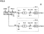
- Fig. 5 is a functional block diagram of a portion involved in controlling by the Fig. 1 MG-ECU 32 to charge.
- MG-ECU 32 includes a target value setting unit 70, a first control unit 72-1, and a second control unit 72-2.
- target value setting unit 70 When target value setting unit 70 receives command CHRG to charge and also receives electric power control value ⁇ P from battery ECU 30, target value setting unit 70 divides the received electric power control value ⁇ P by voltage Vb1 to generate a target current IR1, and divides electric power control value ⁇ P that is inverted in sign by voltage Vb2 to generate a target current IR2
- target value setting unit 70 receives command CHRG to charge and also receives charging electric power control values PB1, PB2 from battery ECU 30, target value setting unit 70 divides charging electric power control value PB1 by voltage Vb1 to generate target current IR1, and divides charging electric power control value PB2 by voltage Vb2 to generate target current IR2
- First control unit 72-1 includes subtraction units 74-1, 78-1, a PI control unit 76-1 and a modulation unit 80-1.
- Subtraction unit 74-1 subtracts current Ib1 from target current IR1 output from target value setting unit 70, and outputs the resultant calculation to PI control unit 76-1.
- PI control unit 76-1 performs a proportional-plus-integral operation with a deviation of target current IR1 and current Ib1 serving as an input, and outputs the resultant calculation to subtraction unit 78-1.
- Subtraction unit 78-1 subtracts the output of PI control unit 76-1 from an inverse of a theoretical upconversion ratio of converter 8-1 indicated by voltage Vb1/voltage VR (a target voltage for voltage Vh) and outputs the resultant calculation to modulation unit 80-1 as a duty command Ton1.
- Modulation unit 80-1 generates drive signal PWC1 based on duty command Ton1 and a carrier wave generated by an oscillation unit (not shown), and outputs the generated drive signal PWC1 to converter 8-1.
- Second control unit 72-2 includes subtraction units 74-2, 78-2, a PI control unit 76-2 and a modulation unit 80-2.
- Subtraction unit 74-2 subtracts current Ib2 from target current IR2 output from target value setting unit 70, and outputs the resultant calculation to PI control unit 76-2.
- PI control unit 76-2 performs a proportional-plus-integral operation with a deviation of target current IR2 and current Ib2 serving as an input, and outputs the resultant calculation to subtraction unit 78-2.
- Subtraction unit 78-2 subtracts the output of PI control unit 76-2 from an inverse of a theoretical upconversion ratio of converter 8-2 indicated by voltage Vb2/voltage VR and outputs the resultant calculation to modulation unit 80-2 as a duty command Ton2.
- Modulation unit 80-2 generates drive signal PWC2 based on duty command Ton2 and a carrier wave generated by an oscillation unit (not shown), and outputs the generated drive signal PWC2 to converter 8-2.
- converters 8-1, 8-2 are controlled to allow electric power storage devices 6-1 and 6-2 to charge/discharge therebetween before electric power storage devices 6-1, 6-2 are charged from external power supply 34.
- each electric power storage device's voltage and current are collected and therefrom the electric power storage device's voltage-current characteristic is calculated.
- the voltage-current characteristic can be calculated accurately.
- each electric power storage device's OCV is calculated, and from the calculated OCV, the electric power storage device's SOC is estimated.
- each electric power storage device's SOC can be estimated with high precision.
- charging/discharging each electric power storage device for calculating a current-voltage characteristic and an OCV to estimate an SOC is performed between electric power storage devices 6-1 and 6-2.
- an electric power loss is caused at converters 8-1, 8-2, electric power will never be wastefully discarded or consumed.
- the loss can be replenished by subsequently charging from external power supply 34.
- each electric power storage device 6-1, 6-2 is degraded is further determined from a voltage-current characteristic calculated in charging/discharging between electric power storage devices 6-1 and 6-2.
- the second embodiment provides an electric-powered vehicle generally identical in configuration to electric-powered vehicle 100 of the first embodiment shown in Fig. 1 .
- Fig. 6 is a functional block diagram of a battery ECU 30A in the second embodiment.
- battery ECU 30A corresponds in configuration to battery ECU 30 of the first embodiment, as shown in Fig. 2 , plus a degradation determination unit 62.
- Degradation determination unit 62 uses the voltage-current characteristics of electric power storage devices 6-1, 6-2 that are calculated by V-I characteristic calculation unit 50 in charging/discharging between electric power storage devices 6-1 and 6-2 to determine how electric power storage devices 6-1, 6-2 are degraded. More specifically, degradation determination unit 62 calculates dependency of voltage variation on current variation, i.e., an electric power storage device's internal resistance, as based on a current-voltage characteristic calculated by V-I characteristic calculation unit 50, and determines from the resultant calculation how each electric power storage device is degraded.
- Fig. 7 represents a voltage-current characteristic of an electric power storage device.
- a line k1 (k2) represents an identical electric power storage device's voltage-current characteristic, and as has been described previously, a voltage assumed for a current of zero indicates OCV.
- Line k1 (k2) has a slope, which indicates a magnitude of voltage variation relative to current variation, i.e., the electric power storage device's internal resistance.
- the current-voltage characteristic indicated by line k2 has a slope larger than that which the current-voltage characteristic indicated by line k1 has. In other words, it can be said that an electric power storage device having the current-voltage characteristic indicated by line k2 has larger internal resistance than that having the current-voltage characteristic indicated by line k1 and is thus more degraded.
- dependency (or a slope) of voltage variation relative to current variation is calculated in each electric power storage device's voltage-current characteristic calculated by V-I characteristic calculation unit 50 to determine how the electric power storage device is degraded.
- an accurate current-voltage characteristic calculated in charging/discharging between electric power storage devices 6-1 and 6-2 is used to determine whether they are degraded. Thus whether they are degraded can also be determined with high precision.
- Fig. 8 is a flowchart of a method of estimating the SOCs of electric power storage devices 6-1, 6-2 by battery ECU 30A in the second embodiment. With reference to Fig. 8 , this flowchart corresponds to the Fig. 4 flowchart plus steps S55, S57, S125.
- battery ECU 30A uses each electric power storage device's voltage-current characteristic that has been calculated in step S30 to determine how each electric power storage device is degraded (step S55). More specifically, battery ECU 30A calculates the slope of the voltage-current characteristic of each electric power storage device and compares the calculated slope with a preset threshold value to determine how each electric power storage device is degraded.
- step S55 if battery ECU 30A determines that at least one of electric power storage devices 6-1 and 6-2 has its voltage-current characteristic with a slope larger than the threshold value and is thus seriously degraded (NG in step S55), battery ECU 30A issues an alarm to the user (step S57). In contrast if in step S55 battery ECU 30A determines that each electric power storage device has its current-voltage characteristic with a slope of at most the threshold value and is thus not seriously degraded (OK in step S55), battery ECU 30A proceeds to step S60.
- battery ECU 30A uses each electric power storage device's voltage-current characteristic that has been calculated in step S100 to determine how each electric power storage device is degraded (step S125).
- step S125 battery ECU 30A determines that at least one of electric power storage devices 6-1, 6-2 is degraded (NG in step S125), battery ECU 30A proceeds to step S57. In contrast, if in step S125 battery ECU 30A determines that none of electric power storage devices 6-1, 6-2 is degraded (OK in step S125), battery ECU 30A proceeds to step S130.
- each electric power storage device's SOC can be estimated with high precision and how each electric power storage device is degraded can also be determined with high precision.
- Fig. 9 is a block diagram generally showing an electric-powered vehicle capable of receiving electric power from external power supply 34 through inverters 20-1, 20-2.
- electric-powered vehicle 100A corresponds in configuration to the Fig. 1 electric-powered vehicle 100 minus converter 26 for charging and plus electric power lines ACL1, ACL2.
- Electric power line ACL1 has one end connected to motor generator MG1 at a neutral point N1, and the other end connected to electric power receiving unit 28.
- Electric power line ACL2 has one end connected to motor generator MG2 at a neutral point N2, and the other end connected to electric power receiving unit 28.
- inverters 20-1, 20-2 When external power supply 34 charges electric power storage devices 6-1, 6-2, inverters 20-1, 20-2 receive AC power received from external power supply 34 through electric power lines ACL1, ACL2 by motor generators MG1, MG2 at neutral points N1, N2, convert the AC power to DC power in a method described later, and outputs the DC power on main positive bus MPL and main negative bus MNL
- Fig. 10 shows a zero phase equivalent circuit of inverters 20-1, 20-2 and motor generators MG1, MG2 shown in Fig. 9 .
- each inverter 20-1, 20-2 is formed of a 3-phase bridge circuit, and has six switching elements, which have on/off combinations in eight patterns. Of the eight switching patterns, two patterns allow an interphase voltage to be zero, and such a state of voltage is referred to as a zero voltage vector.
- upper arms' three switching elements can be regarded as being switched in mutually the same state (i.e., all on or off), and lower arms' three switching elements can also be regarded as being switched in mutually the same state. Accordingly in Fig.
- the three switching elements of the upper arms of inverter 20-1 are collectively shown as an upper arm 20-1A and the three switching elements of the lower arms of inverter 20-1 are collectively shown as a lower arm 20-1B.
- the three switching elements of the upper arms of inverter 20-2 are collectively shown as an upper arm 20-2A and the three switching elements of the lower arms of inverter 20-2 are collectively shown as a lower arm 20-2B.
- the zero phase equivalent circuit can be regarded as a single-phase PWM converter having an input of single phase AC power received at neutral points N1, N2 through electric power lines ACL1, ACL2. Accordingly, varying a zero voltage vector in each of inverters 20-1, 20-2 and controlling inverters 20-1, 20-2 to switch them to operate as arms of a single-phase PWM converter allow the AC power received from external power supply 34 through electric power lines ACL1, ACL2 to be converted to DC power and output on main positive and negative buses MPL and MNL
- electric-powered vehicle 100 (100A) has been described as including two electric power storage devices 6-1, 6-2 and converters 8-1, 8-2 corresponding thereto, respectively, it may alternatively include more electric power storage devices and converters corresponding thereto. In that case, charging/discharging between the plurality of electric power storage devices before charging them from external power supply 34 allows each electric power storage device's SOC to be estimated with high precision by the above described method.
- electric-powered vehicle 100 may be a hybrid vehicle having further mounted therein an internal combustion engine using fuel to generate kinetic energy, an electric vehicle that does not have an internal combustion engine mounted therein, a fuel cell vehicle having further mounted therein a fuel cell using fuel to generate electrical energy, or the like.
- the control exerted by battery ECU 30, 30A is in effect performed by a central processing unit (CPU).
- the CPU reads from a read only memory (ROM) a program including each step of the Figs. 4 and 8 flowcharts and executes the read program to perform a process in accordance with the Figs. 4 and 8 flowcharts.
- ROM read only memory
- the ROM corresponds to a computer (CPU) readable storage medium having each step of the Figs. 4 and 8 flowcharts stored therein.
- one of electric power storage devices 6-1, 6-2 corresponds to a "first electric power storage device” in the present invention.
- converters 8-1, 8-2 and electric power storage device 6-2 configure an “electric power device” in the present invention
- electric power storage device 6-2 corresponds to the "first electric power storage device”
- converters 8-1, 8-2 and electric power storage device 6-1 configure the "electric power device” in the present invention.
- converter 26 for charging corresponds to a "charging device” in the present invention
- inverters 20-1, 20-2, motor generators MG1, MG2 and electric power lines ACL1, ACL2 in electric-powered vehicle 100A also configure the "charging device” in the present invention
- battery ECU 30, 30A and MG-ECU 32 configure a "control device” in the present invention
- V-I characteristic calculation unit 50 corresponds to a "first operation unit” in the present invention.
- OCV calculation unit 52 corresponds to a "second operation unit” in the present invention
- initial SOC estimation unit 54 corresponds to a "state-of-charge estimation unit” in the present invention.
- electric power storage device 6-1 corresponds to the "first electric power storage device”
- electric power storage device 6-2 corresponds to “at least one second electric power storage device” in the present invention
- electric power storage device 6-1 corresponds to "at least one second electric power storage device” in the present invention
- converters 8-1, 8-2 correspond to "a plurality of voltage conversion devices” in the present invention.
Claims (11)
- Elektrisch betriebenes Fahrzeug mit:einer ersten elektrischen Speichervorrichtung (6-1), die in der Lage ist, geladen und entladen zu werden,einer Ladevorrichtung (26; 20-1, 20-2, MG1, MG2, ACL1, ACL2), die konfiguriert ist, in der Lage zu sein, die erste elektrische Speichervorrichtung (6-1) aus einer Leistungsversorgung (34), die außerhalb von dem Fahrzeug ist, zu laden,einer elektrischen Leistungsvorrichtung (8-1, 8-2, 6-2), die konfiguriert ist, in der Lage zu sein, elektrische Leistung mit der ersten elektrischen Speichervorrichtung (6-1) auszutauschen, undeiner Steuerungsvorrichtung (30, 32; 30A, 32) zur Steuerung der elektrischen Leistungsvorrichtung (8-1, 8-2, 6-2), wobei die Steuerungsvorrichtung (30, 32; 30A, 32) aufweist:eine Lade-/Entladesteuerungseinheit (56, 32), undeiner Ladezustandsschätzeinheit (54) zum Schätzen eines Ladezustands der ersten elektrischen Speichervorrichtung (6-1),dadurch gekennzeichnet, dass
die Lade-/Entladesteuerungseinheit (56, 32) konfiguriert ist, in Reaktion auf eine Anforderung zum Laden der ersten elektrischen Speichervorrichtung (6-1) durch die Ladevorrichtung (26; 20-1, 20-2, MG1, MG2, ACL1, ACL2) die elektrische Leistungsvorrichtung (8-1, 8-2, 6-2) derart zu steuern, dass der ersten elektrischen Speichervorrichtung (6-1) und der elektrischen Leistungsvorrichtung (8-1, 8-2, 6-2) erlaubt wird, elektrische Leistung dazwischen auszutauschen, bevor die erste elektrische Speichervorrichtung (6-1) durch die Ladevorrichtung (26; 20-1, 20-2, MG1, MG2, ACL1, ACL2) geladen wird,wobei die Steuerungsvorrichtung (30, 32; 30A, 32) weiterhin aufweist:eine erste Operationseinheit (50) zur Berechnung einer Spannungs-Strom-Charakteristik, die eine Korrelation zwischen einer Spannung und einem Strom der ersten elektrischen Speichervorrichtung (6-1) angibt, auf der Grundlage der Spannung und des Stroms, die an einer Vielzahl von Punkten gesammelt werden, während die erste elektrische Speichervorrichtung (6-1) und die elektrische Leistungsvorrichtung (8-1, 8-2, 6-2) elektrische Leistung miteinander austauschen, undeine zweite Betriebseinheit (52) zur Berechnung einer Leerlaufspannung der ersten elektrischen Speichervorrichtung (6-1) auf der Grundlage der durch die erste Operationseinheit (50) berechneten Spannungs-Strom-Charakteristik, wobeidie Ladezustandsschätzeinheit (54) konfiguriert ist, einen Ladezustand der ersten elektrischen Speichervorrichtung (6-1) anhand der durch die zweite Betriebseinheit (52) berechneten Leerlaufspannung unter Bezugnahme auf eine Korrelation, die zwischen einer Leerlaufspannung der ersten elektrischen Speichervorrichtung (6-1) und einem Ladezustand der der ersten elektrischen Speichervorrichtung (6-1) voreingestellt ist, zu schätzen. - Elektrisch betriebenes Fahrzeug nach Anspruch 1, wobei nach Schätzen des Ladezustands der ersten elektrischen Speichervorrichtung (6-1) durch die Ladezustandsschätzeinheit (54) die Ladevorrichtung (26; 20-1, 20-2, MG1, MG2, ACL1, ACL2) beginnt, die erste elektrische Speichervorrichtung (6-1) zu laden.
- Elektrisch betriebenes Fahrzeug nach Anspruch 1 oder 2, wobei
die elektrische Leistungsvorrichtung (8-1, 8-2, 6-2) zumindest eine zweite elektrische Leistungsspeichervorrichtung (6-2) aufweist, die in der Lage ist, geladen und entladen zu werden,
die erste Operationseinheit (50) weiterhin eine Spannungs-Strom-Charakteristik, die eine Korrelation zwischen einer Spannung und einem Strom der zumindest einen zweiten elektrischen Speichervorrichtung (6-2) angibt, auf der Grundlage einer Spannung und eines Stroms der zumindest einen zweiten elektrischen Speichervorrichtung (6-2) berechnet, die bereitgestellt werden, wenn die erste elektrischen Speichervorrichtung (6-1) und die zumindest eine zweite elektrische Speichervorrichtung (6-2) elektrische Leistung dazwischen austauschen,
die zweite Operationseinheit (52) weiterhin eine Leelaufspannung der zumindest einen zweiten elektrischen Speichervorrichtung (6-2) auf der Grundlage der durch die erste Operationseinheit (50) berechneten Spannungs-Strom-Charakteristik der zumindest einen zweiten elektrischen Speichervorrichtung (6-2) berechnet, und
die Ladezustandsschätzeinheit (54) weiterhin einen Ladezustand der zumindest einen zweiten elektrischen Speichervorrichtung (6-2) anhand der durch die zweite Betriebseinheit (52) berechneten Leerlaufspannung der zumindest einen zweiten elektrischen Speichervorrichtung (6-2) unter Bezugnahme auf eine Korrelation, die zwischen einer Leerlaufspannung und einem Ladezustand der zumindest einen zweiten elektrischen Speichervorrichtung (6-2) voreingestellt ist, schätzt. - Elektrisch betriebenes Fahrzeug nach Anspruch 3, wobei:die elektrische Leistungsvorrichtung (8-1, 8-2, 6-2) weiterhin eine Vielzahl von Leistungsumwandlungsvorrichtungen (8-1, 8-2) aufweist, die der ersten elektrischen Speichervorrichtung (6-1) und der zumindest einen zweiten elektrischen Speichervorrichtung (6-2) zugeordnet sind, unddie Lade-/Entladesteuerungseinheit (56, 32) die Vielzahl der Leistungsumwandlungsvorrichtungen (8-1, 8-2) steuert, um der ersten elektrischen Speichervorrichtung (6-1) und der zumindest einen zweiten elektrischen Speichervorrichtung (6-2) zu erlauben, elektrische Leistung dazwischen auszutauschen.
- Elektrisch betriebenes Fahrzeug nach Anspruch 1, wobei die Steuerungsvorrichtung (30A, 32) weiterhin eine Verschlechterungsbestimmungseinheit (62) zur Bestimmung, wie die erste elektrische Speichervorrichtung (6-1) verschlechtert ist, auf der Grundlage der durch die erste Operationseinheit (50) berechneten Spannungs-Strom-Charakteristik aufweist.
- Verfahren zum Schätzen eines Ladezustands einer elektrischen Leistungsspeichervorrichtung, die an einem elektrisch betriebenen Fahrzeug angebracht ist, wobei das elektrisch betriebene Fahrzeug aufweist:eine erste elektrische Speichervorrichtung (6-1), die in der Lage ist, geladen und entladen zu werden,eine Ladevorrichtung (26; 20-1, 20-2, MG1, MG2, ACL1, ACL2), die konfiguriert ist, in der Lage zu sein, die erste elektrische Speichervorrichtung (6-1) aus einer Leistungsversorgung (34), die außerhalb von dem Fahrzeug ist, zu laden,eine elektrische Leistungsvorrichtung (8-1, 8-2, 6-2), die konfiguriert ist, in der Lage zu sein, elektrische Leistung mit der ersten elektrischen Speichervorrichtung (6-1) auszutauschen, wobei das Verfahren gekennzeichnet ist durch:einen ersten Schritt des Steuerns der elektrischen Leistungsvorrichtung (8-1, 8-2, 6-2) derart, dass der ersten elektrischen Speichervorrichtung (6-1) und der elektrischen Leistungsvorrichtung (8-1, 8-2, 6-2) erlaubt wird, elektrische Leistung dazwischen auszutauschen, bevor die erste elektrische Speichervorrichtung (6-1) durch die Ladevorrichtung (26; 20-1, 20-2, MG1, MG2, ACL1, ACL2) geladen wird, in Reaktion auf eine Anforderung zum Laden der ersten elektrischen Speichervorrichtung (6-1) durch die Ladevorrichtung (26; 20-1, 20-2, MG1, MG2, ACL1, ACL2),einen zweiten Schritt des Berechnens einer Spannungs-Strom-Charakteristik, die eine Korrelation zwischen einer Spannung und einem Strom der ersten elektrischen Speichervorrichtung (6-1) angibt, auf der Grundlage der Spannung und des Stroms, die an einer Vielzahl von Punkten gesammelt werden, während die erste elektrische Speichervorrichtung (6-1) und die elektrische Leistungsvorrichtung (8-1, 8-2, 6-2) elektrische Leistung miteinander austauschen,einen dritten Schritt des Berechnens einer Leerlaufspannung der ersten elektrischen Speichervorrichtung (6-1) auf der Grundlage der berechneten Spannungs-Strom-Charakteristik, undeinen vierten Schritt des Schätzens des Ladezustands der ersten elektrischen Speichervorrichtung (6-1) anhand der in dem dritten Schritt berechneten Leerlaufspannung unter Bezugnahme auf eine Korrelation, die zwischen einer Leerlaufspannung und einem Ladezustand der der ersten elektrischen Speichervorrichtung (6-1) voreingestellt ist.
- Verfahren zum Schätzen eines Ladezustands nach Anspruch 6, weiterhin mit einem vierten Schritt des Beginnes des Ladens der ersten elektrischen Speichervorrichtung (6-1) durch die Ladevorrichtung (26; 20-1, 20-2, MG1, MG2, ACL1, ACL2) nach dem vierten Schritt des Schätzens des Ladezustands der ersten elektrischen Speichervorrichtung (6-1).
- Verfahren zum Schätzen eines Ladezustands nach Anspruch 6 oder 7, wobei
die elektrische Leistungsvorrichtung (8-1, 8-2, 6-2) zumindest eine zweite elektrische Leistungsspeichervorrichtung (6-2) aufweist, die in der Lage ist, geladen und entladen zu werden,
in dem zweiten Schritt weiterhin eine Spannungs-Strom-Charakteristik, die eine Korrelation zwischen einer Spannung und einem Strom der zumindest einen zweiten elektrischen Speichervorrichtung (6-2) angibt, auf der Grundlage einer Spannung und eines Stroms der zumindest einen zweiten elektrischen Speichervorrichtung (6-2) berechnet wird, die bereitgestellt werden, wenn die erste elektrischen Speichervorrichtung (6-1) und die zumindest eine zweite elektrische Speichervorrichtung (6-2) elektrische Leistung dazwischen austauschen,
in dem dritten Schritt eine Leelaufspannung der zumindest einen zweiten elektrischen Speichervorrichtung (6-2) auf der Grundlage der berechneten Spannungs-Strom-Charakteristik der zumindest einen zweiten elektrischen Speichervorrichtung (6-2) berechnet wird, und
in dem vierten Schritt weiterhin ein Ladezustand der zumindest einen zweiten elektrischen Speichervorrichtung (6-2) anhand der in dem dritten Schritt berechneten Leerlaufspannung der zumindest einen zweiten elektrischen Speichervorrichtung (6-2) unter Bezugnahme auf eine Korrelation, die zwischen einer Leerlaufspannung und einem Ladezustand der zumindest einen zweiten elektrischen Speichervorrichtung (6-2) voreingestellt ist, geschätzt wird. - Verfahren zum Schätzen eines Ladezustands nach Anspruch 8, wobei:die elektrische Leistungsvorrichtung (8-1, 8-2, 6-2) weiterhin eine Vielzahl von Leistungsumwandlungsvorrichtungen (8-1, 8-2) aufweist, die der ersten elektrischen Speichervorrichtung (6-1) und der zumindest einen zweiten elektrischen Speichervorrichtung (6-2) zugeordnet sind, undin dem ersten Schritt die Vielzahl der Leistungsumwandlungsvorrichtungen (8-1, 8-2) gesteuert werden, um der ersten elektrischen Speichervorrichtung (6-1) und der zumindest einen zweiten elektrischen Speichervorrichtung (6-2) zu erlauben, elektrische Leistung dazwischen auszutauschen.
- Verfahren zum Schätzen eines Ladezustands nach Anspruch 6, weiterhin mit einem sechsten Schritt des Bestimmens, wie die erste elektrische Speichervorrichtung (6-1) verschlechtert ist, auf der Grundlage der durch die erste Operationseinheit (50) berechneten Spannungs-Strom-Charakteristik.
- Computerlesbares Speichermedium mit einem darin gespeicherten Programm, um einen Computer zu veranlassen, das Verfahren zum Schätzen eines Ladezustands nach Anspruch 6 auszuführen.
Applications Claiming Priority (2)
| Application Number | Priority Date | Filing Date | Title |
|---|---|---|---|
| JP2007055795A JP4706648B2 (ja) | 2007-03-06 | 2007-03-06 | 電動車両、充電状態推定方法および充電状態推定方法をコンピュータに実行させるためのプログラムを記録したコンピュータ読取可能な記録媒体 |
| PCT/JP2008/054111 WO2008108455A1 (ja) | 2007-03-06 | 2008-02-29 | 電動車両、充電状態推定方法および充電状態推定方法をコンピュータに実行させるためのプログラムを記録したコンピュータ読取可能な記録媒体 |
Publications (3)
| Publication Number | Publication Date |
|---|---|
| EP2120309A1 EP2120309A1 (de) | 2009-11-18 |
| EP2120309A4 EP2120309A4 (de) | 2017-10-11 |
| EP2120309B1 true EP2120309B1 (de) | 2019-08-21 |
Family
ID=39738320
Family Applications (1)
| Application Number | Title | Priority Date | Filing Date |
|---|---|---|---|
| EP08721529.9A Active EP2120309B1 (de) | 2007-03-06 | 2008-02-29 | Elektrofahrzeug, verfahren zur kalkulation des ladezustandes sowie computerlesbares aufzeichnungsmedium mit aufzeichnung eines programmes für die ausführung der ladestandskalkulation auf einem computer |
Country Status (9)
| Country | Link |
|---|---|
| US (1) | US8648571B2 (de) |
| EP (1) | EP2120309B1 (de) |
| JP (1) | JP4706648B2 (de) |
| KR (1) | KR101087632B1 (de) |
| CN (1) | CN101627517B (de) |
| BR (1) | BRPI0808425B1 (de) |
| ES (1) | ES2746476T3 (de) |
| RU (1) | RU2416142C1 (de) |
| WO (1) | WO2008108455A1 (de) |
Families Citing this family (38)
| Publication number | Priority date | Publication date | Assignee | Title |
|---|---|---|---|---|
| JP4893653B2 (ja) * | 2008-02-19 | 2012-03-07 | トヨタ自動車株式会社 | 車両、二次電池の充電状態推定方法および車両の制御方法 |
| JP5187152B2 (ja) * | 2008-11-17 | 2013-04-24 | トヨタ自動車株式会社 | 車両の電源システムおよび車両 |
| JP5301657B2 (ja) * | 2009-03-27 | 2013-09-25 | 株式会社日立製作所 | 蓄電装置 |
| JP4978662B2 (ja) | 2009-06-24 | 2012-07-18 | トヨタ自動車株式会社 | 充電状態推定装置および充電状態推定方法 |
| WO2011105083A1 (ja) * | 2010-02-25 | 2011-09-01 | 三洋電機株式会社 | バッテリ制御装置、バッテリシステム、電動車両、充電制御装置、充電器、移動体、電源システム、電力貯蔵装置および電源装置 |
| US8820444B2 (en) * | 2010-04-16 | 2014-09-02 | Tuan Nguyen | Electric vehicle having exchangeable battery modules and method of resupply therefor |
| WO2011155017A1 (ja) * | 2010-06-07 | 2011-12-15 | 三菱電機株式会社 | 充電状態推定装置 |
| US9726732B2 (en) * | 2010-06-22 | 2017-08-08 | GM Global Technology Operations LLC | Adaptive battery parameter extraction and SOC estimation for lithium-ion battery |
| US9354277B2 (en) * | 2010-10-29 | 2016-05-31 | Gm Global Technology Operatins Llc | Apparatus of SOC estimation during plug-in charge mode |
| KR101238478B1 (ko) * | 2011-01-16 | 2013-03-04 | 김득수 | 배터리 잔존 용량 측정 방법 |
| JP5747610B2 (ja) * | 2011-03-30 | 2015-07-15 | ソニー株式会社 | 充電制御装置、充電制御方法、プログラム及びシステム |
| JP5794525B2 (ja) * | 2011-07-22 | 2015-10-14 | 東洋電産株式会社 | 電気自動車用バッテリー充電装置およびレスキュー車 |
| JP5870590B2 (ja) * | 2011-09-29 | 2016-03-01 | ミツミ電機株式会社 | 電池状態計測方法及び電池状態計測装置 |
| JP5857229B2 (ja) * | 2011-09-30 | 2016-02-10 | パナソニックIpマネジメント株式会社 | 内部抵抗検出回路、及び電池電源装置 |
| JP6065561B2 (ja) * | 2012-03-08 | 2017-01-25 | 日産自動車株式会社 | 二次電池の制御装置およびsoc検出方法 |
| FR2989779B1 (fr) * | 2012-04-19 | 2015-02-06 | Commissariat Energie Atomique | Dispositif de determination d'une caracteristique d'une batterie et procede de fonctionnement d'un tel dispositif |
| KR101394867B1 (ko) | 2012-09-28 | 2014-05-13 | 기아자동차주식회사 | 친환경 차량의 주행가능거리 산출 방법 |
| US20140320085A1 (en) * | 2013-04-24 | 2014-10-30 | Dynapack International Technology Corporation | Charging device and control method thereof |
| US9205750B2 (en) | 2013-07-23 | 2015-12-08 | Ford Global Technologies, Llc | Method to estimate battery open-circuit voltage based on transient resistive effects |
| JP6260812B2 (ja) * | 2013-12-05 | 2018-01-17 | パナソニックIpマネジメント株式会社 | 電池残存容量推定装置、電池残存容量判定方法及び電池残存容量判定プログラム |
| CN104714182A (zh) * | 2013-12-11 | 2015-06-17 | 广州汽车集团股份有限公司 | 一种确定电池荷电状态值的方法和系统 |
| GB201407805D0 (en) | 2014-05-02 | 2014-06-18 | Dukosi Ltd | Battery condition determination |
| US20160001670A1 (en) * | 2014-07-01 | 2016-01-07 | Ford Global Technologies, Llc | System and method for battery management |
| JP6412847B2 (ja) | 2015-10-27 | 2018-10-24 | 本田技研工業株式会社 | 蓄電装置及び制御方法 |
| JP6364396B2 (ja) * | 2015-10-27 | 2018-07-25 | 本田技研工業株式会社 | 蓄電装置、輸送機器及び制御方法 |
| JP6220904B2 (ja) | 2016-01-14 | 2017-10-25 | 本田技研工業株式会社 | 蓄電装置 |
| JP5948518B1 (ja) * | 2016-02-04 | 2016-07-06 | 本田技研工業株式会社 | 蓄電装置、該蓄電装置を有する輸送機器、故障判断方法、および故障判断プログラム |
| JP6122164B1 (ja) * | 2016-02-04 | 2017-04-26 | 本田技研工業株式会社 | 蓄電装置、該蓄電装置を有する輸送機器、蓄電池のsocとocvの相関情報を確定する確定方法、および該相関情報を確定するプログラム |
| JP5980459B1 (ja) | 2016-03-30 | 2016-08-31 | 本田技研工業株式会社 | 電源装置、該電源装置を有する輸送機器、蓄電部の充電率と開放端電圧の相関情報を推定する推定方法、および該相関情報を推定するためのプログラム |
| JP5980458B1 (ja) * | 2016-03-30 | 2016-08-31 | 本田技研工業株式会社 | 電源装置、該電源装置を有する輸送機器、蓄電部の充電率と開放端電圧の相関情報を推定する推定方法、および該相関情報を推定するためのプログラム |
| JP5980457B1 (ja) | 2016-03-30 | 2016-08-31 | 本田技研工業株式会社 | 電源装置、該電源装置を有する輸送機器、蓄電部の充電率と開放端電圧の相関情報を推定する推定方法、および該相関情報を推定するためのプログラム |
| CN107340476B (zh) * | 2016-04-29 | 2021-01-26 | 株式会社日立制作所 | 电池的电气状态监测系统和电气状态监测方法 |
| JP6551362B2 (ja) * | 2016-10-20 | 2019-07-31 | 株式会社デンソー | 電源システム |
| CN106427652B (zh) * | 2016-11-23 | 2018-08-21 | 杭州衡源汽车科技有限公司 | 电动车的充电切换系统及其控制方法 |
| CN107359379B (zh) * | 2017-07-19 | 2019-11-26 | 华霆(合肥)动力技术有限公司 | 快速充电方法及装置 |
| CN109606202B (zh) * | 2019-01-07 | 2024-01-26 | 郑州轻工业学院 | 动力电池控制方法及装置 |
| CN113634645B (zh) * | 2021-08-27 | 2023-05-02 | 保隆(安徽)汽车配件有限公司 | 一种防止产品变形的翻边模具和翻边方法 |
| DE102022209368A1 (de) * | 2022-09-08 | 2024-03-14 | Siemens Mobility GmbH | Verfahren zum Bestimmen einer Spannungskennlinie eines elektrischen Energiespeichers |
Citations (1)
| Publication number | Priority date | Publication date | Assignee | Title |
|---|---|---|---|---|
| JP2000306613A (ja) * | 1999-04-20 | 2000-11-02 | Nissan Motor Co Ltd | バッテリ状態監視装置 |
Family Cites Families (16)
| Publication number | Priority date | Publication date | Assignee | Title |
|---|---|---|---|---|
| JP3864590B2 (ja) | 1998-11-25 | 2007-01-10 | トヨタ自動車株式会社 | バッテリ充電状態検出装置 |
| JP3543662B2 (ja) | 1999-03-09 | 2004-07-14 | 日産自動車株式会社 | 電気自動車用二次電池のsoc演算方法 |
| JP3706565B2 (ja) * | 2001-09-20 | 2005-10-12 | 三洋電機株式会社 | ハイブリッドカー用の電源装置 |
| JP4048766B2 (ja) * | 2001-12-11 | 2008-02-20 | トヨタ車体株式会社 | ハイブリッド車両 |
| JP2004354050A (ja) | 2002-05-14 | 2004-12-16 | Yazaki Corp | バッテリの充電状態推定方法及び開回路電圧推定方法、並びに、劣化度算出方法及び装置 |
| JP2004031123A (ja) * | 2002-06-26 | 2004-01-29 | Nissan Motor Co Ltd | 並列接続された組電池の容量演算方法および装置 |
| JP4228760B2 (ja) * | 2002-07-12 | 2009-02-25 | トヨタ自動車株式会社 | バッテリ充電状態推定装置 |
| JP3689084B2 (ja) * | 2002-12-11 | 2005-08-31 | 三菱電機株式会社 | バッテリ充電状態演算装置およびバッテリ充電状態演算方法 |
| US7323848B2 (en) * | 2002-12-11 | 2008-01-29 | Japan Storage Battery Co., Ltd. | Battery charging state arithmetic operation device for calculating charging state of battery, and battery charging state arithmetic operation method |
| JP2005147987A (ja) * | 2003-11-19 | 2005-06-09 | Yazaki Corp | 飽和分極推定方法及び装置、並びに、放電可能容量推定方法 |
| RU2282301C2 (ru) | 2004-10-11 | 2006-08-20 | Государственное образовательное учреждение высшего профессионального образования Самарский государственный технический университет | Энергетическая установка с асинхронным стартер-генератором |
| JP4085334B2 (ja) * | 2004-11-09 | 2008-05-14 | 株式会社デンソー | 二電源型車両用電源装置 |
| CN100364203C (zh) | 2005-01-21 | 2008-01-23 | 宇泉能源科技股份有限公司 | 可携式复合型电池管理系统 |
| JP4520959B2 (ja) * | 2005-04-22 | 2010-08-11 | アイシン精機株式会社 | 電力供給システム |
| JP4839722B2 (ja) * | 2005-08-08 | 2011-12-21 | トヨタ自動車株式会社 | 車両の電源装置 |
| CA2523240C (en) * | 2005-10-11 | 2009-12-08 | Delaware Systems Inc. | Universal battery module and controller therefor |
-
2007
- 2007-03-06 JP JP2007055795A patent/JP4706648B2/ja active Active
-
2008
- 2008-02-29 RU RU2009136696/07A patent/RU2416142C1/ru not_active IP Right Cessation
- 2008-02-29 US US12/449,035 patent/US8648571B2/en not_active Expired - Fee Related
- 2008-02-29 KR KR1020097020742A patent/KR101087632B1/ko not_active IP Right Cessation
- 2008-02-29 ES ES08721529T patent/ES2746476T3/es active Active
- 2008-02-29 WO PCT/JP2008/054111 patent/WO2008108455A1/ja active Application Filing
- 2008-02-29 BR BRPI0808425-4A patent/BRPI0808425B1/pt not_active IP Right Cessation
- 2008-02-29 EP EP08721529.9A patent/EP2120309B1/de active Active
- 2008-02-29 CN CN2008800070079A patent/CN101627517B/zh not_active Expired - Fee Related
Patent Citations (1)
| Publication number | Priority date | Publication date | Assignee | Title |
|---|---|---|---|---|
| JP2000306613A (ja) * | 1999-04-20 | 2000-11-02 | Nissan Motor Co Ltd | バッテリ状態監視装置 |
Also Published As
| Publication number | Publication date |
|---|---|
| KR101087632B1 (ko) | 2011-11-30 |
| EP2120309A1 (de) | 2009-11-18 |
| CN101627517B (zh) | 2013-01-09 |
| CN101627517A (zh) | 2010-01-13 |
| BRPI0808425A2 (pt) | 2014-07-22 |
| EP2120309A4 (de) | 2017-10-11 |
| BRPI0808425B1 (pt) | 2019-04-24 |
| JP2008220080A (ja) | 2008-09-18 |
| WO2008108455A1 (ja) | 2008-09-12 |
| US20100045239A1 (en) | 2010-02-25 |
| ES2746476T3 (es) | 2020-03-06 |
| RU2416142C1 (ru) | 2011-04-10 |
| US8648571B2 (en) | 2014-02-11 |
| KR20090117835A (ko) | 2009-11-12 |
| JP4706648B2 (ja) | 2011-06-22 |
Similar Documents
| Publication | Publication Date | Title |
|---|---|---|
| EP2120309B1 (de) | Elektrofahrzeug, verfahren zur kalkulation des ladezustandes sowie computerlesbares aufzeichnungsmedium mit aufzeichnung eines programmes für die ausführung der ladestandskalkulation auf einem computer | |
| JP4893653B2 (ja) | 車両、二次電池の充電状態推定方法および車両の制御方法 | |
| EP2472700B1 (de) | Ladesteuerungsvorrichtung für ein fahrzeug und damit ausgestattetes elektrofahrzeug | |
| EP2080661B1 (de) | Elektrofahrzeug und verfahren zur steuerung der spannungsumwandlungsvorrichtung | |
| US8912761B2 (en) | Upper-limit of state-of-charge estimating device and upper-limit of state-of-charge estimating method | |
| EP2159099B1 (de) | Stromversorgungsvorrichtung für ein fahrzeug, verfahren zur schätzung des ladestatus eines akkumulators in der stromversorgungsvorrichtung an bord des fahrzeugs | |
| JP5407758B2 (ja) | 車両の電源装置 | |
| JP5413507B2 (ja) | 車両用制御装置および車両用制御方法 | |
| WO2010089889A1 (ja) | 電源システムおよびそれを備えた電動車両 | |
| WO2012176275A1 (ja) | 蓄電装置用の充電装置およびそれを搭載する車両 | |
| WO2008044516A1 (fr) | Véhicule hybride, procédé de commande de véhicule hybride, programme pour amener un ordinateur à exécuter le procédé de commande, et support d'enregistrement lisible par un ordinateur contenant le programme | |
| US11750006B2 (en) | Estimation system and estimation method |
Legal Events
| Date | Code | Title | Description |
|---|---|---|---|
| PUAI | Public reference made under article 153(3) epc to a published international application that has entered the european phase |
Free format text: ORIGINAL CODE: 0009012 |
|
| 17P | Request for examination filed |
Effective date: 20090729 |
|
| AK | Designated contracting states |
Kind code of ref document: A1 Designated state(s): AT BE BG CH CY CZ DE DK EE ES FI FR GB GR HR HU IE IS IT LI LT LU LV MC MT NL NO PL PT RO SE SI SK TR |
|
| DAX | Request for extension of the european patent (deleted) | ||
| RAP1 | Party data changed (applicant data changed or rights of an application transferred) |
Owner name: TOYOTA JIDOSHA KABUSHIKI KAISHA |
|
| RA4 | Supplementary search report drawn up and despatched (corrected) |
Effective date: 20170907 |
|
| RIC1 | Information provided on ipc code assigned before grant |
Ipc: H01M 10/48 20060101ALI20170901BHEP Ipc: G01R 31/36 20060101ALI20170901BHEP Ipc: B60L 11/18 20060101ALI20170901BHEP Ipc: H02J 7/00 20060101AFI20170901BHEP Ipc: H01M 10/44 20060101ALI20170901BHEP Ipc: B60L 3/00 20060101ALI20170901BHEP Ipc: B60R 16/04 20060101ALI20170901BHEP |
|
| STAA | Information on the status of an ep patent application or granted ep patent |
Free format text: STATUS: EXAMINATION IS IN PROGRESS |
|
| 17Q | First examination report despatched |
Effective date: 20180907 |
|
| REG | Reference to a national code |
Ref country code: DE Ref legal event code: R079 Ref document number: 602008060968 Country of ref document: DE Free format text: PREVIOUS MAIN CLASS: H02J0007000000 Ipc: B60L0003000000 |
|
| GRAP | Despatch of communication of intention to grant a patent |
Free format text: ORIGINAL CODE: EPIDOSNIGR1 |
|
| STAA | Information on the status of an ep patent application or granted ep patent |
Free format text: STATUS: GRANT OF PATENT IS INTENDED |
|
| RIC1 | Information provided on ipc code assigned before grant |
Ipc: H01M 10/44 20060101ALI20190321BHEP Ipc: B60L 3/00 20190101AFI20190321BHEP Ipc: B60L 53/00 20190101ALI20190321BHEP Ipc: B60R 16/04 20060101ALI20190321BHEP Ipc: H02J 7/00 20060101ALI20190321BHEP Ipc: B60L 58/20 20190101ALI20190321BHEP Ipc: G01R 31/36 20190101ALI20190321BHEP Ipc: H01M 10/48 20060101ALI20190321BHEP |
|
| INTG | Intention to grant announced |
Effective date: 20190410 |
|
| GRAS | Grant fee paid |
Free format text: ORIGINAL CODE: EPIDOSNIGR3 |
|
| GRAA | (expected) grant |
Free format text: ORIGINAL CODE: 0009210 |
|
| STAA | Information on the status of an ep patent application or granted ep patent |
Free format text: STATUS: THE PATENT HAS BEEN GRANTED |
|
| AK | Designated contracting states |
Kind code of ref document: B1 Designated state(s): AT BE BG CH CY CZ DE DK EE ES FI FR GB GR HR HU IE IS IT LI LT LU LV MC MT NL NO PL PT RO SE SI SK TR |
|
| REG | Reference to a national code |
Ref country code: GB Ref legal event code: FG4D |
|
| REG | Reference to a national code |
Ref country code: CH Ref legal event code: EP |
|
| REG | Reference to a national code |
Ref country code: DE Ref legal event code: R096 Ref document number: 602008060968 Country of ref document: DE |
|
| REG | Reference to a national code |
Ref country code: AT Ref legal event code: REF Ref document number: 1169337 Country of ref document: AT Kind code of ref document: T Effective date: 20190915 |
|
| REG | Reference to a national code |
Ref country code: IE Ref legal event code: FG4D |
|
| REG | Reference to a national code |
Ref country code: DE Ref legal event code: R084 Ref document number: 602008060968 Country of ref document: DE |
|
| REG | Reference to a national code |
Ref country code: GB Ref legal event code: 746 Effective date: 20190924 |
|
| REG | Reference to a national code |
Ref country code: LT Ref legal event code: MG4D |
|
| REG | Reference to a national code |
Ref country code: NL Ref legal event code: MP Effective date: 20190821 |
|
| PG25 | Lapsed in a contracting state [announced via postgrant information from national office to epo] |
Ref country code: PT Free format text: LAPSE BECAUSE OF FAILURE TO SUBMIT A TRANSLATION OF THE DESCRIPTION OR TO PAY THE FEE WITHIN THE PRESCRIBED TIME-LIMIT Effective date: 20191223 Ref country code: NO Free format text: LAPSE BECAUSE OF FAILURE TO SUBMIT A TRANSLATION OF THE DESCRIPTION OR TO PAY THE FEE WITHIN THE PRESCRIBED TIME-LIMIT Effective date: 20191121 Ref country code: SE Free format text: LAPSE BECAUSE OF FAILURE TO SUBMIT A TRANSLATION OF THE DESCRIPTION OR TO PAY THE FEE WITHIN THE PRESCRIBED TIME-LIMIT Effective date: 20190821 Ref country code: FI Free format text: LAPSE BECAUSE OF FAILURE TO SUBMIT A TRANSLATION OF THE DESCRIPTION OR TO PAY THE FEE WITHIN THE PRESCRIBED TIME-LIMIT Effective date: 20190821 Ref country code: LT Free format text: LAPSE BECAUSE OF FAILURE TO SUBMIT A TRANSLATION OF THE DESCRIPTION OR TO PAY THE FEE WITHIN THE PRESCRIBED TIME-LIMIT Effective date: 20190821 Ref country code: HR Free format text: LAPSE BECAUSE OF FAILURE TO SUBMIT A TRANSLATION OF THE DESCRIPTION OR TO PAY THE FEE WITHIN THE PRESCRIBED TIME-LIMIT Effective date: 20190821 Ref country code: BG Free format text: LAPSE BECAUSE OF FAILURE TO SUBMIT A TRANSLATION OF THE DESCRIPTION OR TO PAY THE FEE WITHIN THE PRESCRIBED TIME-LIMIT Effective date: 20191121 Ref country code: NL Free format text: LAPSE BECAUSE OF FAILURE TO SUBMIT A TRANSLATION OF THE DESCRIPTION OR TO PAY THE FEE WITHIN THE PRESCRIBED TIME-LIMIT Effective date: 20190821 |
|
| PG25 | Lapsed in a contracting state [announced via postgrant information from national office to epo] |
Ref country code: LV Free format text: LAPSE BECAUSE OF FAILURE TO SUBMIT A TRANSLATION OF THE DESCRIPTION OR TO PAY THE FEE WITHIN THE PRESCRIBED TIME-LIMIT Effective date: 20190821 Ref country code: IS Free format text: LAPSE BECAUSE OF FAILURE TO SUBMIT A TRANSLATION OF THE DESCRIPTION OR TO PAY THE FEE WITHIN THE PRESCRIBED TIME-LIMIT Effective date: 20191221 Ref country code: GR Free format text: LAPSE BECAUSE OF FAILURE TO SUBMIT A TRANSLATION OF THE DESCRIPTION OR TO PAY THE FEE WITHIN THE PRESCRIBED TIME-LIMIT Effective date: 20191122 |
|
| REG | Reference to a national code |
Ref country code: ES Ref legal event code: FG2A Ref document number: 2746476 Country of ref document: ES Kind code of ref document: T3 Effective date: 20200306 |
|
| REG | Reference to a national code |
Ref country code: AT Ref legal event code: MK05 Ref document number: 1169337 Country of ref document: AT Kind code of ref document: T Effective date: 20190821 |
|
| PG25 | Lapsed in a contracting state [announced via postgrant information from national office to epo] |
Ref country code: TR Free format text: LAPSE BECAUSE OF FAILURE TO SUBMIT A TRANSLATION OF THE DESCRIPTION OR TO PAY THE FEE WITHIN THE PRESCRIBED TIME-LIMIT Effective date: 20190821 |
|
| PG25 | Lapsed in a contracting state [announced via postgrant information from national office to epo] |
Ref country code: RO Free format text: LAPSE BECAUSE OF FAILURE TO SUBMIT A TRANSLATION OF THE DESCRIPTION OR TO PAY THE FEE WITHIN THE PRESCRIBED TIME-LIMIT Effective date: 20190821 Ref country code: PL Free format text: LAPSE BECAUSE OF FAILURE TO SUBMIT A TRANSLATION OF THE DESCRIPTION OR TO PAY THE FEE WITHIN THE PRESCRIBED TIME-LIMIT Effective date: 20190821 Ref country code: AT Free format text: LAPSE BECAUSE OF FAILURE TO SUBMIT A TRANSLATION OF THE DESCRIPTION OR TO PAY THE FEE WITHIN THE PRESCRIBED TIME-LIMIT Effective date: 20190821 Ref country code: DK Free format text: LAPSE BECAUSE OF FAILURE TO SUBMIT A TRANSLATION OF THE DESCRIPTION OR TO PAY THE FEE WITHIN THE PRESCRIBED TIME-LIMIT Effective date: 20190821 Ref country code: EE Free format text: LAPSE BECAUSE OF FAILURE TO SUBMIT A TRANSLATION OF THE DESCRIPTION OR TO PAY THE FEE WITHIN THE PRESCRIBED TIME-LIMIT Effective date: 20190821 |
|
| PG25 | Lapsed in a contracting state [announced via postgrant information from national office to epo] |
Ref country code: CZ Free format text: LAPSE BECAUSE OF FAILURE TO SUBMIT A TRANSLATION OF THE DESCRIPTION OR TO PAY THE FEE WITHIN THE PRESCRIBED TIME-LIMIT Effective date: 20190821 Ref country code: SK Free format text: LAPSE BECAUSE OF FAILURE TO SUBMIT A TRANSLATION OF THE DESCRIPTION OR TO PAY THE FEE WITHIN THE PRESCRIBED TIME-LIMIT Effective date: 20190821 Ref country code: IS Free format text: LAPSE BECAUSE OF FAILURE TO SUBMIT A TRANSLATION OF THE DESCRIPTION OR TO PAY THE FEE WITHIN THE PRESCRIBED TIME-LIMIT Effective date: 20200224 |
|
| REG | Reference to a national code |
Ref country code: DE Ref legal event code: R097 Ref document number: 602008060968 Country of ref document: DE |
|
| PLBE | No opposition filed within time limit |
Free format text: ORIGINAL CODE: 0009261 |
|
| STAA | Information on the status of an ep patent application or granted ep patent |
Free format text: STATUS: NO OPPOSITION FILED WITHIN TIME LIMIT |
|
| PG2D | Information on lapse in contracting state deleted |
Ref country code: IS |
|
| 26N | No opposition filed |
Effective date: 20200603 |
|
| PG25 | Lapsed in a contracting state [announced via postgrant information from national office to epo] |
Ref country code: SI Free format text: LAPSE BECAUSE OF FAILURE TO SUBMIT A TRANSLATION OF THE DESCRIPTION OR TO PAY THE FEE WITHIN THE PRESCRIBED TIME-LIMIT Effective date: 20190821 |
|
| REG | Reference to a national code |
Ref country code: CH Ref legal event code: PL |
|
| REG | Reference to a national code |
Ref country code: BE Ref legal event code: MM Effective date: 20200229 |
|
| PG25 | Lapsed in a contracting state [announced via postgrant information from national office to epo] |
Ref country code: LU Free format text: LAPSE BECAUSE OF NON-PAYMENT OF DUE FEES Effective date: 20200229 Ref country code: MC Free format text: LAPSE BECAUSE OF FAILURE TO SUBMIT A TRANSLATION OF THE DESCRIPTION OR TO PAY THE FEE WITHIN THE PRESCRIBED TIME-LIMIT Effective date: 20190821 |
|
| PG25 | Lapsed in a contracting state [announced via postgrant information from national office to epo] |
Ref country code: LI Free format text: LAPSE BECAUSE OF NON-PAYMENT OF DUE FEES Effective date: 20200229 Ref country code: CH Free format text: LAPSE BECAUSE OF NON-PAYMENT OF DUE FEES Effective date: 20200229 |
|
| PG25 | Lapsed in a contracting state [announced via postgrant information from national office to epo] |
Ref country code: IE Free format text: LAPSE BECAUSE OF NON-PAYMENT OF DUE FEES Effective date: 20200229 |
|
| PG25 | Lapsed in a contracting state [announced via postgrant information from national office to epo] |
Ref country code: BE Free format text: LAPSE BECAUSE OF NON-PAYMENT OF DUE FEES Effective date: 20200229 |
|
| PGFP | Annual fee paid to national office [announced via postgrant information from national office to epo] |
Ref country code: IT Payment date: 20210112 Year of fee payment: 14 Ref country code: FR Payment date: 20210113 Year of fee payment: 14 |
|
| PGFP | Annual fee paid to national office [announced via postgrant information from national office to epo] |
Ref country code: DE Payment date: 20210216 Year of fee payment: 14 Ref country code: ES Payment date: 20210308 Year of fee payment: 14 Ref country code: GB Payment date: 20210219 Year of fee payment: 14 |
|
| PG25 | Lapsed in a contracting state [announced via postgrant information from national office to epo] |
Ref country code: MT Free format text: LAPSE BECAUSE OF FAILURE TO SUBMIT A TRANSLATION OF THE DESCRIPTION OR TO PAY THE FEE WITHIN THE PRESCRIBED TIME-LIMIT Effective date: 20190821 Ref country code: CY Free format text: LAPSE BECAUSE OF FAILURE TO SUBMIT A TRANSLATION OF THE DESCRIPTION OR TO PAY THE FEE WITHIN THE PRESCRIBED TIME-LIMIT Effective date: 20190821 |
|
| REG | Reference to a national code |
Ref country code: DE Ref legal event code: R119 Ref document number: 602008060968 Country of ref document: DE |
|
| GBPC | Gb: european patent ceased through non-payment of renewal fee |
Effective date: 20220228 |
|
| PG25 | Lapsed in a contracting state [announced via postgrant information from national office to epo] |
Ref country code: FR Free format text: LAPSE BECAUSE OF NON-PAYMENT OF DUE FEES Effective date: 20220228 |
|
| PG25 | Lapsed in a contracting state [announced via postgrant information from national office to epo] |
Ref country code: GB Free format text: LAPSE BECAUSE OF NON-PAYMENT OF DUE FEES Effective date: 20220228 Ref country code: DE Free format text: LAPSE BECAUSE OF NON-PAYMENT OF DUE FEES Effective date: 20220901 |
|
| REG | Reference to a national code |
Ref country code: ES Ref legal event code: FD2A Effective date: 20230404 |
|
| PG25 | Lapsed in a contracting state [announced via postgrant information from national office to epo] |
Ref country code: ES Free format text: LAPSE BECAUSE OF NON-PAYMENT OF DUE FEES Effective date: 20220301 |
|
| PG25 | Lapsed in a contracting state [announced via postgrant information from national office to epo] |
Ref country code: IT Free format text: LAPSE BECAUSE OF NON-PAYMENT OF DUE FEES Effective date: 20220301 |