EP2120058A2 - Ortung einer Störung mit niedrigem Widerstand in einem elektrischen Kabel - Google Patents
Ortung einer Störung mit niedrigem Widerstand in einem elektrischen Kabel Download PDFInfo
- Publication number
- EP2120058A2 EP2120058A2 EP09159922A EP09159922A EP2120058A2 EP 2120058 A2 EP2120058 A2 EP 2120058A2 EP 09159922 A EP09159922 A EP 09159922A EP 09159922 A EP09159922 A EP 09159922A EP 2120058 A2 EP2120058 A2 EP 2120058A2
- Authority
- EP
- European Patent Office
- Prior art keywords
- cable
- oscillator
- fault
- resistance
- inductance
- Prior art date
- Legal status (The legal status is an assumption and is not a legal conclusion. Google has not performed a legal analysis and makes no representation as to the accuracy of the status listed.)
- Withdrawn
Links
- 230000010355 oscillation Effects 0.000 claims abstract description 86
- 238000012360 testing method Methods 0.000 claims abstract description 66
- 238000005259 measurement Methods 0.000 claims abstract description 49
- 238000000034 method Methods 0.000 claims abstract description 37
- 230000008878 coupling Effects 0.000 claims description 9
- 238000010168 coupling process Methods 0.000 claims description 9
- 238000005859 coupling reaction Methods 0.000 claims description 9
- 230000035945 sensitivity Effects 0.000 claims description 8
- 230000001939 inductive effect Effects 0.000 claims description 5
- 238000012545 processing Methods 0.000 claims description 5
- 230000001419 dependent effect Effects 0.000 claims description 4
- 238000006243 chemical reaction Methods 0.000 abstract description 2
- 238000004519 manufacturing process Methods 0.000 abstract description 2
- 230000007613 environmental effect Effects 0.000 abstract 1
- 230000008901 benefit Effects 0.000 description 7
- 238000010586 diagram Methods 0.000 description 7
- 239000004020 conductor Substances 0.000 description 4
- 230000002238 attenuated effect Effects 0.000 description 3
- 230000000694 effects Effects 0.000 description 3
- 238000010276 construction Methods 0.000 description 2
- 238000002310 reflectometry Methods 0.000 description 2
- 230000008929 regeneration Effects 0.000 description 2
- 238000011069 regeneration method Methods 0.000 description 2
- 230000036962 time dependent Effects 0.000 description 2
- 238000012549 training Methods 0.000 description 2
- 238000012935 Averaging Methods 0.000 description 1
- 230000032683 aging Effects 0.000 description 1
- 239000003990 capacitor Substances 0.000 description 1
- 238000004891 communication Methods 0.000 description 1
- 238000013480 data collection Methods 0.000 description 1
- 230000001934 delay Effects 0.000 description 1
- 238000001514 detection method Methods 0.000 description 1
- 230000005611 electricity Effects 0.000 description 1
- 238000002474 experimental method Methods 0.000 description 1
- 238000001453 impedance spectrum Methods 0.000 description 1
- 238000012986 modification Methods 0.000 description 1
- 230000004048 modification Effects 0.000 description 1
- 230000000737 periodic effect Effects 0.000 description 1
- 230000008569 process Effects 0.000 description 1
- 230000000135 prohibitive effect Effects 0.000 description 1
- 229920006395 saturated elastomer Polymers 0.000 description 1
- 238000001228 spectrum Methods 0.000 description 1
- 230000009897 systematic effect Effects 0.000 description 1
Images


Classifications
-
- G—PHYSICS
- G01—MEASURING; TESTING
- G01R—MEASURING ELECTRIC VARIABLES; MEASURING MAGNETIC VARIABLES
- G01R31/00—Arrangements for testing electric properties; Arrangements for locating electric faults; Arrangements for electrical testing characterised by what is being tested not provided for elsewhere
- G01R31/08—Locating faults in cables, transmission lines, or networks
- G01R31/081—Locating faults in cables, transmission lines, or networks according to type of conductors
- G01R31/083—Locating faults in cables, transmission lines, or networks according to type of conductors in cables, e.g. underground
Definitions
- the present invention is related to testing electrical cables, and in particular to a device and a method for determining a cable length to a low-resistance fault in the cable.
- An electrical cable is an insulated conductor or conductors used for transmitting electricity or communicating information.
- electrical cables There are many types of electrical cables.
- a coaxial cable, a twisted-pair cable, a multi-wire cable, and a ribbon cable are examples of types of cables. It is quite common for cables to be run in difficult-to-reach areas, such as underground, underwater, under the floor or inside the walls of a house, or inside equipment that is difficult to take apart and then reassemble, such as an aircraft, for instance.
- An electrical cable fault is a localized abrupt variation in a wire conductance or a wire-to-wire resistance that disrupts a normal performance of the cable.
- a loss of wire conductance due to a cable break, or a low-resistance cable fault due to a localized drop in a wire-to-wire or a wire-to-ground resistance are some of the examples of an electrical cable fault. Due to the mentioned limited accessibility of a cable, it is rather difficult, if not impossible in some cases, to determine the location of a fault by directly observing the cable. A number of indirect methods have therefore been developed to determine the location of a cable fault.
- One of such methods consist of applying a radio frequency electrical signal at an accessible point of a cable under test and carrying, along the length of the cable, a radio wave detector tuned to that particular radio frequency, to detect a signal emitted at a fault point of the cable.
- the drawback of this method is that, in a frequent case of an underground or an over-the-air telegraph pole cable, a fault can be located quite far from the accessible end of the cable, so that a field test technician walking or driving along the cable and carrying with him the radio wave detector, has to travel sometimes for many thousands of feet before a location of the fault can be determined.
- a more advanced method of locating a cable fault consists of sending out an electrical pulse in the cable under test, from an accessible point of the cable towards a fault, and measuring the time interval between sending the pulse and detecting a pulse reflected from the fault. By dividing the speed of propagation of the pulse in the cable by one half of the measured time interval between sending and receiving the pulses, the cable length-to-fault can be evaluated.
- This method called time-domain reflectometry (TDR)
- TDR time-domain reflectometry
- An alternative method of evaluating a length-to-fault in an electrical cable or a wire consists in measuring the in-phase and in-quadrature components of a low-frequency electrical impedance spectrum and deducing, from the variety of spectra obtained, the magnitude of the resistance and the length to the cable fault.
- Such a method is described in US Patent 7,076,374 issued in the name of Rogovin, assigned to the Boeing Company, and incorporated herein by reference.
- a drawback of the method ofRogovin is the complexity of the data collection apparatus, as the complexity of the data processing and the data interpretation.
- Yet another method of evaluating a length-to-fault in an electrical cable consists in evaluating an electric capacitance of the cable and dividing the value of the capacitance by a per-unit-length capacitance of a particular type of the cable under test.
- US Patent 6,646,454 issued in the name of Watkins, assigned to Test-Um, Inc., and incorporated herein by reference, describes a capacitance-sensitive oscillator, the period of oscillations of which depends on a value of the electrical capacitance of a cable connected to the oscillator.
- the method of Watkins has the advantage of allowing a rather quick measurement with a relatively simple test circuit.
- the method of Watkins has some limitations. For example, using the capacitance method of Watkins, one cannot measure the distance to a low-resistance cable fault.
- the Test-Um capacitance method allows one to measure distance to a cable break that behaves like an electrical open. Yet, low-resistance faults commonly happen when, for example, a carpet installer inadvertently drives a carpet nail into a TV cable, phone line, or a network data cable, and causes, albeit not a perfect short, but a low-resistance fault in that cable. Distance to a low-resistance cable fault could not be measured by using the Watkins capacitance method.
- a star network is one that has multiple cables connected at a common node, such as in a TV cable network. Since the capacitance method measures all capacitance cables in the star network, it provides the total length of all cables in a star network instead of that of only the faulty segment.
- the present invention achieves the stated goal by providing a novel apparatus and method for cable length-to-fault measurement.
- the present invention allows one to measure a cable length to a short stub, which is provided as an accessory with the product, that shorts out the opposite end of the target cable segment in the star network.
- an apparatus of the present invention is simple, inexpensive, compact, and does not require extensive training of the service personnel using it.
- a device for measuring a length l fault between a measurement point of a test cable having an inductance, and a low-resistance fault point of the test cable comprising an oscillator having an input and an output, for producing, at its output, electrical oscillations characterized by an oscillation period depending upon the inductance of the test cable coupled to the input of the oscillator at the measurement point, wherein said inductance is representative of the length l fault ; and a microprocessor for determining the length l fault by measuring a test value based on said oscillation period and comparing the measured test value to a reference value.
- a method for measuring a length l fault between a measurement point of a test cable having an inductance, and a low-resistance fault point of said test cable comprising:
- FIG. 1 is a block diagram of a device for measuring a length to a low-resistance cable fault according to the present invention
- FIG. 2 is an equivalent circuit of an electrical cable having a low-resistance fault
- FIG. 3 is a circuit diagram of an inductive oscillator according to the present invention.
- FIG. 4 is a circuit diagram of an input circuitry of a device for measuring a length to a low-resistance cable fault
- FIG. 5 is a circuit diagram of the comparator and pre-scaler according to the present invention.
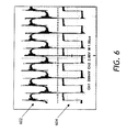
- FIG. 6 is a waveform at the output of the oscillator and comparator circuits
- FIG. 7 is a waveform at the output of the comparator and 1/4 pre-scaler circuits
- FIG. 8 is a waveform at the output of the comparator and 1/32 pre-scaler circuits
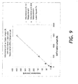
- FIG. 9 is a plot of inductance vs. cable length for a CAT5 cable.
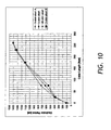
- FIG. 10 is a plot of measured oscillator period vs. cable length.
- FIG. 1 a block diagram of an inductance based length-to-a-fault meter 100 of the present invention is shown comprising an inductive oscillator circuit 102, a comparator andpre-scaler circuit 104, a microprocessor 106, and a display 108.
- a switch 110 is used to switch an input of the oscillator 102 between: (a) an inductive faulted cable under test, or test cable 112 having a local low-resistance fault 113 symbolically shown as a nail driven through the cable 112; and (b) a reference inductor 114 having a reference inductance value of L ref .
- the fault 113 is located at a distance l fault from a measurement point 115.
- the term "low resistance” means a resistance that is significantly lower than a nominal resistance between wires in the cable 112, such that a normal performance of the cable 112 is disrupted.
- the value of the resistance of the low-resistance fault 113 can be from 0 ⁇ to about 100 ⁇ .
- Links 103, 105, and 107 are wires or conductors carrying a corresponding electrical signal.
- the input and the output of the oscillator 102, the input and the output of the comparator and the pre-scaler 104, and the input of the counting register of the microprocessor 106 are electrical terminals electrically coupled to corresponding wires or conductors.
- the inductive oscillator circuit 102 produces oscillations at its output, wherein the period of oscillations and, therefore, the frequency of oscillations depend on an inductance of a circuit coupled to its input.
- the input of the oscillator 102 is coupled to the faulted cable 112 at the point 115, wherein the cable inductance is representative of the distance l fault from the measurement point 115 to the fault point 113.
- the oscillator circuit 102 is constructed in such a way that the effect of a series resistance of the cable 112 on the oscillation period or frequency is largely attenuated by the gain of the oscillator circuit 102.
- the comparator and pre-scaler circuit 104 of FIG. 1 coupled to the output of the oscillator circuit 102 through the link 103, is used to provide a digital signal at the output of the circuit 104, wherein said digital signal is characterized by a period of oscillations that is a multiple of a period of oscillations of the oscillator 102. In other words, said digital signal is characterized by a frequency that is a fraction of a frequency of oscillations of the oscillator circuit 102.
- the circuit 104 and its operation will be also described in more detail below.
- the frequency of oscillations at the output of the circuit 104 is a fraction of a frequency of oscillations of the oscillator which, through the dependence of its frequency of oscillations on the inductance of the cable 112, and the dependence of the inductance of the cable 112 on the length-to-fault l fault , is dependent on l fault .
- the microprocessor 106 After performing the above-described frequency measurement, the microprocessor 106, through the link 107, switches the switch 110 to the upper position in FIG. 1 and proceeds to measure a frequency of oscillations representative of the reference inductance value L ref of the reference inductor 114. The value of l fault is then calculated by taking a ratio of these two measured frequencies.
- any test value based on the oscillation period of the oscillator such as frequency, a pulse duration time, a voltage at the output of a frequency-to-voltage converter, etc.
- a ratio of the test values obtained with a test cable and a reference inductor alternately connected to the input of an oscillator can be used to calculate the value of l fault .
- the test values have to be compared to each other in some way to obtain the value of l fault . For example, a difference of the test values should be used if the test values are proportional to a logarithm of the oscillation period.
- any processing device such as a central processing unit (CPU) of a microcomputer, can be used instead of the microprocessor 106, to perform necessary calculations.
- CPU central processing unit
- an equivalent circuit of an electrical cable 212 having a low-resistance fault 213 comprising a distributed inductance 202, a distributed resistance 204, and a distributed capacitance 206.
- the low-resistance fault 213 short-circuits the capacitors 206 and closes a conductive-inductive loop 208 between terminals 209 and 210.
- the inductance or resistance of the cable 212 to the right side of the fault 213 is irrelevant since it is outside of the loop 208.
- the inductance of the loop 208 is proportional to the length of the cable 212 to the fault l fault .
- the star-coupled cable is not shown in FIG. 2 .
- the resistance of the loop 208 is not proportional to l fault since said resistance also depends of a value of the resistance of the fault 213 which, in general, is unknown and not negligible as compared to a value of the resistance of the cable 212. Since the resistance of the fault 213 is unknown, the oscillator 102 of FIG. 1 is constructed so as to attenuate the impact of a series resistance coupled to its input.
- an oscillation circuit 300 contains two radio-frequency n-p-n transistors Q1 and Q2 connected in common-emitter configuration having a common emitter resistor R1.
- the transistors Q1 and Q2 have resistive collector loads R2 and R3, respectively.
- Positive feedback, or a.c. regeneration, is achieved via phase inversion created by connecting the collector of one transistor to the base of the other transistor in the presence of an inductor L having an inductance L . Regeneration at d.c. is not possible once the inductance L and an electrical current gain ⁇ of the two transistors Q1 and Q2 exceed certain values, which results in an oscillation at start-up.
- the transistors Q1 and Q2 have a sufficiently high gain-bandwidth product, e.g. 1.4GHz or higher, to not affect the oscillation period.
- TC L / R 2 + R 3 + R L / ⁇
- the parameters of the elements shown in FIG. 3 are chosen such that the oscillator is not saturated, so the storage time and the period of oscillations of the oscillator is minimized.
- the cable being measured is connected to the base pins C and B of two transistors Q1 and Q2, respectively, that form a very simple oscillator, which enables the influence of the cable and the fault resistance on the oscillation period to be greatly attenuated by the gain ⁇ of the transistors Q1 and Q2.
- the oscillation time constant TC depending largely on the cable inductance L and the sum resistance R 2 + R 3 of the resistors R2 and R3.
- the oscillator 300 may still be somewhat sensitive to capacitance and resistance of an input circuit coupled to the oscillator between the terminals B and C. Yet the sensitivity of the oscillation period to a relative variation of inductance is much higher than the sensitivity to a relative variation of resistance or capacitance.
- relative variation is understood as a per cent variation, that is, an absolute variation of a parameter divided by its original value.
- the oscillator of the present invention has a number of important advantages over an oscillator taught by Watkins in US Patent 6,646,454 .
- the LMC555 timer-based oscillator described by Watkins is not fast enough if it were adapted to sense a small inductance of the cable.
- the fastest 555 timer in the market has a propagation delay of 200 nanoseconds, or 200 billionths of a second. This is just the propagation delay, without delays from the rest of the oscillator circuit and the cable under test taken into account.
- the oscillator circuit needs to oscillate with a period as short as 60 nanoseconds.
- the overall measurement circuit needs to resolve difference in oscillation period of as short as 5 to 10 nanoseconds. This is why, after a number of failed experiments, an oscillator circuit based on radio frequency bipolar transistors with 1.4GHz gain-bandwidth product was selected for this application.
- the simplicity of the oscillation circuit of the present invention in comparison with the 555 timer circuit, provides sufficiently high oscillation frequency that allows the cable's small inductance of as little as 10uH, that is 10 micro Henry, to be resolved.
- the circuit imposes no upper limit on a measurable cable length as long as the capacitance and series resistance of the cable are sufficiently low.
- a number of inductor-based oscillator circuits can be used for this application.
- the oscillator of FIG. 3 has three important advantages over inductance oscillation circuits employing a wide-band amplifier: a cost-effectiveness advantage, since only a few components are required; an advantage of the influence of the series resistance of the cable and the resistance of the fault on the oscillation period being largely attenuated by the circuit gain; and the advantage of having the oscillation period proportional to the inductance of the test cable, allowing the length-to-fault l fault to be easily determined based on an oscillation parameter measured relative to a reference inductor sample.
- FIG. 4 a circuit diagram of an input circuitry of the length-to-fault meter of the present invention is shown having an oscillator circuit 402 and an input switching circuit 404 comprising an input switch relay 410, a reference inductor 414 having an inductance L ref , a background inductor 406 having an inductance L background , and terminals 411 for connecting a test cable, not shown.
- a link 407 corresponding to the link 107 of FIG. 1 , is used to energize the relay 410 of FIG. 4 and switch the input of the oscillator 402 from the reference inductor 414 to the terminals 411 coupled to the background inductor 406.
- the reference inductor 414 is a relatively small inductor, e.g. less than 400uH.
- the reference inductor can have an inductance of 26uH, representing a 100 feet long twisted pair category 5 (CAT5) cable.
- the inductance L background is preferably less than 80uH. Other values could also be used for another target length-to-fault measurement range.
- the input switch relay 410 is preferably an electromechanical relay or an analog multiplexor.
- the reference inductor 414 eliminates systematic errors via the circuit arrangement wherein both the reference inductor 414 and the test cable, not shown, share the same oscillator circuit and power supply. Due to the fact that the oscillator circuit is shared, manufacturing process variations of Vcc , of the gain ⁇ of the transistors Q1 and Q2, variations of R 1 and R 2 , as well as temperature and aging induced fluctuations of said parameters, affect equally the oscillation periods measured using the reference inductor 414 and using the test cable. By applying Eq.
- TC cable / TC ref L cable / L ref at a condition that the gain ⁇ is high enough so that R re / ⁇ ⁇ ( R 2 + R 3 ) and R cable / ⁇ ⁇ ( R 2 + R 3 ).
- R ref 0.1 ⁇ and ⁇ of 100
- R ref / ⁇ is in the neighborhood of 0.001 ⁇ , which is much smaller than ( R 2 + R 3 ) having a value of 120 ⁇ in a manufactured prototype of the tester.
- R ref / ⁇ is in the neighborhood of 0.7 ⁇ , which is still much smaller than the 120 ⁇ value.
- Eq. (5) allows one to determine L cable and, therefore, the cable length-to-fault once the inductance of a unit length of the test cable is known, by comparing oscillation periods with the test cable and the reference 414 alternately coupled to an input of the oscillator 402. This determination is independent on oscillation period variations caused by supply voltage and component parameter variations, since these variations influence both measurements to an equal extent. The insensitivity to the supply voltage variations is especially important since a field test device is likely to be battery powered.
- the cable length to a low-resistance fault of the cable under test can be calculated simply by multiplying an "equivalent cable length" corresponding to the inductance L ref of the reference inductor 414 by the ratio of the oscillation count measured within the abovementioned gating time window of the microprocessor when the cable under test is coupled to the oscillator 402, to the oscillation count measured within the gating time window of the same duration, when the reference inductor 414 is coupled to the oscillator 402.
- the duration of the gating time window may be adjusted between the measurements of test cable and of the reference, with an appropriate adjustment of the ratio of measured counts.
- the number indicative of the inductance per unit length of a cable can be used to calculate the equivalent cable length mentioned in the previous paragraph.
- This equivalent cable length can be made user-adjustable, such that a user can adjust this number for testing different cables manufactured by different manufacturers.
- This adjustable number is needed because different models of cables may have different values of inductance per unit length.
- l fault T cable T reference ⁇ ⁇ reference ⁇ cable
- T cable and T reference are the oscillation periods of the oscillator having coupled to the input thereof the test cable and the reference inductor, respectively;
- ⁇ reference is an inductance value of the reference inductor;
- ⁇ cable is a per-unit-length inductance of the test cable.
- the reference inductor 414 may be physically a length of a cable of the same type as the cable under test, the length being known to the user; this so called reference cable can be located outside of the tester of the present invention, being connectable through a pair of additional terminals, not shown, similar to the pair of terminals 411.
- the actual periods of oscillation T cable and T reference need not necessarily be determined during the measurement process. They are used in Eqs. (6) and (7) to highlight the fact that the length to fault l fault is proportional to a value representing the ratio of T cable and T reference .
- the microprocessor counts pulses from the pre-scaler 506 within its gating window, with the reference inductor and the cable under test alternately coupled to the input of the oscillator, and then compares the counts to each other, by taking a ratio of the counts. Thus, the number of counts occurred within the gating window is all that needs to be measured.
- the linear model described by Eqs. (5) to (7) above, in which the length to fault l fault is proportional to a measured value such as the oscillation period, provides sufficient measurement accuracy for day-to-day cable measurements. If a higher measurement accuracy is desired, a higher order polynomial model, such as a quadratic model, should be used. In the higher-order polynomial model, multiple coefficients are selected to account for second or third order non-linearity effect.
- FIG. 5 an implementation example of a comparator / pre-scaler 104 of FIG. 1 is presented.
- a circuit diagram of FIG. 5 shows an oscillator 502, a comparator module 504, and a pre-scaler module 506.
- the comparator 502 is, for example, a high-speed comparator AD8561AN manufactured by Analog Devices located in Norwood, Massachusetts, USA. Its function is to remove noise from the oscillation signal of the oscillator by converting the input analog waveform into a clean digital waveform of ones and zeroes.
- the pre-scaler module 506 performs down-counting of the number of pulses produced at the output of the comparator 504, yielding a signal having a period of oscillation being equal to a multiple of periods of the input signal.
- the function of the pre-scaler module 506 is twofold. Firstly, it sums up many periods of the output comparator signal and, therefore, it sums up periods of oscillation of the oscillator 502, effectively performing an averaging function of the oscillation period of the oscillator 502. Secondly, it produces a signal having a low enough frequency to be measurable by a microprocessor, not shown.
- the microprocessor's counter registers have a limited number of bytes, and they may not be capable of accumulating counts generated from the shortest cable, producing the highest count, without a pre-scaler reducing those counts.
- the microprocessor is capable of selecting different numbers of periods of oscillation for the pre-scaler 506 to sum up, for example it can select 32, 64, 128, 256 periods, and so on, effectively broadening the dynamic range of the measurement of the period or frequency of oscillations of the oscillator 502, and therefore, broadening the range of measurable cable lengths.
- the down-conversion is performed by the module 506 such that the microprocessor can handle the range of oscillation counts it needs to accumulate for both the shortest and the longest cable that the tester is constructed to measure.
- the methodology of the present invention is not tied up to a particular range of frequencies.
- the oscillation frequency before the prescaler ranges from 1.52MHz for no cable, wherein said frequency is set by a background inductor, to 200kHz for a 1000 feet long cable coupled to the oscillator input.
- the function of the comparator 504 and the pre-scaler 506 of FIG. 5 will now be illustrated by means of experimentally recorded electrical waveforms.
- a waveform 602 at the output of the oscillator circuit 502 of FIG. 5 and a waveform 604 of FIG. 6 at the output of the comparator circuit 504 of FIG. 5 is shown.
- the voltage scales for the signals 602 and 604 of FIG. 6 are 200mV and 2V per division, respectively.
- the time scale is 1 ⁇ s per division.
- the signal 604 has much less noise and is higher in amplitude than the signal 602.
- FIGS. 7 and 8 The function of the pre-scaler 506 of FIG. 5 is illustrated in FIGS. 7 and 8 .
- FIG. 7 a waveform 704 at the output of the comparator circuit 504 of FIG. 5 and a waveform 706 of FIG. 7 at the output of the pre-scaler circuit 506 of FIG. 5 is shown.
- the voltage scale for the signals 704 and 706 of FIG. 7 is 2V per division.
- the time scale is 4 ⁇ s per division.
- the frequency of the signal 706 is down-counted by a factor of four from the frequency of the signal 704.
- FIG. 8 a waveform 804 at the output of the comparator circuit 504 of FIG. 5 and a waveform 806 of FIG.
- the voltage scale for the signals 804 and 806 of FIG. 8 is 2V per division.
- the time scale is 10 ⁇ s per division.
- the frequency of the signal 806 is down-counted by a factor of thirty-two from the frequency of the signal 804.
- Inductance of CAT5 cables up to the length of 1500 feet was measured at a laboratory of JDS Uniphase Corporation, located at Camarillo, California, USA. The inductance was measured using a LCR meter model 875A from B&K Precision Corporation, located at Yorba Linda, California, USA, to confirm the first-order, or linear relation of the inductance with the cable length.
- FIG. 9 the measured relation between inductance and the distance-to-short at various locations of a CAT5 cable is shown. The measurement was repeated once to determine the repeatability. The physical orientation of the cable was not changed during the second measurement, leaving the measurement error as the only variable. A least square fit was then performed on the data measured. The least square fit is shown with a straight line in FIG. 9 . One can see from FIG. 9 that the dependence is, indeed, close to being linear.
- the unit inductance of the CAT5 cable was found to be approximately 264 nH/ft.
- the oscillation period was measured using a Model 3034B Oscilloscope manufactured by Tektronix Corporation, Richardson, Texas, USA. Four measurements were conducted in the following sequence:
- Second measurement a 5 ⁇ resistive fault was inserted at various lengths of the unshielded CAT5 cable, and the corresponding oscillation periods were measured;
- the method of the present invention does not involve a direct measurement of the inductance of a cable.
- Cable inductance measurement requires a more complex circuit, periodic calibrations, and a higher component count, which can be cost prohibitive.
- the method described comprises counting pulses produced by a simple oscillator circuit having coupled thereto either the cable under test or a reference inductor.
- An important feature of the present invention is a circuit for suppressing a nonreactive component of the cable's electrical characteristics to the measured oscillation period.
- This method can be practiced using a very simple equipment having far less components than a standard inductance meter for measuring both the phase and magnitude responses of a device-under-test (DUT) at various frequencies.
- the device of the present invention can be used to measure a cable length to any low-resistance fault, however caused.
Landscapes
- Physics & Mathematics (AREA)
- General Physics & Mathematics (AREA)
- Measurement Of Resistance Or Impedance (AREA)
Applications Claiming Priority (1)
| Application Number | Priority Date | Filing Date | Title |
|---|---|---|---|
| US5321308P | 2008-05-14 | 2008-05-14 |
Publications (1)
| Publication Number | Publication Date |
|---|---|
| EP2120058A2 true EP2120058A2 (de) | 2009-11-18 |
Family
ID=41087378
Family Applications (1)
| Application Number | Title | Priority Date | Filing Date |
|---|---|---|---|
| EP09159922A Withdrawn EP2120058A2 (de) | 2008-05-14 | 2009-05-11 | Ortung einer Störung mit niedrigem Widerstand in einem elektrischen Kabel |
Country Status (2)
| Country | Link |
|---|---|
| US (1) | US20090284264A1 (de) |
| EP (1) | EP2120058A2 (de) |
Cited By (1)
| Publication number | Priority date | Publication date | Assignee | Title |
|---|---|---|---|---|
| CN118914785A (zh) * | 2024-10-10 | 2024-11-08 | 合肥工业大学 | 一种基于反射系数和阻抗谱的电缆绝缘缺陷检测方法 |
Families Citing this family (10)
| Publication number | Priority date | Publication date | Assignee | Title |
|---|---|---|---|---|
| JP5535766B2 (ja) * | 2010-05-27 | 2014-07-02 | ラピスセミコンダクタ株式会社 | タイマー回路 |
| JP2015002554A (ja) * | 2013-06-18 | 2015-01-05 | 船井電機株式会社 | 有線通信装置および有線通信方法 |
| US10116351B2 (en) * | 2015-01-20 | 2018-10-30 | Semiconductor Components Industries, Llc | Pollution detection circuit for data lines and method thereof |
| US10684319B2 (en) * | 2015-07-20 | 2020-06-16 | International Business Machines Corporation | Tuning a testing apparatus for measuring skew |
| US10162002B2 (en) | 2015-07-20 | 2018-12-25 | International Business Machines Corporation | Tuning a testing apparatus for measuring skew |
| DE102015216474A1 (de) * | 2015-08-28 | 2017-03-02 | Leoni Kabel Holding Gmbh | Überwachungssystem, Sicherheitskabel und Schlauch für ein solches und Verfahren zum Betrieb eines Überwachungssystems |
| DE102017202631A1 (de) | 2017-02-17 | 2018-08-23 | Leoni Kabel Gmbh | Überwachungssystem sowie Kabel |
| FR3080914B1 (fr) * | 2018-05-07 | 2020-11-20 | Safran Electronics & Defense | Procede de mesure utilisant un capteur de proximite inductif relie a un cable |
| CN114200344B (zh) * | 2021-12-02 | 2024-10-18 | 国网江苏省电力有限公司淮安供电分公司 | 一种高压电缆终端接地系统缺陷电压和电流特征分析方法 |
| CN115877124A (zh) * | 2022-11-29 | 2023-03-31 | 国网江苏省电力有限公司电力科学研究院 | 用于中压电缆的在线监测方法及装置 |
Citations (2)
| Publication number | Priority date | Publication date | Assignee | Title |
|---|---|---|---|---|
| US6646454B2 (en) | 2002-01-07 | 2003-11-11 | Test-Um, Inc. | Electronic apparatus and method for measuring length of a communication cable |
| US7076374B2 (en) | 2004-07-29 | 2006-07-11 | The Boeing Company | Methods and systems for detecting and locating damage in a wire |
Family Cites Families (18)
| Publication number | Priority date | Publication date | Assignee | Title |
|---|---|---|---|---|
| US2315450A (en) * | 1941-06-14 | 1943-03-30 | Bell Telephone Labor Inc | Method of and apparatus for locating transmission faults |
| US2738434A (en) * | 1952-09-10 | 1956-03-13 | Muirhead & Co Ltd | Induction generators |
| GB1352124A (en) * | 1970-07-08 | 1974-05-08 | Electricity Council | Cable fault location |
| US4165482A (en) * | 1976-04-06 | 1979-08-21 | The Electricity Council | Cable fault location |
| US4307267A (en) * | 1980-06-16 | 1981-12-22 | Bell Telephone Laboratories, Incorporated | Testing loaded transmission lines |
| US5128619A (en) * | 1989-04-03 | 1992-07-07 | Bjork Roger A | System and method of determining cable characteristics |
| US5068614A (en) * | 1990-11-05 | 1991-11-26 | Tektronix, Inc. | Swept frequency domain relectometry enhancement |
| US5189375A (en) * | 1991-06-04 | 1993-02-23 | United States Of America As Represented By The Secretary Of The Army | Inductive cable resistance tester |
| US5339022A (en) * | 1992-09-24 | 1994-08-16 | The Whitaker Corporation | Capacitive cable length indicator |
| US6144721A (en) * | 1996-01-05 | 2000-11-07 | Communications Technology Corporation | Apparatus and method for line pair testing and fault diagnostics |
| US5977773A (en) * | 1997-08-15 | 1999-11-02 | The United States Of America As Represented By The Administrator Of The National Aeronautics And Space Administration | Non-intrusive impedance-based cable tester |
| US6181140B1 (en) * | 1998-06-08 | 2001-01-30 | Norscan Inc. | Method of estimating the location of a cable break including a means to measure resistive fault levels for cable sections |
| CA2312509C (en) * | 2000-06-27 | 2003-11-18 | Norscan Instruments Ltd. | Open cable locating for sheathed cables |
| US6771076B1 (en) * | 2000-06-30 | 2004-08-03 | Andrew L. Smith | Method and apparatus for measurement of length of cable having fixed impedance |
| US6691051B2 (en) * | 2001-08-14 | 2004-02-10 | Tektronix, Inc. | Transient distance to fault measurement |
| US7511582B2 (en) * | 2002-08-12 | 2009-03-31 | Broadcom Corporation | Voltage controlled oscillator for use in phase locked loop |
| AU2003294419A1 (en) * | 2002-11-19 | 2004-06-15 | University Of Utah | Device and method for detecting anomolies in a wire and related sensing methods |
| US7282927B1 (en) * | 2006-06-21 | 2007-10-16 | Eastman Kodak Company | Use of a configurable electronic controller for capacitance measurements and cable break detection |
-
2009
- 2009-05-11 EP EP09159922A patent/EP2120058A2/de not_active Withdrawn
- 2009-05-13 US US12/465,213 patent/US20090284264A1/en not_active Abandoned
Patent Citations (2)
| Publication number | Priority date | Publication date | Assignee | Title |
|---|---|---|---|---|
| US6646454B2 (en) | 2002-01-07 | 2003-11-11 | Test-Um, Inc. | Electronic apparatus and method for measuring length of a communication cable |
| US7076374B2 (en) | 2004-07-29 | 2006-07-11 | The Boeing Company | Methods and systems for detecting and locating damage in a wire |
Cited By (1)
| Publication number | Priority date | Publication date | Assignee | Title |
|---|---|---|---|---|
| CN118914785A (zh) * | 2024-10-10 | 2024-11-08 | 合肥工业大学 | 一种基于反射系数和阻抗谱的电缆绝缘缺陷检测方法 |
Also Published As
| Publication number | Publication date |
|---|---|
| US20090284264A1 (en) | 2009-11-19 |
Similar Documents
| Publication | Publication Date | Title |
|---|---|---|
| EP2120058A2 (de) | Ortung einer Störung mit niedrigem Widerstand in einem elektrischen Kabel | |
| US6856138B2 (en) | Time-domain reflectometer for testing terminated network cable | |
| US5633801A (en) | Pulse-based impedance measurement instrument | |
| US7768292B1 (en) | Non-invasive power supply tester | |
| US7385410B2 (en) | Method of and apparatus for testing for integrated circuit contact defects | |
| JP4689125B2 (ja) | 自動試験装置における改良試験及び較正回路及び方法 | |
| JP3816975B2 (ja) | 製造欠陥分析装置 | |
| EP0947844A2 (de) | Methode und Apparat zum fernbedient Änderen von Signalkarakteristieken einer Signalgenerators | |
| US20110238383A1 (en) | One-Port De-embedding Using Time Domain Substitution | |
| US12320853B2 (en) | Systems and methods for automatic time domain reflectometer measurement on a uni-directional drive channel | |
| JPH0621786B2 (ja) | 線路長測定装置 | |
| US10761130B1 (en) | Voltage driver circuit calibration | |
| CN202166702U (zh) | 自动测试系统 | |
| CN106249066B (zh) | 用于校准电缆的方法和相应的测量设备 | |
| US20110234239A1 (en) | Two-Port De-Embedding Using Time Domain Substitution | |
| US20110156730A1 (en) | Chip-based prober for high frequency measurements and methods of measuring | |
| US6483318B1 (en) | Electric circuit providing selectable short circuit for instrumentation applications | |
| US20220236325A1 (en) | Device interface board compliance testing using impedance response profiling | |
| US9217769B2 (en) | Ring oscillator testing with power sensing resistor | |
| Ovidiu-Catalin et al. | Modeling and Simulation of a Compensation PCB for Oscilloscope Probes | |
| US20070197169A1 (en) | Systems and methods for transmitter and channel characterization | |
| Saadeddine et al. | New reference systems for the calibration of HV impulses at LNE | |
| US20250347729A1 (en) | Analyzing bundles of wires | |
| US20240329110A1 (en) | Equipment design and testing using in-situ on-die time-domain reflectometry | |
| Baros et al. | Introduction to EMC simulations of analog ICs |
Legal Events
| Date | Code | Title | Description |
|---|---|---|---|
| PUAI | Public reference made under article 153(3) epc to a published international application that has entered the european phase |
Free format text: ORIGINAL CODE: 0009012 |
|
| AK | Designated contracting states |
Kind code of ref document: A2 Designated state(s): AT BE BG CH CY CZ DE DK EE ES FI FR GB GR HR HU IE IS IT LI LT LU LV MC MK MT NL NO PL PT RO SE SI SK TR |
|
| STAA | Information on the status of an ep patent application or granted ep patent |
Free format text: STATUS: THE APPLICATION HAS BEEN WITHDRAWN |
|
| 18W | Application withdrawn |
Effective date: 20110516 |