EP0947844A2 - Methode und Apparat zum fernbedient Änderen von Signalkarakteristieken einer Signalgenerators - Google Patents
Methode und Apparat zum fernbedient Änderen von Signalkarakteristieken einer Signalgenerators Download PDFInfo
- Publication number
- EP0947844A2 EP0947844A2 EP99200819A EP99200819A EP0947844A2 EP 0947844 A2 EP0947844 A2 EP 0947844A2 EP 99200819 A EP99200819 A EP 99200819A EP 99200819 A EP99200819 A EP 99200819A EP 0947844 A2 EP0947844 A2 EP 0947844A2
- Authority
- EP
- European Patent Office
- Prior art keywords
- signal
- electrical conductor
- signal generator
- generator
- change
- Prior art date
- Legal status (The legal status is an assumption and is not a legal conclusion. Google has not performed a legal analysis and makes no representation as to the accuracy of the status listed.)
- Withdrawn
Links
Images
Classifications
-
- G—PHYSICS
- G01—MEASURING; TESTING
- G01R—MEASURING ELECTRIC VARIABLES; MEASURING MAGNETIC VARIABLES
- G01R31/00—Arrangements for testing electric properties; Arrangements for locating electric faults; Arrangements for electrical testing characterised by what is being tested not provided for elsewhere
- G01R31/50—Testing of electric apparatus, lines, cables or components for short-circuits, continuity, leakage current or incorrect line connections
Definitions
- This invention relates to remote changing of the characteristics of a signal produced by a signal generator.
- This invention has particular application to locating or identifying one or more electrical conductors such as household wiring, commercial wiring, and industrial wiring installations. Examples of such wiring are TV coax and antenna wires, all types of electrical wires, telephone and data wires, environmental control wires, etc. No instrumentation is needed at the remote end of the wiring under test to effect the change in signal characteristic.
- the 'tone generator' is connected to the isolated end of the pair of wires and the receiver is placed near the group of wires at the other end.
- the receiver is positioned closely adjacent to each wire sequentially, and when the tone output of the receiver is loudest, one might reasonably conclude that the receiver is closest to the wire in question.
- the next process usually followed by the person interested in finding the wires is to individually test the wires by placing a short on the known end and measuring for that short on the possible unknown ends. This process requires that the person make several trips from one end of the wiring to the other. These trips can involve flights of stairs, or even be between buildings. This is clearly an inefficient process.
- This invention provides a solution to the problem of positive identification of wires without regard to the characteristics of the wire type or the intended use of the wires, and with no additional instrumentation being required at the remote end.
- a signal generator or detector employed in other types of equipment such as multimeters or time domain reflectometers (TDR's)
- TDR's time domain reflectometers
- This invention provides a method for changing the characteristics of the signal generated by a 'tone generator' when a detector coupled to that 'tone generator' detects a significant change in the impedance of the wire or pair of wires it is connected to.
- impedance change as the 'trigger' for the signal characteristic change, the user does not need any instrumentation at the remote end to effect the change.
- This impedance change can be accomplished by merely shorting and then opening the ends of the wire pair suspected to be the wire pair of interest.
- the resultant change in the 'tone generator' signal characteristics is non-transient; that is, the change remains in effect until such time that another change in the detector output causes another change in the signal characteristic.
- An exemplary embodiment of this invention contains a versatile signal generator, an open/short detector, and a simple flip flop. These circuits are coupled such that whenever the detector output changes from short to open, it flips the state of the flip flop. The output of the flip flop controls one of the characteristics of the signal generator such as its frequency. Thus, in actual use, when the user first shorts and then opens a pair of wires connected to the device, the tone heard in the receiver will change and hold its changed frequency.
- the two conductors connected to the generator be of the same type or length, just that there be two conductors.
- the other conductor could, for example, be earth ground, a water pipe, or any other common conductor available at both ends of the wire in question.
- this invention can be used in a stand-alone signal generator/detector whose sole purpose is to generate this tone signal and respond to indications from its detector
- the preferred approach is to employ the invention in a more versatile device such as a multimeter or TDR that contains among other elements a versatile signal generator, a detector, and a control circuit that directs the operation of the device.
- this invention can be implemented totally in the software of the control circuit at minimal or even no additional cost.
- detection mechanisms can be used when practicing this invention, such as a multimeter to detect resistance or voltage, or a TDR to measure length or termination type (Open, Shorted, Terminated).
- TDR to measure length or termination type
- Many types of signal generators and characteristics can also be used. It is suggested that 'volume' not be utilized as a changeable characteristic since it is the inability of the process to distinguish relative signal strengths that causes the identification problem with respect to prior art devices in the first place.
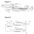
- Fig. 1 illustrates a simple, typical household wiring or cable installation. Each room is wired separately to a common connection box located in the back yard. Utilizing the principles of the present invention the installer could place the signal generator 107 on wire 103 in the upstairs front bedroom and then travel down to the back yard connection box 105. With his or her receiver 106, the individual could probe each of the four wires at that connection box to try and determine which of the cables extends from the upstairs front bedroom. When all four of the cables cause approximately the same tone indication (as would often be the case), he or she could then sequentially short and open each pair of wires until the characteristics of the tone change. At that point, there would be positive identification of the wire pair.
- a versatile signal generator 201 couples its output 202 to the cable connection 203 and to the input 204 of the open/short detector 205.
- the detector 205 will set its output 206 to a logic 1 if it detects an open circuit at the cable connection 203, otherwise its output is logic 0.
- This detector output 206 is coupled to the clock input of toggle flip flop 207 such that every time the detector output changes from a logic 0 to a logic 1 the output 208 of the flip flop will change its state.
- This output 208 is coupled to the frequency control input 209 of the versatile signal generator 201.
- the output 208 of the flip flop is at some particular state, 1 or 0.
- This causes the signal generator 201 to be generating a signal of the frequency that corresponds to that flip flop state of 0, for example 1000 Hz.
- the detector 205 detects that short and changes its output 206 to a logic 0.
- the detector output 206 When the user removes the short circuit from the connection pins 203, the detector output 206 will change to a logic 1. This change to a logic 1 will cause the toggle flip flop 207 to change its output state to a logic 1. Now the signal generator will be outputting a signal of the frequency that corresponds to the flip flop state of 1, 2000 Hz for example. If the user then re-applies and then removes the short circuit from the connection pins 203, the detector output 206 will change to 0 and then to 1. This will once again toggle the flip flop and the output 208 of the flip flop will now be 0. This will cause the signal generator 201 to output the signal of frequency 1000 Hz, corresponding to the state 1 of the flip flop. Note that this particular implementation only has two states for the characteristic frequency of the signal generator. However this invention encompasses a device that has any number of characteristic states more than two.
- this description shows the toggle flip flop 207 changing its state when its clock changes from 0 to 1, reflecting the detection of the removal of a short on wires 203
- this invention also encompasses the situation where the flip flop 207 is of such a type that it changes its state when its clock changes from 1 to 0, reflecting the detection of a short on wires 203.
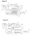
- Fig. 3 shows a common multimeter with the addition of a versatile signal generator 310 to its analog circuit 304, and the addition of an open/short threshold detector 311 and toggle flip flop 312 to its control circuit 302.
- the mode switch 306 is set by the user to the mode of operation desired, such as the measurement of Amps, Ohms or Volts.
- This mode switch 306 is read by the control circuit 302 which then sends appropriate control signals to the analog circuit 304.
- This analog circuit then performs the appropriate measurement of its environment via its test leads 305. The result of this measurement is sent back to the control circuit 302 where it is converted to the appropriate form for display on the readout 303.
- the mode switch 306 would have an additional position which, when read by the control circuit 302 would enable the output of the ohm meter section 307 to be examined by the open/short threshold detector 311 and a sufficiently low reading from the ohm meter section 307 would set the output of the detector 311 and toggle the flip flop 312.
- the changed state of the flip flop 312 is coupled to the signal generator 310 so as to change the specified characteristic of the signal generator 310.
- the analog circuit 304 and the control circuit 302 are constructed with ASICs (Application Specific Integrated Circuit) and a small quantity of individual components. In some cases the two circuits are constructed within the same ASIC. It is a straightforward task for anyone skilled in the arts of multimeter design and ASIC design to include a versatile signal generator 310 in the analog circuit 304 and the open/short detector 311 and toggle flip flop 312 in the control circuit 302.
- ASICs Application Specific Integrated Circuit
- Fig. 4 shows an alternative embodiment wherein the invention is incorporated within a conventional TDR cable tester using only additional software and no additional hardware.
- the cost of adding this new capability to the TDR could be virtually zero.
- the versatile signal generator already exists as the software controlled TDR pulse generator 409. The rate and pattern of repetition of the TDR pulse is already under the control of the control software 402.
- the detector also already exists as the TDR pulse receiver 407 and TDRs already have open/short threshold software 411 as part of their capability. All that would be needed is additional control software to monitor the state of the open/short threshold logic 411 and change the appropriate characteristic of the TDR pulse generator 409 when the open/short state changes from short to open.
- additional control software can readily be devised by one skilled in the TDR art.
- the appropriate pulse generator changeable characteristic could, for example, be the TDR pulse width, the pulse repetition rate, or the pulse repetition pattern.
Landscapes
- Physics & Mathematics (AREA)
- General Physics & Mathematics (AREA)
- Arrangements For Transmission Of Measured Signals (AREA)
- Testing Of Short-Circuits, Discontinuities, Leakage, Or Incorrect Line Connections (AREA)
Applications Claiming Priority (2)
| Application Number | Priority Date | Filing Date | Title |
|---|---|---|---|
| US09/050,652 US6160405A (en) | 1998-03-30 | 1998-03-30 | Method and apparatus for remotely changing signal characteristics of a signal generator |
| US50652 | 1998-03-30 |
Publications (2)
| Publication Number | Publication Date |
|---|---|
| EP0947844A2 true EP0947844A2 (de) | 1999-10-06 |
| EP0947844A3 EP0947844A3 (de) | 1999-12-08 |
Family
ID=21966545
Family Applications (1)
| Application Number | Title | Priority Date | Filing Date |
|---|---|---|---|
| EP99200819A Withdrawn EP0947844A3 (de) | 1998-03-30 | 1999-03-17 | Methode und Apparat zum fernbedient Änderen von Signalkarakteristieken einer Signalgenerators |
Country Status (2)
| Country | Link |
|---|---|
| US (2) | US6160405A (de) |
| EP (1) | EP0947844A3 (de) |
Families Citing this family (29)
| Publication number | Priority date | Publication date | Assignee | Title |
|---|---|---|---|---|
| US7749089B1 (en) | 1999-02-26 | 2010-07-06 | Creative Kingdoms, Llc | Multi-media interactive play system |
| US7099621B1 (en) * | 1999-06-25 | 2006-08-29 | Cocomo Mb Communications, Inc. | Electromagnetic field communications system for wireless networks |
| US6600896B2 (en) * | 1999-06-25 | 2003-07-29 | Cocomo Mb Communications, Inc. | Exciter system and excitation methods for communications within and very near to vehicles |
| US7878905B2 (en) | 2000-02-22 | 2011-02-01 | Creative Kingdoms, Llc | Multi-layered interactive play experience |
| US6761637B2 (en) | 2000-02-22 | 2004-07-13 | Creative Kingdoms, Llc | Method of game play using RFID tracking device |
| US7445550B2 (en) | 2000-02-22 | 2008-11-04 | Creative Kingdoms, Llc | Magical wand and interactive play experience |
| US6891512B2 (en) * | 2000-12-27 | 2005-05-10 | Cocomo Mb Cojmmunications, Inc. | Antenna |
| US7066781B2 (en) | 2000-10-20 | 2006-06-27 | Denise Chapman Weston | Children's toy with wireless tag/transponder |
| US6956534B2 (en) * | 2000-12-27 | 2005-10-18 | Cocomo Mb Communications, Inc. | Method and apparatus for improving antenna efficiency |
| US6653845B2 (en) * | 2002-02-25 | 2003-11-25 | Daimlerchrysler Corporation | Addressable open connector test circuit |
| US20070066396A1 (en) | 2002-04-05 | 2007-03-22 | Denise Chapman Weston | Retail methods for providing an interactive product to a consumer |
| US6967566B2 (en) | 2002-04-05 | 2005-11-22 | Creative Kingdoms, Llc | Live-action interactive adventure game |
| US6922060B1 (en) * | 2002-07-23 | 2005-07-26 | Alstom Technology Ltd. | Method for detecting partial conductor short circuits, and device for performing and using the method |
| US7674184B2 (en) | 2002-08-01 | 2010-03-09 | Creative Kingdoms, Llc | Interactive water attraction and quest game |
| US6756619B2 (en) | 2002-08-26 | 2004-06-29 | Micron Technology, Inc. | Semiconductor constructions |
| US6801043B2 (en) * | 2002-12-20 | 2004-10-05 | Intel Corporation | Time domain reflectometry based transmitter equalization |
| US9446319B2 (en) | 2003-03-25 | 2016-09-20 | Mq Gaming, Llc | Interactive gaming toy |
| US20050168392A1 (en) * | 2004-01-05 | 2005-08-04 | Cocomo Mb Communications, Inc. | Antenna efficiency |
| US7030623B1 (en) | 2004-02-03 | 2006-04-18 | Kevin Carpenter | Electrical short tracing apparatus and method |
| US8313379B2 (en) | 2005-08-22 | 2012-11-20 | Nintendo Co., Ltd. | Video game system with wireless modular handheld controller |
| JP4805633B2 (ja) | 2005-08-22 | 2011-11-02 | 任天堂株式会社 | ゲーム用操作装置 |
| US7927216B2 (en) | 2005-09-15 | 2011-04-19 | Nintendo Co., Ltd. | Video game system with wireless modular handheld controller |
| JP4262726B2 (ja) | 2005-08-24 | 2009-05-13 | 任天堂株式会社 | ゲームコントローラおよびゲームシステム |
| US8870655B2 (en) | 2005-08-24 | 2014-10-28 | Nintendo Co., Ltd. | Wireless game controllers |
| US8308563B2 (en) | 2005-08-30 | 2012-11-13 | Nintendo Co., Ltd. | Game system and storage medium having game program stored thereon |
| US8157651B2 (en) | 2005-09-12 | 2012-04-17 | Nintendo Co., Ltd. | Information processing program |
| JP4151982B2 (ja) | 2006-03-10 | 2008-09-17 | 任天堂株式会社 | 動き判別装置および動き判別プログラム |
| JP5127242B2 (ja) | 2007-01-19 | 2013-01-23 | 任天堂株式会社 | 加速度データ処理プログラムおよびゲームプログラム |
| US9071912B1 (en) | 2013-02-08 | 2015-06-30 | Clear-Com Llc | Audio test tool |
Family Cites Families (17)
| Publication number | Priority date | Publication date | Assignee | Title |
|---|---|---|---|---|
| GB1352124A (en) * | 1970-07-08 | 1974-05-08 | Electricity Council | Cable fault location |
| US4130794A (en) * | 1976-11-05 | 1978-12-19 | Cox C Eugene | Methods and means for identifying and testing circuit connections |
| JPS5848871A (ja) * | 1981-09-02 | 1983-03-22 | Dainichi Nippon Cables Ltd | 多心ケ−ブルの電気試験装置 |
| US4524320A (en) * | 1983-06-17 | 1985-06-18 | Gary A. Harrelson | Conductor identifying probe and voltage supply device |
| US4563636A (en) * | 1983-12-12 | 1986-01-07 | Hewlett-Packard Company | Connection verification between circuit board and circuit tester |
| DE3533479A1 (de) * | 1985-09-19 | 1987-03-26 | Seba Mess Ortungstech | Verfahren zum ueberwachen eines objektes mit hilfe einer signalleitung sowie impuls-messgeraet zur durchfuehrung dieses verfahrens |
| US4862491A (en) * | 1987-04-14 | 1989-08-29 | Teletech Pty. Ltd. | Remote disconnection and short-circuiting apparatus and method |
| US5131028A (en) * | 1987-11-04 | 1992-07-14 | Chambers Charles W | Methods and apparatus for providing reciprocal impedance conversion |
| GB2215065A (en) * | 1988-02-09 | 1989-09-13 | Edwyn Paul Dark | Tapping-out meter unit |
| US5122800A (en) * | 1989-01-26 | 1992-06-16 | Harald Philipp | Variable successive approximation converter |
| US5268644A (en) * | 1990-04-03 | 1993-12-07 | Ford Motor Company | Fault detection and isolation in automotive wiring harness by time-domain reflectometry |
| EP0541843B1 (de) * | 1991-11-12 | 1997-01-15 | Molex Incorporated | Drahtanwesenheits- und Identifiziersystem |
| US5307398A (en) * | 1992-03-18 | 1994-04-26 | Joseph Contonzo | Remote controlled tone generator system |
| US5436554A (en) * | 1992-09-04 | 1995-07-25 | Decker, Jr.; Harold J. | Computer controlled cable tester |
| US5444695A (en) * | 1993-01-11 | 1995-08-22 | Forte Networks, Inc. | Token ring local area network testing apparatus providing station history information |
| US5457441A (en) * | 1993-06-04 | 1995-10-10 | Progressive Electronics, Inc. | Inductive amplifier having two-terminal auto-on function |
| US5376888A (en) * | 1993-06-09 | 1994-12-27 | Hook; William R. | Timing markers in time domain reflectometry systems |
-
1998
- 1998-03-30 US US09/050,652 patent/US6160405A/en not_active Expired - Lifetime
-
1999
- 1999-03-17 EP EP99200819A patent/EP0947844A3/de not_active Withdrawn
-
2000
- 2000-08-31 US US09/652,424 patent/US6323654B1/en not_active Expired - Lifetime
Also Published As
| Publication number | Publication date |
|---|---|
| EP0947844A3 (de) | 1999-12-08 |
| US6160405A (en) | 2000-12-12 |
| US6323654B1 (en) | 2001-11-27 |
Similar Documents
| Publication | Publication Date | Title |
|---|---|---|
| US6160405A (en) | Method and apparatus for remotely changing signal characteristics of a signal generator | |
| US5420512A (en) | Electronic cable testing system | |
| EP1387176B1 (de) | Zeitbereichsreflektometer zum Prüfen von terminierten Netzwerkkabeln | |
| US6954076B2 (en) | Aircraft multi-function wire and insulation tester | |
| EP1395840B1 (de) | Fehlerdetektionssystem und -verfahren | |
| US5268644A (en) | Fault detection and isolation in automotive wiring harness by time-domain reflectometry | |
| US3944914A (en) | Fault detection method and apparatus for multiconductor cables | |
| US4446421A (en) | Apparatus and method for locating faults in cables | |
| US6859041B2 (en) | Methods for locating faults in aircraft branch conductors and determining the distance to the faults | |
| US7598721B2 (en) | Locating a cable using synchronization portion and data portion of a tone packet of a system | |
| JP5167568B2 (ja) | 分電盤の分岐回路接続チェック装置 | |
| US5914608A (en) | Method and apparatus for tracing coaxial cables | |
| US7010096B1 (en) | Remote testing of a communications line | |
| GB2444850A (en) | An apparatus for assisting measurement of the resistances of LV ring main circuits | |
| US3037161A (en) | Method and apparatus for locating faults in transmission lines | |
| US12368797B2 (en) | Telephone line testing apparatus with remote control | |
| US6016058A (en) | In-service wiring verification circuitry | |
| CN109581147A (zh) | 通过恒流源检测机动车数据电缆的检测设备和检测方法 | |
| RU2142142C1 (ru) | Устройство для определения места повреждения линий электропередачи и связи | |
| US6333625B1 (en) | Fault localizing and identifying device for electric systems | |
| JPH0882648A (ja) | 接続ケーブルの断線検出装置 | |
| JPH05180892A (ja) | 複数導線の導通検査方法および装置 | |
| JP2002078130A (ja) | ケーブル検査方法および装置 | |
| JPH07336277A (ja) | 電力線相試験方法及び装置 | |
| JPH05322953A (ja) | 複数導線の導通検査方法およびこれに用いる接続装置 |
Legal Events
| Date | Code | Title | Description |
|---|---|---|---|
| PUAI | Public reference made under article 153(3) epc to a published international application that has entered the european phase |
Free format text: ORIGINAL CODE: 0009012 |
|
| AK | Designated contracting states |
Kind code of ref document: A2 Designated state(s): AT BE CH CY DE DK ES FI FR GB GR IE IT LI LU MC NL PT SE |
|
| AX | Request for extension of the european patent |
Free format text: AL;LT;LV;MK;RO;SI |
|
| PUAL | Search report despatched |
Free format text: ORIGINAL CODE: 0009013 |
|
| AK | Designated contracting states |
Kind code of ref document: A3 Designated state(s): AT BE CH CY DE DK ES FI FR GB GR IE IT LI LU MC NL PT SE |
|
| AX | Request for extension of the european patent |
Free format text: AL;LT;LV;MK;RO;SI |
|
| RIC1 | Information provided on ipc code assigned before grant |
Free format text: 6G 01R 31/02 A, 6G 01R 31/08 B |
|
| 17P | Request for examination filed |
Effective date: 20000515 |
|
| AKX | Designation fees paid |
Free format text: AT BE CH CY DE DK ES FI FR GB GR IE IT LI LU MC NL PT SE |
|
| 17Q | First examination report despatched |
Effective date: 20011121 |
|
| STAA | Information on the status of an ep patent application or granted ep patent |
Free format text: STATUS: THE APPLICATION IS DEEMED TO BE WITHDRAWN |
|
| 18D | Application deemed to be withdrawn |
Effective date: 20020403 |