EP2119892A2 - Procédé de contrôle d'un point de réglage pour extraire l'air d'un compresseur pour fournir d'air de refroidissement de turbine dans une turbine à gaz - Google Patents
Procédé de contrôle d'un point de réglage pour extraire l'air d'un compresseur pour fournir d'air de refroidissement de turbine dans une turbine à gaz Download PDFInfo
- Publication number
- EP2119892A2 EP2119892A2 EP09159774A EP09159774A EP2119892A2 EP 2119892 A2 EP2119892 A2 EP 2119892A2 EP 09159774 A EP09159774 A EP 09159774A EP 09159774 A EP09159774 A EP 09159774A EP 2119892 A2 EP2119892 A2 EP 2119892A2
- Authority
- EP
- European Patent Office
- Prior art keywords
- stage
- compressor
- air
- compressed air
- ejector
- Prior art date
- Legal status (The legal status is an assumption and is not a legal conclusion. Google has not performed a legal analysis and makes no representation as to the accuracy of the status listed.)
- Withdrawn
Links
Images

Classifications
-
- F—MECHANICAL ENGINEERING; LIGHTING; HEATING; WEAPONS; BLASTING
- F02—COMBUSTION ENGINES; HOT-GAS OR COMBUSTION-PRODUCT ENGINE PLANTS
- F02C—GAS-TURBINE PLANTS; AIR INTAKES FOR JET-PROPULSION PLANTS; CONTROLLING FUEL SUPPLY IN AIR-BREATHING JET-PROPULSION PLANTS
- F02C9/00—Controlling gas-turbine plants; Controlling fuel supply in air- breathing jet-propulsion plants
- F02C9/16—Control of working fluid flow
- F02C9/18—Control of working fluid flow by bleeding, bypassing or acting on variable working fluid interconnections between turbines or compressors or their stages
-
- F—MECHANICAL ENGINEERING; LIGHTING; HEATING; WEAPONS; BLASTING
- F02—COMBUSTION ENGINES; HOT-GAS OR COMBUSTION-PRODUCT ENGINE PLANTS
- F02C—GAS-TURBINE PLANTS; AIR INTAKES FOR JET-PROPULSION PLANTS; CONTROLLING FUEL SUPPLY IN AIR-BREATHING JET-PROPULSION PLANTS
- F02C6/00—Plural gas-turbine plants; Combinations of gas-turbine plants with other apparatus; Adaptations of gas- turbine plants for special use
- F02C6/04—Gas-turbine plants providing heated or pressurised working fluid for other apparatus, e.g. without mechanical power output
- F02C6/06—Gas-turbine plants providing heated or pressurised working fluid for other apparatus, e.g. without mechanical power output providing compressed gas
- F02C6/08—Gas-turbine plants providing heated or pressurised working fluid for other apparatus, e.g. without mechanical power output providing compressed gas the gas being bled from the gas-turbine compressor
-
- F—MECHANICAL ENGINEERING; LIGHTING; HEATING; WEAPONS; BLASTING
- F02—COMBUSTION ENGINES; HOT-GAS OR COMBUSTION-PRODUCT ENGINE PLANTS
- F02C—GAS-TURBINE PLANTS; AIR INTAKES FOR JET-PROPULSION PLANTS; CONTROLLING FUEL SUPPLY IN AIR-BREATHING JET-PROPULSION PLANTS
- F02C7/00—Features, components parts, details or accessories, not provided for in, or of interest apart form groups F02C1/00 - F02C6/00; Air intakes for jet-propulsion plants
- F02C7/12—Cooling of plants
- F02C7/16—Cooling of plants characterised by cooling medium
- F02C7/18—Cooling of plants characterised by cooling medium the medium being gaseous, e.g. air
Definitions
- the invention relates generally to extracting compressor air to provide cooling air for a turbine in a gas turbine and, more particularly to establishing control set points for the extraction of compressor air.
- air is extracted from one or more stages of the compressor and applied to cool the turbine.
- the extraction of compressor air is commonly referred to as bleeding air from the compressor.
- the extracted compressor air is applied as cooling air that passes through internal cooling passages to the turbine blades and buckets.
- the air extracted from the compressor for turbine cooling reduces the amount of air flowing through the compressor and to the combustion section of the gas turbine.
- This reduction in compressed air to the combustor may, at times, have under desirable effects on the performance of the combustor and the total performance of the gas turbine.
- Control systems are employed to regulate the extraction of compressor air to minimize these undesirable effects on the performance of the gas turbine and ensure that adequate cooling air reaches the turbine blades and buckets.
- An approach to regulating the extraction of compressor air is to extract air from two or more stages of the compressor. Air extracted from the lower pressure stage of a compressor tends to have a lesser effect on the performance of the gas turbine than does air extracted from a higher pressure stage. By adjusting the relative proportions of air extracted from the two compressor stages, the control system can reduce or increase the effect of extraction of compressor air on the performance of the gas turbine and provide sufficient cooling air for the turbine.
- Air ejectors are conventionally used to combine air at different pressures, such as air extracted from different stages of a compressor.
- An ejector has been used to combine air from different stages of a compressor to provide turbine cooling air.
- compressor air has been extracted from a thirteenth stage of the compressor to cool a second stage nozzle of the turbine.
- Compressor air has also been extracted from a ninth stage of the compressor, where the air extracted from the ninth stage is at a lower pressure and temperature than is the air extracted from the thirteenth compressor stage.
- the extracted air from the thirteenth stage of the compressor for example, may be at a pressure and temperature too great for the desired turbine cooling air.
- the low pressure and temperature air extracted from the ninth stage of a compressor is mixed with the high pressure and temperature air extracted from the thirteenth stage to provide an airflow at an intermediate pressure and temperature substantially matching the pressure and temperature required to cool the turbine stage.
- An ejector generally does not have moving parts and, thus, does not provide for adjustments with respect to the mixing of air flows.
- the ejector may be sized to provide a turbine cooling air at a desired pressure and temperature.
- the sizing of the ejector may assume that the gas turbine is operating at standard ambient conditions. Daily ambient temperature and pressure variations will impact the operational characteristics of the ejector. The temperature and pressure of air discharged from the ejector will vary as ambient conditions vary.
- the ejector may deliver more cooling air than is required by the turbine. The performance of the compressor unnecessarily suffers because more air is extracted from the compressor than is needed to cool the turbine and, thus, the work required to compress the excess extracted air is wasted.
- the ejector may not deliver enough air to cool the turbine. To account for such cold days, a bypass line has been used to allow some of the extracted air from the thirteenth compressor stage to bypass the ejector and flow directly to the turbine.
- a regulatory valve has been provided to adjust the flow of bypass air depending on ambient conditions.
- a control system determines when to add air extracted from the ninth compressor stage to air extracted from the thirteenth compressor stage in the ejector and to determine a setting of a regulatory valve in the bypass conduit that extends around the ejector.
- the control system determines the desired amount of turbine cooling air based on a ratio of the pressure of the cooling air supplied to the second stage of the turbine and the compressor discharge air. This ratio is preferably maintained at a constant set point. To maintain this ratio at the set point, the control system may turn on or off a valve that provides ninth stage compressor air to the ejector and may adjust the valve that regulates the amount of bypass air.
- a method for controlling the generation of turbine cooling air from air extracted from a compressor of a gas turbine comprising: extracting compressed air from a low pressure stage of the compressor and from a high pressure stage of the compressor; adding in an ejector the compressed air from the low pressure stage to the air from the high pressure stage and discharging from the ejector the turbine cooling air; bypassing the ejector with a bypass portion of the extracted compressed air from the high pressure stage, wherein the bypass portion enters the turbine cooling air discharged from the ejector; turning off or on the flow of the extracted compressed air from the low pressure stage to the ejector; in response to turning the flow of extracted compressed air from the low pressure stage, changing a set point for an actual pressure ratio that includes a pressure of the turbine cooling air; adjusting the bypass flow in response to the changed set point to cause the actual pressure ratio to approach the changed set point.
- a method for controlling the position of a bypass valve in a system for providing turbine cooling air from air extracted from a compressor in a gas turbine, wherein the bypass valve regulates compressed air extracted from a high compressor stage bypassing an ejector which mixes extracted compressed air from the high compressor stage with extracted compressed air from a low compressor stage, and wherein the flow of bypass extracted compressed air and compressed air from the ejector are combined to form turbine cooling air, the method comprising: turning on the flow of the extracted compressed air from the low pressure stage to the ejector after blocking the flow of the extracted compressed air from the low pressure stage to the ejector; in response to turning on the flow of extracted compressed air from the low pressure stage, changing a set point for an actual pressure ratio that includes a pressure of the turbine cooling air; adjusting the bypass valve in response to the changed set point to allow for additional bypass airflow and thereby cause the actual pressure ratio to approach the changed set point.
- a system for controlling the position of a turbine cooling air bypass valve in a gas turbine having a compressor and a turbine, the system comprising: a low pressure extraction port of compressed air from a low stage of the compressor; a high pressure extraction port of compressed air from a high stage of the compressor; an ejector receiving a portion of the extracted compressed air from both the low stage and high stage; a valve upstream of the ejector and controlling whether extracted compressed air from the low stage reaches the ejector; a bypass valve in a bypass conduit circumventing the ejector and regulating a second portion of the extracted compressed air from the high stage compressor that bypasses the ejector and is combined with turbine cooling air discharged by the ejector, and a controller which responds to a command to open the valve upstream of the ejector, changes a set point for an actual pressure ratio that includes a pressure of the turbine cooling air and the change in the setpoint causes the controller to adjust the bypass valve to allow for additional bypass air
- Cooling air cools the buckets and vanes of the turbine.
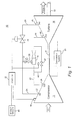
- the cooling air is typically provided by extracting air from different stages in the compressor. For example, pressurized air may be extracted from an outlet 22 at the ninth stage of the compressor and from an outlet 24 at the thirteenth stage of the compressor.
- Air conduits 26, 28, e.g., pipes, direct the pressurized air from the compressor to the turbine.
- Air conduit 26 directs the pressurized air from port 22 at the ninth compressor stage to an inlet for the cooling air to the third stage of the turbine.
- the pressure of the air extracted from the ninth compressor stage is at a pressure level appropriate for the cooling air for the turbine buckets and blades of the third turbine stage.
- a valve 30 regulates the amount of compressor air in conduit 26 and may adjust the air from fully open to fully closed and intermediate positions between the open and closed positions.
- the valve 30 adjusts the amount and pressure of the compressed air being supplied to cool the third turbine stage.
- a computer controller 32 may adjust the valve 30 based on the operating conditions of the gas turbine and an overall control algorithm of the gas turbine.
- Pressurized air extracted at port 24 from the thirteenth compressor stage is at a higher pressure than the air extracted from the ninth compressor stage.
- the air from the thirteenth compressor stage is directed via conduit 28, through an ejector 34 and to a conduit 36 that leads the cooling air to the second stage of the turbine.
- a portion of the pressurized air from the ninth compressor stage may be ducted through a conduit 37 and isolation valve 38 to the ejector 34 where the portion of air is added to the pressurized air flowing to the second turbine stage.
- the isolation valve 38 is an ON-OFF valve that is either fully open or fully closed and has no intermediate position.
- the isolation valve prevents reverse flow of compressed air from the extractor to the conduit 26 leading to the third stage of the turbine. To prevent this reverse flow, the controller 32 shuts off the isolation valve 38 during certain ambient conditions.
- the ejector 34 allows air at a lower pressure, e.g., air extracted from the ninth compressor stage, to be added to air at a higher pressure, such as the pressurized air extracted from the thirteenth stage of the compressor.
- Fixed area ejectors are known and one of which is disclosed in U.S. Patent Application Publication 2007/0125092 .
- the ejector 34 discharges air at an intermediate pressure and temperature between the pressures and temperatures of the air extracted from the thirteenth and ninth stage of the compressors.
- the pressure and temperature of the air discharged from the ejector is at a pressure suitable for cooling air to the second turbine stage.
- the controller 32 adjusts the valve 38 to either allow ninth stage compressor air to enter the ejector or to prevent such air entering the ejector.
- the controller may determine the setting of the on-off valve 38 depending on, for example, ambient conditions surrounding the gas turbine. On a cold day, for example, the controller may open valve 38 to allow ninth stage compressor air to enter the ejector and thereby increase the cooling air flow from the ejector to the second stage turbine.
- a bypass conduit 40 directs a portion of the thirteenth compressor stage around the ejector 34 and directly to the conduit 36 providing cooling air to the second stage of the turbine.
- a valve 42 regulates the air flow through the by-pass conduit and may be adjusted by the controller 32 from fully open to fully closed and at intermediate valve positions.
- the ejector 34 is configured for a specified ambient condition, such as a particular ambient pressure and temperature.
- the ejector provides a proper amount of turbine cooling air for the specified ambient condition.
- the by-pass valve 40 and associated by-pass conduit 42 provides additional turbine cooling air when needed such as when the ambient conditions are significantly different from the specified ambient condition.
- the by-pass valve may adjust to a more open position to provide additional turbine cooling air for cold day ambient conditions.
- the controller 32 adjusts valves 42 to regulate the amount of air extracted from the compressor and the cooling air provided to the turbine.
- the controller executes algorithms that determine the appropriate settings of the valves 30 and 42 based on operating conditions of the gas turbine. For example, the controller may adjust valve 42, which regulates the air in the bypass conduit 40, to maintain a predetermined ratio of the pressure of the cooling air entering the second stage of the turbine and the pressure of the air being discharged by the compressor.
- the controller 32 receives data from sensors that track the pressure and temperature of various stages in the gas turbine, the position of valves 30, 38 and 40 and other conditions of the gas turbine, such as power output.
- Pressure and temperature sensors 44 monitor the pressure and temperature at various positions within the compressor.
- Pressure and temperature sensors 46 monitor the actual ambient pressure and temperature.
- Pressure and temperature sensors 48 may monitor the pressure and temperature of the turbine cooling air provided to the second and third stages of the turbine.
- the pressure sensors in the compressor and turbine provide data used by the controller to determine the absolute pressures at the turbine second stage and compressor discharge.
- the controller 32 determines the appropriate position of the bypass valve 42.
- the bypass valve 42 may be controlled based on the ratio (S2N/CPD absolute) of the absolute pressure of the cooling air supplied to the second stage nozzle of the turbine (S2N) to absolute pressure of the air flowing at the compressor discharge (CPD).
- the S2N/CPD pressure ratio set point may be a variable dependent on the compressor discharge air pressure level, and may have a fixed set point value at gas turbine loads above a certain load level.
- the controller 32 may determine the appropriate S2N/CPD set point based on the actual compressor discharge pressure and an algorithm stored in the controller for determining the set point for the desired S2N/CPD pressure ratio. By comparing the actual pressure ratio (S2N/CPD absolute) to the S2N/CPD pressure ratio set point, the controller determines a setting for the bypass valve 42 to cause the actual pressure ratio (S2N/CPD absolute) to match the desired set point.
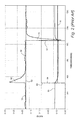
- FIGURE 2 is a chart showing conventional (prior art) control actions to maintain the S2N/CPD actual pressure ratio 50 at a desired S2N/CPD pressure ratio set point 52.
- the chart shows the values of the S2N/CPD pressure ratio 50 as a function of time in seconds.
- the chart also shows the desired S2N/CPD pressure ratio 52 as a constant value.
- the chart shows a minimum level 53 of the S2N/CPD pressure ratio which represents a condition that the S2N/CPD ratio should not reach in normal operation and, if reached, will cause the controller to take corrective actions, including possibly shutting down the gas turbine.
- the minimum level 53 is at a ratio value of 0.398.
- the chart shows the position 54 (ON/OFF) of the isolation valve (38 in Fig. 1 ) and the position 56 of the by-pass valve (42 in Fig. 1 ).
- Switching the isolation valve 38 changes the amount of turbine cooling air flowing to the turbine and, thus, causes a step-change in the S2N/CPD actual pressure ratio.
- Spikes 58 in the S2N/CPD actual pressure ratio occur when the isolation valve 38 is opened 60 and closed 62.
- the isolation valve is opened 60, the S2N/CPD actual pressure ratio spikes 58 above the desired set point 52 for the S2N/CPD.
- the controller may adjust the position of the bypass valve 42 in response to the upward spike to cause the S2N/CPD actual pressure ratio to return to the desired S2N/CPD pressure ratio set point 52.
- the isolation valve is closed 62, a downward spike occurs in the S2N/CPD actual pressure ratio.
- the controller adjusts the by-pass valve to cause S2N/CPD actual pressure ratio to return to the desired S2N/CPD pressure ratio set point. Because the isolation valve switches nearly immediately between full ON to full OFF, the resulting spike in S2N/CPD pressure ratio occurs quickly and is large. The downward spike may cause the actual S2N/CPD pressure ratio to temporarily drop below the predetermined minimum S2N/CPD pressure ratio 53. The spike may continue such that the S2N/CPD actual pressure ratio remains below the minimum level 53 for several seconds.
- the controller may determine a failure condition, e.g., cause the gas turbine to go off line or shut down, if the S2N/CPD pressure ratio remains below the minimum level 53 for more than a predetermined number of seconds.
- the controller may be unable to adjust the by-pass valve quickly enough to increase the S2N/CPD actual pressure ratio above the minimum pressure ratio 53 before the controller declares a failure condition.
- a proportional-integral (PI) control algorithm used by the controller to adjust the by-pass valve may react too slowly to compensate for the downward spike change in the actual S2N/CPD pressure ratio.
- the controller may determine that the turbine cooling air flow is inadequate and cause the turbine to be shutdown. Because there is a need to avoid, or at least minimize, shutdown conditions, there is a need to adequately compensate for spike changes in the S2N/CPD pressure ratio that can occur when the isolation valve is turned OFF or ON.
- An approach to avoid a declaration of a failure condition is to add a time delay, e.g., 30 seconds to several minutes, after the isolation valves switches before a failure condition is declared.
- the S2N/CPD may fall below the minimum pressure ratio 53.
- the delay prevents the declaration of a failure condition unless the S2N/CPD remains below the minimum pressure ratio after expiration of the time delay.
- delaying the declaration of a failure condition does not avoid the occurrence of the S2N/CPD pressure ratio falling below the predetermined minimum pressure ratio.
- the downward spike in S2N/CPD will occur when the isolation valve is turned OFF and the predetermined minimum pressure ratio will be violated.
- the spike and violation of the minimum pressure ratio may adversely affect the life of the gas turbine. While in certain circumstances it may be sufficient to include the time delay to avoid declaration of a failure condition and a resulting gas turbine shutdown, it is preferable the spike in the S2N/CPD ratio be attenuated and the ratio not fall below the minimum pressure ratio.
- FIGURE 3 is a chart of the S2N/CPD actual pressure ratio 50, the S2N/CPD set point 52, and the position 56 of the by-pass valve and the position 54 of the isolation valve.
- the S2N/CPD set point 52 does not remain constant, as is shown in Figure 2 . Rather, the S2N/CPD pressure ratio set point 52 is adjusted in an upward step 64 when the controller determines that isolation valve is to be closed.
- the step 64 is temporary and may be a few seconds, such as five seconds. After the step 64 increase, the S2N/CPD pressure ratio set point returns to its prior value.
- the controller In response to the step 64 increase to the S2N/CPD pressure ratio set point, the controller rapidly and significantly adjusts the position 56 of the bypass valve to cause the S2N/CPD actual pressure ratio to adjust to the increase in the set point value.
- the position of the bypass valve may be adjusted in a quick step 70 that causes a rapid increase 66 in the S2N/CPD actual pressure ratio.
- the rapid adjustment to the bypass valve and the increase 66 in the S2N/CPD actual pressure ratio tends to reduce the drop 68 in the S2N/CPD actual pressure ratio that occurs in response to the closing 62 isolation valve.
- the S2N/CPD actual pressure ratio does not fall below the minimum level 53 because the S2N/CPD set point was increased in a step 64 and the bypass valve was adjusted in response to the step 64 in the set point.
- the S2N/CPD actual pressure ratio is prevented from falling below the predetermined minimum level or otherwise traversing the predetermined level.
- the potential is reduced for the controller declaring a failure state due to a change in the S2N/CPD pressure ratio when the isolation valve is closed.
- the controller may apply a step increase in the S2N/CPD pressure step point when the isolation valve is opened to reduce the severity of the upward spike that would otherwise occur in the S2N/CPD actual pressure ratio.
Applications Claiming Priority (1)
| Application Number | Priority Date | Filing Date | Title |
|---|---|---|---|
| US12/120,621 US8240153B2 (en) | 2008-05-14 | 2008-05-14 | Method and system for controlling a set point for extracting air from a compressor to provide turbine cooling air in a gas turbine |
Publications (2)
| Publication Number | Publication Date |
|---|---|
| EP2119892A2 true EP2119892A2 (fr) | 2009-11-18 |
| EP2119892A3 EP2119892A3 (fr) | 2017-11-29 |
Family
ID=40897416
Family Applications (1)
| Application Number | Title | Priority Date | Filing Date |
|---|---|---|---|
| EP09159774.0A Withdrawn EP2119892A3 (fr) | 2008-05-14 | 2009-05-08 | Procédé de contrôle d'un point de réglage pour extraire l'air d'un compresseur pour fournir d'air de refroidissement de turbine dans une turbine à gaz |
Country Status (4)
| Country | Link |
|---|---|
| US (1) | US8240153B2 (fr) |
| EP (1) | EP2119892A3 (fr) |
| JP (1) | JP5039085B2 (fr) |
| CN (1) | CN101581252B (fr) |
Cited By (15)
| Publication number | Priority date | Publication date | Assignee | Title |
|---|---|---|---|---|
| ITTO20100824A1 (it) * | 2010-10-06 | 2012-04-07 | Ansaldo Energia Spa | Metodo di controllo per raffreddare uno stadio di turbina in una turbina a gas |
| GB2493835A (en) * | 2011-08-16 | 2013-02-20 | Snecma | Device for activating a passive ejector valve |
| WO2013115971A2 (fr) | 2012-01-31 | 2013-08-08 | United Technologies Corporation | Système tampon de moteur de turbine à gaz |
| WO2013163045A1 (fr) * | 2012-04-26 | 2013-10-31 | General Electric Company | Système et procédé de recirculation de gaz d'échappement destinés à être utilisés dans une pluralité de trajets d'écoulement dans un moteur à turbine à gaz |
| US9103281B2 (en) | 2010-09-10 | 2015-08-11 | Rolls-Royce Plc | Gas turbine engine havinga rotatable off-take passage in a compressor section |
| EP2809917A4 (fr) * | 2012-01-31 | 2015-08-19 | United Technologies Corp | Système tampon communicant de l'air d'alimentation de tampon à une partie d'un moteur à turbine à gaz |
| EP2390482A3 (fr) * | 2010-05-17 | 2015-09-16 | General Electric Company | Systèmes de compression d'un gaz |
| US9249729B2 (en) | 2011-12-14 | 2016-02-02 | Rolls-Royce Plc | Turbine component cooling with closed looped control of coolant flow |
| US9255492B2 (en) | 2011-12-14 | 2016-02-09 | Rolls-Royce Plc | Gas turbine engine having a multi-variable closed loop controller for regulating tip clearance |
| RU2617038C2 (ru) * | 2012-01-27 | 2017-04-19 | Дженерал Электрик Компани | Система очистки канала турбомашины, турбомашина и способ фильтрации воздушного потока, проходящего от компрессора к турбине турбомашины |
| EP2587028A3 (fr) * | 2011-10-31 | 2017-07-19 | General Electric Company | Système de commande de jeu actif et procédé pour un moteur de turbine à gaz |
| US9784185B2 (en) | 2012-04-26 | 2017-10-10 | General Electric Company | System and method for cooling a gas turbine with an exhaust gas provided by the gas turbine |
| EP3406884A1 (fr) * | 2017-05-22 | 2018-11-28 | United Technologies Corporation | Système de sécurité de flux de purge |
| US10273880B2 (en) | 2012-04-26 | 2019-04-30 | General Electric Company | System and method of recirculating exhaust gas for use in a plurality of flow paths in a gas turbine engine |
| EP3667044A1 (fr) * | 2018-12-10 | 2020-06-17 | Bell Helicopter Textron Inc. | Système et procédé de la modulation sélective de l'écoulement d'air de purge utilisé pour le refroidissement d'étage de turbine haute pression dans un moteur à turbine à gaz |
Families Citing this family (107)
| Publication number | Priority date | Publication date | Assignee | Title |
|---|---|---|---|---|
| US20030097872A1 (en) * | 2001-11-29 | 2003-05-29 | Granitz Charles Robert | System for reducing oil consumption in gas turbine engines |
| MY153097A (en) | 2008-03-28 | 2014-12-31 | Exxonmobil Upstream Res Co | Low emission power generation and hydrocarbon recovery systems and methods |
| MY156350A (en) | 2008-03-28 | 2016-02-15 | Exxonmobil Upstream Res Co | Low emission power generation and hydrocarbon recovery systems and methods |
| ES2370949T3 (es) * | 2008-07-16 | 2011-12-26 | Siemens Aktiengesellschaft | Válvula controlada por fluído para una turbina de gas y para una cámara de combustión. |
| EA026915B1 (ru) | 2008-10-14 | 2017-05-31 | Эксонмобил Апстрим Рисерч Компани | Способы и системы для регулирования продуктов горения |
| US8267122B2 (en) * | 2009-06-30 | 2012-09-18 | Ge Aviation Systems Llc | Method and systems for bleed air supply |
| IT1395820B1 (it) * | 2009-09-25 | 2012-10-26 | Nuovo Pignone Spa | Sistema di raffreddamento per una turbina a gas e relativo metodo di funzionamento |
| US8337139B2 (en) * | 2009-11-10 | 2012-12-25 | General Electric Company | Method and system for reducing the impact on the performance of a turbomachine operating an extraction system |
| SG10201407421UA (en) | 2009-11-12 | 2014-12-30 | Exxonmobil Upstream Res Co | Low emission power generation and hydrocarbon recovery systems and methods |
| JP4958967B2 (ja) * | 2009-12-15 | 2012-06-20 | 川崎重工業株式会社 | 換気構造を改良したガスタービンエンジン |
| MY164051A (en) | 2010-07-02 | 2017-11-15 | Exxonmobil Upstream Res Co | Low emission triple-cycle power generation systems and methods |
| SG186158A1 (en) | 2010-07-02 | 2013-01-30 | Exxonmobil Upstream Res Co | Low emission power generation systems and methods |
| CN102959202B (zh) | 2010-07-02 | 2016-08-03 | 埃克森美孚上游研究公司 | 集成系统、发电的方法和联合循环发电系统 |
| CN102959203B (zh) | 2010-07-02 | 2018-10-09 | 埃克森美孚上游研究公司 | 通过排气再循环的浓缩空气的化学计量燃烧 |
| US20120167587A1 (en) * | 2010-12-30 | 2012-07-05 | Robert Earl Clark | Gas turbine engine with bleed air system |
| TWI593872B (zh) | 2011-03-22 | 2017-08-01 | 艾克頌美孚上游研究公司 | 整合系統及產生動力之方法 |
| TWI564474B (zh) | 2011-03-22 | 2017-01-01 | 艾克頌美孚上游研究公司 | 於渦輪系統中控制化學計量燃燒的整合系統和使用彼之產生動力的方法 |
| TWI563165B (en) | 2011-03-22 | 2016-12-21 | Exxonmobil Upstream Res Co | Power generation system and method for generating power |
| TWI563166B (en) | 2011-03-22 | 2016-12-21 | Exxonmobil Upstream Res Co | Integrated generation systems and methods for generating power |
| EP2562369B1 (fr) * | 2011-08-22 | 2015-01-14 | Alstom Technology Ltd | Méthode pour opérer une turbine à gaz et turbine à gaz pour exécuter la méthode |
| US9260974B2 (en) * | 2011-12-16 | 2016-02-16 | General Electric Company | System and method for active clearance control |
| CN104428490B (zh) | 2011-12-20 | 2018-06-05 | 埃克森美孚上游研究公司 | 提高的煤层甲烷生产 |
| US9169782B2 (en) * | 2012-01-04 | 2015-10-27 | General Electric Company | Turbine to operate at part-load |
| US9322333B2 (en) * | 2012-01-06 | 2016-04-26 | General Electric Company | System and method for determining a cooling flow parameter downstream from a gas turbine combustor |
| US9353682B2 (en) | 2012-04-12 | 2016-05-31 | General Electric Company | Methods, systems and apparatus relating to combustion turbine power plants with exhaust gas recirculation |
| KR101933585B1 (ko) * | 2012-07-25 | 2018-12-28 | 한화에어로스페이스 주식회사 | 가스 터빈 장치 |
| US9003762B2 (en) * | 2012-10-02 | 2015-04-14 | General Electric Company | Turbine exhaust plume mitigation system |
| US10100741B2 (en) | 2012-11-02 | 2018-10-16 | General Electric Company | System and method for diffusion combustion with oxidant-diluent mixing in a stoichiometric exhaust gas recirculation gas turbine system |
| US9708977B2 (en) | 2012-12-28 | 2017-07-18 | General Electric Company | System and method for reheat in gas turbine with exhaust gas recirculation |
| US9631815B2 (en) | 2012-12-28 | 2017-04-25 | General Electric Company | System and method for a turbine combustor |
| US9803865B2 (en) | 2012-12-28 | 2017-10-31 | General Electric Company | System and method for a turbine combustor |
| US9611756B2 (en) | 2012-11-02 | 2017-04-04 | General Electric Company | System and method for protecting components in a gas turbine engine with exhaust gas recirculation |
| US10107495B2 (en) | 2012-11-02 | 2018-10-23 | General Electric Company | Gas turbine combustor control system for stoichiometric combustion in the presence of a diluent |
| US9599070B2 (en) | 2012-11-02 | 2017-03-21 | General Electric Company | System and method for oxidant compression in a stoichiometric exhaust gas recirculation gas turbine system |
| US10215412B2 (en) | 2012-11-02 | 2019-02-26 | General Electric Company | System and method for load control with diffusion combustion in a stoichiometric exhaust gas recirculation gas turbine system |
| US9574496B2 (en) | 2012-12-28 | 2017-02-21 | General Electric Company | System and method for a turbine combustor |
| US9869279B2 (en) | 2012-11-02 | 2018-01-16 | General Electric Company | System and method for a multi-wall turbine combustor |
| US9175783B2 (en) * | 2012-11-16 | 2015-11-03 | Ford Global Technologies, Llc | Vacuum-actuated wastegate |
| US9562475B2 (en) * | 2012-12-19 | 2017-02-07 | Siemens Aktiengesellschaft | Vane carrier temperature control system in a gas turbine engine |
| US10208677B2 (en) | 2012-12-31 | 2019-02-19 | General Electric Company | Gas turbine load control system |
| US9581081B2 (en) | 2013-01-13 | 2017-02-28 | General Electric Company | System and method for protecting components in a gas turbine engine with exhaust gas recirculation |
| ITMI20130089A1 (it) * | 2013-01-23 | 2014-07-24 | Ansaldo Energia Spa | Impianto a turbina a gas per la produzione di energia elettrica e metodo per operare detto impianto |
| US9512759B2 (en) | 2013-02-06 | 2016-12-06 | General Electric Company | System and method for catalyst heat utilization for gas turbine with exhaust gas recirculation |
| TW201502356A (zh) | 2013-02-21 | 2015-01-16 | Exxonmobil Upstream Res Co | 氣渦輪機排氣中氧之減少 |
| US9938861B2 (en) | 2013-02-21 | 2018-04-10 | Exxonmobil Upstream Research Company | Fuel combusting method |
| US10221762B2 (en) | 2013-02-28 | 2019-03-05 | General Electric Company | System and method for a turbine combustor |
| EP2964735A1 (fr) | 2013-03-08 | 2016-01-13 | Exxonmobil Upstream Research Company | Production d'énergie et récupération de méthane à partir d'hydrates de méthane |
| US9618261B2 (en) | 2013-03-08 | 2017-04-11 | Exxonmobil Upstream Research Company | Power generation and LNG production |
| US20140250945A1 (en) | 2013-03-08 | 2014-09-11 | Richard A. Huntington | Carbon Dioxide Recovery |
| TW201500635A (zh) | 2013-03-08 | 2015-01-01 | Exxonmobil Upstream Res Co | 處理廢氣以供用於提高油回收 |
| US9482236B2 (en) | 2013-03-13 | 2016-11-01 | Rolls-Royce Corporation | Modulated cooling flow scheduling for both SFC improvement and stall margin increase |
| US9447702B2 (en) | 2013-06-21 | 2016-09-20 | Sankar K. Mohan | Cooling system and cooling method for use with closed loop systems |
| US9631542B2 (en) | 2013-06-28 | 2017-04-25 | General Electric Company | System and method for exhausting combustion gases from gas turbine engines |
| US9835089B2 (en) | 2013-06-28 | 2017-12-05 | General Electric Company | System and method for a fuel nozzle |
| TWI654368B (zh) | 2013-06-28 | 2019-03-21 | 美商艾克頌美孚上游研究公司 | 用於控制在廢氣再循環氣渦輪機系統中的廢氣流之系統、方法與媒體 |
| US9617914B2 (en) | 2013-06-28 | 2017-04-11 | General Electric Company | Systems and methods for monitoring gas turbine systems having exhaust gas recirculation |
| US10227927B2 (en) | 2013-07-17 | 2019-03-12 | United Technologies Corporation | Supply duct for cooling air from gas turbine compressor |
| US9903588B2 (en) | 2013-07-30 | 2018-02-27 | General Electric Company | System and method for barrier in passage of combustor of gas turbine engine with exhaust gas recirculation |
| US9587510B2 (en) | 2013-07-30 | 2017-03-07 | General Electric Company | System and method for a gas turbine engine sensor |
| US9951658B2 (en) | 2013-07-31 | 2018-04-24 | General Electric Company | System and method for an oxidant heating system |
| EP2857656A1 (fr) * | 2013-10-01 | 2015-04-08 | Alstom Technology Ltd | Turbine à gaz avec système de refroidissement d'air de refroidissement et procédé de fonctionnement d'une turbine à gaz à faible charge partielle |
| US9752458B2 (en) | 2013-12-04 | 2017-09-05 | General Electric Company | System and method for a gas turbine engine |
| US10030588B2 (en) | 2013-12-04 | 2018-07-24 | General Electric Company | Gas turbine combustor diagnostic system and method |
| CN103697281A (zh) * | 2013-12-27 | 2014-04-02 | 北京华清燃气轮机与煤气化联合循环工程技术有限公司 | 燃气轮机低压引气管路和高压引气管路之间的节流结构 |
| US10227920B2 (en) | 2014-01-15 | 2019-03-12 | General Electric Company | Gas turbine oxidant separation system |
| US9863267B2 (en) | 2014-01-21 | 2018-01-09 | General Electric Company | System and method of control for a gas turbine engine |
| US9915200B2 (en) | 2014-01-21 | 2018-03-13 | General Electric Company | System and method for controlling the combustion process in a gas turbine operating with exhaust gas recirculation |
| US10079564B2 (en) | 2014-01-27 | 2018-09-18 | General Electric Company | System and method for a stoichiometric exhaust gas recirculation gas turbine system |
| US9580180B2 (en) | 2014-03-07 | 2017-02-28 | Honeywell International Inc. | Low-pressure bleed air aircraft environmental control system |
| US9644542B2 (en) * | 2014-05-12 | 2017-05-09 | General Electric Company | Turbine cooling system using an enhanced compressor air flow |
| US10047633B2 (en) | 2014-05-16 | 2018-08-14 | General Electric Company | Bearing housing |
| CN106460677B (zh) * | 2014-05-21 | 2018-09-18 | 西门子能源公司 | 在燃气涡轮机中将冷却流动从压缩机提供到涡轮机的方法 |
| EP2957746B1 (fr) * | 2014-06-17 | 2021-04-28 | Raytheon Technologies Corporation | Refroidissement de turbine haute pression |
| US9885290B2 (en) | 2014-06-30 | 2018-02-06 | General Electric Company | Erosion suppression system and method in an exhaust gas recirculation gas turbine system |
| US10060359B2 (en) | 2014-06-30 | 2018-08-28 | General Electric Company | Method and system for combustion control for gas turbine system with exhaust gas recirculation |
| US10655542B2 (en) | 2014-06-30 | 2020-05-19 | General Electric Company | Method and system for startup of gas turbine system drive trains with exhaust gas recirculation |
| US10767562B2 (en) * | 2014-12-10 | 2020-09-08 | Pratt & Whitney Canada Corp. | Modulated cooled P3 air for impeller |
| US9869247B2 (en) | 2014-12-31 | 2018-01-16 | General Electric Company | Systems and methods of estimating a combustion equivalence ratio in a gas turbine with exhaust gas recirculation |
| US9819292B2 (en) | 2014-12-31 | 2017-11-14 | General Electric Company | Systems and methods to respond to grid overfrequency events for a stoichiometric exhaust recirculation gas turbine |
| US10788212B2 (en) | 2015-01-12 | 2020-09-29 | General Electric Company | System and method for an oxidant passageway in a gas turbine system with exhaust gas recirculation |
| US10316746B2 (en) | 2015-02-04 | 2019-06-11 | General Electric Company | Turbine system with exhaust gas recirculation, separation and extraction |
| US10253690B2 (en) | 2015-02-04 | 2019-04-09 | General Electric Company | Turbine system with exhaust gas recirculation, separation and extraction |
| US10094566B2 (en) | 2015-02-04 | 2018-10-09 | General Electric Company | Systems and methods for high volumetric oxidant flow in gas turbine engine with exhaust gas recirculation |
| US10267270B2 (en) | 2015-02-06 | 2019-04-23 | General Electric Company | Systems and methods for carbon black production with a gas turbine engine having exhaust gas recirculation |
| US10145269B2 (en) | 2015-03-04 | 2018-12-04 | General Electric Company | System and method for cooling discharge flow |
| US10480792B2 (en) | 2015-03-06 | 2019-11-19 | General Electric Company | Fuel staging in a gas turbine engine |
| US9863285B2 (en) | 2015-03-19 | 2018-01-09 | General Electric Company | Power generation system having compressor creating excess gas flow for supplemental gas turbine system |
| US20160273401A1 (en) * | 2015-03-19 | 2016-09-22 | General Electric Company | Power generation system having compressor creating excess air flow and eductor for process air demand |
| US10024197B2 (en) | 2015-03-19 | 2018-07-17 | General Electric Company | Power generation system having compressor creating excess air flow and turbo-expander using same |
| JP5897180B2 (ja) * | 2015-04-03 | 2016-03-30 | 三菱日立パワーシステムズ株式会社 | ガスタービン |
| US10830148B2 (en) | 2015-04-24 | 2020-11-10 | Raytheon Technologies Corporation | Intercooled cooling air with dual pass heat exchanger |
| US9850819B2 (en) * | 2015-04-24 | 2017-12-26 | United Technologies Corporation | Intercooled cooling air with dual pass heat exchanger |
| KR101790146B1 (ko) * | 2015-07-14 | 2017-10-25 | 두산중공업 주식회사 | 외부 케이싱으로 우회하는 냉각공기 공급유로가 마련된 냉각시스템을 포함하는 가스터빈. |
| US10502137B2 (en) * | 2015-10-19 | 2019-12-10 | General Electric Company | Gas turbine with a valve cooling system |
| US10480342B2 (en) * | 2016-01-19 | 2019-11-19 | Rolls-Royce Corporation | Gas turbine engine with health monitoring system |
| JP6801968B2 (ja) * | 2016-02-15 | 2020-12-16 | 三菱パワー株式会社 | ガスタービンの制御装置および制御方法、並びにガスタービン |
| GB2547674A (en) * | 2016-02-25 | 2017-08-30 | Rolls Royce Plc | Gas turbine engine |
| CN105736080B (zh) * | 2016-04-29 | 2017-12-05 | 华电郑州机械设计研究院有限公司 | 一种新型火电厂小汽轮机轴封抽汽系统 |
| US20180057171A1 (en) * | 2016-08-23 | 2018-03-01 | Ge Aviation Systems, Llc | Advanced method and aircraft for pre-cooling an environmental control system using a three wheel turbo-machine |
| US10731568B2 (en) | 2016-11-23 | 2020-08-04 | General Electric Company | Systems and methods for reducing airflow imbalances in turbines |
| GB201619960D0 (en) | 2016-11-25 | 2017-01-11 | Rolls Royce Plc | Gas turbine engine |
| US10473037B2 (en) | 2017-05-22 | 2019-11-12 | United Technologies Corporation | Passively-driven bleed source switching |
| US11578668B2 (en) | 2017-05-30 | 2023-02-14 | Raytheon Technologies Corporation | Gas turbine engine control based on characteristic of cooled air |
| FR3072414B1 (fr) * | 2017-10-16 | 2019-11-01 | Safran Aircraft Engines | Dispositif et procede de refroidissement d'une turbine basse pression dans une turbomachine |
| DE102018125748A1 (de) * | 2018-10-17 | 2020-04-23 | Rolls-Royce Deutschland Ltd & Co Kg | Ausfallerkennungssystem eines Kühlluftzufuhrsystems und Ausfallerkennungsverfahren für ein Kühlluftzufuhrsystemeiner Hochdruckturbine |
| US11738833B1 (en) | 2020-03-31 | 2023-08-29 | Bombardier Recreational Products Inc. | Fender system for a watercraft |
| US11828223B2 (en) * | 2021-05-28 | 2023-11-28 | Honeywell International Inc. | Variable jet pump |
Citations (1)
| Publication number | Priority date | Publication date | Assignee | Title |
|---|---|---|---|---|
| US20070125092A1 (en) | 2005-12-07 | 2007-06-07 | General Electric Company | Variable motive nozzle ejector for use with turbine engines |
Family Cites Families (8)
| Publication number | Priority date | Publication date | Assignee | Title |
|---|---|---|---|---|
| ID29539A (id) | 1999-01-20 | 2001-09-06 | Mykrolis Corp | Pengontrol aliran |
| US6550253B2 (en) * | 2001-09-12 | 2003-04-22 | General Electric Company | Apparatus and methods for controlling flow in turbomachinery |
| US6523346B1 (en) * | 2001-11-02 | 2003-02-25 | Alstom (Switzerland) Ltd | Process for controlling the cooling air mass flow of a gas turbine set |
| GB0224625D0 (en) * | 2002-10-23 | 2002-12-04 | Honeywell Normalair Garrett | Method of balancing the supply of bleed air from a plurality of engines |
| US7536865B2 (en) * | 2005-02-09 | 2009-05-26 | Honeywell International Inc. | Method and system for balancing bleed flows from gas turbine engines |
| US20070137213A1 (en) * | 2005-12-19 | 2007-06-21 | General Electric Company | Turbine wheelspace temperature control |
| US8136361B2 (en) * | 2006-05-04 | 2012-03-20 | General Electric Company | Methods and apparatus for assembling a low noise ejector motive nozzle |
| US7328098B1 (en) * | 2007-04-03 | 2008-02-05 | United Technologies Corporation | Determining bleed valve failures in gas turbine engines |
-
2008
- 2008-05-14 US US12/120,621 patent/US8240153B2/en active Active
-
2009
- 2009-05-08 EP EP09159774.0A patent/EP2119892A3/fr not_active Withdrawn
- 2009-05-12 CN CN2009101389251A patent/CN101581252B/zh not_active Expired - Fee Related
- 2009-05-12 JP JP2009115096A patent/JP5039085B2/ja not_active Expired - Fee Related
Patent Citations (1)
| Publication number | Priority date | Publication date | Assignee | Title |
|---|---|---|---|---|
| US20070125092A1 (en) | 2005-12-07 | 2007-06-07 | General Electric Company | Variable motive nozzle ejector for use with turbine engines |
Cited By (30)
| Publication number | Priority date | Publication date | Assignee | Title |
|---|---|---|---|---|
| EP2390482A3 (fr) * | 2010-05-17 | 2015-09-16 | General Electric Company | Systèmes de compression d'un gaz |
| US9103281B2 (en) | 2010-09-10 | 2015-08-11 | Rolls-Royce Plc | Gas turbine engine havinga rotatable off-take passage in a compressor section |
| US8881532B2 (en) | 2010-10-06 | 2014-11-11 | Ansaldo Energia S.P.A. | Control method for cooling a turbine stage in a gas turbine |
| EP2439390A1 (fr) * | 2010-10-06 | 2012-04-11 | Ansaldo Energia S.p.A. | Procédé de contrôle pour refroidir un étage de turbine dans une turbine à gaz |
| JP2012082829A (ja) * | 2010-10-06 | 2012-04-26 | Ansaldo Energia Spa | ガスタービンのタービンステージの冷却の制御方法 |
| ITTO20100824A1 (it) * | 2010-10-06 | 2012-04-07 | Ansaldo Energia Spa | Metodo di controllo per raffreddare uno stadio di turbina in una turbina a gas |
| GB2493835A (en) * | 2011-08-16 | 2013-02-20 | Snecma | Device for activating a passive ejector valve |
| GB2493835B (en) * | 2011-08-16 | 2014-01-29 | Snecma | Device for activating a passive ejector valve |
| US9212757B2 (en) | 2011-08-16 | 2015-12-15 | Snecma | Device for activating a passive ejector valve for pressurising a turbojet engine chamber for an aircraft |
| EP2587028A3 (fr) * | 2011-10-31 | 2017-07-19 | General Electric Company | Système de commande de jeu actif et procédé pour un moteur de turbine à gaz |
| US9255492B2 (en) | 2011-12-14 | 2016-02-09 | Rolls-Royce Plc | Gas turbine engine having a multi-variable closed loop controller for regulating tip clearance |
| US9249729B2 (en) | 2011-12-14 | 2016-02-02 | Rolls-Royce Plc | Turbine component cooling with closed looped control of coolant flow |
| RU2617038C2 (ru) * | 2012-01-27 | 2017-04-19 | Дженерал Электрик Компани | Система очистки канала турбомашины, турбомашина и способ фильтрации воздушного потока, проходящего от компрессора к турбине турбомашины |
| US11499476B2 (en) | 2012-01-31 | 2022-11-15 | Raytheon Technologies Corporation | Gas turbine engine buffer system |
| EP2809917A4 (fr) * | 2012-01-31 | 2015-08-19 | United Technologies Corp | Système tampon communicant de l'air d'alimentation de tampon à une partie d'un moteur à turbine à gaz |
| EP2809906A4 (fr) * | 2012-01-31 | 2016-06-29 | United Technologies Corp | Système tampon de moteur de turbine à gaz |
| US10487734B2 (en) | 2012-01-31 | 2019-11-26 | United Technologies Corporation | Gas turbine engine buffer system |
| WO2013115971A2 (fr) | 2012-01-31 | 2013-08-08 | United Technologies Corporation | Système tampon de moteur de turbine à gaz |
| US11098644B2 (en) | 2012-01-31 | 2021-08-24 | Raytheon Technologies Corporation | Gas turbine engine buffer system |
| EP3309372A1 (fr) * | 2012-01-31 | 2018-04-18 | United Technologies Corporation | Système de tampon communiquant de l'air d'alimentation tampon à une partie d'un moteur à turbine à gaz |
| EP3848567A1 (fr) * | 2012-01-31 | 2021-07-14 | Raytheon Technologies Corporation | Système tampon de moteur de turbine à gaz |
| US10724431B2 (en) | 2012-01-31 | 2020-07-28 | Raytheon Technologies Corporation | Buffer system that communicates buffer supply air to one or more portions of a gas turbine engine |
| AU2013252625B2 (en) * | 2012-04-26 | 2016-04-28 | Exxonmobil Upstream Research Company | System and method of recirculating exhaust gas for use in a plurality of flow paths in a gas turbine engine |
| US10273880B2 (en) | 2012-04-26 | 2019-04-30 | General Electric Company | System and method of recirculating exhaust gas for use in a plurality of flow paths in a gas turbine engine |
| US9784185B2 (en) | 2012-04-26 | 2017-10-10 | General Electric Company | System and method for cooling a gas turbine with an exhaust gas provided by the gas turbine |
| WO2013163045A1 (fr) * | 2012-04-26 | 2013-10-31 | General Electric Company | Système et procédé de recirculation de gaz d'échappement destinés à être utilisés dans une pluralité de trajets d'écoulement dans un moteur à turbine à gaz |
| EP3406884A1 (fr) * | 2017-05-22 | 2018-11-28 | United Technologies Corporation | Système de sécurité de flux de purge |
| US11739697B2 (en) | 2017-05-22 | 2023-08-29 | Raytheon Technologies Corporation | Bleed flow safety system |
| EP3667044A1 (fr) * | 2018-12-10 | 2020-06-17 | Bell Helicopter Textron Inc. | Système et procédé de la modulation sélective de l'écoulement d'air de purge utilisé pour le refroidissement d'étage de turbine haute pression dans un moteur à turbine à gaz |
| US11047313B2 (en) | 2018-12-10 | 2021-06-29 | Bell Helicopter Textron Inc. | System and method for selectively modulating the flow of bleed air used for high pressure turbine stage cooling in a power turbine engine |
Also Published As
| Publication number | Publication date |
|---|---|
| US8240153B2 (en) | 2012-08-14 |
| JP5039085B2 (ja) | 2012-10-03 |
| CN101581252A (zh) | 2009-11-18 |
| CN101581252B (zh) | 2013-12-04 |
| EP2119892A3 (fr) | 2017-11-29 |
| JP2009275702A (ja) | 2009-11-26 |
| US20120117977A1 (en) | 2012-05-17 |
Similar Documents
| Publication | Publication Date | Title |
|---|---|---|
| US8240153B2 (en) | Method and system for controlling a set point for extracting air from a compressor to provide turbine cooling air in a gas turbine | |
| EP2871349B1 (fr) | Procédé d'opération d'un système pneumatique pour un aéronef | |
| US6385958B2 (en) | Method for pressure modulation of turbine sidewall cavities | |
| US6226974B1 (en) | Method of operation of industrial gas turbine for optimal performance | |
| CA2451049C (fr) | Controle de la temperature de combustion d'une turbine a gaz par prelevement d'air sur compresseur | |
| EP1770331B1 (fr) | Procédé pour contrôler la partition de l'air de dérivation vers la chambre de combustion de turbine | |
| US6463730B1 (en) | Valve control logic for gas turbine recuperator | |
| CN103541815B (zh) | 用于燃气涡轮发动机喘振控制的方法和布置 | |
| US20070137213A1 (en) | Turbine wheelspace temperature control | |
| CN113748268B (zh) | 压缩系统和控制压缩系统的方法 | |
| US9611752B2 (en) | Compressor start bleed system for a turbine system and method of controlling a compressor start bleed system | |
| GB2524582A (en) | Combined cycle gas turbine plant | |
| JP4163131B2 (ja) | 二軸式ガスタービン発電システム及びその停止方法 | |
| JP5897180B2 (ja) | ガスタービン | |
| JPH11280408A (ja) | 蒸気タービンの制御方法 | |
| CN113217197A (zh) | 用于运行发电厂的方法以及发电厂 | |
| US10167742B2 (en) | Steam cycle, and method for operating a steam cycle | |
| WO2020230485A1 (fr) | Dispositif et procédé d'alimentation en gaz combustible |
Legal Events
| Date | Code | Title | Description |
|---|---|---|---|
| PUAI | Public reference made under article 153(3) epc to a published international application that has entered the european phase |
Free format text: ORIGINAL CODE: 0009012 |
|
| AK | Designated contracting states |
Kind code of ref document: A2 Designated state(s): AT BE BG CH CY CZ DE DK EE ES FI FR GB GR HR HU IE IS IT LI LT LU LV MC MK MT NL NO PL PT RO SE SI SK TR |
|
| PUAL | Search report despatched |
Free format text: ORIGINAL CODE: 0009013 |
|
| AK | Designated contracting states |
Kind code of ref document: A3 Designated state(s): AT BE BG CH CY CZ DE DK EE ES FI FR GB GR HR HU IE IS IT LI LT LU LV MC MK MT NL NO PL PT RO SE SI SK TR |
|
| AX | Request for extension of the european patent |
Extension state: AL BA RS |
|
| RIC1 | Information provided on ipc code assigned before grant |
Ipc: F02C 7/18 20060101ALI20171026BHEP Ipc: F02C 9/18 20060101ALI20171026BHEP Ipc: F02C 6/08 20060101AFI20171026BHEP |
|
| 17P | Request for examination filed |
Effective date: 20180529 |
|
| RBV | Designated contracting states (corrected) |
Designated state(s): AT BE BG CH CY CZ DE DK EE ES FI FR GB GR HR HU IE IS IT LI LT LU LV MC MK MT NL NO PL PT RO SE SI SK TR |
|
| GRAP | Despatch of communication of intention to grant a patent |
Free format text: ORIGINAL CODE: EPIDOSNIGR1 |
|
| INTG | Intention to grant announced |
Effective date: 20180824 |
|
| RIN1 | Information on inventor provided before grant (corrected) |
Inventor name: TRUESDALE, ALAN MEJER Inventor name: WHALING, KENNETH NEIL Inventor name: CHILDERS, PRISCILLA Inventor name: DISCH, MARK Inventor name: BALL, DAVID WESLEY, JR. Inventor name: NEWTON, CURTIS, III |
|
| STAA | Information on the status of an ep patent application or granted ep patent |
Free format text: STATUS: THE APPLICATION IS DEEMED TO BE WITHDRAWN |
|
| 18D | Application deemed to be withdrawn |
Effective date: 20190104 |