EP2119679A1 - Procédé de traitement d'une strate - Google Patents
Procédé de traitement d'une strate Download PDFInfo
- Publication number
- EP2119679A1 EP2119679A1 EP08405137A EP08405137A EP2119679A1 EP 2119679 A1 EP2119679 A1 EP 2119679A1 EP 08405137 A EP08405137 A EP 08405137A EP 08405137 A EP08405137 A EP 08405137A EP 2119679 A1 EP2119679 A1 EP 2119679A1
- Authority
- EP
- European Patent Office
- Prior art keywords
- laminate
- station
- processing
- distance
- fixed plate
- Prior art date
- Legal status (The legal status is an assumption and is not a legal conclusion. Google has not performed a legal analysis and makes no representation as to the accuracy of the status listed.)
- Withdrawn
Links
- 238000012545 processing Methods 0.000 title claims abstract description 42
- 238000000034 method Methods 0.000 title claims abstract description 35
- 239000011521 glass Substances 0.000 claims abstract description 49
- 238000003475 lamination Methods 0.000 claims abstract description 15
- 238000005259 measurement Methods 0.000 claims abstract description 7
- 238000005520 cutting process Methods 0.000 claims description 63
- 238000010030 laminating Methods 0.000 claims description 13
- 239000007787 solid Substances 0.000 claims description 12
- 238000009434 installation Methods 0.000 claims description 6
- 238000012937 correction Methods 0.000 claims description 4
- 239000003550 marker Substances 0.000 claims description 4
- 238000003754 machining Methods 0.000 claims 1
- 230000008569 process Effects 0.000 abstract description 8
- 239000011159 matrix material Substances 0.000 description 8
- 239000005038 ethylene vinyl acetate Substances 0.000 description 7
- 229920003023 plastic Polymers 0.000 description 7
- 238000004519 manufacturing process Methods 0.000 description 6
- 230000005855 radiation Effects 0.000 description 6
- DQXBYHZEEUGOBF-UHFFFAOYSA-N but-3-enoic acid;ethene Chemical compound C=C.OC(=O)CC=C DQXBYHZEEUGOBF-UHFFFAOYSA-N 0.000 description 5
- 239000004033 plastic Substances 0.000 description 5
- 229920001200 poly(ethylene-vinyl acetate) Polymers 0.000 description 5
- 238000000926 separation method Methods 0.000 description 5
- 238000001514 detection method Methods 0.000 description 4
- 230000002093 peripheral effect Effects 0.000 description 4
- FOIXSVOLVBLSDH-UHFFFAOYSA-N Silver ion Chemical compound [Ag+] FOIXSVOLVBLSDH-UHFFFAOYSA-N 0.000 description 3
- 230000006378 damage Effects 0.000 description 3
- 238000005516 engineering process Methods 0.000 description 3
- 239000005340 laminated glass Substances 0.000 description 3
- 239000002985 plastic film Substances 0.000 description 3
- 229920006255 plastic film Polymers 0.000 description 3
- 239000000758 substrate Substances 0.000 description 3
- 238000010586 diagram Methods 0.000 description 2
- 238000006073 displacement reaction Methods 0.000 description 2
- 239000005357 flat glass Substances 0.000 description 2
- 230000001939 inductive effect Effects 0.000 description 2
- 229920000728 polyester Polymers 0.000 description 2
- XUIMIQQOPSSXEZ-UHFFFAOYSA-N Silicon Chemical compound [Si] XUIMIQQOPSSXEZ-UHFFFAOYSA-N 0.000 description 1
- 208000027418 Wounds and injury Diseases 0.000 description 1
- 238000013459 approach Methods 0.000 description 1
- 230000008901 benefit Effects 0.000 description 1
- 238000004140 cleaning Methods 0.000 description 1
- 230000009849 deactivation Effects 0.000 description 1
- 230000000694 effects Effects 0.000 description 1
- 239000011888 foil Substances 0.000 description 1
- 239000012535 impurity Substances 0.000 description 1
- 208000014674 injury Diseases 0.000 description 1
- 238000007641 inkjet printing Methods 0.000 description 1
- 238000005342 ion exchange Methods 0.000 description 1
- 230000001788 irregular Effects 0.000 description 1
- 239000000463 material Substances 0.000 description 1
- 229910052751 metal Inorganic materials 0.000 description 1
- 239000002184 metal Substances 0.000 description 1
- 238000012986 modification Methods 0.000 description 1
- 230000004048 modification Effects 0.000 description 1
- 229920002620 polyvinyl fluoride Polymers 0.000 description 1
- 239000005336 safety glass Substances 0.000 description 1
- 238000007790 scraping Methods 0.000 description 1
- 229910052710 silicon Inorganic materials 0.000 description 1
- 239000010703 silicon Substances 0.000 description 1
- 229910052709 silver Inorganic materials 0.000 description 1
- 239000004332 silver Substances 0.000 description 1
- -1 silver ions Chemical class 0.000 description 1
- 239000000779 smoke Substances 0.000 description 1
- 239000000126 substance Substances 0.000 description 1
- 230000008961 swelling Effects 0.000 description 1
- 239000005341 toughened glass Substances 0.000 description 1
- 230000007704 transition Effects 0.000 description 1
- 238000009966 trimming Methods 0.000 description 1
Images

Classifications
-
- C—CHEMISTRY; METALLURGY
- C03—GLASS; MINERAL OR SLAG WOOL
- C03B—MANUFACTURE, SHAPING, OR SUPPLEMENTARY PROCESSES
- C03B33/00—Severing cooled glass
- C03B33/07—Cutting armoured, multi-layered, coated or laminated, glass products
- C03B33/074—Glass products comprising an outer layer or surface coating of non-glass material
-
- B—PERFORMING OPERATIONS; TRANSPORTING
- B26—HAND CUTTING TOOLS; CUTTING; SEVERING
- B26D—CUTTING; DETAILS COMMON TO MACHINES FOR PERFORATING, PUNCHING, CUTTING-OUT, STAMPING-OUT OR SEVERING
- B26D1/00—Cutting through work characterised by the nature or movement of the cutting member or particular materials not otherwise provided for; Apparatus or machines therefor; Cutting members therefor
- B26D1/01—Cutting through work characterised by the nature or movement of the cutting member or particular materials not otherwise provided for; Apparatus or machines therefor; Cutting members therefor involving a cutting member which does not travel with the work
- B26D1/04—Cutting through work characterised by the nature or movement of the cutting member or particular materials not otherwise provided for; Apparatus or machines therefor; Cutting members therefor involving a cutting member which does not travel with the work having a linearly-movable cutting member
- B26D1/045—Cutting through work characterised by the nature or movement of the cutting member or particular materials not otherwise provided for; Apparatus or machines therefor; Cutting members therefor involving a cutting member which does not travel with the work having a linearly-movable cutting member for thin material, e.g. for sheets, strips or the like
-
- B—PERFORMING OPERATIONS; TRANSPORTING
- B26—HAND CUTTING TOOLS; CUTTING; SEVERING
- B26D—CUTTING; DETAILS COMMON TO MACHINES FOR PERFORATING, PUNCHING, CUTTING-OUT, STAMPING-OUT OR SEVERING
- B26D7/00—Details of apparatus for cutting, cutting-out, stamping-out, punching, perforating, or severing by means other than cutting
- B26D7/01—Means for holding or positioning work
-
- B—PERFORMING OPERATIONS; TRANSPORTING
- B32—LAYERED PRODUCTS
- B32B—LAYERED PRODUCTS, i.e. PRODUCTS BUILT-UP OF STRATA OF FLAT OR NON-FLAT, e.g. CELLULAR OR HONEYCOMB, FORM
- B32B17/00—Layered products essentially comprising sheet glass, or glass, slag, or like fibres
- B32B17/06—Layered products essentially comprising sheet glass, or glass, slag, or like fibres comprising glass as the main or only constituent of a layer, next to another layer of a specific material
- B32B17/10—Layered products essentially comprising sheet glass, or glass, slag, or like fibres comprising glass as the main or only constituent of a layer, next to another layer of a specific material of synthetic resin
- B32B17/10005—Layered products essentially comprising sheet glass, or glass, slag, or like fibres comprising glass as the main or only constituent of a layer, next to another layer of a specific material of synthetic resin laminated safety glass or glazing
- B32B17/10009—Layered products essentially comprising sheet glass, or glass, slag, or like fibres comprising glass as the main or only constituent of a layer, next to another layer of a specific material of synthetic resin laminated safety glass or glazing characterized by the number, the constitution or treatment of glass sheets
- B32B17/10018—Layered products essentially comprising sheet glass, or glass, slag, or like fibres comprising glass as the main or only constituent of a layer, next to another layer of a specific material of synthetic resin laminated safety glass or glazing characterized by the number, the constitution or treatment of glass sheets comprising only one glass sheet
-
- B—PERFORMING OPERATIONS; TRANSPORTING
- B32—LAYERED PRODUCTS
- B32B—LAYERED PRODUCTS, i.e. PRODUCTS BUILT-UP OF STRATA OF FLAT OR NON-FLAT, e.g. CELLULAR OR HONEYCOMB, FORM
- B32B17/00—Layered products essentially comprising sheet glass, or glass, slag, or like fibres
- B32B17/06—Layered products essentially comprising sheet glass, or glass, slag, or like fibres comprising glass as the main or only constituent of a layer, next to another layer of a specific material
- B32B17/10—Layered products essentially comprising sheet glass, or glass, slag, or like fibres comprising glass as the main or only constituent of a layer, next to another layer of a specific material of synthetic resin
- B32B17/10005—Layered products essentially comprising sheet glass, or glass, slag, or like fibres comprising glass as the main or only constituent of a layer, next to another layer of a specific material of synthetic resin laminated safety glass or glazing
- B32B17/1055—Layered products essentially comprising sheet glass, or glass, slag, or like fibres comprising glass as the main or only constituent of a layer, next to another layer of a specific material of synthetic resin laminated safety glass or glazing characterized by the resin layer, i.e. interlayer
- B32B17/10788—Layered products essentially comprising sheet glass, or glass, slag, or like fibres comprising glass as the main or only constituent of a layer, next to another layer of a specific material of synthetic resin laminated safety glass or glazing characterized by the resin layer, i.e. interlayer containing ethylene vinylacetate
-
- B—PERFORMING OPERATIONS; TRANSPORTING
- B32—LAYERED PRODUCTS
- B32B—LAYERED PRODUCTS, i.e. PRODUCTS BUILT-UP OF STRATA OF FLAT OR NON-FLAT, e.g. CELLULAR OR HONEYCOMB, FORM
- B32B17/00—Layered products essentially comprising sheet glass, or glass, slag, or like fibres
- B32B17/06—Layered products essentially comprising sheet glass, or glass, slag, or like fibres comprising glass as the main or only constituent of a layer, next to another layer of a specific material
- B32B17/10—Layered products essentially comprising sheet glass, or glass, slag, or like fibres comprising glass as the main or only constituent of a layer, next to another layer of a specific material of synthetic resin
- B32B17/10005—Layered products essentially comprising sheet glass, or glass, slag, or like fibres comprising glass as the main or only constituent of a layer, next to another layer of a specific material of synthetic resin laminated safety glass or glazing
- B32B17/10807—Making laminated safety glass or glazing; Apparatus therefor
- B32B17/10899—Making laminated safety glass or glazing; Apparatus therefor by introducing interlayers of synthetic resin
- B32B17/10954—Making laminated safety glass or glazing; Apparatus therefor by introducing interlayers of synthetic resin by using an aligning laminating device
-
- B—PERFORMING OPERATIONS; TRANSPORTING
- B32—LAYERED PRODUCTS
- B32B—LAYERED PRODUCTS, i.e. PRODUCTS BUILT-UP OF STRATA OF FLAT OR NON-FLAT, e.g. CELLULAR OR HONEYCOMB, FORM
- B32B17/00—Layered products essentially comprising sheet glass, or glass, slag, or like fibres
- B32B17/06—Layered products essentially comprising sheet glass, or glass, slag, or like fibres comprising glass as the main or only constituent of a layer, next to another layer of a specific material
- B32B17/10—Layered products essentially comprising sheet glass, or glass, slag, or like fibres comprising glass as the main or only constituent of a layer, next to another layer of a specific material of synthetic resin
- B32B17/10005—Layered products essentially comprising sheet glass, or glass, slag, or like fibres comprising glass as the main or only constituent of a layer, next to another layer of a specific material of synthetic resin laminated safety glass or glazing
- B32B17/10807—Making laminated safety glass or glazing; Apparatus therefor
- B32B17/1099—After-treatment of the layered product, e.g. cooling
-
- B—PERFORMING OPERATIONS; TRANSPORTING
- B32—LAYERED PRODUCTS
- B32B—LAYERED PRODUCTS, i.e. PRODUCTS BUILT-UP OF STRATA OF FLAT OR NON-FLAT, e.g. CELLULAR OR HONEYCOMB, FORM
- B32B38/00—Ancillary operations in connection with laminating processes
- B32B38/0004—Cutting, tearing or severing, e.g. bursting; Cutter details
-
- B—PERFORMING OPERATIONS; TRANSPORTING
- B32—LAYERED PRODUCTS
- B32B—LAYERED PRODUCTS, i.e. PRODUCTS BUILT-UP OF STRATA OF FLAT OR NON-FLAT, e.g. CELLULAR OR HONEYCOMB, FORM
- B32B38/00—Ancillary operations in connection with laminating processes
- B32B38/10—Removing layers, or parts of layers, mechanically or chemically
- B32B38/105—Removing layers, or parts of layers, mechanically or chemically on edges
-
- C—CHEMISTRY; METALLURGY
- C03—GLASS; MINERAL OR SLAG WOOL
- C03B—MANUFACTURE, SHAPING, OR SUPPLEMENTARY PROCESSES
- C03B33/00—Severing cooled glass
- C03B33/02—Cutting or splitting sheet glass or ribbons; Apparatus or machines therefor
-
- C—CHEMISTRY; METALLURGY
- C03—GLASS; MINERAL OR SLAG WOOL
- C03B—MANUFACTURE, SHAPING, OR SUPPLEMENTARY PROCESSES
- C03B33/00—Severing cooled glass
- C03B33/02—Cutting or splitting sheet glass or ribbons; Apparatus or machines therefor
- C03B33/023—Cutting or splitting sheet glass or ribbons; Apparatus or machines therefor the sheet or ribbon being in a horizontal position
- C03B33/037—Controlling or regulating
-
- H—ELECTRICITY
- H01—ELECTRIC ELEMENTS
- H01L—SEMICONDUCTOR DEVICES NOT COVERED BY CLASS H10
- H01L31/00—Semiconductor devices sensitive to infrared radiation, light, electromagnetic radiation of shorter wavelength or corpuscular radiation and specially adapted either for the conversion of the energy of such radiation into electrical energy or for the control of electrical energy by such radiation; Processes or apparatus specially adapted for the manufacture or treatment thereof or of parts thereof; Details thereof
- H01L31/04—Semiconductor devices sensitive to infrared radiation, light, electromagnetic radiation of shorter wavelength or corpuscular radiation and specially adapted either for the conversion of the energy of such radiation into electrical energy or for the control of electrical energy by such radiation; Processes or apparatus specially adapted for the manufacture or treatment thereof or of parts thereof; Details thereof adapted as photovoltaic [PV] conversion devices
- H01L31/042—PV modules or arrays of single PV cells
- H01L31/048—Encapsulation of modules
-
- B—PERFORMING OPERATIONS; TRANSPORTING
- B26—HAND CUTTING TOOLS; CUTTING; SEVERING
- B26D—CUTTING; DETAILS COMMON TO MACHINES FOR PERFORATING, PUNCHING, CUTTING-OUT, STAMPING-OUT OR SEVERING
- B26D7/00—Details of apparatus for cutting, cutting-out, stamping-out, punching, perforating, or severing by means other than cutting
- B26D2007/0012—Details, accessories or auxiliary or special operations not otherwise provided for
- B26D2007/0068—Trimming and removing web edges
-
- B—PERFORMING OPERATIONS; TRANSPORTING
- B26—HAND CUTTING TOOLS; CUTTING; SEVERING
- B26D—CUTTING; DETAILS COMMON TO MACHINES FOR PERFORATING, PUNCHING, CUTTING-OUT, STAMPING-OUT OR SEVERING
- B26D5/00—Arrangements for operating and controlling machines or devices for cutting, cutting-out, stamping-out, punching, perforating, or severing by means other than cutting
-
- B—PERFORMING OPERATIONS; TRANSPORTING
- B32—LAYERED PRODUCTS
- B32B—LAYERED PRODUCTS, i.e. PRODUCTS BUILT-UP OF STRATA OF FLAT OR NON-FLAT, e.g. CELLULAR OR HONEYCOMB, FORM
- B32B2367/00—Polyesters, e.g. PET, i.e. polyethylene terephthalate
-
- B—PERFORMING OPERATIONS; TRANSPORTING
- B32—LAYERED PRODUCTS
- B32B—LAYERED PRODUCTS, i.e. PRODUCTS BUILT-UP OF STRATA OF FLAT OR NON-FLAT, e.g. CELLULAR OR HONEYCOMB, FORM
- B32B2457/00—Electrical equipment
- B32B2457/12—Photovoltaic modules
-
- Y—GENERAL TAGGING OF NEW TECHNOLOGICAL DEVELOPMENTS; GENERAL TAGGING OF CROSS-SECTIONAL TECHNOLOGIES SPANNING OVER SEVERAL SECTIONS OF THE IPC; TECHNICAL SUBJECTS COVERED BY FORMER USPC CROSS-REFERENCE ART COLLECTIONS [XRACs] AND DIGESTS
- Y02—TECHNOLOGIES OR APPLICATIONS FOR MITIGATION OR ADAPTATION AGAINST CLIMATE CHANGE
- Y02E—REDUCTION OF GREENHOUSE GAS [GHG] EMISSIONS, RELATED TO ENERGY GENERATION, TRANSMISSION OR DISTRIBUTION
- Y02E10/00—Energy generation through renewable energy sources
- Y02E10/50—Photovoltaic [PV] energy
-
- Y—GENERAL TAGGING OF NEW TECHNOLOGICAL DEVELOPMENTS; GENERAL TAGGING OF CROSS-SECTIONAL TECHNOLOGIES SPANNING OVER SEVERAL SECTIONS OF THE IPC; TECHNICAL SUBJECTS COVERED BY FORMER USPC CROSS-REFERENCE ART COLLECTIONS [XRACs] AND DIGESTS
- Y10—TECHNICAL SUBJECTS COVERED BY FORMER USPC
- Y10T—TECHNICAL SUBJECTS COVERED BY FORMER US CLASSIFICATION
- Y10T29/00—Metal working
- Y10T29/49—Method of mechanical manufacture
- Y10T29/4998—Combined manufacture including applying or shaping of fluent material
-
- Y—GENERAL TAGGING OF NEW TECHNOLOGICAL DEVELOPMENTS; GENERAL TAGGING OF CROSS-SECTIONAL TECHNOLOGIES SPANNING OVER SEVERAL SECTIONS OF THE IPC; TECHNICAL SUBJECTS COVERED BY FORMER USPC CROSS-REFERENCE ART COLLECTIONS [XRACs] AND DIGESTS
- Y10—TECHNICAL SUBJECTS COVERED BY FORMER USPC
- Y10T—TECHNICAL SUBJECTS COVERED BY FORMER US CLASSIFICATION
- Y10T29/00—Metal working
- Y10T29/51—Plural diverse manufacturing apparatus including means for metal shaping or assembling
Definitions
- the invention relates to a method for processing a laminate, which has at least one fixed plate, in particular a glass plate.
- the invention further relates to a system for processing such a laminate.
- Laminates have a wide range of applications and can have very different layer systems.
- One group of laminates has one or more solid plates which impart dimensional stability to the laminate. Glass plates are often used as solid plates, especially if the laminate is to be completely or partially transparent. Examples of such laminates are laminated glasses, which are used in automotive or building glazing.
- solar panels also called solar modules. It is known to construct such solar panels by electrically connecting a plurality of mechanically sensitive solar cells (photovoltaic cells, eg silicon-based thick-film solar cells) and enclosing them in a layer system.
- the layer system provides mechanical stability and protects the enclosed cells from the effects of the weather or mechanical damage.
- the layer system may, for example, be based on a glass substrate transparent to the relevant portions of the solar radiation and a backsheet between which the solar cells and the electrical connectors connecting them are enclosed. Films of EVA (ethylene vinyl acetate) or other suitable material are incorporated between said layers so that the layer system can be laminated together under the influence of heat and pressure.
- the solar cells can be enclosed by a frame.
- the EP 0 861 813 B1 (Bottero ) relates to a cutting device for cutting off a peripheral portion of a flexible layer which projects beyond a plate which is coated with the layer, e.g. For trimming intermediate layers in laminated glass production.
- the device comprises a motor-driven rotating cutting disc and stop means for the peripheral portion, which are arranged tangentially on a peripheral surface of the cutting disc and exert a counterforce to the force of the cutting disc at the cutting point.
- the stop means may comprise a rotatable stop disc whose axis is preferably oriented obliquely to the axis of the cutting disc 34.
- the DE 34 28 547 C2 (Central Glass / Toray Engineering) relates to a cutting device for cutting an outer seam of an intermediate layer of PVB arranged between the sheet glass layers and extending beyond the area of plate glass layers.
- a band blade unit movable along the circumference of the glass layers is used.
- the cutting device comprises a slider with a scraping edge and means for rejecting the cut-off outer seam. The cutter is guided along the outer edge of the glass sheet layers of the laminate during cutting.
- the EP 0 845 440 B1 (Central Glass) relates to another device for cutting off the edge region of an intermediate layer of a laminated glass plate.
- the device comprises a robot arm with a robot hand holding a detachable cutting blade; The cutting blade is moved away from the edge region of the glass plate when a certain resistance force is exceeded.
- the object of the invention is to provide a method of the technical field mentioned above and a corresponding system, which allow precise processing of laminates.
- At least one location mark is applied to the fixed plate prior to the lamination step and at least one distance and / or angle value of the fixed plate relative to the location mark is determined.
- the laminate is processed, wherein the laminate and a processing tool are automatically positioned relative to each other depending on the location mark and the at least one distance and / or angle value.
- a distance value may be a distance of an edge or a corner from the placemark.
- the values can also be measured in a coordination system defined by the placemark or multiple placemarks.
- An angle value results from an angle between two straight lines which are defined by the fixed plate and / or the location marks or which result from the coordinate system.
- the solid plate Before the lamination, the solid plate can be easily measured, its edge can be detected both mechanically (eg by a sensor) and non-contact (eg visually by means of a camera), and conventional, in particular automated, methods can be used to measure. After lamination, the detection of the edges of the solid plate is made difficult or virtually impossible. However, within the scope of the invention, the processing can be carried out based on the attached location marks and the detected distance and / or angle value (or a plurality of such values). It is thus no longer necessary to detect the edge of the solid plate after lamination.
- the marking station and the measuring station can be structurally integrated in a single station (marking and measuring station), but there may also be two stations arranged one behind the other.
- the placemark can be applied by various methods (known per se). It is thus known to produce inscriptions and markings in the interior of glass substrates by means of focused laser radiation (cf. Lenk, A .; Morgenthal, L .: Damage-free micromarking of glass. Glastechn. Ber. Glass Sci. Technol. 73 (2000) No. 9, 285-289 ). These methods offer the advantage that no additional substances must be used, the markings produced are also extremely wear-resistant.
- inkjet printing an established technology for creating markings on glass and other solid surfaces.
- the technologies offered under the brand names MarcColor® or UniColor® by boraglas GmbH, Halle (Germany) are particularly preferred, see also WO 07/031151 A1 .
- WO 07/062860 A1 and EP 1 728 770 A2 all boraglas GmbH.
- a donor medium is applied to the glass surface.
- an ion exchange is induced by means of focused laser radiation, silver ions diffuse into the glass and combine to form silver nanoparticles in the interior of the glass.
- a glassy layer with silver nanoparticles is formed with the aid of laser radiation at the transition from the donor medium to the glass surface.
- marking technologies such as: As the exact location applying a sticker, are also used in the invention.
- optically readable markings which allow a particularly high position accuracy, for example, inductive or capacitive detectable markings are conceivable.
- two mutually distanced placemarks are attached to the fixed plate, so that on the basis of both the positioning and the orientation of the fixed plate is always clearly determined.
- the marking station may include a movably arranged marking head that can be moved to the appropriate positions.
- the plate to be marked is moved relative to a marking device.
- the inventive method is particularly suitable for separating a projecting portion of a layer of the laminate, in particular a backsheet, wherein in the processing step, the laminate and a cutting tool for separating the protruding portion depending on the placemark and the at least one distance and / or angle automatically be positioned relative to each other.
- the separation of the backsheet (which is made of polyester or polyvinyl fluoride, for example) has different requirements than the separation of intermediate laminate layers enclosed between two glass plates (and possibly further layers).
- the processing station is designed as a cutting station and comprises a separating tool for separating the projecting portion.
- the laminate and the separating tool can be automatically positioned relative to one another depending on the location marking and the at least one distance and / or angle value.
- the cutting tool can be designed to be movable and / or the cutting station comprises a movable holding device for the laminate.
- the cutting tool comprises a rotating cutting blade. This is rotated for the cutting process in such a way that its peripheral speed is greater than the relative speed between the laminate and the cutting tool.
- the cutting blade may cooperate with a support roller which rests on the opposite side of the laminate. A lateral support of the cutting tool on the irregular boundary of the laminate or on the fixed plate is not necessary.
- separation tools can be used, for. B. stationary on the cutting tool arranged cutting blade or cutting tools, which act with heat on the separated section, z. B. provided with heaters knife or laser cutter.
- the markings produced and the determined angle and / or distance values can also be used for further processing steps, for. B. to the frame of the laminate or for the accurate installation of other elements of the laminate.
- a further marking for identifying the laminate is applied to the fixed plate.
- This may in particular be a data-coding marking, z.
- This can assign to the plate a (at least for the processing process) unique identification code, by means of which the plate (and later the laminate in which the plate is accommodated) can always be unambiguously identified in later steps.
- the further marking is advantageously applied in the same operation as the placemarks. It is preferably optically readable, but it may also be an RFID tag, for example.
- the system for processing the laminate comprises a system for tracing the workpieces, so that it can be determined during the subsequent processing operation as to which of the previously marked and measured workpiece is concerned.
- the at least one distance and / or angle value is detected after its determination together with an identification of the laminate in a central database. To edit the laminate, it is then read out of this central database again.
- the measured values obtained are stored directly on the laminate, for.
- a correspondingly coded marking eg a two-dimensional data matrix
- the measured values can then be read out directly at a later processing station.
- the laminate is substantially rectangular, and to determine the at least one distance and / or angle value, a camera is used, which detects a corner region of the fixed plate.
- the corners of a rectangular plate are usually easy to capture, their position relative to a marker can be clearly determined by two numbers, and also the effective angle can be determined.
- the wave-like deviations of the outer edges are smaller by at least an order of magnitude compared to the further deviations from the exact rectangular shape. As a result of the positions of all four corners, the geometry of the contour of the substantially rectangular laminate is thus uniquely determined except for the subordinate wave-like deviations.
- the placemarks are arranged in the corner of the plate so that both the corner of the fixed plate and the respective placemat are simultaneously visible in the camera's recording field, so that the corresponding distance and / or Angle value can be determined from a single shot.
- a precise processing of the laminate can be achieved, in particular, when a number of distance and / or angle values is determined during the processing of a laminar laminate which has a substantially polygonal shape, which is sufficient to form a polygonal contour of the laminate and a location reference and to uniquely define an orientation of this contour to at least two placemarks on the fixed platen. Neglecting the ripples of the contours (see above) as well as deviations in the third dimension, for example, in the case of a quadrangular laminate, the area coordinates of the four vertices with respect to the (two-dimensional) coordinate system spanned by two placemarks suffice to uniquely define the quadrangular shape.
- the measuring station thus comprises four fixed cameras for the simultaneous measurement of four corner regions of a substantially rectangular solid plate. If such a number of cameras are available, they are unnecessary in the measuring station Relative movements between plate and detection device. The detection can thus be precise and fast. Of course, some or all of the cameras can be movably arranged in the measuring station, so that successively different sized laminates can be processed. In order to completely measure a laminate within the scope of the required information with this embodiment, however, no movements of the cameras or of the plate are necessary.
- the position of the laminate after the lamination step in particular one in which the edge of the fixed plate plays no role.
- the correspondingly determined position is detected with respect to the location mark on the fixed plate, and in a subsequent processing step, the laminate and the processing tool are positioned relative to each other in dependence on the placemark and the position detected with respect to the placemark.
- EP 08 405 123.4 on April 30, 2008 filed application of the same applicant, the content of which is hereby incorporated into the present application, for example, a method for setting a junction box to a solar panel is described.
- the position of contact areas within the laminate is determined, e.g. B. by means of an inductive sensor.
- the positions of the contact regions with respect to the previously generated placemarks can now be determined.
- the exposure of the contact areas and / or the setting of the junction box can be carried out in the sequence in relation to the placemarks, based on the correspondingly determined positions.
- the processing station comprises a turntable for receiving the laminate, with which an angular correction of the laminate in dependence of the placemark and the at least one distance and / or angle value is vorappelbar.
- a turntable allows easy and quick angle correction. It can also be equipped with means for transverse and / or longitudinal displacement of the laminate and with a Holding device for the laminate (eg., A vacuum device or clamping devices) may be provided.
- the processing station comprises at least one camera for detecting the placemark.
- Cameras are inexpensive and flexible in use. They allow a precise capture of optically readable placemarks. For example, if two placemarks and one tag are provided for identification, there may be a single camera movable to the different tags, or two fixed cameras during the capture process, and the tag for identification is located adjacent to a placemark at the same time as a placemark) so that one of the two cameras can simultaneously capture the placemark and the identification.
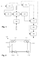
- the FIG. 1 is a schematic block diagram of an inventive plant for the production of solar panels.
- the solar panel 1 (see. FIG. 5 ) comprises as the base substrate a substantially rectangular glass plate 10 made of toughened safety glass.
- the solar cells are connected by longitudinal connector 31 and cross connector 33 in a conventional manner electrically connected.
- the solar panel 1 is arranged (eg, fixed on a building roof) in such a way that the glass plate 10 faces the sun.
- the solar radiation passes through the glass plate 10 and the first transparent plastic layer 20 and strikes the embedded between the plastic layers 20, 40 solar cells 30, where an electrical voltage is generated.
- the glass plate 10 is first provided with two markers in a marking and measuring stations 110 and measured.
- the measurement data is transmitted to a central database 120, which is part of an investment control, and stored therein.
- the glass plate 10 is cleaned and prepared for the further process steps.
- the solar cells 30 are first connected to the longitudinal connectors 31 to strings, then the strands are interconnected by means of the cross connector 33.
- the layer system is placed stepwise onto the glass plate 10, ie a first plastic film of EVA to form the first plastic layer 20, the interconnected solar cells 30 together with longitudinal and transverse connectors 31, 33, a second plastic film to form the second plastic layer 40 and the backsheet 50 are placed on the glass plate 10.
- laminating the module occurs in a laminator 160 Negative pressure and approx. 150 ° C.
- laminating form from the previously milky EVA plastic films clear, three-dimensionally crosslinked and no longer meltable plastic layers 20, 40, in which the solar cells 30 and the connectors are now embedded and firmly connected with each other and with the glass plate 10 and the backsheet 50 are.
- the EVA layers swell slightly over the outer edge of the glass plate 10 to the outside.
- the edges are lined in a cutting station 170, then in the next station 180, the contact areas of the cross connector 33 are exposed and finally in a further station 190, a junction box is set.
- the solar panel 1 can still be framed and measured and classified and packaged according to its electrical values.
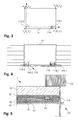
- the FIG. 2 is a schematic representation of the marking and measuring station 110.
- This comprises a support on which the glass plate 10 can be placed and holding devices 111 for holding the glass plate 10.
- Four cameras 112.1 ... 112.4 are arranged at the marking and measuring station 110, that their recording fields can capture the four corner regions of the glass plate 10.
- a marking head 113 along the longitudinal side of the glass plate 10 is arranged linearly movable.
- the method UniColor® from boraglas GmbH (see above) is used.
- the donor medium is first applied to the glass surface at the appropriate locations, for. B. glued as a film, after which by means of a laser housed in the marking head 113 laser to be marked areas are heated locally. Under the influence of the laser radiation, a glassy layer with silver nanoparticles is formed on the glass surface.
- FIG. 3 is a schematic representation of the generated marks. These include two placemarks 115.1, 115.2, each in the form of a cross, which have been produced in two corner regions of one of the longitudinal sides of the glass plate 10. Adjacent to the front placemark 115.1, a two-dimensional data matrix 116 has been applied to the glass surface in the same manner. It encodes a unique identification number for the glass plate 10. By the two placemarks 115.1, 115.2, a two-dimensional Cartesian coordinate system is defined, whose origin is given by the rear placemark 115.2. The x-axis extends from the origin through the front placemark 115.1, the y-axis is rotated counterclockwise by 90 ° to the x-axis. Each of the four corners P 1 ...
- P 4 detected by the cameras 112.1... 112.4 can be represented by an XY coordinate pair in this coordinate system. It should be noted that the x-axis does not necessarily have to run parallel to the longitudinal side of the glass plate 10, ie the placemarks 115.1, 115.2 need not be the same distance from the longitudinal side of the plate. It is for the functioning of the invention largely irrelevant where the two placemarks are mounted. In the sense of a good precision, it is advantageous if their distance is sufficiently large.
- the FIG. 4 is a schematic representation of the cutting station 170.
- This includes a turntable 171, on which the solar panel 1 can be placed.
- a turntable 171 On which the solar panel 1 can be placed, protrude portions of the backsheet (and optionally also the laminating layers) on the glass plate 10 out.
- Suction devices (not shown) hold the solar panel 1 on the support surface of the turntable 171 firmly.
- the turntable 171 allows in a conventional manner any rotational movements of the solar panel 1 and a transverse displacement of the same.
- a longitudinally displaceable cutting tool 172 is arranged on a longitudinal side of the turntable 171.
- the cutting station also has two cameras 175.1, 175.2, which are also arranged in the region of this longitudinal side and the distance is set so that they can detect the two placemarks 115.1, 115.2 and the data matrix 116.
- the front camera 175.1 simultaneously detects the front placemark 115.1 and the data matrix 116 arranged next to it in its recording field.
- FIG. 5 shows a schematic cross section through the cutting tool 172 and the processed edge region of the laminate 1.
- the cutting tool comprises a per se known, circular rotating cutting blade 173 and a support roller 174, which is supported on the axis of rotation of the cutting blade 173 opposite main side of the laminate 1.
- the cutting blade 173 is designed in such a way that sections of the backsheet 50 projecting beyond the glass plate 10 and of the laminating foils 20, 40 can be cut off.
- the Figures 6A-C serve to illustrate the method for cutting off the protruding edge region of the backsheet.
- the laminate 1 is first positioned on the turntable 171 so that the two placemarks 115.1, 115.2 and the data matrix 116 can be detected by the two cameras 175.1, 175.2 arranged at the cutting station 170.
- the one longitudinal side of the laminate 1 is thus approximately parallel to that edge of the support of the turntable 171, which is provided with the two cameras 175.1, 175.2 (see FIG. 6A ).
- the identification information read from the data matrix 116 is sent to the database, whereupon it returns the measurement data acquired to the plate 10 of the laminate 1 to the cutting station 170.
- the laminate 1 is then positioned on the basis of the obtained measurement data and the placemarks 115.1, 115.2 in such a way that the desired cutting line coincides with the travel path of the cutting tool 172.
- the cutting line has in the illustrated embodiment, a distance of 0.1 - 0.2 mm from the edge of the plate 10.
- the suction devices of the turntable 171 are activated, whereby the laminate 1 is securely held on the support of the turntable 171.
- the protruding portion of the backsheet and optionally the laminating films is separated, in the FIG. 6B is the result of this step.
- the laminate 1 is rotated by 90 ° and transversely displaced, so that a narrow side of the laminate 1 adjoins that edge of the support of the turntable 171 which is connected to the cameras 175.1 , 175.2 is provided.
- the positioning of the laminate 1 continues to take place on the basis of the acquired measurement data, however, a detection of the placemarks 115.1, 115.2 is no longer necessary in the further course, since the further positioning steps take place in each case relative to the previous position.
- the laminate 1 is again in a position such that the desired cutting line along the narrow side coincides with the travel of the cutting tool 172. Accordingly, by a linear movement of the cutting tool 172 again the protruding portion of the backsheet and optionally the laminating films are separated.
- a system according to the invention may comprise further stations, or individual stations may be missing.
- the geometry of the holding devices and transport devices for the glass plate or for the laminate as well as the number and arrangement of the cameras can be chosen differently.
- the position or the type of markings may be different, so different placemarks are conceivable, or the mark for identification is a barcode instead of a data matrix.
- the distance or angle values used and the corresponding coordinate system can also be chosen differently.
- combined distance and angle values may be used instead of the four data pairs in the Cartesian coordinate system, e.g. B. polar coordinates.
- the glass plate or the processing device can always be moved in each case.
- a processing device eg marking head, cutting device
- two opposing cutting devices may be provided which can simultaneously cut off protruding portions on two opposite sides of the laminate.
- the cutting device may also be structurally different.
- the invention provides a method and a plant which enable precise processing of laminates.
Priority Applications (3)
| Application Number | Priority Date | Filing Date | Title |
|---|---|---|---|
| EP08405137A EP2119679A1 (fr) | 2008-05-16 | 2008-05-16 | Procédé de traitement d'une strate |
| US12/992,659 US20110119898A1 (en) | 2008-05-16 | 2009-05-08 | Method for machining a laminate |
| PCT/CH2009/000150 WO2009137950A1 (fr) | 2008-05-16 | 2009-05-08 | Procédé de façonnage d'un stratifié |
Applications Claiming Priority (1)
| Application Number | Priority Date | Filing Date | Title |
|---|---|---|---|
| EP08405137A EP2119679A1 (fr) | 2008-05-16 | 2008-05-16 | Procédé de traitement d'une strate |
Publications (1)
| Publication Number | Publication Date |
|---|---|
| EP2119679A1 true EP2119679A1 (fr) | 2009-11-18 |
Family
ID=39760842
Family Applications (1)
| Application Number | Title | Priority Date | Filing Date |
|---|---|---|---|
| EP08405137A Withdrawn EP2119679A1 (fr) | 2008-05-16 | 2008-05-16 | Procédé de traitement d'une strate |
Country Status (3)
| Country | Link |
|---|---|
| US (1) | US20110119898A1 (fr) |
| EP (1) | EP2119679A1 (fr) |
| WO (1) | WO2009137950A1 (fr) |
Cited By (4)
| Publication number | Priority date | Publication date | Assignee | Title |
|---|---|---|---|---|
| CN102189338A (zh) * | 2010-03-05 | 2011-09-21 | 帆宣系统科技股份有限公司 | 太阳能板周边隔离线切割设备的切割方法 |
| WO2011139934A1 (fr) * | 2010-05-03 | 2011-11-10 | Corning Incorporated | Procédé de fabrication d'un article en verre en 3d |
| ITTO20120779A1 (it) * | 2012-09-10 | 2014-03-11 | Biesse Spa | Procedimento per l'asportazione della porzione di pellicola che sporge dai bordi di una lastra di vetro stratificata |
| DE102014204176B4 (de) | 2014-03-07 | 2021-11-11 | Biesse S.P.A. | Verfahren zum Abtragen des über die Kanten einer Verbundsicherheitsglastafel überstehenden Folienabschnitts |
Families Citing this family (7)
| Publication number | Priority date | Publication date | Assignee | Title |
|---|---|---|---|---|
| US20110220624A1 (en) * | 2010-03-10 | 2011-09-15 | Marketech International Corp. | Method for use of a device for cutting the peripheral isolation lines of solar panels |
| DE202012101120U1 (de) | 2012-03-29 | 2013-07-16 | Kuka Systems Gmbh | Bearbeitungseinrichtung |
| DE102016123865A1 (de) * | 2016-12-08 | 2018-06-14 | Schott Ag | Verfahren zum Weiterverarbeiten eines Glasrohr-Halbzeugs einschließlich einer thermischen Umformung |
| DE102016124833A1 (de) | 2016-12-19 | 2018-06-21 | Schott Ag | Verfahren zum Herstellen eines Hohlglasprodukts aus einem Glasrohr-Halbzeug mit Markierungen, sowie Verwendungen hiervon |
| IT201900023367A1 (it) * | 2019-12-09 | 2021-06-09 | Bottero Spa | Metodo e impianto di formatura per la realizzazione di una lastra di vetro stratificata |
| IT201900023394A1 (it) * | 2019-12-09 | 2021-06-09 | Bottero Spa | Metodo di formatura e macchina di rifilatura per la formatura di un prodotto semilavorato di vetro stratificato per la realizzazione di una lastra di vetro stratificata |
| CN112248606B (zh) * | 2020-09-27 | 2023-05-23 | 深圳双十科技有限公司 | Ocr贴合机内部测高组件及测高方法 |
Citations (11)
| Publication number | Priority date | Publication date | Assignee | Title |
|---|---|---|---|---|
| US4067764A (en) | 1977-03-15 | 1978-01-10 | Sierracin Corporation | Method of manufacture of solar cell panel |
| DE3428547C2 (fr) | 1983-08-02 | 1987-04-16 | Central Glass Co., Ltd., Ube, Yamaguchi, Jp | |
| DE19521022A1 (de) * | 1995-06-13 | 1996-12-19 | Heraeus Gmbh W C | Verfahren zur Herstellung eines Schichtverbundes |
| EP0845440B1 (fr) | 1996-11-29 | 2002-03-06 | Central Glass Company, Limited | Appareil pour couper la portion périférique d'un film sortant du côté périphérique d'une feuille de verre laminée |
| EP0861813B1 (fr) | 1997-02-28 | 2002-06-05 | BOTTERO S.p.A. | Appareil de coupe pour couper les rebords d'au moins une couche flexible utilisée pour recouvrir au moins une feuille |
| JP2004083321A (ja) * | 2002-08-26 | 2004-03-18 | Nippon Sheet Glass Co Ltd | 板状体の切断方法および切断装置 |
| DE10328617A1 (de) * | 2003-06-25 | 2005-01-13 | Hegla Fahrzeug- Und Maschinenbau Gmbh & Co Kg | Verfahren und Vorrichtung zur Kennzeichnung von Flachglasscheiben |
| EP1728770A2 (fr) | 2005-06-03 | 2006-12-06 | Boraglas GmbH | Procédé pour le marquage des surfaces d'objets |
| WO2007031151A1 (fr) | 2005-09-12 | 2007-03-22 | Boraglas Gmbh | Procede de production de structures en couleurs dans le verre et verre ainsi produit |
| WO2007062860A1 (fr) | 2005-12-02 | 2007-06-07 | Boraglas Gmbh | Procede pour marquer du verre de securite trempe |
| US20080011802A1 (en) * | 2006-07-14 | 2008-01-17 | Innolux Display Corp. | Cutting system for master liquid crystal panel having different alignment marks and method for cutting master liquid crystal panel |
Family Cites Families (44)
| Publication number | Priority date | Publication date | Assignee | Title |
|---|---|---|---|---|
| US2078386A (en) * | 1935-11-29 | 1937-04-27 | Michael B Kendis | Glass cutting mechanism |
| US2515445A (en) * | 1947-05-07 | 1950-07-18 | Dearborn Glass Company | Glass cutting machine |
| US2538901A (en) * | 1949-07-02 | 1951-01-23 | Red Devil Tools | Apparatus for cutting plate glass |
| US3424357A (en) * | 1966-07-28 | 1969-01-28 | Ppg Industries Inc | Automatically sizing and severing glass sheets |
| FR1572186A (fr) * | 1967-12-12 | 1969-06-27 | ||
| US3663333A (en) * | 1969-07-18 | 1972-05-16 | Fabreeka Products Co | Method of bonding material having a low coefficient of friction to a substrate |
| CH643478A5 (de) * | 1980-04-14 | 1984-06-15 | Erwin Jenkner | Besaeumeinrichtung fuer plattenfoermige werkstuecke mit ueberstehenden deckschichten. |
| DE3544251A1 (de) * | 1985-12-14 | 1987-06-19 | Duerkopp System Technik Gmbh | Verfahren und vorrichtung zum selbsttaetigen zuschneiden von teilen aus flaechigem naehgut nach mit unterschiedlichen konturen versehenen mustervorlagen auf einer koordinaten-schneidmaschine |
| FR2607444B1 (fr) * | 1986-12-02 | 1989-02-10 | Saint Gobain Vitrage | Dispositif de decoupe de feuilles de matiere plastique |
| US5244525A (en) * | 1987-11-02 | 1993-09-14 | Kimberly-Clark Corporation | Methods for bonding, cutting and printing polymeric materials using xerographic printing of IR absorbing material |
| IT1230916B (it) * | 1988-06-27 | 1991-11-08 | Central Glass Co Ltd | Dispositivo e metodo per tagliare parte di bordo superfluo di interstrato di vetro laminato |
| AT396085B (de) * | 1990-07-13 | 1993-05-25 | Gfm Fertigungstechnik | Vorrichtung zum beschneiden raeumlicher formteile aus kunststoff od. dgl. |
| JPH0783992B2 (ja) * | 1991-11-25 | 1995-09-13 | 池田物産株式会社 | 成形天井の端末処理方法 |
| JPH05345365A (ja) * | 1992-06-15 | 1993-12-27 | Sumitomo Bakelite Co Ltd | 積層板の製造方法 |
| DE59407644D1 (de) * | 1993-06-11 | 1999-02-25 | Isovolta | Verfahren zur herstellung fotovoltaischer module sowie eine vorrichtung zur durchführung dieses verfahrens |
| US5727913A (en) * | 1996-05-24 | 1998-03-17 | Naim; Moshe | Double edge trimming tool |
| US6119565A (en) * | 1997-06-13 | 2000-09-19 | Jere M. L'Heureux | Apparatus and method for electronically measuring and cutting floor coverings |
| JP4354029B2 (ja) * | 1998-09-04 | 2009-10-28 | 日清紡ホールディングス株式会社 | ラミネート装置における搬送装置 |
| JP3098003B2 (ja) * | 1998-09-24 | 2000-10-10 | 日清紡績株式会社 | 太陽電池におけるラミネート装置 |
| US6567116B1 (en) * | 1998-11-20 | 2003-05-20 | James A. Aman | Multiple object tracking system |
| JP3065309B1 (ja) * | 1999-03-11 | 2000-07-17 | 沖電気工業株式会社 | 半導体装置の製造方法 |
| EP1039551B2 (fr) * | 1999-03-23 | 2010-09-15 | Kaneka Corporation | Module photovoltaique |
| US6539830B1 (en) * | 1999-10-13 | 2003-04-01 | The Koskovich Company | Automated board processing apparatus |
| US7055418B2 (en) * | 2000-04-06 | 2006-06-06 | Fotoba International S.R.L. | Device for trimming and automatic cutting of images on paper and other graphic and photographic substrates, in particular of large size |
| JP2002036177A (ja) * | 2000-05-26 | 2002-02-05 | Gerber Technol Inc | シート部材の組合せを切り取る装置及び方法 |
| GB0114834D0 (en) * | 2001-06-18 | 2001-08-08 | Statefresh Ltd | A method of and apparatus for affixing backing to plates |
| US20030041959A1 (en) * | 2001-08-14 | 2003-03-06 | Moosey Cynthia M. | Pattern for glass cutting and method for using the pattern |
| JP2004139035A (ja) * | 2002-09-25 | 2004-05-13 | Seiko Epson Corp | 赤外カットフィルタ付レンズ及びその製造方法並びに小型カメラ |
| CN1846241A (zh) * | 2003-09-05 | 2006-10-11 | 东芝松下显示技术有限公司 | 制造显示设备的方法 |
| DE102004030411A1 (de) * | 2004-06-23 | 2006-01-19 | Kuraray Specialities Europe Gmbh | Solarmodul als Verbundsicherheitsglas |
| CA2504266C (fr) * | 2005-04-14 | 2013-08-13 | Relizon Canada Inc. | Methode et systeme de fabrication de trousses d'etiquettes composees de feuilles porteuses d'etiquettes de forme precise pouvant etre enlevees de ces feuilles |
| JP5058451B2 (ja) * | 2005-06-02 | 2012-10-24 | コーニングジャパン株式会社 | 板材の分断ユニット、この分断ユニットを有する分断装置、および、この分断装置を有する分断設備 |
| DE102005027964A1 (de) * | 2005-06-16 | 2006-12-28 | Peter Lisec | Verfahren und Vorrichtung zum Entfernen des Kunststofffolienüberstandes bei Verbundglasplatten |
| TWI393682B (zh) * | 2005-07-06 | 2013-04-21 | Mitsuboshi Diamond Ind Co Ltd | A scribing method for brittle materials and a method of manufacturing the same, using the scribing method of the scribing wheel and the scribing device, and the scribing tool |
| ES2560660T3 (es) * | 2005-12-29 | 2016-02-22 | Airbus Operations S.L. | Procedimiento y útiles para la fabricación de cuadernas de material compuesto |
| JP5178536B2 (ja) * | 2006-03-01 | 2013-04-10 | ライオン ブラザーズ カンパニー,インコーポレイテッド | デジタル印刷したアップリケ表像体 |
| JP2007277032A (ja) * | 2006-04-05 | 2007-10-25 | Alps Engineering Co Ltd | ガラスパネル切断装置 |
| US20080017304A1 (en) * | 2006-07-21 | 2008-01-24 | Dow Global Technologies Inc. | Parts with edges of plastic and fabric and processes for their production |
| JP2008069063A (ja) * | 2006-09-15 | 2008-03-27 | Alps Engineering Co Ltd | ガラスパネル切断装置 |
| JP5492375B2 (ja) * | 2007-09-25 | 2014-05-14 | 株式会社シライテック | ガラス基板の切断装置 |
| DE102008031061A1 (de) * | 2008-07-01 | 2011-01-05 | Grenzebach Maschinenbau Gmbh | Verfahren und Vorrichtung zum Besäumen photovoltaischer Module |
| EP2174784A1 (fr) * | 2008-10-13 | 2010-04-14 | 3S Swiss Solar Systems AG | Procédé destiné à séparer une section saillante d'une couche de strate |
| JP5868122B2 (ja) * | 2011-10-31 | 2016-02-24 | Jukiオートメーションシステムズ株式会社 | 基板処理装置、テーブル機構、位置決め方法及びプログラム |
| US20140028162A1 (en) * | 2012-07-26 | 2014-01-30 | Michelle Lynn Carlson | Case for portable electronic device |
-
2008
- 2008-05-16 EP EP08405137A patent/EP2119679A1/fr not_active Withdrawn
-
2009
- 2009-05-08 WO PCT/CH2009/000150 patent/WO2009137950A1/fr active Application Filing
- 2009-05-08 US US12/992,659 patent/US20110119898A1/en not_active Abandoned
Patent Citations (11)
| Publication number | Priority date | Publication date | Assignee | Title |
|---|---|---|---|---|
| US4067764A (en) | 1977-03-15 | 1978-01-10 | Sierracin Corporation | Method of manufacture of solar cell panel |
| DE3428547C2 (fr) | 1983-08-02 | 1987-04-16 | Central Glass Co., Ltd., Ube, Yamaguchi, Jp | |
| DE19521022A1 (de) * | 1995-06-13 | 1996-12-19 | Heraeus Gmbh W C | Verfahren zur Herstellung eines Schichtverbundes |
| EP0845440B1 (fr) | 1996-11-29 | 2002-03-06 | Central Glass Company, Limited | Appareil pour couper la portion périférique d'un film sortant du côté périphérique d'une feuille de verre laminée |
| EP0861813B1 (fr) | 1997-02-28 | 2002-06-05 | BOTTERO S.p.A. | Appareil de coupe pour couper les rebords d'au moins une couche flexible utilisée pour recouvrir au moins une feuille |
| JP2004083321A (ja) * | 2002-08-26 | 2004-03-18 | Nippon Sheet Glass Co Ltd | 板状体の切断方法および切断装置 |
| DE10328617A1 (de) * | 2003-06-25 | 2005-01-13 | Hegla Fahrzeug- Und Maschinenbau Gmbh & Co Kg | Verfahren und Vorrichtung zur Kennzeichnung von Flachglasscheiben |
| EP1728770A2 (fr) | 2005-06-03 | 2006-12-06 | Boraglas GmbH | Procédé pour le marquage des surfaces d'objets |
| WO2007031151A1 (fr) | 2005-09-12 | 2007-03-22 | Boraglas Gmbh | Procede de production de structures en couleurs dans le verre et verre ainsi produit |
| WO2007062860A1 (fr) | 2005-12-02 | 2007-06-07 | Boraglas Gmbh | Procede pour marquer du verre de securite trempe |
| US20080011802A1 (en) * | 2006-07-14 | 2008-01-17 | Innolux Display Corp. | Cutting system for master liquid crystal panel having different alignment marks and method for cutting master liquid crystal panel |
Non-Patent Citations (1)
| Title |
|---|
| LENK, A.; MORGENTHAL, L., DAMAGE-FREE MICROMARKING OF GLASS. GLASTECHN. BER. GLASS SCI. TECHNOL., vol. 73, no. 9, 2000, pages 285 - 289 |
Cited By (7)
| Publication number | Priority date | Publication date | Assignee | Title |
|---|---|---|---|---|
| CN102189338A (zh) * | 2010-03-05 | 2011-09-21 | 帆宣系统科技股份有限公司 | 太阳能板周边隔离线切割设备的切割方法 |
| WO2011139934A1 (fr) * | 2010-05-03 | 2011-11-10 | Corning Incorporated | Procédé de fabrication d'un article en verre en 3d |
| CN102883856A (zh) * | 2010-05-03 | 2013-01-16 | 康宁股份有限公司 | 制造3d玻璃制品的方法 |
| US8713968B2 (en) | 2010-05-03 | 2014-05-06 | Corning Incorporated | Method and apparatus for making a 3D glass article |
| CN102883856B (zh) * | 2010-05-03 | 2016-05-25 | 康宁股份有限公司 | 制造3d玻璃制品的方法 |
| ITTO20120779A1 (it) * | 2012-09-10 | 2014-03-11 | Biesse Spa | Procedimento per l'asportazione della porzione di pellicola che sporge dai bordi di una lastra di vetro stratificata |
| DE102014204176B4 (de) | 2014-03-07 | 2021-11-11 | Biesse S.P.A. | Verfahren zum Abtragen des über die Kanten einer Verbundsicherheitsglastafel überstehenden Folienabschnitts |
Also Published As
| Publication number | Publication date |
|---|---|
| US20110119898A1 (en) | 2011-05-26 |
| WO2009137950A1 (fr) | 2009-11-19 |
Similar Documents
| Publication | Publication Date | Title |
|---|---|---|
| EP2119679A1 (fr) | Procédé de traitement d'une strate | |
| EP3095075B1 (fr) | Procédé et dispositif de traitement d'un substrat | |
| EP2180981B1 (fr) | Outil robot, système robot et procédé de traitement de pièces | |
| EP1880790B1 (fr) | Installation destinée à la structuration de modules solaires | |
| EP2174784A1 (fr) | Procédé destiné à séparer une section saillante d'une couche de strate | |
| DE102006035031B4 (de) | Verfahren zum Bearbeiten eines Halbleiterwafers | |
| EP2485867B1 (fr) | Dispositif et procede pour le deblocage des pieces optiques, en particulier lentilles ophthalmiques | |
| EP2291263A2 (fr) | Procédé et dispositif destiné à rogner les bords de modules photovoltaïques | |
| DE102013104745B4 (de) | Verfahren und Vorrichtung zur Herstellung eines Sicherheitsdokuments | |
| DE102009048442A1 (de) | Vorrichtung und Verfahren zum Ausrichten von Werkstücken | |
| DE102008021997B4 (de) | Plattenaufteilanlage | |
| EP1982808A1 (fr) | Dispositif d'amélioration de défauts dans une pièce en bois | |
| EP3372331B1 (fr) | Procédé de répartition d'une pièce à usiner en forme de plaque | |
| EP1570927A1 (fr) | Dispositif d'alimentation pour machine à cinter les tôles avec un dispositif d'éclairage | |
| DE202008008794U1 (de) | Vorrichtung zum Besäumen photovoltaischer Module | |
| DE202019102050U1 (de) | Markiersystem und Laserschneidmaschine | |
| WO2004113242A1 (fr) | Procede et dispositif de marquage de plaques de verre plates | |
| DE102017002270B4 (de) | Verfahren zum Messen des Formats eines plattenförmigen Werkstücks | |
| DE102017118761A1 (de) | Fertigungszelle und Verfahren zum Rüsten einer Fertigungszelle | |
| DE102015119424A1 (de) | Verfahren zum Bearbeiten zumindest eines Werkstücks | |
| EP1741517B1 (fr) | Dispositif de fixation à dépression pour une pièce plate et méthode de fabrication de la pièce plate | |
| DE102016112268A1 (de) | Einrichtung und Verfahren zur Positionierung einer Flachglaseinheit | |
| AT500076B1 (de) | Vorrichtung und verfahren zum aufbringen eines flächigen verbindungsmittels auf eine kontaktfläche eines wafers | |
| EP3636437A1 (fr) | Procédé de montage d'une plaque d'impression à un cylindre d'impression, dispositif d'application d'une plaque d'impression à un cylindre d'impression, procédé de fabrication d'une plaque d'impression, plaque d'impression destinée à l'utilisation dans un procédé de flexographie et dispositif de coupage des bords d'une plaque d'impression | |
| DE102016122355B4 (de) | Bearbeitungsanlage und Verfahren zum Bearbeiten eines plattenförmigen Objekts |
Legal Events
| Date | Code | Title | Description |
|---|---|---|---|
| PUAI | Public reference made under article 153(3) epc to a published international application that has entered the european phase |
Free format text: ORIGINAL CODE: 0009012 |
|
| AK | Designated contracting states |
Kind code of ref document: A1 Designated state(s): AT BE BG CH CY CZ DE DK EE ES FI FR GB GR HR HU IE IS IT LI LT LU LV MC MT NL NO PL PT RO SE SI SK TR |
|
| AX | Request for extension of the european patent |
Extension state: AL BA MK RS |
|
| AKX | Designation fees paid | ||
| REG | Reference to a national code |
Ref country code: DE Ref legal event code: 8566 |
|
| STAA | Information on the status of an ep patent application or granted ep patent |
Free format text: STATUS: THE APPLICATION IS DEEMED TO BE WITHDRAWN |
|
| 18D | Application deemed to be withdrawn |
Effective date: 20100519 |