EP2119679A1 - Method for processing a laminate - Google Patents
Method for processing a laminate Download PDFInfo
- Publication number
- EP2119679A1 EP2119679A1 EP08405137A EP08405137A EP2119679A1 EP 2119679 A1 EP2119679 A1 EP 2119679A1 EP 08405137 A EP08405137 A EP 08405137A EP 08405137 A EP08405137 A EP 08405137A EP 2119679 A1 EP2119679 A1 EP 2119679A1
- Authority
- EP
- European Patent Office
- Prior art keywords
- laminate
- station
- processing
- distance
- fixed plate
- Prior art date
- Legal status (The legal status is an assumption and is not a legal conclusion. Google has not performed a legal analysis and makes no representation as to the accuracy of the status listed.)
- Withdrawn
Links
- 238000012545 processing Methods 0.000 title claims abstract description 42
- 238000000034 method Methods 0.000 title claims abstract description 35
- 239000011521 glass Substances 0.000 claims abstract description 49
- 238000003475 lamination Methods 0.000 claims abstract description 15
- 238000005259 measurement Methods 0.000 claims abstract description 7
- 238000005520 cutting process Methods 0.000 claims description 63
- 238000010030 laminating Methods 0.000 claims description 13
- 239000007787 solid Substances 0.000 claims description 12
- 238000009434 installation Methods 0.000 claims description 6
- 238000012937 correction Methods 0.000 claims description 4
- 239000003550 marker Substances 0.000 claims description 4
- 238000003754 machining Methods 0.000 claims 1
- 230000008569 process Effects 0.000 abstract description 8
- 239000011159 matrix material Substances 0.000 description 8
- 239000005038 ethylene vinyl acetate Substances 0.000 description 7
- 229920003023 plastic Polymers 0.000 description 7
- 238000004519 manufacturing process Methods 0.000 description 6
- 230000005855 radiation Effects 0.000 description 6
- DQXBYHZEEUGOBF-UHFFFAOYSA-N but-3-enoic acid;ethene Chemical compound C=C.OC(=O)CC=C DQXBYHZEEUGOBF-UHFFFAOYSA-N 0.000 description 5
- 239000004033 plastic Substances 0.000 description 5
- 229920001200 poly(ethylene-vinyl acetate) Polymers 0.000 description 5
- 238000000926 separation method Methods 0.000 description 5
- 238000001514 detection method Methods 0.000 description 4
- 230000002093 peripheral effect Effects 0.000 description 4
- FOIXSVOLVBLSDH-UHFFFAOYSA-N Silver ion Chemical compound [Ag+] FOIXSVOLVBLSDH-UHFFFAOYSA-N 0.000 description 3
- 230000006378 damage Effects 0.000 description 3
- 238000005516 engineering process Methods 0.000 description 3
- 239000005340 laminated glass Substances 0.000 description 3
- 239000002985 plastic film Substances 0.000 description 3
- 229920006255 plastic film Polymers 0.000 description 3
- 239000000758 substrate Substances 0.000 description 3
- 238000010586 diagram Methods 0.000 description 2
- 238000006073 displacement reaction Methods 0.000 description 2
- 239000005357 flat glass Substances 0.000 description 2
- 230000001939 inductive effect Effects 0.000 description 2
- 229920000728 polyester Polymers 0.000 description 2
- XUIMIQQOPSSXEZ-UHFFFAOYSA-N Silicon Chemical compound [Si] XUIMIQQOPSSXEZ-UHFFFAOYSA-N 0.000 description 1
- 208000027418 Wounds and injury Diseases 0.000 description 1
- 238000013459 approach Methods 0.000 description 1
- 230000008901 benefit Effects 0.000 description 1
- 238000004140 cleaning Methods 0.000 description 1
- 230000009849 deactivation Effects 0.000 description 1
- 230000000694 effects Effects 0.000 description 1
- 239000011888 foil Substances 0.000 description 1
- 239000012535 impurity Substances 0.000 description 1
- 208000014674 injury Diseases 0.000 description 1
- 238000007641 inkjet printing Methods 0.000 description 1
- 238000005342 ion exchange Methods 0.000 description 1
- 230000001788 irregular Effects 0.000 description 1
- 239000000463 material Substances 0.000 description 1
- 229910052751 metal Inorganic materials 0.000 description 1
- 239000002184 metal Substances 0.000 description 1
- 238000012986 modification Methods 0.000 description 1
- 230000004048 modification Effects 0.000 description 1
- 229920002620 polyvinyl fluoride Polymers 0.000 description 1
- 239000005336 safety glass Substances 0.000 description 1
- 238000007790 scraping Methods 0.000 description 1
- 229910052710 silicon Inorganic materials 0.000 description 1
- 239000010703 silicon Substances 0.000 description 1
- 229910052709 silver Inorganic materials 0.000 description 1
- 239000004332 silver Substances 0.000 description 1
- -1 silver ions Chemical class 0.000 description 1
- 239000000779 smoke Substances 0.000 description 1
- 239000000126 substance Substances 0.000 description 1
- 230000008961 swelling Effects 0.000 description 1
- 239000005341 toughened glass Substances 0.000 description 1
- 230000007704 transition Effects 0.000 description 1
- 238000009966 trimming Methods 0.000 description 1
Images

Classifications
-
- C—CHEMISTRY; METALLURGY
- C03—GLASS; MINERAL OR SLAG WOOL
- C03B—MANUFACTURE, SHAPING, OR SUPPLEMENTARY PROCESSES
- C03B33/00—Severing cooled glass
- C03B33/07—Cutting armoured, multi-layered, coated or laminated, glass products
- C03B33/074—Glass products comprising an outer layer or surface coating of non-glass material
-
- B—PERFORMING OPERATIONS; TRANSPORTING
- B26—HAND CUTTING TOOLS; CUTTING; SEVERING
- B26D—CUTTING; DETAILS COMMON TO MACHINES FOR PERFORATING, PUNCHING, CUTTING-OUT, STAMPING-OUT OR SEVERING
- B26D1/00—Cutting through work characterised by the nature or movement of the cutting member or particular materials not otherwise provided for; Apparatus or machines therefor; Cutting members therefor
- B26D1/01—Cutting through work characterised by the nature or movement of the cutting member or particular materials not otherwise provided for; Apparatus or machines therefor; Cutting members therefor involving a cutting member which does not travel with the work
- B26D1/04—Cutting through work characterised by the nature or movement of the cutting member or particular materials not otherwise provided for; Apparatus or machines therefor; Cutting members therefor involving a cutting member which does not travel with the work having a linearly-movable cutting member
- B26D1/045—Cutting through work characterised by the nature or movement of the cutting member or particular materials not otherwise provided for; Apparatus or machines therefor; Cutting members therefor involving a cutting member which does not travel with the work having a linearly-movable cutting member for thin material, e.g. for sheets, strips or the like
-
- B—PERFORMING OPERATIONS; TRANSPORTING
- B26—HAND CUTTING TOOLS; CUTTING; SEVERING
- B26D—CUTTING; DETAILS COMMON TO MACHINES FOR PERFORATING, PUNCHING, CUTTING-OUT, STAMPING-OUT OR SEVERING
- B26D7/00—Details of apparatus for cutting, cutting-out, stamping-out, punching, perforating, or severing by means other than cutting
- B26D7/01—Means for holding or positioning work
-
- B—PERFORMING OPERATIONS; TRANSPORTING
- B32—LAYERED PRODUCTS
- B32B—LAYERED PRODUCTS, i.e. PRODUCTS BUILT-UP OF STRATA OF FLAT OR NON-FLAT, e.g. CELLULAR OR HONEYCOMB, FORM
- B32B17/00—Layered products essentially comprising sheet glass, or glass, slag, or like fibres
- B32B17/06—Layered products essentially comprising sheet glass, or glass, slag, or like fibres comprising glass as the main or only constituent of a layer, next to another layer of a specific material
- B32B17/10—Layered products essentially comprising sheet glass, or glass, slag, or like fibres comprising glass as the main or only constituent of a layer, next to another layer of a specific material of synthetic resin
- B32B17/10005—Layered products essentially comprising sheet glass, or glass, slag, or like fibres comprising glass as the main or only constituent of a layer, next to another layer of a specific material of synthetic resin laminated safety glass or glazing
- B32B17/10009—Layered products essentially comprising sheet glass, or glass, slag, or like fibres comprising glass as the main or only constituent of a layer, next to another layer of a specific material of synthetic resin laminated safety glass or glazing characterized by the number, the constitution or treatment of glass sheets
- B32B17/10018—Layered products essentially comprising sheet glass, or glass, slag, or like fibres comprising glass as the main or only constituent of a layer, next to another layer of a specific material of synthetic resin laminated safety glass or glazing characterized by the number, the constitution or treatment of glass sheets comprising only one glass sheet
-
- B—PERFORMING OPERATIONS; TRANSPORTING
- B32—LAYERED PRODUCTS
- B32B—LAYERED PRODUCTS, i.e. PRODUCTS BUILT-UP OF STRATA OF FLAT OR NON-FLAT, e.g. CELLULAR OR HONEYCOMB, FORM
- B32B17/00—Layered products essentially comprising sheet glass, or glass, slag, or like fibres
- B32B17/06—Layered products essentially comprising sheet glass, or glass, slag, or like fibres comprising glass as the main or only constituent of a layer, next to another layer of a specific material
- B32B17/10—Layered products essentially comprising sheet glass, or glass, slag, or like fibres comprising glass as the main or only constituent of a layer, next to another layer of a specific material of synthetic resin
- B32B17/10005—Layered products essentially comprising sheet glass, or glass, slag, or like fibres comprising glass as the main or only constituent of a layer, next to another layer of a specific material of synthetic resin laminated safety glass or glazing
- B32B17/1055—Layered products essentially comprising sheet glass, or glass, slag, or like fibres comprising glass as the main or only constituent of a layer, next to another layer of a specific material of synthetic resin laminated safety glass or glazing characterized by the resin layer, i.e. interlayer
- B32B17/10788—Layered products essentially comprising sheet glass, or glass, slag, or like fibres comprising glass as the main or only constituent of a layer, next to another layer of a specific material of synthetic resin laminated safety glass or glazing characterized by the resin layer, i.e. interlayer containing ethylene vinylacetate
-
- B—PERFORMING OPERATIONS; TRANSPORTING
- B32—LAYERED PRODUCTS
- B32B—LAYERED PRODUCTS, i.e. PRODUCTS BUILT-UP OF STRATA OF FLAT OR NON-FLAT, e.g. CELLULAR OR HONEYCOMB, FORM
- B32B17/00—Layered products essentially comprising sheet glass, or glass, slag, or like fibres
- B32B17/06—Layered products essentially comprising sheet glass, or glass, slag, or like fibres comprising glass as the main or only constituent of a layer, next to another layer of a specific material
- B32B17/10—Layered products essentially comprising sheet glass, or glass, slag, or like fibres comprising glass as the main or only constituent of a layer, next to another layer of a specific material of synthetic resin
- B32B17/10005—Layered products essentially comprising sheet glass, or glass, slag, or like fibres comprising glass as the main or only constituent of a layer, next to another layer of a specific material of synthetic resin laminated safety glass or glazing
- B32B17/10807—Making laminated safety glass or glazing; Apparatus therefor
- B32B17/10899—Making laminated safety glass or glazing; Apparatus therefor by introducing interlayers of synthetic resin
- B32B17/10954—Making laminated safety glass or glazing; Apparatus therefor by introducing interlayers of synthetic resin by using an aligning laminating device
-
- B—PERFORMING OPERATIONS; TRANSPORTING
- B32—LAYERED PRODUCTS
- B32B—LAYERED PRODUCTS, i.e. PRODUCTS BUILT-UP OF STRATA OF FLAT OR NON-FLAT, e.g. CELLULAR OR HONEYCOMB, FORM
- B32B17/00—Layered products essentially comprising sheet glass, or glass, slag, or like fibres
- B32B17/06—Layered products essentially comprising sheet glass, or glass, slag, or like fibres comprising glass as the main or only constituent of a layer, next to another layer of a specific material
- B32B17/10—Layered products essentially comprising sheet glass, or glass, slag, or like fibres comprising glass as the main or only constituent of a layer, next to another layer of a specific material of synthetic resin
- B32B17/10005—Layered products essentially comprising sheet glass, or glass, slag, or like fibres comprising glass as the main or only constituent of a layer, next to another layer of a specific material of synthetic resin laminated safety glass or glazing
- B32B17/10807—Making laminated safety glass or glazing; Apparatus therefor
- B32B17/1099—After-treatment of the layered product, e.g. cooling
-
- B—PERFORMING OPERATIONS; TRANSPORTING
- B32—LAYERED PRODUCTS
- B32B—LAYERED PRODUCTS, i.e. PRODUCTS BUILT-UP OF STRATA OF FLAT OR NON-FLAT, e.g. CELLULAR OR HONEYCOMB, FORM
- B32B38/00—Ancillary operations in connection with laminating processes
- B32B38/0004—Cutting, tearing or severing, e.g. bursting; Cutter details
-
- B—PERFORMING OPERATIONS; TRANSPORTING
- B32—LAYERED PRODUCTS
- B32B—LAYERED PRODUCTS, i.e. PRODUCTS BUILT-UP OF STRATA OF FLAT OR NON-FLAT, e.g. CELLULAR OR HONEYCOMB, FORM
- B32B38/00—Ancillary operations in connection with laminating processes
- B32B38/10—Removing layers, or parts of layers, mechanically or chemically
- B32B38/105—Removing layers, or parts of layers, mechanically or chemically on edges
-
- C—CHEMISTRY; METALLURGY
- C03—GLASS; MINERAL OR SLAG WOOL
- C03B—MANUFACTURE, SHAPING, OR SUPPLEMENTARY PROCESSES
- C03B33/00—Severing cooled glass
- C03B33/02—Cutting or splitting sheet glass or ribbons; Apparatus or machines therefor
-
- C—CHEMISTRY; METALLURGY
- C03—GLASS; MINERAL OR SLAG WOOL
- C03B—MANUFACTURE, SHAPING, OR SUPPLEMENTARY PROCESSES
- C03B33/00—Severing cooled glass
- C03B33/02—Cutting or splitting sheet glass or ribbons; Apparatus or machines therefor
- C03B33/023—Cutting or splitting sheet glass or ribbons; Apparatus or machines therefor the sheet or ribbon being in a horizontal position
- C03B33/037—Controlling or regulating
-
- H—ELECTRICITY
- H01—ELECTRIC ELEMENTS
- H01L—SEMICONDUCTOR DEVICES NOT COVERED BY CLASS H10
- H01L31/00—Semiconductor devices sensitive to infrared radiation, light, electromagnetic radiation of shorter wavelength or corpuscular radiation and specially adapted either for the conversion of the energy of such radiation into electrical energy or for the control of electrical energy by such radiation; Processes or apparatus specially adapted for the manufacture or treatment thereof or of parts thereof; Details thereof
- H01L31/04—Semiconductor devices sensitive to infrared radiation, light, electromagnetic radiation of shorter wavelength or corpuscular radiation and specially adapted either for the conversion of the energy of such radiation into electrical energy or for the control of electrical energy by such radiation; Processes or apparatus specially adapted for the manufacture or treatment thereof or of parts thereof; Details thereof adapted as photovoltaic [PV] conversion devices
- H01L31/042—PV modules or arrays of single PV cells
- H01L31/048—Encapsulation of modules
-
- B—PERFORMING OPERATIONS; TRANSPORTING
- B26—HAND CUTTING TOOLS; CUTTING; SEVERING
- B26D—CUTTING; DETAILS COMMON TO MACHINES FOR PERFORATING, PUNCHING, CUTTING-OUT, STAMPING-OUT OR SEVERING
- B26D7/00—Details of apparatus for cutting, cutting-out, stamping-out, punching, perforating, or severing by means other than cutting
- B26D2007/0012—Details, accessories or auxiliary or special operations not otherwise provided for
- B26D2007/0068—Trimming and removing web edges
-
- B—PERFORMING OPERATIONS; TRANSPORTING
- B26—HAND CUTTING TOOLS; CUTTING; SEVERING
- B26D—CUTTING; DETAILS COMMON TO MACHINES FOR PERFORATING, PUNCHING, CUTTING-OUT, STAMPING-OUT OR SEVERING
- B26D5/00—Arrangements for operating and controlling machines or devices for cutting, cutting-out, stamping-out, punching, perforating, or severing by means other than cutting
-
- B—PERFORMING OPERATIONS; TRANSPORTING
- B32—LAYERED PRODUCTS
- B32B—LAYERED PRODUCTS, i.e. PRODUCTS BUILT-UP OF STRATA OF FLAT OR NON-FLAT, e.g. CELLULAR OR HONEYCOMB, FORM
- B32B2367/00—Polyesters, e.g. PET, i.e. polyethylene terephthalate
-
- B—PERFORMING OPERATIONS; TRANSPORTING
- B32—LAYERED PRODUCTS
- B32B—LAYERED PRODUCTS, i.e. PRODUCTS BUILT-UP OF STRATA OF FLAT OR NON-FLAT, e.g. CELLULAR OR HONEYCOMB, FORM
- B32B2457/00—Electrical equipment
- B32B2457/12—Photovoltaic modules
-
- Y—GENERAL TAGGING OF NEW TECHNOLOGICAL DEVELOPMENTS; GENERAL TAGGING OF CROSS-SECTIONAL TECHNOLOGIES SPANNING OVER SEVERAL SECTIONS OF THE IPC; TECHNICAL SUBJECTS COVERED BY FORMER USPC CROSS-REFERENCE ART COLLECTIONS [XRACs] AND DIGESTS
- Y02—TECHNOLOGIES OR APPLICATIONS FOR MITIGATION OR ADAPTATION AGAINST CLIMATE CHANGE
- Y02E—REDUCTION OF GREENHOUSE GAS [GHG] EMISSIONS, RELATED TO ENERGY GENERATION, TRANSMISSION OR DISTRIBUTION
- Y02E10/00—Energy generation through renewable energy sources
- Y02E10/50—Photovoltaic [PV] energy
-
- Y—GENERAL TAGGING OF NEW TECHNOLOGICAL DEVELOPMENTS; GENERAL TAGGING OF CROSS-SECTIONAL TECHNOLOGIES SPANNING OVER SEVERAL SECTIONS OF THE IPC; TECHNICAL SUBJECTS COVERED BY FORMER USPC CROSS-REFERENCE ART COLLECTIONS [XRACs] AND DIGESTS
- Y10—TECHNICAL SUBJECTS COVERED BY FORMER USPC
- Y10T—TECHNICAL SUBJECTS COVERED BY FORMER US CLASSIFICATION
- Y10T29/00—Metal working
- Y10T29/49—Method of mechanical manufacture
- Y10T29/4998—Combined manufacture including applying or shaping of fluent material
-
- Y—GENERAL TAGGING OF NEW TECHNOLOGICAL DEVELOPMENTS; GENERAL TAGGING OF CROSS-SECTIONAL TECHNOLOGIES SPANNING OVER SEVERAL SECTIONS OF THE IPC; TECHNICAL SUBJECTS COVERED BY FORMER USPC CROSS-REFERENCE ART COLLECTIONS [XRACs] AND DIGESTS
- Y10—TECHNICAL SUBJECTS COVERED BY FORMER USPC
- Y10T—TECHNICAL SUBJECTS COVERED BY FORMER US CLASSIFICATION
- Y10T29/00—Metal working
- Y10T29/51—Plural diverse manufacturing apparatus including means for metal shaping or assembling
Definitions
- the invention relates to a method for processing a laminate, which has at least one fixed plate, in particular a glass plate.
- the invention further relates to a system for processing such a laminate.
- Laminates have a wide range of applications and can have very different layer systems.
- One group of laminates has one or more solid plates which impart dimensional stability to the laminate. Glass plates are often used as solid plates, especially if the laminate is to be completely or partially transparent. Examples of such laminates are laminated glasses, which are used in automotive or building glazing.
- solar panels also called solar modules. It is known to construct such solar panels by electrically connecting a plurality of mechanically sensitive solar cells (photovoltaic cells, eg silicon-based thick-film solar cells) and enclosing them in a layer system.
- the layer system provides mechanical stability and protects the enclosed cells from the effects of the weather or mechanical damage.
- the layer system may, for example, be based on a glass substrate transparent to the relevant portions of the solar radiation and a backsheet between which the solar cells and the electrical connectors connecting them are enclosed. Films of EVA (ethylene vinyl acetate) or other suitable material are incorporated between said layers so that the layer system can be laminated together under the influence of heat and pressure.
- the solar cells can be enclosed by a frame.
- the EP 0 861 813 B1 (Bottero ) relates to a cutting device for cutting off a peripheral portion of a flexible layer which projects beyond a plate which is coated with the layer, e.g. For trimming intermediate layers in laminated glass production.
- the device comprises a motor-driven rotating cutting disc and stop means for the peripheral portion, which are arranged tangentially on a peripheral surface of the cutting disc and exert a counterforce to the force of the cutting disc at the cutting point.
- the stop means may comprise a rotatable stop disc whose axis is preferably oriented obliquely to the axis of the cutting disc 34.
- the DE 34 28 547 C2 (Central Glass / Toray Engineering) relates to a cutting device for cutting an outer seam of an intermediate layer of PVB arranged between the sheet glass layers and extending beyond the area of plate glass layers.
- a band blade unit movable along the circumference of the glass layers is used.
- the cutting device comprises a slider with a scraping edge and means for rejecting the cut-off outer seam. The cutter is guided along the outer edge of the glass sheet layers of the laminate during cutting.
- the EP 0 845 440 B1 (Central Glass) relates to another device for cutting off the edge region of an intermediate layer of a laminated glass plate.
- the device comprises a robot arm with a robot hand holding a detachable cutting blade; The cutting blade is moved away from the edge region of the glass plate when a certain resistance force is exceeded.
- the object of the invention is to provide a method of the technical field mentioned above and a corresponding system, which allow precise processing of laminates.
- At least one location mark is applied to the fixed plate prior to the lamination step and at least one distance and / or angle value of the fixed plate relative to the location mark is determined.
- the laminate is processed, wherein the laminate and a processing tool are automatically positioned relative to each other depending on the location mark and the at least one distance and / or angle value.
- a distance value may be a distance of an edge or a corner from the placemark.
- the values can also be measured in a coordination system defined by the placemark or multiple placemarks.
- An angle value results from an angle between two straight lines which are defined by the fixed plate and / or the location marks or which result from the coordinate system.
- the solid plate Before the lamination, the solid plate can be easily measured, its edge can be detected both mechanically (eg by a sensor) and non-contact (eg visually by means of a camera), and conventional, in particular automated, methods can be used to measure. After lamination, the detection of the edges of the solid plate is made difficult or virtually impossible. However, within the scope of the invention, the processing can be carried out based on the attached location marks and the detected distance and / or angle value (or a plurality of such values). It is thus no longer necessary to detect the edge of the solid plate after lamination.
- the marking station and the measuring station can be structurally integrated in a single station (marking and measuring station), but there may also be two stations arranged one behind the other.
- the placemark can be applied by various methods (known per se). It is thus known to produce inscriptions and markings in the interior of glass substrates by means of focused laser radiation (cf. Lenk, A .; Morgenthal, L .: Damage-free micromarking of glass. Glastechn. Ber. Glass Sci. Technol. 73 (2000) No. 9, 285-289 ). These methods offer the advantage that no additional substances must be used, the markings produced are also extremely wear-resistant.
- inkjet printing an established technology for creating markings on glass and other solid surfaces.
- the technologies offered under the brand names MarcColor® or UniColor® by boraglas GmbH, Halle (Germany) are particularly preferred, see also WO 07/031151 A1 .
- WO 07/062860 A1 and EP 1 728 770 A2 all boraglas GmbH.
- a donor medium is applied to the glass surface.
- an ion exchange is induced by means of focused laser radiation, silver ions diffuse into the glass and combine to form silver nanoparticles in the interior of the glass.
- a glassy layer with silver nanoparticles is formed with the aid of laser radiation at the transition from the donor medium to the glass surface.
- marking technologies such as: As the exact location applying a sticker, are also used in the invention.
- optically readable markings which allow a particularly high position accuracy, for example, inductive or capacitive detectable markings are conceivable.
- two mutually distanced placemarks are attached to the fixed plate, so that on the basis of both the positioning and the orientation of the fixed plate is always clearly determined.
- the marking station may include a movably arranged marking head that can be moved to the appropriate positions.
- the plate to be marked is moved relative to a marking device.
- the inventive method is particularly suitable for separating a projecting portion of a layer of the laminate, in particular a backsheet, wherein in the processing step, the laminate and a cutting tool for separating the protruding portion depending on the placemark and the at least one distance and / or angle automatically be positioned relative to each other.
- the separation of the backsheet (which is made of polyester or polyvinyl fluoride, for example) has different requirements than the separation of intermediate laminate layers enclosed between two glass plates (and possibly further layers).
- the processing station is designed as a cutting station and comprises a separating tool for separating the projecting portion.
- the laminate and the separating tool can be automatically positioned relative to one another depending on the location marking and the at least one distance and / or angle value.
- the cutting tool can be designed to be movable and / or the cutting station comprises a movable holding device for the laminate.
- the cutting tool comprises a rotating cutting blade. This is rotated for the cutting process in such a way that its peripheral speed is greater than the relative speed between the laminate and the cutting tool.
- the cutting blade may cooperate with a support roller which rests on the opposite side of the laminate. A lateral support of the cutting tool on the irregular boundary of the laminate or on the fixed plate is not necessary.
- separation tools can be used, for. B. stationary on the cutting tool arranged cutting blade or cutting tools, which act with heat on the separated section, z. B. provided with heaters knife or laser cutter.
- the markings produced and the determined angle and / or distance values can also be used for further processing steps, for. B. to the frame of the laminate or for the accurate installation of other elements of the laminate.
- a further marking for identifying the laminate is applied to the fixed plate.
- This may in particular be a data-coding marking, z.
- This can assign to the plate a (at least for the processing process) unique identification code, by means of which the plate (and later the laminate in which the plate is accommodated) can always be unambiguously identified in later steps.
- the further marking is advantageously applied in the same operation as the placemarks. It is preferably optically readable, but it may also be an RFID tag, for example.
- the system for processing the laminate comprises a system for tracing the workpieces, so that it can be determined during the subsequent processing operation as to which of the previously marked and measured workpiece is concerned.
- the at least one distance and / or angle value is detected after its determination together with an identification of the laminate in a central database. To edit the laminate, it is then read out of this central database again.
- the measured values obtained are stored directly on the laminate, for.
- a correspondingly coded marking eg a two-dimensional data matrix
- the measured values can then be read out directly at a later processing station.
- the laminate is substantially rectangular, and to determine the at least one distance and / or angle value, a camera is used, which detects a corner region of the fixed plate.
- the corners of a rectangular plate are usually easy to capture, their position relative to a marker can be clearly determined by two numbers, and also the effective angle can be determined.
- the wave-like deviations of the outer edges are smaller by at least an order of magnitude compared to the further deviations from the exact rectangular shape. As a result of the positions of all four corners, the geometry of the contour of the substantially rectangular laminate is thus uniquely determined except for the subordinate wave-like deviations.
- the placemarks are arranged in the corner of the plate so that both the corner of the fixed plate and the respective placemat are simultaneously visible in the camera's recording field, so that the corresponding distance and / or Angle value can be determined from a single shot.
- a precise processing of the laminate can be achieved, in particular, when a number of distance and / or angle values is determined during the processing of a laminar laminate which has a substantially polygonal shape, which is sufficient to form a polygonal contour of the laminate and a location reference and to uniquely define an orientation of this contour to at least two placemarks on the fixed platen. Neglecting the ripples of the contours (see above) as well as deviations in the third dimension, for example, in the case of a quadrangular laminate, the area coordinates of the four vertices with respect to the (two-dimensional) coordinate system spanned by two placemarks suffice to uniquely define the quadrangular shape.
- the measuring station thus comprises four fixed cameras for the simultaneous measurement of four corner regions of a substantially rectangular solid plate. If such a number of cameras are available, they are unnecessary in the measuring station Relative movements between plate and detection device. The detection can thus be precise and fast. Of course, some or all of the cameras can be movably arranged in the measuring station, so that successively different sized laminates can be processed. In order to completely measure a laminate within the scope of the required information with this embodiment, however, no movements of the cameras or of the plate are necessary.
- the position of the laminate after the lamination step in particular one in which the edge of the fixed plate plays no role.
- the correspondingly determined position is detected with respect to the location mark on the fixed plate, and in a subsequent processing step, the laminate and the processing tool are positioned relative to each other in dependence on the placemark and the position detected with respect to the placemark.
- EP 08 405 123.4 on April 30, 2008 filed application of the same applicant, the content of which is hereby incorporated into the present application, for example, a method for setting a junction box to a solar panel is described.
- the position of contact areas within the laminate is determined, e.g. B. by means of an inductive sensor.
- the positions of the contact regions with respect to the previously generated placemarks can now be determined.
- the exposure of the contact areas and / or the setting of the junction box can be carried out in the sequence in relation to the placemarks, based on the correspondingly determined positions.
- the processing station comprises a turntable for receiving the laminate, with which an angular correction of the laminate in dependence of the placemark and the at least one distance and / or angle value is vorappelbar.
- a turntable allows easy and quick angle correction. It can also be equipped with means for transverse and / or longitudinal displacement of the laminate and with a Holding device for the laminate (eg., A vacuum device or clamping devices) may be provided.
- the processing station comprises at least one camera for detecting the placemark.
- Cameras are inexpensive and flexible in use. They allow a precise capture of optically readable placemarks. For example, if two placemarks and one tag are provided for identification, there may be a single camera movable to the different tags, or two fixed cameras during the capture process, and the tag for identification is located adjacent to a placemark at the same time as a placemark) so that one of the two cameras can simultaneously capture the placemark and the identification.
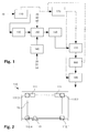
- the FIG. 1 is a schematic block diagram of an inventive plant for the production of solar panels.
- the solar panel 1 (see. FIG. 5 ) comprises as the base substrate a substantially rectangular glass plate 10 made of toughened safety glass.
- the solar cells are connected by longitudinal connector 31 and cross connector 33 in a conventional manner electrically connected.
- the solar panel 1 is arranged (eg, fixed on a building roof) in such a way that the glass plate 10 faces the sun.
- the solar radiation passes through the glass plate 10 and the first transparent plastic layer 20 and strikes the embedded between the plastic layers 20, 40 solar cells 30, where an electrical voltage is generated.
- the glass plate 10 is first provided with two markers in a marking and measuring stations 110 and measured.
- the measurement data is transmitted to a central database 120, which is part of an investment control, and stored therein.
- the glass plate 10 is cleaned and prepared for the further process steps.
- the solar cells 30 are first connected to the longitudinal connectors 31 to strings, then the strands are interconnected by means of the cross connector 33.
- the layer system is placed stepwise onto the glass plate 10, ie a first plastic film of EVA to form the first plastic layer 20, the interconnected solar cells 30 together with longitudinal and transverse connectors 31, 33, a second plastic film to form the second plastic layer 40 and the backsheet 50 are placed on the glass plate 10.
- laminating the module occurs in a laminator 160 Negative pressure and approx. 150 ° C.
- laminating form from the previously milky EVA plastic films clear, three-dimensionally crosslinked and no longer meltable plastic layers 20, 40, in which the solar cells 30 and the connectors are now embedded and firmly connected with each other and with the glass plate 10 and the backsheet 50 are.
- the EVA layers swell slightly over the outer edge of the glass plate 10 to the outside.
- the edges are lined in a cutting station 170, then in the next station 180, the contact areas of the cross connector 33 are exposed and finally in a further station 190, a junction box is set.
- the solar panel 1 can still be framed and measured and classified and packaged according to its electrical values.
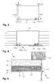
- the FIG. 2 is a schematic representation of the marking and measuring station 110.
- This comprises a support on which the glass plate 10 can be placed and holding devices 111 for holding the glass plate 10.
- Four cameras 112.1 ... 112.4 are arranged at the marking and measuring station 110, that their recording fields can capture the four corner regions of the glass plate 10.
- a marking head 113 along the longitudinal side of the glass plate 10 is arranged linearly movable.
- the method UniColor® from boraglas GmbH (see above) is used.
- the donor medium is first applied to the glass surface at the appropriate locations, for. B. glued as a film, after which by means of a laser housed in the marking head 113 laser to be marked areas are heated locally. Under the influence of the laser radiation, a glassy layer with silver nanoparticles is formed on the glass surface.
- FIG. 3 is a schematic representation of the generated marks. These include two placemarks 115.1, 115.2, each in the form of a cross, which have been produced in two corner regions of one of the longitudinal sides of the glass plate 10. Adjacent to the front placemark 115.1, a two-dimensional data matrix 116 has been applied to the glass surface in the same manner. It encodes a unique identification number for the glass plate 10. By the two placemarks 115.1, 115.2, a two-dimensional Cartesian coordinate system is defined, whose origin is given by the rear placemark 115.2. The x-axis extends from the origin through the front placemark 115.1, the y-axis is rotated counterclockwise by 90 ° to the x-axis. Each of the four corners P 1 ...
- P 4 detected by the cameras 112.1... 112.4 can be represented by an XY coordinate pair in this coordinate system. It should be noted that the x-axis does not necessarily have to run parallel to the longitudinal side of the glass plate 10, ie the placemarks 115.1, 115.2 need not be the same distance from the longitudinal side of the plate. It is for the functioning of the invention largely irrelevant where the two placemarks are mounted. In the sense of a good precision, it is advantageous if their distance is sufficiently large.
- the FIG. 4 is a schematic representation of the cutting station 170.
- This includes a turntable 171, on which the solar panel 1 can be placed.
- a turntable 171 On which the solar panel 1 can be placed, protrude portions of the backsheet (and optionally also the laminating layers) on the glass plate 10 out.
- Suction devices (not shown) hold the solar panel 1 on the support surface of the turntable 171 firmly.
- the turntable 171 allows in a conventional manner any rotational movements of the solar panel 1 and a transverse displacement of the same.
- a longitudinally displaceable cutting tool 172 is arranged on a longitudinal side of the turntable 171.
- the cutting station also has two cameras 175.1, 175.2, which are also arranged in the region of this longitudinal side and the distance is set so that they can detect the two placemarks 115.1, 115.2 and the data matrix 116.
- the front camera 175.1 simultaneously detects the front placemark 115.1 and the data matrix 116 arranged next to it in its recording field.
- FIG. 5 shows a schematic cross section through the cutting tool 172 and the processed edge region of the laminate 1.
- the cutting tool comprises a per se known, circular rotating cutting blade 173 and a support roller 174, which is supported on the axis of rotation of the cutting blade 173 opposite main side of the laminate 1.
- the cutting blade 173 is designed in such a way that sections of the backsheet 50 projecting beyond the glass plate 10 and of the laminating foils 20, 40 can be cut off.
- the Figures 6A-C serve to illustrate the method for cutting off the protruding edge region of the backsheet.
- the laminate 1 is first positioned on the turntable 171 so that the two placemarks 115.1, 115.2 and the data matrix 116 can be detected by the two cameras 175.1, 175.2 arranged at the cutting station 170.
- the one longitudinal side of the laminate 1 is thus approximately parallel to that edge of the support of the turntable 171, which is provided with the two cameras 175.1, 175.2 (see FIG. 6A ).
- the identification information read from the data matrix 116 is sent to the database, whereupon it returns the measurement data acquired to the plate 10 of the laminate 1 to the cutting station 170.
- the laminate 1 is then positioned on the basis of the obtained measurement data and the placemarks 115.1, 115.2 in such a way that the desired cutting line coincides with the travel path of the cutting tool 172.
- the cutting line has in the illustrated embodiment, a distance of 0.1 - 0.2 mm from the edge of the plate 10.
- the suction devices of the turntable 171 are activated, whereby the laminate 1 is securely held on the support of the turntable 171.
- the protruding portion of the backsheet and optionally the laminating films is separated, in the FIG. 6B is the result of this step.
- the laminate 1 is rotated by 90 ° and transversely displaced, so that a narrow side of the laminate 1 adjoins that edge of the support of the turntable 171 which is connected to the cameras 175.1 , 175.2 is provided.
- the positioning of the laminate 1 continues to take place on the basis of the acquired measurement data, however, a detection of the placemarks 115.1, 115.2 is no longer necessary in the further course, since the further positioning steps take place in each case relative to the previous position.
- the laminate 1 is again in a position such that the desired cutting line along the narrow side coincides with the travel of the cutting tool 172. Accordingly, by a linear movement of the cutting tool 172 again the protruding portion of the backsheet and optionally the laminating films are separated.
- a system according to the invention may comprise further stations, or individual stations may be missing.
- the geometry of the holding devices and transport devices for the glass plate or for the laminate as well as the number and arrangement of the cameras can be chosen differently.
- the position or the type of markings may be different, so different placemarks are conceivable, or the mark for identification is a barcode instead of a data matrix.
- the distance or angle values used and the corresponding coordinate system can also be chosen differently.
- combined distance and angle values may be used instead of the four data pairs in the Cartesian coordinate system, e.g. B. polar coordinates.
- the glass plate or the processing device can always be moved in each case.
- a processing device eg marking head, cutting device
- two opposing cutting devices may be provided which can simultaneously cut off protruding portions on two opposite sides of the laminate.
- the cutting device may also be structurally different.
- the invention provides a method and a plant which enable precise processing of laminates.
Abstract
Description
Die Erfindung betrifft ein Verfahren zum Bearbeiten eines Laminats, welches mindestens eine feste Platte, insbesondere eine Glasplatte, aufweist. Die Erfindung betrifft weiter eine Anlage zum Bearbeiten eines solchen Laminats.The invention relates to a method for processing a laminate, which has at least one fixed plate, in particular a glass plate. The invention further relates to a system for processing such a laminate.
Laminate haben einen weiten Anwendungsbereich und können sehr unterschiedliche Schichtsysteme aufweisen. Eine Gruppe von Laminaten weist eine oder mehrere feste Platten auf, welche dem Laminat Formstabilität verleihen. Als feste Platten dienen oft Glasplatten, insbesondere dann, wenn das Laminat ganz oder teilweise transparent sein soll. Beispiele für solche Laminate sind Verbundgläser, welche bei der Automobil- oder Gebäudeverglasung zum Einsatz kommen.Laminates have a wide range of applications and can have very different layer systems. One group of laminates has one or more solid plates which impart dimensional stability to the laminate. Glass plates are often used as solid plates, especially if the laminate is to be completely or partially transparent. Examples of such laminates are laminated glasses, which are used in automotive or building glazing.
Eine spezifische Anwendung solcher Laminate sind zudem Solarpanels (auch Solarmodule genannt). Es ist bekannt, solche Solarpanels aufzubauen, indem eine Mehrzahl von mechanisch empfindlichen Solarzellen (photovoltaische Zellen, z. B. Dickschicht-Solarzellen auf der Basis von Silicium) elektrisch miteinander verbunden und in einem Schichtsystem eingeschlossen werden. Das Schichtsystem verleiht mechanische Stabilität und schützt die eingeschlossenen Zellen vor Witterungseinflüssen oder mechanischen Beeinträchtigungen. Das Schichtsystem kann beispielsweise auf einem für die relevanten Anteile der Sonnenstrahlung transparenten Glassubstrat und einer Rückseitenfolie basieren, zwischen welchen die Solarzellen und die sie verbindenden elektrischen Verbinder eingeschlossen sind. Zwischen den genannten Schichten sind Folien aus EVA (Ethylenvinylacetat) oder einem anderen geeigneten Material eingebracht, so dass das Schichtsystem unter dem Einfluss von Wärme und Druck zusammenlaminiert werden kann. Die Solarzellen können von einem Rahmen umschlossen werden.A specific application of such laminates are also solar panels (also called solar modules). It is known to construct such solar panels by electrically connecting a plurality of mechanically sensitive solar cells (photovoltaic cells, eg silicon-based thick-film solar cells) and enclosing them in a layer system. The layer system provides mechanical stability and protects the enclosed cells from the effects of the weather or mechanical damage. The layer system may, for example, be based on a glass substrate transparent to the relevant portions of the solar radiation and a backsheet between which the solar cells and the electrical connectors connecting them are enclosed. Films of EVA (ethylene vinyl acetate) or other suitable material are incorporated between said layers so that the layer system can be laminated together under the influence of heat and pressure. The solar cells can be enclosed by a frame.
Bei der Herstellung derartiger Laminate ist es oft notwendig, über die feste Platte überstehende Abschnitte von Laminierschichten bzw. der Rückseitenfolie nach dem Laminieren abzutrennen. Dafür sind mehrere Verfahren bekannt:In the production of such laminates, it is often necessary to separate over the solid plate protruding portions of laminating or the backsheet after lamination. Several methods are known for this:
So beschreibt die
Das manuelle Abschneiden der Randbereiche ist allerdings zeitaufwendig und die Verletzungsgefahr für das Personal ist erheblich. Es gibt deshalb Ansätze, zum Abschneiden spezielle Werkzeuge einzusetzen, bzw. diesen Vorgang zu automatisieren:The manual cutting of the edge areas, however, is time consuming and the risk of injury to personnel is considerable. There are therefore approaches to using special tools to cut off, or to automate this process:
Die
Die
Die
Bei der Herstellung von festen Platten, insbesondere von Glasplatten, sind Grössentoleranzen im Bereich von 0.5 - 2 mm zu erwarten. Falls eine präzise Abtrennung der überstehenden Randbereiche erforderlich ist, muss das Abschneiden auf die Kante der jeweiligen Platte ausgerichtet werden. Bei all den erwähnten Verfahren kann sich nun aber das Problem stellen, dass die Kante der festen Platte nach der Lamination aufgrund der seitlich ausquellenden Laminierschichten, den verschiedenen Ausdehnungen der Schichten und/oder der Rückseitenfolie sowohl mechanisch als auch berührungsfrei nur noch schwer detektiert werden kann. Dies erschwert ein gleichmässiges Abschneiden des überstehenden Abschnitts in Bezug auf die feste Platte, insbesondere wenn das Abschneiden automatisiert erfolgen soll, und kann bei Kontakt des Schneidwerkzeugs mit der Platte (insbesondere mit gehärtetem Glas) zu übermässiger Abnutzung oder Beschädigung des Schneidwerkzeugs führen.Size tolerances in the range of 0.5 - 2 mm are to be expected in the production of solid plates, in particular of glass plates. If a precise separation of the protruding edge areas is required, the cutting must be aligned to the edge of the respective plate. In all of the mentioned methods, however, the problem can now arise that the edge of the solid plate after the lamination due to the laterally swelling Lamination, the different dimensions of the layers and / or the backsheet both mechanically and non-contact can be difficult to detect. This makes it difficult to uniformly cut off the projecting portion with respect to the fixed plate, particularly if the cutting is to be automated, and may result in excessive wear or damage to the cutting tool upon contact of the cutting tool with the plate (particularly tempered glass).
Dasselbe Problem stellt sich auch bei anderen Bearbeitungsvorgängen des laminierten Schichtsystems, welche in einem geometrischen Bezug zur Kante der festen Platte erfolgen sollen, z. B. wenn das Laminat mit einem Rahmen versehen werden soll oder wenn bestimmte Bauteile in vorgegebenen Abständen an- oder eingebaut werden sollen.The same problem arises in other processing operations of the laminated layer system, which are to take place in a geometric relation to the edge of the fixed plate, for. B. if the laminate is to be provided with a frame or if certain components to be installed or installed at predetermined intervals.
Aufgabe der Erfindung ist es, ein dem eingangs genannten technischen Gebiet zugehörendes Verfahren und eine entsprechende Anlage zu schaffen, welche eine präzise Bearbeitung von Laminaten ermöglichen.The object of the invention is to provide a method of the technical field mentioned above and a corresponding system, which allow precise processing of laminates.
Die Lösung der Aufgabe ist durch die Merkmale des Anspruchs 1 definiert. Gemäss der Erfindung wird vor dem Laminationsschritt mindestens eine Ortsmarkierung an der festen Platte angebracht, und es wird mindestens ein Abstands- und/oder Winkelwert der festen Platte in Bezug auf die Ortsmarkierung bestimmt. Nach dem Laminationsschritt wird das Laminat bearbeitet, wobei das Laminat und ein Bearbeitungswerkzeug in Abhängigkeit der Ortsmarkierung und des mindestens einen Abstands- und/oder Winkelwerts automatisch relativ zueinander positioniert werden.The solution of the problem is defined by the features of
Bei einem Abstandswert kann es sich beispielsweise um einen Abstand einer Kante bzw. einer Ecke von der Ortsmarkierung handeln. Die Werte können auch in einem Koordinationssystem gemessen werden, das durch die Ortsmarkierung bzw. mehrere Ortsmarkierungen definiert wird. Ein Winkelwert ergibt sich aus einem Winkel zwischen zwei Geraden, die durch die feste Platte und/oder die Ortsmarkierungen definiert sind oder sich aus dem Koordinatensystem ergeben.For example, a distance value may be a distance of an edge or a corner from the placemark. The values can also be measured in a coordination system defined by the placemark or multiple placemarks. An angle value results from an angle between two straight lines which are defined by the fixed plate and / or the location marks or which result from the coordinate system.
Vor der Lamination lässt sich die feste Platte ohne weiteres vermessen, ihre Kante ist sowohl mechanisch (z. B. durch einen Fühler) als auch berührungsfrei (z. B. optisch mittels einer Kamera) detektierbar, und es lassen sich gängige, insbesondere automatisierte Verfahren zur Vermessung einsetzen. Nach der Lamination ist die Erfassung der Kanten der festen Platte erschwert oder praktisch verunmöglicht. Nun kann aber im Rahmen der Erfindung die Bearbeitung gestützt auf die angebrachten Ortsmarkierungen und den erfassten Abstands- und/oder Winkelwert (bzw. eine Mehrzahl solcher Werte) erfolgen. Es ist somit nicht mehr notwendig, die Kante der festen Platte nach der Lamination noch zu detektieren.Before the lamination, the solid plate can be easily measured, its edge can be detected both mechanically (eg by a sensor) and non-contact (eg visually by means of a camera), and conventional, in particular automated, methods can be used to measure. After lamination, the detection of the edges of the solid plate is made difficult or virtually impossible. However, within the scope of the invention, the processing can be carried out based on the attached location marks and the detected distance and / or angle value (or a plurality of such values). It is thus no longer necessary to detect the edge of the solid plate after lamination.
Eine erfindungsgemässe Anlage zum Bearbeiten eines Laminats, welches mindestens eine feste Platte, insbesondere eine Glasplatte, aufweist, umfasst entsprechend
- a) eine Markierstation zum Anbringen einer Ortsmarkierung an der festen Platte;
- b) eine Messstation zum Bestimmen mindestens eines Abstands- und/oder Winkelwerts der festen Platte in Bezug auf die Ortsmarkierung;
- c) eine Laminierstation zum Laminieren des Laminats, welche der Markierstation und der Messstation nachgeordnet ist; und
- d) mindestens eine Bearbeitungsstation, welche der Laminierstation nachgeordnet ist, mit einem Bearbeitungswerkzeug, wobei das Bearbeitungswerkzeug und das Laminat in Abhängigkeit der Ortsmarkierung und des mindestens einen Abstands- und/oder Winkelwerts automatisch relativ zueinander positionierbar sind.
- a) a marking station for attaching a placemark on the fixed plate;
- b) a measuring station for determining at least one distance and / or angle value of the fixed plate with respect to the location mark;
- c) a laminating station for laminating the laminate downstream of the marking station and the measuring station; and
- d) at least one processing station, which is arranged downstream of the laminating station, with a processing tool, wherein the processing tool and the laminate are automatically positioned relative to each other depending on the placemark and the at least one distance and / or angle value.
Die Markierstation und die Messstation können konstruktiv in einer einzigen Station (Markier- und Messstation) integriert sein, es können aber auch zwei hintereinander angeordnete Stationen vorhanden sein.The marking station and the measuring station can be structurally integrated in a single station (marking and measuring station), but there may also be two stations arranged one behind the other.
Die Ortsmarkierung kann durch verschiedene (an sich bekannte) Verfahren aufgebracht werden. So ist es bekannt, Beschriftungen und Markierungen im Innern von Glassubstraten mittels fokussierter Laserstrahlung zu erzeugen (vgl.
Eine weitere Möglichkeit bietet der Tintenstrahldruck (Inkjet), eine etablierte Technologie zur Erzeugung von Markierungen auf Glas- und anderen festen Oberflächen. Im Rahmen des erfindungsgemässen Verfahrens besonders bevorzugt sind aber die unter den Markennamen MarcColor® bzw. UniColor® von der Firma boraglas GmbH, Halle (Deutschland) angebotenen Technologien, siehe auch
Weitere Technologien zur Markierung, wie z. B. das ortsgenaue Aufbringen eines Aufklebers, sind im Rahmen der Erfindung ebenfalls einsetzbar. Neben optisch lesbaren Markierungen, die eine besonders hohe Positionsgenauigkeit ermöglichen, sind auch beispielsweise induktiv oder kapazitiv erfassbare Markierungen denkbar.Other marking technologies, such as: As the exact location applying a sticker, are also used in the invention. In addition to optically readable markings, which allow a particularly high position accuracy, for example, inductive or capacitive detectable markings are conceivable.
Bevorzugt werden an der festen Platte zwei voneinander distanzierte Ortsmarkierungen angebracht, so dass auf deren Basis sowohl die Positionierung als auch die Orientierung der festen Platte stets eindeutig ermittelbar ist.Preferably, two mutually distanced placemarks are attached to the fixed plate, so that on the basis of both the positioning and the orientation of the fixed plate is always clearly determined.
Um die zwei (oder mehr) Ortsmarkierungen anzubringen, kann die Markierstation einen beweglich angeordneten Markierkopf umfassen, der sich an die entsprechenden Positionen bewegen lässt.To attach the two (or more) placemarks, the marking station may include a movably arranged marking head that can be moved to the appropriate positions.
Alternativ wird die zu markierende Platte relativ zu einer Markiervorrichtung bewegt.Alternatively, the plate to be marked is moved relative to a marking device.
Das erfindungsgemässe Verfahren eignet sich besonders zum Abtrennen eines überstehenden Abschnitts einer Schicht des Laminats, insbesondere einer Rückseitenfolie, wobei im Rahmen des Bearbeitungsschritts das Laminat und ein Trennwerkzeug zum Abtrennen des überstehenden Abschnitts in Abhängigkeit der Ortsmarkierung und des mindestens einen Abstands- und/oder Winkelwerts automatisch relativ zueinander positioniert werden.The inventive method is particularly suitable for separating a projecting portion of a layer of the laminate, in particular a backsheet, wherein in the processing step, the laminate and a cutting tool for separating the protruding portion depending on the placemark and the at least one distance and / or angle automatically be positioned relative to each other.
Das Abtrennen der Rückseitenfolie (welche z. B. aus Polyester oder Polyvinylfluorid hergestellt ist) stellt dabei andere Anforderungen als das Abtrennen von zwischen zwei Glasplatten (und allenfalls weiteren Schichten) eingeschlossenen Laminat-Zwischenschichten.The separation of the backsheet (which is made of polyester or polyvinyl fluoride, for example) has different requirements than the separation of intermediate laminate layers enclosed between two glass plates (and possibly further layers).
Dazu ist die Bearbeitungsstation als Schneidstation ausgebildet und umfasst ein Trennwerkzeug zum Abtrennen des überstehenden Abschnitts. Das Laminat und das Trennwerkzeug sind in Abhängigkeit der Ortsmarkierung und des mindestens einen Abstands- und/oder Winkelwerts automatisch relativ zueinander positionierbar. Dabei kann das Schneidwerkzeug beweglich ausgebildet sein und/oder die Schneidstation umfasst eine bewegliche Halteeinrichtung für das Laminat.For this purpose, the processing station is designed as a cutting station and comprises a separating tool for separating the projecting portion. The laminate and the separating tool can be automatically positioned relative to one another depending on the location marking and the at least one distance and / or angle value. In this case, the cutting tool can be designed to be movable and / or the cutting station comprises a movable holding device for the laminate.
Bei einer bevorzugten Ausführungsform der Schneidstation umfasst das Trennwerkzeug ein rotierendes Schneidmesser. Dieses wird für den Schneidvorgang derart in Rotation versetzt, dass seine Umfangsgeschwindigkeit grösser ist als die Relativgeschwindigkeit zwischen Laminat und Trennwerkzeug. Das Schneidmesser kann mit einer Stützrolle zusammenwirken, die auf der gegenüberliegenden Seite des Laminats aufliegt. Eine seitliche Abstützung des Trennwerkzeugs an der unregelmässigen Begrenzung des Laminats oder an der festen Platte ist nicht notwendig.In a preferred embodiment of the cutting station, the cutting tool comprises a rotating cutting blade. This is rotated for the cutting process in such a way that its peripheral speed is greater than the relative speed between the laminate and the cutting tool. The cutting blade may cooperate with a support roller which rests on the opposite side of the laminate. A lateral support of the cutting tool on the irregular boundary of the laminate or on the fixed plate is not necessary.
Alternativ sind andere Trennwerkzeuge einsetzbar, z. B. stationär am Trennwerkzeug angeordnete Schneidmesser oder Trennwerkzeuge, welche mit Wärme auf den abzutrennenden Abschnitt einwirken, z. B. mit Heizeinrichtungen versehene Messer oder Laserschneider.Alternatively, other separation tools can be used, for. B. stationary on the cutting tool arranged cutting blade or cutting tools, which act with heat on the separated section, z. B. provided with heaters knife or laser cutter.
Neben dem Abtrennen des überstehenden Abschnitts können die erzeugten Markierungen und die ermittelten Winkel- und/oder Abstandswerte auch für weitere Bearbeitungsschritte heranzogen werden, z. B. zum Rahmen des Laminats oder zum ortsgenauen Anbringen von weiteren Elementen am Laminat.In addition to the separation of the protruding portion, the markings produced and the determined angle and / or distance values can also be used for further processing steps, for. B. to the frame of the laminate or for the accurate installation of other elements of the laminate.
Vorzugsweise wird im Rahmen des erfindungsgemässen Verfahrens eine weitere Markierung zur Identifikation des Laminats an der festen Platte angebracht. Dabei kann es sich insbesondere um eine datencodierende Markierung, z. B. einen Barcode oder eine zweidimensionale Datenmatrix, oder um eine Markierung in Klartext handeln. Diese kann der Platte einen (zumindest für den Verarbeitungsprozess) eindeutigen Identifikationscode zuordnen, durch welchen die Platte (und später das Laminat, in welchem die Platte aufgenommen ist) in späteren Schritten stets zweifelsfrei identifiziert werden kann. Die weitere Markierung wird mit Vorteil im gleichen Arbeitsgang aufgebracht wie die Ortsmarkierungen. Sie ist vorzugsweise optisch lesbar, es kann sich dabei aber auch beispielsweise um einen RFID-Tag handeln.Preferably, in the context of the method according to the invention, a further marking for identifying the laminate is applied to the fixed plate. This may in particular be a data-coding marking, z. A bar code or a two-dimensional data matrix, or to act a mark in plain text. This can assign to the plate a (at least for the processing process) unique identification code, by means of which the plate (and later the laminate in which the plate is accommodated) can always be unambiguously identified in later steps. The further marking is advantageously applied in the same operation as the placemarks. It is preferably optically readable, but it may also be an RFID tag, for example.
Alternativ wird auf eine derartige Markierung verzichtet und die Anlage zur Bearbeitung des Laminats umfasst ein System zum Verfolgen der Werkstücke, so dass beim späteren Bearbeitungsvorgang ermittelbar ist, um welches der vorher markierten und vermessenen Werkstück es sich handelt.Alternatively, such a marking is dispensed with and the system for processing the laminate comprises a system for tracing the workpieces, so that it can be determined during the subsequent processing operation as to which of the previously marked and measured workpiece is concerned.
Mit Vorteil wird der mindestens eine Abstand- und/oder Winkelwert nach seiner Bestimmung zusammen mit einer Identifikation des Laminats in einer zentralen Datenbank erfasst. Zum Bearbeiten des Laminats wird er dann wieder aus dieser zentralen Datenbank ausgelesen.Advantageously, the at least one distance and / or angle value is detected after its determination together with an identification of the laminate in a central database. To edit the laminate, it is then read out of this central database again.
Alternativ werden die ermittelten Messwerte direkt auf dem Laminat gespeichert, z. B. indem eine entsprechend codierte Markierung (z. B. eine zweidimensionale Datenmatrix) erzeugt wird oder mittels eines RFID-Tags. Die Messwerte können dann bei einer späteren Bearbeitungsstation direkt ausgelesen werden.Alternatively, the measured values obtained are stored directly on the laminate, for. By a correspondingly coded marking (eg a two-dimensional data matrix) is generated or by means of an RFID tag. The measured values can then be read out directly at a later processing station.
In einem bevorzugten Ausführungsbeispiel ist das Laminat im Wesentlichen rechteckig, und zur Bestimmung des mindestens eines Abstands- und/oder Winkelwerts wird eine Kamera eingesetzt, welche einen Eckbereich der festen Platte erfasst. Die Ecken einer rechteckigen Platte lassen sich in der Regel einfach erfassen, ihre Position bezüglich einer Markierung lässt sich durch zwei Zahlen eindeutig bestimmen, zudem kann auch der effektive Winkel bestimmt werden. Bei der Herstellung von Glasplatten sind die wellenartigen Abweichungen der Aussenkanten im Vergleich zu den weiteren Abweichungen von der exakten Rechteckform um mindestens eine Grössenordnung geringer. Durch die Positionen aller vier Ecken ist somit die Geometrie der Kontur des im Wesentlichen rechteckigen Laminats bis auf die untergeordneten wellenartigen Abweichungen eindeutig bestimmt. Bei der Verwendung einer Kamera ist es von Vorteil, wenn die Ortsmarkierungen derart im Eckbereich der Platte angeordnet sind, dass sowohl die Ecke der festen Platte als auch die jeweilige Ortsmarkierung gleichzeitig im Aufnahmefeld der Kamera sichtbar sind, so dass der entsprechende Abstands- und/oder Winkelwert aus einer einzigen Aufnahme bestimmt werden kann.In a preferred embodiment, the laminate is substantially rectangular, and to determine the at least one distance and / or angle value, a camera is used, which detects a corner region of the fixed plate. The corners of a rectangular plate are usually easy to capture, their position relative to a marker can be clearly determined by two numbers, and also the effective angle can be determined. In the production of glass plates, the wave-like deviations of the outer edges are smaller by at least an order of magnitude compared to the further deviations from the exact rectangular shape. As a result of the positions of all four corners, the geometry of the contour of the substantially rectangular laminate is thus uniquely determined except for the subordinate wave-like deviations. When using a camera, it is advantageous if the placemarks are arranged in the corner of the plate so that both the corner of the fixed plate and the respective placemat are simultaneously visible in the camera's recording field, so that the corresponding distance and / or Angle value can be determined from a single shot.
Eine präzise Bearbeitung des Laminats kann insbesondere erreicht werden, wenn bei der Bearbeitung eines flächigen Laminats, welches eine im Wesentlichen polygonale Form hat, eine Anzahl von Abstands- und/oder Winkelwerten bestimmt wird, die ausreicht, um eine polygonale Kontur des Laminats sowie einen Ortsbezug und eine Orientierung dieser Kontur zu mindestens zwei Ortsmarkierungen an der festen Platte eindeutig zu definieren. Wenn man die Welligkeit der Konturen (siehe oben) sowie Abweichungen in der dritten Dimension vernachlässigt, reichen beispielsweise bei einem viereckigen Laminat somit die Flächenkoordinaten der vier Eckpunkte in Bezug auf das von zwei Ortsmarkierungen aufgespannte (flächige) Koordinatensystem zur eindeutigen Definition der Viereckform aus.A precise processing of the laminate can be achieved, in particular, when a number of distance and / or angle values is determined during the processing of a laminar laminate which has a substantially polygonal shape, which is sufficient to form a polygonal contour of the laminate and a location reference and to uniquely define an orientation of this contour to at least two placemarks on the fixed platen. Neglecting the ripples of the contours (see above) as well as deviations in the third dimension, for example, in the case of a quadrangular laminate, the area coordinates of the four vertices with respect to the (two-dimensional) coordinate system spanned by two placemarks suffice to uniquely define the quadrangular shape.
Mit Vorteil umfasst somit die Messstation vier feste Kameras zum gleichzeitigen Ausmessen von vier Eckbereichen einer im Wesentlichen rechteckigen festen Platte. Steht eine solche Anzahl von Kameras zur Verfügung, erübrigen sich in der Messstation Relativbewegungen zwischen Platte und Erfassungseinrichtung. Die Erfassung kann somit präzise und schnell erfolgen. Einige oder alle Kameras können selbstverständlich beweglich in der Messstation angeordnet sein, so dass hintereinander verschieden grosse Laminate verarbeitbar sind. Um mit dieser Ausführungsform ein Laminat im Rahmen der erforderlichen Informationen vollständig zu vermessen, sind aber keine Bewegungen der Kameras oder der Platte notwendig.Advantageously, the measuring station thus comprises four fixed cameras for the simultaneous measurement of four corner regions of a substantially rectangular solid plate. If such a number of cameras are available, they are unnecessary in the measuring station Relative movements between plate and detection device. The detection can thus be precise and fast. Of course, some or all of the cameras can be movably arranged in the measuring station, so that successively different sized laminates can be processed. In order to completely measure a laminate within the scope of the required information with this embodiment, however, no movements of the cameras or of the plate are necessary.
Falls erforderlich, kann auch nach dem Laminationsschritt noch eine Positionsbestimmung am Laminat vorgenommen werden, insbesondere eine, bei welcher die Kante der festen Platte keine Rolle spielt. Die entsprechend bestimmte Position wird in Bezug auf die Ortsmarkierung an der festen Platte erfasst, und in einem nachfolgenden Bearbeitungsschritt werden das Laminat und das Bearbeitungswerkzeug in Abhängigkeit der Ortsmarkierung und der in Bezug auf die Ortsmarkierung erfassten Position relativ zueinander positioniert. In der als
Mit Vorteil umfasst die Bearbeitungsstation einen Drehtisch zur Aufnahme des Laminats, mit welchem eine Winkelkorrektur des Laminats in Abhängigkeit der Ortsmarkierung und des mindestens einen Abstands- und/oder Winkelwerts vornehmbar ist. Ein solcher Drehtisch ermöglicht eine einfache und schnelle Winkelkorrektur. Er kann zusätzlich mit Einrichtungen zur Quer- und/oder Längsverschiebung des Laminats sowie mit einer Haltevorrichtung für das Laminat (z. B. einer Unterdruckeinrichtung oder Klemmvorrichtungen) versehen sein.Advantageously, the processing station comprises a turntable for receiving the laminate, with which an angular correction of the laminate in dependence of the placemark and the at least one distance and / or angle value is vornehmbar. Such a turntable allows easy and quick angle correction. It can also be equipped with means for transverse and / or longitudinal displacement of the laminate and with a Holding device for the laminate (eg., A vacuum device or clamping devices) may be provided.
Mit Vorteil umfasst die Bearbeitungsstation mindestens eine Kamera zum Erfassen der Ortsmarkierung. Kameras sind kostengünstig und flexibel einsetzbar. Sie ermöglichen eine präzise Erfassung von optisch lesbaren Ortsmarkierungen. Falls beispielsweise zwei Ortsmarkierungen sowie eine Markierung zur Identifikation vorgesehen sind, kann eine einzige zu den verschiedenen Markierungen bewegbare Kamera vorhanden sein, oder es sind zwei während des Erfassungsprozesses feststehende Kameras vorhanden, und die Markierung zur Identifikation ist benachbart zu einer Ortsmarkierung angeordnet (bzw. dient gleichzeitig als Ortsmarkierung), damit eine der beiden Kameras die Ortsmarkierung und die Identifikation gleichzeitig erfassen kann.Advantageously, the processing station comprises at least one camera for detecting the placemark. Cameras are inexpensive and flexible in use. They allow a precise capture of optically readable placemarks. For example, if two placemarks and one tag are provided for identification, there may be a single camera movable to the different tags, or two fixed cameras during the capture process, and the tag for identification is located adjacent to a placemark at the same time as a placemark) so that one of the two cameras can simultaneously capture the placemark and the identification.
Aus der nachfolgenden Detailbeschreibung und der Gesamtheit der Patentansprüche ergeben sich weitere vorteilhafte Ausführungsformen und Merkmalskombinationen der Erfindung.From the following detailed description and the totality of the claims, further advantageous embodiments and feature combinations of the invention result.
Die zur Erläuterung des Ausführungsbeispiels verwendeten Zeichnungen zeigen:
- Fig. 1
- Eine schematische Blockdarstellung einer erfindungsgemässen Anlage zur Herstellung von Solarpanels;
- Fig. 2
- eine schematische Darstellung der Markier- und Messstation der Anlage;
- Fig. 3
- eine schematische Darstellung der erzeugten Markierungen;
- Fig. 4
- eine schematische Darstellung der Schneidstation der Anlage;
- Fig. 5
- einen schematischen Querschnitt durch das Schneidwerkzeug und die bearbeitete Randregion des Laminats; und
- Fig. 6A-C
- eine schematische Darstellung des Verfahrens zum Abschneiden des überstehenden Randbereichs der Rückseitenfolie.
- Fig. 1
- A schematic block diagram of an inventive plant for the production of solar panels;
- Fig. 2
- a schematic representation of the marking and measuring station of the system;
- Fig. 3
- a schematic representation of the generated markers;
- Fig. 4
- a schematic representation of the cutting station of the system;
- Fig. 5
- a schematic cross section through the cutting tool and the processed edge region of the laminate; and
- Fig. 6A-C
- a schematic representation of the method for cutting off the protruding edge region of the backsheet.
Die
Das Solarpanel 1 wird derart angeordnet (z. B. auf einem Gebäudedach befestigt), dass die Glasplatte 10 der Sonne zugewandt ist. Die Sonnenstrahlung tritt durch die Glasplatte 10 sowie die erste transparente Kunststoffschicht 20 hindurch und trifft auf die zwischen den Kunststoffschichten 20, 40 eingebetteten Solarzellen 30, wo eine elektrische Spannung erzeugt wird.The
Zur Fertigung des Solarpanels 1 wird die Glasplatte 10 in einer Markier- und Messstationen 110 zunächst mit zwei Ortsmarkierungen versehen und vermessen. Die Messdaten werden zu einer zentralen Datenbank 120, welche Teil einer Anlagesteuerung ist, übertragen und darin abgelegt. In einer weiteren Station 130 wird die Glasplatte 10 gereinigt und für die weiteren Verfahrensschritte vorbereitet. In einer weiteren Station 140 werden die Solarzellen 30 zunächst mit den Längsverbindern 31 zu Strängen verbunden, anschliessend werden die Stränge mittels der Querverbinder 33 zusammengeschaltet. Anschliessend wird in einer weiteren Station 150 das Schichtsystem schrittweise auf die Glasplatte 10 aufgelegt, d. h. eine erste Kunststofffolie aus EVA zur Bildung der ersten Kunststoffschicht 20, die zusammengeschalteten Solarzellen 30 mitsamt Längs- und Querverbindern 31, 33, eine zweite Kunststofffolie zur Bildung der zweiten Kunststoffschicht 40 und die Rückseitenfolie 50 werden auf die Glasplatte 10 gelegt. Als nächstes erfolgt in einer Laminationseinrichtung 160 das Laminieren des Moduls bei Unterdruck und ca. 150 °C. Beim Laminieren bilden sich aus den bis dahin milchigen EVA-Kunststofffolien klare, dreidimensional vernetzte und nicht mehr aufschmelzbare Kunststoffschichten 20, 40, in der die Solarzellen 30 und die Verbinder nun eingebettet sind und die fest untereinander sowie mit der Glasplatte 10 und der Rückseitenfolie 50 verbunden sind. Die EVA-Schichten quellen leicht über den Aussenrand der Glasplatte 10 nach aussen.To produce the
Nach dem Laminieren werden in einer Schneidstation 170 die Kanten gesäumt, anschliessend werden in der nächsten Station 180 die Kontaktbereiche der Querverbinder 33 freigelegt und schliesslich wird in einer weiteren Station 190 eine Anschlussdose gesetzt. In der Folge kann das Solarpanel 1 noch gerahmt und vermessen und nach seinen elektrischen Werten klassifiziert und verpackt werden.After lamination, the edges are lined in a cutting
Die
Zum Erzeugen der gewünschten Markierungen wird das Verfahren UniColor® der Firma boraglas GmbH (siehe oben) eingesetzt. Dazu wird zunächst an den entsprechenden Stellen das Spendermedium auf die Glasoberfläche aufgebracht, z. B. als Folie aufgeklebt, wonach mittels eines im Markierkopf 113 untergebrachten Lasers die zu markierenden Stellen lokal erwärmt werden. Unter dem Einfluss der Laserstrahlung entsteht eine glasartige Schicht mit Silbernanopartikeln auf der Glasoberfläche.To produce the desired markings, the method UniColor® from boraglas GmbH (see above) is used. For this purpose, the donor medium is first applied to the glass surface at the appropriate locations, for. B. glued as a film, after which by means of a laser housed in the marking
In der nachfolgenden Station 130 findet eine Reinigung der Glasplatte 10 statt, wodurch auch allenfalls im Rahmen des Markierens entstandene Verunreinigungen oder Schmauchspuren entfernt werden.In the
Die
Die
Die
Die
Als nächstes wird nun, nach der Deaktivierung der Saugvorrichtungen, mit Hilfe des Drehtischs 171 das Laminat 1 um 90° gedreht und in Querrichtung verschoben, so dass eine Schmalseite des Laminats 1 an denjenigen Rand der Auflage des Drehtischs 171 grenzt, welcher mit den Kameras 175.1, 175.2 versehen ist. Die Positionierung des Laminats 1 erfolgt weiterhin auf der Basis der erfassten Messdaten, eine Erfassung der Ortsmarkierungen 115.1, 115.2 ist jedoch im weiteren Verlauf nicht mehr notwendig, da die weiteren Positionierschritte jeweils relativ zur vorherigen Position erfolgen. Nach der erfolgten Positionierung befindet sich das Laminat 1 wieder in einer derartigen Position, dass sich die gewünschte Schnittlinie entlang der Schmalseite mit dem Verfahrweg des Schneidwerkzeugs 172 deckt. Entsprechend kann durch eine Linearbewegung des Schneidwerkzeugs 172 wiederum der überstehende Abschnitt der Rückseitenfolie und gegebenenfalls der Laminierfolien abgetrennt werden.Next, after deactivation of the suction devices, by means of the
Im weiteren Verlauf des Verfahrens (nicht dargestellt), erfolgen abermals zwei 90°-Drehungen des Laminats 1 gefolgt von entsprechenden Korrekturen der Querposition und dem Abschneidevorgang. Zuletzt wird das Laminat 1 wiederum um 90° gedreht, so dass es wieder seine Ausgangsposition auf dem Drehtisch 171 einnimmt und weiter befördert werden kann.In the further course of the process (not shown), two 90 ° turns of the
Die Erfindung ist nicht auf das dargestellte Ausführungsbeispiel beschränkt. So kann eine erfindungsgemässe Anlage weitere Stationen umfassen, oder einzelne der Stationen können fehlen. Die Geometrie der Haltevorrichtungen und Transportvorrichtungen für die Glasplatte bzw. für das Laminat sowie die Anzahl und Anordnung der Kameras können unterschiedlich gewählt werden. Entsprechend kann auch die Position oder die Art der Markierungen unterschiedlich sein, so sind andersartige Ortsmarkierungen denkbar, oder die Markierung zur Identifikation ist ein Barcode anstelle einer Datenmatrix. Die verwendeten Abstands- bzw. Winkelwerte und das entsprechende Koordinatensystem können ebenfalls anders gewählt werden. So können bei einer Abwandlung des Ausführungsbeispiels anstelle der vier Datenpaare im kartesischen Koordinatensystem beispielsweise kombinierte Abstands- und Winkelwerte verwendet werden, z. B. Polarkoordinaten.The invention is not limited to the illustrated embodiment. Thus, a system according to the invention may comprise further stations, or individual stations may be missing. The geometry of the holding devices and transport devices for the glass plate or for the laminate as well as the number and arrangement of the cameras can be chosen differently. Correspondingly, the position or the type of markings may be different, so different placemarks are conceivable, or the mark for identification is a barcode instead of a data matrix. The distance or angle values used and the corresponding coordinate system can also be chosen differently. Thus, in a modification of the embodiment, for example, combined distance and angle values may be used instead of the four data pairs in the Cartesian coordinate system, e.g. B. polar coordinates.
Bei Relativbewegungen zwischen der Glasplatte bzw. dem Laminat einerseits und einer Bearbeitungsvorrichtung (z. B. Markierkopf, Schneidvorrichtung) andererseits kann stets jeweils die Glasplatte oder die Bearbeitungsvorrichtung bewegt werden. Zur Beschleunigung des Abschneidevorangs können zwei einander gegenüberliegende Schneidvorrichtungen vorgesehen sein, die gleichzeitig überstehende Abschnitte auf zwei gegenüberliegenden Seiten des Laminats abtrennen können. Die Schneidvorrichtung kann zudem konstruktiv anders ausgebildet sein.In the case of relative movements between the glass plate or the laminate on the one hand and a processing device (eg marking head, cutting device) on the other hand, the glass plate or the processing device can always be moved in each case. To accelerate the Abschneidevorangs two opposing cutting devices may be provided which can simultaneously cut off protruding portions on two opposite sides of the laminate. The cutting device may also be structurally different.
Zusammenfassend ist festzustellen, dass durch die Erfindung ein Verfahren und eine Anlage geschaffen werden, welche eine präzise Bearbeitung von Laminaten ermöglichen.In summary, it should be noted that the invention provides a method and a plant which enable precise processing of laminates.
Claims (14)
Priority Applications (3)
| Application Number | Priority Date | Filing Date | Title |
|---|---|---|---|
| EP08405137A EP2119679A1 (en) | 2008-05-16 | 2008-05-16 | Method for processing a laminate |
| PCT/CH2009/000150 WO2009137950A1 (en) | 2008-05-16 | 2009-05-08 | Method for processing a laminate |
| US12/992,659 US20110119898A1 (en) | 2008-05-16 | 2009-05-08 | Method for machining a laminate |
Applications Claiming Priority (1)
| Application Number | Priority Date | Filing Date | Title |
|---|---|---|---|
| EP08405137A EP2119679A1 (en) | 2008-05-16 | 2008-05-16 | Method for processing a laminate |
Publications (1)
| Publication Number | Publication Date |
|---|---|
| EP2119679A1 true EP2119679A1 (en) | 2009-11-18 |
Family
ID=39760842
Family Applications (1)
| Application Number | Title | Priority Date | Filing Date |
|---|---|---|---|
| EP08405137A Withdrawn EP2119679A1 (en) | 2008-05-16 | 2008-05-16 | Method for processing a laminate |
Country Status (3)
| Country | Link |
|---|---|
| US (1) | US20110119898A1 (en) |
| EP (1) | EP2119679A1 (en) |
| WO (1) | WO2009137950A1 (en) |
Cited By (4)
| Publication number | Priority date | Publication date | Assignee | Title |
|---|---|---|---|---|
| CN102189338A (en) * | 2010-03-05 | 2011-09-21 | 帆宣系统科技股份有限公司 | Cutting method for equipment for cutting insulation line of periphery of solar panel |
| WO2011139934A1 (en) * | 2010-05-03 | 2011-11-10 | Corning Incorporated | Method for making a 3d glass article |
| ITTO20120779A1 (en) * | 2012-09-10 | 2014-03-11 | Biesse Spa | PROCEDURE FOR THE REMOVAL OF THE PORTION OF FILM DIRT FROM THE EDGES OF A LAMINATED GLASS SHEET |
| DE102014204176B4 (en) | 2014-03-07 | 2021-11-11 | Biesse S.P.A. | Method for removing the film section protruding over the edges of a laminated safety glass panel |
Families Citing this family (7)
| Publication number | Priority date | Publication date | Assignee | Title |
|---|---|---|---|---|
| US20110220624A1 (en) * | 2010-03-10 | 2011-09-15 | Marketech International Corp. | Method for use of a device for cutting the peripheral isolation lines of solar panels |
| DE202012101120U1 (en) | 2012-03-29 | 2013-07-16 | Kuka Systems Gmbh | processing device |
| DE102016123865A1 (en) * | 2016-12-08 | 2018-06-14 | Schott Ag | Process for the further processing of a glass tube semifinished product including a thermal deformation |
| DE102016124833A1 (en) | 2016-12-19 | 2018-06-21 | Schott Ag | Method for producing a hollow glass product from a glass tube semifinished product with markings, as well as uses thereof |
| IT201900023367A1 (en) * | 2019-12-09 | 2021-06-09 | Bottero Spa | FORMING METHOD AND PLANT FOR THE REALIZATION OF A LAMINATED GLASS SHEET |
| IT201900023394A1 (en) * | 2019-12-09 | 2021-06-09 | Bottero Spa | FORMING METHOD AND TRIMMING MACHINE FOR THE FORMING OF A LAMINATED GLASS SEMI-FINISHED PRODUCT FOR THE CREATION OF A LAMINATED GLASS SHEET |
| CN112248606B (en) * | 2020-09-27 | 2023-05-23 | 深圳双十科技有限公司 | Internal height measurement assembly and height measurement method of OCR laminating machine |
Citations (11)
| Publication number | Priority date | Publication date | Assignee | Title |
|---|---|---|---|---|
| US4067764A (en) | 1977-03-15 | 1978-01-10 | Sierracin Corporation | Method of manufacture of solar cell panel |
| DE3428547C2 (en) | 1983-08-02 | 1987-04-16 | Central Glass Co., Ltd., Ube, Yamaguchi, Jp | |
| DE19521022A1 (en) * | 1995-06-13 | 1996-12-19 | Heraeus Gmbh W C | Process for producing a layered composite |
| EP0845440B1 (en) | 1996-11-29 | 2002-03-06 | Central Glass Company, Limited | Apparatus for cutting the peripheral portion of a film projecting form the peripheral edge of a laminated glass plate |
| EP0861813B1 (en) | 1997-02-28 | 2002-06-05 | BOTTERO S.p.A. | A cutting assembly for trimming at least one flexible layer used to cover at least one sheet |
| JP2004083321A (en) * | 2002-08-26 | 2004-03-18 | Nippon Sheet Glass Co Ltd | Method and apparatus for cutting sheet-like body |
| DE10328617A1 (en) * | 2003-06-25 | 2005-01-13 | Hegla Fahrzeug- Und Maschinenbau Gmbh & Co Kg | Method and device for marking flat glass panes |
| EP1728770A2 (en) | 2005-06-03 | 2006-12-06 | Boraglas GmbH | Process for marking the surface of articles |
| WO2007031151A1 (en) | 2005-09-12 | 2007-03-22 | Boraglas Gmbh | Method for production of coloured structures in glass and glass produced thereby |
| WO2007062860A1 (en) | 2005-12-02 | 2007-06-07 | Boraglas Gmbh | Method for marking single pane security glass |
| US20080011802A1 (en) * | 2006-07-14 | 2008-01-17 | Innolux Display Corp. | Cutting system for master liquid crystal panel having different alignment marks and method for cutting master liquid crystal panel |
Family Cites Families (44)
| Publication number | Priority date | Publication date | Assignee | Title |
|---|---|---|---|---|
| US2078386A (en) * | 1935-11-29 | 1937-04-27 | Michael B Kendis | Glass cutting mechanism |
| US2515445A (en) * | 1947-05-07 | 1950-07-18 | Dearborn Glass Company | Glass cutting machine |
| US2538901A (en) * | 1949-07-02 | 1951-01-23 | Red Devil Tools | Apparatus for cutting plate glass |
| US3424357A (en) * | 1966-07-28 | 1969-01-28 | Ppg Industries Inc | Automatically sizing and severing glass sheets |
| FR1572186A (en) * | 1967-12-12 | 1969-06-27 | ||
| US3663333A (en) * | 1969-07-18 | 1972-05-16 | Fabreeka Products Co | Method of bonding material having a low coefficient of friction to a substrate |
| CH643478A5 (en) * | 1980-04-14 | 1984-06-15 | Erwin Jenkner | Trimming FOR PLATTENFOERMIGE WORKPIECES WITH ABOUT RELATED SKINS. |
| DE3544251A1 (en) * | 1985-12-14 | 1987-06-19 | Duerkopp System Technik Gmbh | METHOD AND DEVICE FOR THE AUTOMATIC CUTTING OF PARTS FROM FLAT AREA SEWING MATERIAL, ACCORDING TO DIFFERENT CONTOURS, TEMPLATES ON A COORDINATE CUTTING MACHINE |
| FR2607444B1 (en) * | 1986-12-02 | 1989-02-10 | Saint Gobain Vitrage | DEVICE FOR CUTTING PLASTIC SHEETS |
| US5244525A (en) * | 1987-11-02 | 1993-09-14 | Kimberly-Clark Corporation | Methods for bonding, cutting and printing polymeric materials using xerographic printing of IR absorbing material |
| DE3920671A1 (en) * | 1988-06-27 | 1989-12-28 | Central Glass Co Ltd | DEVICE AND METHOD FOR CUTTING OFF AN EXTENDING EDGE SECTION OF AN INTERLAYER IN A MULTILAYER GLASS |
| AT396085B (en) * | 1990-07-13 | 1993-05-25 | Gfm Fertigungstechnik | DEVICE FOR TRIMMING SPATIAL MOLDINGS FROM PLASTIC OD. DGL. |
| JPH0783992B2 (en) * | 1991-11-25 | 1995-09-13 | 池田物産株式会社 | Terminal treatment method for molded ceiling |
| JPH05345365A (en) * | 1992-06-15 | 1993-12-27 | Sumitomo Bakelite Co Ltd | Production of laminated sheet |
| ES2126115T3 (en) * | 1993-06-11 | 1999-03-16 | Isovolta | PROCEDURE FOR THE MANUFACTURE OF PHOTOVOLTAIC MODULES, AS WELL AS A DEVICE TO CARRY OUT THIS PROCEDURE. |
| US5727913A (en) * | 1996-05-24 | 1998-03-17 | Naim; Moshe | Double edge trimming tool |
| US6119565A (en) * | 1997-06-13 | 2000-09-19 | Jere M. L'Heureux | Apparatus and method for electronically measuring and cutting floor coverings |
| JP4354029B2 (en) * | 1998-09-04 | 2009-10-28 | 日清紡ホールディングス株式会社 | Conveying device in laminating equipment |
| JP3098003B2 (en) * | 1998-09-24 | 2000-10-10 | 日清紡績株式会社 | Laminating equipment for solar cells |
| US6567116B1 (en) * | 1998-11-20 | 2003-05-20 | James A. Aman | Multiple object tracking system |
| JP3065309B1 (en) * | 1999-03-11 | 2000-07-17 | 沖電気工業株式会社 | Method for manufacturing semiconductor device |
| DE60034840T3 (en) * | 1999-03-23 | 2011-02-24 | Kaneka Corp., Osaka-shi | Photovoltaic module |
| US6539830B1 (en) * | 1999-10-13 | 2003-04-01 | The Koskovich Company | Automated board processing apparatus |
| US7055418B2 (en) * | 2000-04-06 | 2006-06-06 | Fotoba International S.R.L. | Device for trimming and automatic cutting of images on paper and other graphic and photographic substrates, in particular of large size |
| JP2002036177A (en) * | 2000-05-26 | 2002-02-05 | Gerber Technol Inc | Device and method for cutting out combination of sheet members |
| GB0114834D0 (en) * | 2001-06-18 | 2001-08-08 | Statefresh Ltd | A method of and apparatus for affixing backing to plates |
| US20030041959A1 (en) * | 2001-08-14 | 2003-03-06 | Moosey Cynthia M. | Pattern for glass cutting and method for using the pattern |
| JP2004139035A (en) * | 2002-09-25 | 2004-05-13 | Seiko Epson Corp | Lens with infrared cut-off filter and method for manufacturing the same, and miniature camera |
| WO2005024760A1 (en) * | 2003-09-05 | 2005-03-17 | Toshiba Matsushita Display Technology Co., Ltd. | Method of manufacturing display device |
| DE102004030411A1 (en) * | 2004-06-23 | 2006-01-19 | Kuraray Specialities Europe Gmbh | Solar module as laminated safety glass |
| CA2504266C (en) * | 2005-04-14 | 2013-08-13 | Relizon Canada Inc. | Method and system for manufacturing label kits comprised of carrier sheets having labels of specific shape removably retained thereon |
| JP5058451B2 (en) * | 2005-06-02 | 2012-10-24 | コーニングジャパン株式会社 | Sheet material cutting unit, cutting device having this cutting unit, and cutting equipment having this cutting device |
| DE102005027964A1 (en) * | 2005-06-16 | 2006-12-28 | Peter Lisec | Method and device for removing the plastic film supernatant in laminated glass plates |
| CN102275041A (en) * | 2005-07-06 | 2011-12-14 | 三星钻石工业股份有限公司 | Manufacturing method of scribing wheel for brittle material |
| BRPI0520815B1 (en) * | 2005-12-29 | 2016-12-20 | Airbus España S L | process and tools for manufacturing composite ring structures |
| WO2007103168A2 (en) * | 2006-03-01 | 2007-09-13 | Lion Brothers Company, Inc. | Digital printed applique emblem |
| JP2007277032A (en) * | 2006-04-05 | 2007-10-25 | Alps Engineering Co Ltd | Glass panel cutting apparatus |
| US20080017304A1 (en) * | 2006-07-21 | 2008-01-24 | Dow Global Technologies Inc. | Parts with edges of plastic and fabric and processes for their production |
| JP2008069063A (en) * | 2006-09-15 | 2008-03-27 | Alps Engineering Co Ltd | Glass panel cutting apparatus |
| JP5492375B2 (en) * | 2007-09-25 | 2014-05-14 | 株式会社シライテック | Glass substrate cutting device |
| DE102008031061A1 (en) * | 2008-07-01 | 2011-01-05 | Grenzebach Maschinenbau Gmbh | Method and device for trimming photovoltaic modules |
| EP2174784A1 (en) * | 2008-10-13 | 2010-04-14 | 3S Swiss Solar Systems AG | Procedure to remove a projecting section of a laminate layer |
| JP5868122B2 (en) * | 2011-10-31 | 2016-02-24 | Jukiオートメーションシステムズ株式会社 | Substrate processing apparatus, table mechanism, positioning method and program |
| US20140028162A1 (en) * | 2012-07-26 | 2014-01-30 | Michelle Lynn Carlson | Case for portable electronic device |
-
2008
- 2008-05-16 EP EP08405137A patent/EP2119679A1/en not_active Withdrawn
-
2009
- 2009-05-08 WO PCT/CH2009/000150 patent/WO2009137950A1/en active Application Filing
- 2009-05-08 US US12/992,659 patent/US20110119898A1/en not_active Abandoned
Patent Citations (11)
| Publication number | Priority date | Publication date | Assignee | Title |
|---|---|---|---|---|
| US4067764A (en) | 1977-03-15 | 1978-01-10 | Sierracin Corporation | Method of manufacture of solar cell panel |
| DE3428547C2 (en) | 1983-08-02 | 1987-04-16 | Central Glass Co., Ltd., Ube, Yamaguchi, Jp | |
| DE19521022A1 (en) * | 1995-06-13 | 1996-12-19 | Heraeus Gmbh W C | Process for producing a layered composite |
| EP0845440B1 (en) | 1996-11-29 | 2002-03-06 | Central Glass Company, Limited | Apparatus for cutting the peripheral portion of a film projecting form the peripheral edge of a laminated glass plate |
| EP0861813B1 (en) | 1997-02-28 | 2002-06-05 | BOTTERO S.p.A. | A cutting assembly for trimming at least one flexible layer used to cover at least one sheet |
| JP2004083321A (en) * | 2002-08-26 | 2004-03-18 | Nippon Sheet Glass Co Ltd | Method and apparatus for cutting sheet-like body |
| DE10328617A1 (en) * | 2003-06-25 | 2005-01-13 | Hegla Fahrzeug- Und Maschinenbau Gmbh & Co Kg | Method and device for marking flat glass panes |
| EP1728770A2 (en) | 2005-06-03 | 2006-12-06 | Boraglas GmbH | Process for marking the surface of articles |
| WO2007031151A1 (en) | 2005-09-12 | 2007-03-22 | Boraglas Gmbh | Method for production of coloured structures in glass and glass produced thereby |
| WO2007062860A1 (en) | 2005-12-02 | 2007-06-07 | Boraglas Gmbh | Method for marking single pane security glass |
| US20080011802A1 (en) * | 2006-07-14 | 2008-01-17 | Innolux Display Corp. | Cutting system for master liquid crystal panel having different alignment marks and method for cutting master liquid crystal panel |
Non-Patent Citations (1)
| Title |
|---|
| LENK, A.; MORGENTHAL, L., DAMAGE-FREE MICROMARKING OF GLASS. GLASTECHN. BER. GLASS SCI. TECHNOL., vol. 73, no. 9, 2000, pages 285 - 289 |
Cited By (7)
| Publication number | Priority date | Publication date | Assignee | Title |
|---|---|---|---|---|
| CN102189338A (en) * | 2010-03-05 | 2011-09-21 | 帆宣系统科技股份有限公司 | Cutting method for equipment for cutting insulation line of periphery of solar panel |
| WO2011139934A1 (en) * | 2010-05-03 | 2011-11-10 | Corning Incorporated | Method for making a 3d glass article |
| CN102883856A (en) * | 2010-05-03 | 2013-01-16 | 康宁股份有限公司 | Method for making a 3D glass article |
| US8713968B2 (en) | 2010-05-03 | 2014-05-06 | Corning Incorporated | Method and apparatus for making a 3D glass article |
| CN102883856B (en) * | 2010-05-03 | 2016-05-25 | 康宁股份有限公司 | Manufacture the method for 3D glassware |
| ITTO20120779A1 (en) * | 2012-09-10 | 2014-03-11 | Biesse Spa | PROCEDURE FOR THE REMOVAL OF THE PORTION OF FILM DIRT FROM THE EDGES OF A LAMINATED GLASS SHEET |
| DE102014204176B4 (en) | 2014-03-07 | 2021-11-11 | Biesse S.P.A. | Method for removing the film section protruding over the edges of a laminated safety glass panel |
Also Published As
| Publication number | Publication date |
|---|---|
| US20110119898A1 (en) | 2011-05-26 |
| WO2009137950A1 (en) | 2009-11-19 |
Similar Documents
| Publication | Publication Date | Title |
|---|---|---|
| EP2119679A1 (en) | Method for processing a laminate | |
| EP3095075B1 (en) | Method and device for machining a substrate | |
| EP2180981B1 (en) | Robot tool, robot system and method for machining workpieces | |
| EP1880790B1 (en) | Facility for structuring solar modules | |
| DE102006035031B4 (en) | Method for processing a semiconductor wafer | |
| EP2174784A1 (en) | Procedure to remove a projecting section of a laminate layer | |
| EP2485867B1 (en) | Device and method for deblocking optical workpieces, particularly ophthalmic lenses | |
| EP1982808B1 (en) | Device for correcting flaws in a wooden workpiece | |
| DE102013104745B4 (en) | Method and device for producing a security document | |
| DE102009048442A1 (en) | Device and method for aligning workpieces | |
| DE102008021997B4 (en) | Beamsaw | |
| EP3372331B1 (en) | Method of dividing a panel-shaped workpiece | |
| EP1570927A1 (en) | Feeding device for a press brake with a lighting device | |
| DE202008008794U1 (en) | Device for trimming photovoltaic modules | |
| EP3754293B1 (en) | Method for measuring the format of a platelike workpiece | |
| DE202019102050U1 (en) | Marking system and laser cutting machine | |
| WO2004113242A1 (en) | Method and device for marking flat glass panes | |
| DE102017118761A1 (en) | Manufacturing cell and method for setting up a production cell | |
| DE102015119424A1 (en) | Method for processing at least one workpiece | |
| EP1741517B1 (en) | Vacuum clamping device for fixing a sheet and method for machining the sheet | |
| DE102016112268A1 (en) | Device and method for positioning a flat glass unit | |
| AT500076B1 (en) | DEVICE AND METHOD FOR APPLYING A SURFACE CONNECTOR TO A CONTACT AREA OF A WATER | |
| EP3636437A1 (en) | Method for attaching a printing plate on a cylinder, device for applying a printing plate on a cylinder, method for producing a printing plate, printing plate for use in a flexographic printing method and device for trimming the edges of a printing plate | |
| DE102016122355B4 (en) | Processing plant and method for processing a plate-shaped object | |
| DE102022207518A1 (en) | Method and device for positionally precise processing of a material web |
Legal Events
| Date | Code | Title | Description |
|---|---|---|---|
| PUAI | Public reference made under article 153(3) epc to a published international application that has entered the european phase |
Free format text: ORIGINAL CODE: 0009012 |
|
| AK | Designated contracting states |
Kind code of ref document: A1 Designated state(s): AT BE BG CH CY CZ DE DK EE ES FI FR GB GR HR HU IE IS IT LI LT LU LV MC MT NL NO PL PT RO SE SI SK TR |
|
| AX | Request for extension of the european patent |
Extension state: AL BA MK RS |
|
| AKX | Designation fees paid | ||
| REG | Reference to a national code |
Ref country code: DE Ref legal event code: 8566 |
|
| STAA | Information on the status of an ep patent application or granted ep patent |
Free format text: STATUS: THE APPLICATION IS DEEMED TO BE WITHDRAWN |
|
| 18D | Application deemed to be withdrawn |
Effective date: 20100519 |