EP2118564B1 - A combustion chamber for burning solid fuels - Google Patents
A combustion chamber for burning solid fuels Download PDFInfo
- Publication number
- EP2118564B1 EP2118564B1 EP08710145.7A EP08710145A EP2118564B1 EP 2118564 B1 EP2118564 B1 EP 2118564B1 EP 08710145 A EP08710145 A EP 08710145A EP 2118564 B1 EP2118564 B1 EP 2118564B1
- Authority
- EP
- European Patent Office
- Prior art keywords
- volatiles
- burning
- combustion chamber
- outlet
- combustion
- Prior art date
- Legal status (The legal status is an assumption and is not a legal conclusion. Google has not performed a legal analysis and makes no representation as to the accuracy of the status listed.)
- Not-in-force
Links
Images

Classifications
-
- F—MECHANICAL ENGINEERING; LIGHTING; HEATING; WEAPONS; BLASTING
- F23—COMBUSTION APPARATUS; COMBUSTION PROCESSES
- F23B—METHODS OR APPARATUS FOR COMBUSTION USING ONLY SOLID FUEL
- F23B60/00—Combustion apparatus in which the fuel burns essentially without moving
- F23B60/02—Combustion apparatus in which the fuel burns essentially without moving with combustion air supplied through a grate
-
- F—MECHANICAL ENGINEERING; LIGHTING; HEATING; WEAPONS; BLASTING
- F23—COMBUSTION APPARATUS; COMBUSTION PROCESSES
- F23B—METHODS OR APPARATUS FOR COMBUSTION USING ONLY SOLID FUEL
- F23B1/00—Combustion apparatus using only lump fuel
- F23B1/02—Combustion apparatus using only lump fuel for indirect heating of a medium in a vessel, e.g. for boiling water
- F23B1/08—Internal furnaces, i.e. with furnaces inside the vessel
-
- F—MECHANICAL ENGINEERING; LIGHTING; HEATING; WEAPONS; BLASTING
- F23—COMBUSTION APPARATUS; COMBUSTION PROCESSES
- F23B—METHODS OR APPARATUS FOR COMBUSTION USING ONLY SOLID FUEL
- F23B1/00—Combustion apparatus using only lump fuel
- F23B1/16—Combustion apparatus using only lump fuel the combustion apparatus being modified according to the form of grate or other fuel support
- F23B1/26—Combustion apparatus using only lump fuel the combustion apparatus being modified according to the form of grate or other fuel support using imperforate fuel supports
-
- F—MECHANICAL ENGINEERING; LIGHTING; HEATING; WEAPONS; BLASTING
- F23—COMBUSTION APPARATUS; COMBUSTION PROCESSES
- F23B—METHODS OR APPARATUS FOR COMBUSTION USING ONLY SOLID FUEL
- F23B1/00—Combustion apparatus using only lump fuel
- F23B1/30—Combustion apparatus using only lump fuel characterised by the form of combustion chamber
- F23B1/36—Combustion apparatus using only lump fuel characterised by the form of combustion chamber shaft-type
-
- F—MECHANICAL ENGINEERING; LIGHTING; HEATING; WEAPONS; BLASTING
- F23—COMBUSTION APPARATUS; COMBUSTION PROCESSES
- F23B—METHODS OR APPARATUS FOR COMBUSTION USING ONLY SOLID FUEL
- F23B10/00—Combustion apparatus characterised by the combination of two or more combustion chambers
- F23B10/02—Combustion apparatus characterised by the combination of two or more combustion chambers including separate secondary combustion chambers
-
- F—MECHANICAL ENGINEERING; LIGHTING; HEATING; WEAPONS; BLASTING
- F23—COMBUSTION APPARATUS; COMBUSTION PROCESSES
- F23B—METHODS OR APPARATUS FOR COMBUSTION USING ONLY SOLID FUEL
- F23B5/00—Combustion apparatus with arrangements for burning uncombusted material from primary combustion
- F23B5/04—Combustion apparatus with arrangements for burning uncombusted material from primary combustion in separate combustion chamber; on separate grate
-
- F—MECHANICAL ENGINEERING; LIGHTING; HEATING; WEAPONS; BLASTING
- F23—COMBUSTION APPARATUS; COMBUSTION PROCESSES
- F23B—METHODS OR APPARATUS FOR COMBUSTION USING ONLY SOLID FUEL
- F23B50/00—Combustion apparatus in which the fuel is fed into or through the combustion zone by gravity, e.g. from a fuel storage situated above the combustion zone
- F23B50/12—Combustion apparatus in which the fuel is fed into or through the combustion zone by gravity, e.g. from a fuel storage situated above the combustion zone the fuel being fed to the combustion zone by free fall or by sliding along inclined surfaces, e.g. from a conveyor terminating above the fuel bed
-
- F—MECHANICAL ENGINEERING; LIGHTING; HEATING; WEAPONS; BLASTING
- F23—COMBUSTION APPARATUS; COMBUSTION PROCESSES
- F23B—METHODS OR APPARATUS FOR COMBUSTION USING ONLY SOLID FUEL
- F23B80/00—Combustion apparatus characterised by means creating a distinct flow path for flue gases or for non-combusted gases given off by the fuel
- F23B80/04—Combustion apparatus characterised by means creating a distinct flow path for flue gases or for non-combusted gases given off by the fuel by means for guiding the flow of flue gases, e.g. baffles
-
- F—MECHANICAL ENGINEERING; LIGHTING; HEATING; WEAPONS; BLASTING
- F23—COMBUSTION APPARATUS; COMBUSTION PROCESSES
- F23L—SUPPLYING AIR OR NON-COMBUSTIBLE LIQUIDS OR GASES TO COMBUSTION APPARATUS IN GENERAL ; VALVES OR DAMPERS SPECIALLY ADAPTED FOR CONTROLLING AIR SUPPLY OR DRAUGHT IN COMBUSTION APPARATUS; INDUCING DRAUGHT IN COMBUSTION APPARATUS; TOPS FOR CHIMNEYS OR VENTILATING SHAFTS; TERMINALS FOR FLUES
- F23L9/00—Passages or apertures for delivering secondary air for completing combustion of fuel
- F23L9/04—Passages or apertures for delivering secondary air for completing combustion of fuel by discharging the air beyond the fire, i.e. nearer the smoke outlet
Definitions
- This invention relates to a combustion chamber for burning solid fuels having a volatiles content and, in particular, to a combustion chamber for burning solid fuels having a high volatiles content, and also to a fire chamber incorporating such a combustion chamber.
- solid fuels having a high volatiles content in this context is meant solid fuels such as wood pellets, pellets made from switchgrass, miscanthus, maize stalks, straw or the like, and nut shells such as almond shells, all collectively referred to as solid biomass fuels, and also fossil fuels such as peat or bituminous coal.
- solid biomass fuels such as wood pellets, pellets made from switchgrass, miscanthus, maize stalks, straw or the like
- nut shells such as almond shells
- fossil fuels such as peat or bituminous coal.
- an example of a low volatiles solid fuel would be anthracite coal.
- biomass fuels tends to burn inefficiently in conventional devices and this is due to its high volatiles content. Much of the heat is released into the burning gases (the flames) and is lost up the chimney or flue.
- a typical wood pellet stove includes a hopper, an auger, a firebox or grate, a combustion fan and a heat exchanger which, respectively, store, feed, burn the fuel and transfer the heat to the space to be heated.
- the auger operates in a timed manner to control the delivery of the pellet fuel from the hopper into the firebox.
- the rate of delivery of the fuel to the firebox is matched to the rate of consumption of the fuel for a particular output
- the combustion fan provides a measured amount of air to the firebox.
- An example of such a stove is the Pellet stove Mod. 1000 manufactured by Caminetti Montegrappa s.r.l of via A. da Bassano, 7/9,36020 Pove Del Grappa (VI), Italy.
- German Patent Publication No. DE 92 18 953 describes a pellet burning stove in which the pellets are burned in an open burner pan located at the base of a combustion chamber. Complete combustion of the pellets is achieved in the combustion chamber, and the hot exhaust gases exit through holes in the top of the combustion chamber and are directed through a heat exchanger to extract the heat therefrom.
- U.S. Patent Application Publication No. 2007/0089733 describes a wood-burning boiler having a combustion chamber with an air intake and an exhaust chamber connected to the combustion chamber for receiving burnt gases through an exhaust opening therein.
- the boiler includes first and second air preheat chambers from which secondary air is introduced into the combustion chamber through a plurality of holes.
- the exhaust chamber is positioned next to the second air preheat chamber such that in use heat from the exhaust gases is transferred to the air in the preheat chamber before the exhaust gases pass from the exhaust chamber into an exhaust passage where further heat is extracted by means of a water jacket surrounding the exhaust passage.
- U.S. Patent Application Publication No. 4233914 discloses a variable-output combustion chamber for burning solid fuels having a high volatiles content, the combustion chamber comprising an enclosed hollow body in which fuel is to be burnt, the body having a fuel inlet, a primary air inlet, a secondary air inlet and a burning volatiles outlet mounted therein wherein the burning volatiles outlet projects into another combustion chamber to consume the volatiles in suspension under supply of further combustion air. It is an object of the present invention to overcome the disadvantages of the devices hereinbefore described.
- the invention provides a variable-output combustion chamber for burning solid fuels having a high volatiles content, the combustion chamber comprising an enclosed hollow body in which the fuel is to be burnt, the body having a fuel inlet, a primary air inlet, a secondary air inlet and a burning volatiles outlet mounted therein, the burning volatiles outlet having a plurality of apertures for turbulating the confluence of burning volatiles and air of combustion as it exits therefrom, such that, in use, this confluence exits the outlet in a rapidly burning turbulent turbulent flow resulting in efficient combustion of the volatiles at all available outputs.
- An advantage of the combustion chamber according to the invention is that the volatiles have to exit the chamber via the apertures in the volatiles outlet and this causes an increase in the velocity of the burning volatiles as they exit. It also causes the turbulent flow of volatiles. The result is that the volatiles burn more efficiently and at a higher temperature than is achieved in a conventional device burning the same fuel. A consequence of this greater efficiency is that the levels of harmful products, such as the nitrous oxides, in the flue gases are reduced relative to known devices.
- a combustion chamber according to the invention can be used in devices such as boilers, air heaters and stoves, in hotplates, in devices for providing a source of heat for an industrial process, in an incinerator or the like.
- the apertures are of differing sizes.
- the apertures can be arranged in a particular pattern so as to optimise the performance of the combustion chamber in a particular application.
- the secondary air inlet is adjacent the burning volatiles outlet
- the positioning of the secondary air inlet can be important for a particular application of the combustion chamber and such positioning will affect the characteristics of the turbulent flow exiting from the volatiles outlet.
- the burning volatiles outlet has means for temporarily restricting the flow of burning volatiles therethrough.
- An advantage of the restricting means is that efficient combustion can be maintained at varying outputs. Thus, at low output the burning volatiles outlet can be restricted so as to maintain a turbulent flow of volatiles therethrough.
- upstanding formations on the outer surface of the body adjacent the apertures are shaped so as to direct the emerging burning volatiles along the outer surface.
- the body By diverting the burning volatiles along the outer surface of the body the body is maintained at a higher temperature which leads to more efficient combustion of the fuel. This is a requirement at low output particularly when the fuel has a relatively high moisture content.
- the primary air can also be preheated by the burning volatiles by passing the primary air supply duct through or against the burning volatiles.
- two or more burning volatiles outlets are mounted in the hollow body.
- This arrangement also lends itself to maximising the efficiency of the combustion chamber at all available outputs, while restricting the emission of oxides of nitrogen by reducing the peak temperature of combustion.
- a fire chamber for a device for burning solid fuels having a high volatiles content comprising a housing, a combustion chamber within the housing, the combustion chamber having an enclosed hollow body in which the fuel is to be burnt, the body having a fuel inlet, a primary air inlet, a secondary air inlet and a burning volatiles outlet mounted therein, the burning volatiles outlet having a plurality of apertures for turbulating the confluence of burning volatiles and air of combustion as it exits therefrom, such that, in use, this turbulated confluence exits the combustion chamber in a rapidly burning turbulent flow, the housing having an inner heat transferring surface shaped about the combustion chamber so as to define a channel therebetween, such that, in use, the turbulating confluence of burning volatiles and air of combustion exiting the burning volatiles outlet are forced to circulate around the combustion chamber within the channel in a turbulent flow resulting in efficient combustion of the volatiles.
- the fire chamber is heated more efficiently than a conventional fire chamber consuming a similar amount of fuel.
- An advantage of this arrangement is that the heat released by the volatiles is transferred both to the heat transferring surface and back into the combustion chamber. This provides a means for increasing the temperature of the zone into which the fresh fuel is introduced, particularly at low output, resulting in an increase in the overall temperature of combustion.
- a set of upstanding curved formations is mounted on the inner heat transferring surface around the combustion chamber within the channel.
- the shape and positioning of the set of upstanding curved formations within the channel further directs the circulation of the volatiles around the combustion chamber and also enhances the turbulent flow of the volatiles.
- the apertures are of differing sizes.
- the secondary air inlet is adjacent the burning volatiles outlet.
- the burning volatiles outlet has means for temporarily restricting the flow of burning volatiles therethrough.
- upstanding formations on the outer surface of the body adjacent the apertures are shaped so as to direct the emerging burning volatiles along the outer surface.
- two or more burning volatiles outlets are mounted in the hollow body.
- the tail of the flame emerging from each burning volatiles outlet will run into the flame emerging from the next burning volatiles outlet.
- This arrangement can provide a means for achieving complete combustion at the tail of each flame. It can also cause a reduction in the peak temperature of combustion, thereby preventing the formation and emission of nitrous oxides.
- the burning volatiles outlets are arranged equidistantly around the surface of the hollow body.
- the equidistant arrangement of the burning volatiles outlets optimises the flame merging effect described above.
- the burning volatiles outlets are positioned about the surface of the hollow body so as to facilitate the optimisation of the turbulent flow of burning volatiles thereabout for each output setting.
- means for moving the combustion chamber towards and away from the inner heat transferring surface is provided.
- An advantage of this arrangement is that when a low output is required the combustion chamber can be moved closer to the inner heat transferring surface. This has the effect of restricting the flow of volatiles through the burning volatiles outlet. Conversely, when a higher output is required the combustion chamber can be moved further away from the inner heat transferring surface.
- the combustion chamber is positioned at the top of the fire chamber, the burning volatiles outlet is mounted in the upper region of the combustion chamber, and an exhaust gases outlet is mounted in the housing below the combustion chamber, such that, in use, the burning volatiles, as they exit the burning volatiles outlet circulate around the top of the combustion chamber in the channel until they start to cool and consequently drop down in the channel, with the exhaust gases exiting the chamber through the exhaust gases outlet.
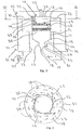
- a combustion chamber in accordance with the invention having an enclosed hollow body 11, which is generally circular in cross-section.
- the hollow body 11 has a cylindrical wall section 12, and a top section 13 at end 14 of the cylindrical wall section 12.
- the cylindrical wall section 12 narrows at end 15 to form a frusto-conical section 16, which terminates in a neck section 17, within which the ash collects in use to be removed through an exit pipe 18, which is regulated by a valve 19.
- a primary air inlet 20 is connected to the neck section 17 at point 21 and is regulated by a valve 22 housed therein.
- a fuel inlet 23 is mounted in the top section 13 at point 24 and in this embodiment the fuel inlet 23 also acts as a secondary air inlet.
- Each burning volatiles outlet 25 has a plurality of apertures 26 of differing sizes arranged in a plate 27.
- the plate 27 is made of tungsten to withstand the heat generated in use.
- a grate 28 is mounted within the hollow body 11 and supports the wood pellets 29 to be burnt. As the wood pellets 29 bum, they break up, fall through the grate 28 and are held on a mesh 30 while they burn for a further period, until they finally fall through the mesh 30 as ash (not shown), to be collected in the neck section 17.
- the combustion chamber 10 forms part of a fire chamber, shown generally at 31, in accordance with the invention.
- the fire chamber 31 has a water jacket 32 having a heat transfer surface 33 which encircles the combustion chamber 10.
- the heat transfer surface 33 is formed so as to create a channel 34 between the heat transfer surface 33 and the cylindrical section 12.
- the water jacket 32 has a water inlet 35 and a water outlet 36.
- the wood pellets 29 are introduced into the combustion chamber 10 through the fuel inlet 23 at a rate appropriate for the required heat output of the device.
- Primary air at the appropriate pressure is introduced into the combustion chamber 10 via the primary air inlet 20 and is blown up through the mesh 30, the grate 28 and the pellets 29.
- the primary combustion takes place above the grate 28 in the area of the top section 13.
- secondary air is introduced into the combustion chamber 10 through the fuel inlet 23 and mixes with the volatiles above the pellets 29.
- the burning volatiles then exit the combustion chamber 10 through the burning volatiles outlets 25 in a turbulent flow and circulate around the cylindrical section 12 raising the temperature of both the heat transfer surface 33 and the combustion chamber 10 itself.
- the burning of the volatiles is concentrated in the area above the pellets 29 and in the channel 34.
- the burning volatiles will remain in this area due to thermal buoyancy until they start to cool.
- the volatiles drop down in the combustion chamber 10 and the exhaust gases are vented through a flue 37, which is regulated by a paddle valve 38.
- FIG. 2 the arrangement of the volatiles outlets 25 around the cylindrical section 12 can be seen more clearly.
- the arrows 39 indicates the path of the turbulent flow of the volatiles through the channel 34 around the combustion chamber 10.
- the burning volatiles outlets 25 are offset in the cylindrical section 12 such that the turbulent flow of volatiles, as it exits the volatiles outlets 25 is already directed around the combustion chamber 10, as desired.
- FIG. 3 there is illustrated, generally at 40, a second embodiment of a combustion chamber in accordance with the invention.
- the combustion chamber 40 is designed to burn wood pellets and to provide a blown flame and is suitable for use as a replacement for an oil burner in an oil-fired heating boiler.
- the combustion chamber 40 has an enclosed hollow body 41, which has a generally circular cross-section and a domed top section 42.
- a frusto-conical section 43 extends laterally from the top section 42 and terminates in a volatiles outlet 44 having a plurality of apertures 45.
- a fuel inlet 46 is located at point 47 on the top section 42 and a primary air inlet 48 is located at point 49 on the body section 41.
- a secondary air inlet 50 is mounted in the frusto-conical section 43 and is positioned such that a secondary air nozzle 51 is located, within the hollow body 41, adjacent the volatiles outlet 44.
- a grate 52 is mounted within the hollow body 41 and supports the wood pellets 53 to be burnt.
- a drop-on umbrella shaped plate 54 is mounted centrally on the grate 52 at position 55 below the fuel inlet 46. In use, the drop-on plate 54 prevents the burning wood pellets 53 from being crushed by fresh pellets 53 dropping from the fuel inlet 46 and also helps to disperse the pellets 53 over the grate 52.
- the burning of the pellets 53 on the grate 52 results in burning volatiles above the grate 52.
- These volatiles mixed with the primary and secondary air are forced through the apertures 45 of the burning volatiles outlet 44 and exit as a rapidly burning turbulent flow, which can be directed onto a heat transferring surface within the fire chamber of the heating boiler.
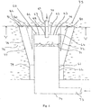
- FIG. 4 there illustrated generally at 60, a third embodiment of a combustion chamber in accordance with the invention, the combustion chamber 60 having an enclosed hollow body 61, which is generally circular in cross-section.
- the hollow body 61 has a cylindrical wall section 62 and a top section 63 at end 64 of the cylindrical section 62.
- a burning volatiles outlet 65 is mounted in the top section 63 and has a plurality of apertures 66 therein.
- a pipe 67 passes through a central opening 68 in the top section 63.
- the pipe 67 serves as a fuel inlet 69 and a secondary air inlet 70.
- a grate 71 is mounted within the hollow body 61 and supports the wood pellets 72 to be burnt.
- a primary air inlet 73 is mounted at the bottom end 74 of the hollow body 61.
- the combustion chamber 60 forms part of a fire chamber, shown generally at 75, in accordance with the invention.
- the fire chamber 75 has a water jacket 76 having an inner heat transferring surface 77 which encircles the combustion chamber 60.
- the inner heat transferring surface 77 has an upper section 78, which has an inverted frusto-conical shape and a lower cylindrical section 79.
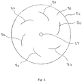
- a set of upstanding curved formations 80 is mounted on an internal surface 81 of a top section 82 of the inner heat transferring surface 77.
- the set of upstanding curved formations 80 is arranged equidistantly around the combustion chamber 60 and this can be more clearly seen with reference to Fig. 5 .
- a means (not shown) for moving the combustion chamber along its vertical axis is provided.
- the combustion chamber 60 can be moved closer to the top section 82 of the inner heat transferring surface 77. This has the effect of restricting the flow of volatiles through the volatiles outlet 65.
- the combustion chamber 60 can be moved further away from the top section 82 of the inner heat transferring surface 77.
- the wood pellets 71 are introduced into the combustion chamber 60 through the fuel inlet 69 at a rate appropriate for the required heat output of the device.
- Primary air at the appropriate pressure is introduced into the combustion chamber 60 via the primary air inlet 73 and is blown up through the grate 71 and the pellets 72.
- secondary air is introduced into the combustion chamber 60 through the secondary air inlet 70 and mixes with the volatiles above the pellets 72.
- the burning volatiles then exit the combustion chamber 60 through the burning volatiles outlet 65 in a turbulent flow and circulate around the fire chamber 75 raising the temperature of both the inner heat transferring surface 77 and the combustion chamber 60 itself.
- the shape and positioning of the set of upstanding curved formations 80 within the fire chamber 75 causes the volatiles to circulate around the combustion chamber 60 and also enhances the turbulent flow of the volatiles. As the volatiles cool they drop down to the end 74 of the combustion chamber 60, where they pass through an exit pipe (not shown).
Landscapes
- Engineering & Computer Science (AREA)
- Chemical & Material Sciences (AREA)
- Combustion & Propulsion (AREA)
- Mechanical Engineering (AREA)
- General Engineering & Computer Science (AREA)
- Physics & Mathematics (AREA)
- Thermal Sciences (AREA)
- Solid-Fuel Combustion (AREA)
Applications Claiming Priority (2)
| Application Number | Priority Date | Filing Date | Title |
|---|---|---|---|
| IE20070094A IE20070094A1 (en) | 2007-02-15 | 2007-02-15 | A combustion chamber for burning solid fuels |
| PCT/IE2008/000012 WO2008099373A1 (en) | 2007-02-15 | 2008-02-14 | A combustion chamber for burning solid fuels |
Publications (2)
| Publication Number | Publication Date |
|---|---|
| EP2118564A1 EP2118564A1 (en) | 2009-11-18 |
| EP2118564B1 true EP2118564B1 (en) | 2017-09-20 |
Family
ID=39620330
Family Applications (1)
| Application Number | Title | Priority Date | Filing Date |
|---|---|---|---|
| EP08710145.7A Not-in-force EP2118564B1 (en) | 2007-02-15 | 2008-02-14 | A combustion chamber for burning solid fuels |
Country Status (7)
| Country | Link |
|---|---|
| US (2) | US9310071B2 (zh) |
| EP (1) | EP2118564B1 (zh) |
| JP (1) | JP5637690B2 (zh) |
| CN (1) | CN101657680B (zh) |
| CA (1) | CA2677864C (zh) |
| IE (1) | IE20070094A1 (zh) |
| WO (1) | WO2008099373A1 (zh) |
Families Citing this family (16)
| Publication number | Priority date | Publication date | Assignee | Title |
|---|---|---|---|---|
| CN201539853U (zh) * | 2009-06-30 | 2010-08-04 | 王朝晖 | 一种燃料笼及具有该燃料笼的燃烧器 |
| CN102012038A (zh) * | 2010-06-30 | 2011-04-13 | 广州迪森热能技术股份有限公司 | 生物质成型燃料锅炉配风系统 |
| DE102011108637A1 (de) * | 2011-05-30 | 2015-08-13 | Robert Bosch Gmbh | Brenner für einen Biomasse-Brennstoffkessel und Biomasse-Brennstoffkessel |
| ES2432475B1 (es) * | 2012-05-31 | 2014-11-18 | Jose Enrique MORATALLA MARTINEZ | Caldera de biomasa para multiples combustibles |
| US11175047B2 (en) | 2014-12-05 | 2021-11-16 | Richard L. Hill | Pellet stove |
| US9845957B2 (en) * | 2014-12-05 | 2017-12-19 | Richard L. Hill | Pellet stove |
| US10674866B2 (en) | 2015-10-23 | 2020-06-09 | Traeger Pellet Grills Llc | Smoke generation cooking system and methods |
| US11765261B2 (en) | 2015-10-23 | 2023-09-19 | Traeger Pellet Grills, LLC. | Mobile application for controlling outdoor grill |
| US10791208B2 (en) | 2015-10-23 | 2020-09-29 | Traeger Pellet Grills, Llc | Mobile application for controlling outdoor grill |
| CN107251507A (zh) * | 2015-10-23 | 2017-10-13 | 特雷格佩列特烤架有限公司 | 用于控制户外烤架的移动应用 |
| US10455022B2 (en) | 2015-10-23 | 2019-10-22 | Traeger Pellet Grills, Llc | Cloud system for controlling outdoor grill with mobile application |
| CA3038229A1 (en) * | 2016-09-15 | 2018-03-22 | Pyroheat Ou | Pyrolysis boiler |
| HUP1700093A2 (en) * | 2017-03-02 | 2018-09-28 | Primus Net Kft | Pellet boiler with grid burner and proceedings of the combustion to maintain |
| CN107328099B (zh) * | 2017-08-17 | 2023-09-15 | 成都佳达农业科技发展有限公司 | 生物质热风炉以及全自动生物质热风炉 |
| CN108645022A (zh) * | 2018-05-10 | 2018-10-12 | 北京艺轩吉装饰工程有限公司 | 一种高效节能环保余热保温热水器 |
| CN113441533B (zh) * | 2021-07-30 | 2023-04-07 | 昆明理工大学 | 一种利用煤矸石加速废石成土方法 |
Family Cites Families (19)
| Publication number | Priority date | Publication date | Assignee | Title |
|---|---|---|---|---|
| US3543700A (en) * | 1969-07-07 | 1970-12-01 | Environmental Control Products | Air purifying incinerator apparatus |
| US3769922A (en) * | 1971-12-30 | 1973-11-06 | Combustion Power Inc | Fluid bed reactor pre-heating method and apparatus |
| US4233914A (en) * | 1978-10-02 | 1980-11-18 | Wellons, Inc. | Pressurized waste wood furnace system |
| US4375949A (en) * | 1978-10-03 | 1983-03-08 | Exxon Research And Engineering Co. | Method of at least partially burning a hydrocarbon and/or carbonaceous fuel |
| JPS608403B2 (ja) * | 1980-08-25 | 1985-03-02 | 元作 石塚 | 焼却炉 |
| JPS57204715A (en) * | 1981-06-11 | 1982-12-15 | Satake Eng Co Ltd | Combustion furnace for granular material |
| JPS5847090A (ja) * | 1981-09-17 | 1983-03-18 | Hayashi Seisakusho:Kk | 可燃ガス発生装置 |
| US4515093A (en) * | 1982-03-04 | 1985-05-07 | Beardmore David H | Method and apparatus for the recovery of hydrocarbons |
| US4565184A (en) * | 1984-05-17 | 1986-01-21 | Collins Bruce H | Combustible particulate fuel heater |
| DE59001568D1 (de) * | 1990-03-10 | 1993-07-01 | Krantz H Gmbh & Co | Vorrichtung zum verbrennen von in einem abluftstrom enthaltenen oxidierbaren bestandteilen. |
| DE4200721C2 (de) * | 1991-02-19 | 2002-11-28 | Riener Karl Stefan | Ofen für feste Brennstoffe, insbesondere für Pellets |
| DE9218953U1 (de) | 1991-02-19 | 1996-05-23 | Riener, Karl Stefan, Micheldorf | Ofen für feste Brennstoffe, insbesondere Pellets |
| US5178076A (en) * | 1991-09-06 | 1993-01-12 | Hand David J | Bio-mass burner construction |
| DE4215508C1 (en) | 1992-05-12 | 1993-05-27 | Georg Fischer Gmbh & Co Maschinen- U. Kesselfabrik, 8870 Guenzburg, De | Solid fuel heating boiler - has curved guide attached to grate reaching up beyond great plane and into bottom of combustion chamber |
| US5413089A (en) * | 1993-03-04 | 1995-05-09 | Harman Stove And Welding, Inc. | Wood and coal burning stove |
| CN2540568Y (zh) * | 2002-04-29 | 2003-03-19 | 顾廷路 | 气化燃煤炉 |
| US7438024B2 (en) * | 2005-10-20 | 2008-10-21 | Robert Bast | Wood-burning boiler |
| AT502684B1 (de) * | 2006-02-16 | 2007-05-15 | Freller Walter Ing | Vorrichtung zum verbrennen organischer stoffe |
| CA2656187A1 (en) | 2006-06-26 | 2008-01-03 | Koninklijke Philips Electronics N.V. | A solid fuel stove with improved combustion |
-
2007
- 2007-02-15 IE IE20070094A patent/IE20070094A1/en not_active IP Right Cessation
-
2008
- 2008-02-14 CN CN2008800095146A patent/CN101657680B/zh not_active Expired - Fee Related
- 2008-02-14 WO PCT/IE2008/000012 patent/WO2008099373A1/en active Application Filing
- 2008-02-14 JP JP2009549484A patent/JP5637690B2/ja not_active Expired - Fee Related
- 2008-02-14 EP EP08710145.7A patent/EP2118564B1/en not_active Not-in-force
- 2008-02-14 US US12/526,571 patent/US9310071B2/en not_active Expired - Fee Related
- 2008-02-14 CA CA2677864A patent/CA2677864C/en not_active Expired - Fee Related
-
2016
- 2016-03-04 US US15/061,072 patent/US20160238238A1/en not_active Abandoned
Non-Patent Citations (1)
| Title |
|---|
| None * |
Also Published As
| Publication number | Publication date |
|---|---|
| CA2677864A1 (en) | 2008-08-21 |
| JP2010519492A (ja) | 2010-06-03 |
| US9310071B2 (en) | 2016-04-12 |
| JP5637690B2 (ja) | 2014-12-10 |
| CN101657680B (zh) | 2012-10-10 |
| US20160238238A1 (en) | 2016-08-18 |
| US20100037806A1 (en) | 2010-02-18 |
| EP2118564A1 (en) | 2009-11-18 |
| CN101657680A (zh) | 2010-02-24 |
| IE20070094A1 (en) | 2008-12-10 |
| CA2677864C (en) | 2018-06-26 |
| WO2008099373A1 (en) | 2008-08-21 |
Similar Documents
| Publication | Publication Date | Title |
|---|---|---|
| EP2118564B1 (en) | A combustion chamber for burning solid fuels | |
| US6363868B1 (en) | Combustors and burners with high turndown ratio | |
| US7823578B2 (en) | High efficiency biomass stove | |
| JP2016006366A (ja) | 農業用バイオマス暖房機 | |
| CN201081236Y (zh) | 生物质能锅炉燃料在多燃烧室内燃烧及蒸汽助燃燃烧装置 | |
| KR101243851B1 (ko) | 열 효율을 극대화시킨 고체연료용 보일러 | |
| WO2001009547A1 (en) | Burners with high turndown ratio and gas combustor | |
| EP1359372B1 (en) | A burner for pellet fuel | |
| CN210197696U (zh) | 一种分体式热风炉 | |
| JP2008281217A (ja) | 木焚き燃焼炉を備えた園芸ハウス加温装置 | |
| CN105890162A (zh) | 一种农用小型生物质热风炉 | |
| PL226498B1 (pl) | Mechanizm napowietrzania komory paleniskowej w palniku peletów | |
| CN201126178Y (zh) | 一种用木粉屑代煤的热风炉 | |
| CN110068143B (zh) | 一种分体式热风炉 | |
| RU2445550C1 (ru) | Отопительное устройство | |
| FI73813C (fi) | Panna foer foerbraenning av fast braensle. | |
| CN215336277U (zh) | 一种三维立体送风助燃生物质链条炉排锅炉的燃烧系统 | |
| CN207214439U (zh) | 新型换热式生物质燃料暖风炉 | |
| KR101640779B1 (ko) | 펠릿난로 | |
| CN105387454B (zh) | 一种多功能组合燃烧锅炉 | |
| CN201885253U (zh) | 生物质燃料锅炉的供风助燃装置 | |
| RU101154U1 (ru) | Отопительное устройство | |
| RU2408822C1 (ru) | Печь, воздуховод и теплообменник для нее | |
| SU1751594A1 (ru) | Топка | |
| RU63491U1 (ru) | Устройство для сжигания биомассы |
Legal Events
| Date | Code | Title | Description |
|---|---|---|---|
| PUAI | Public reference made under article 153(3) epc to a published international application that has entered the european phase |
Free format text: ORIGINAL CODE: 0009012 |
|
| 17P | Request for examination filed |
Effective date: 20090730 |
|
| AK | Designated contracting states |
Kind code of ref document: A1 Designated state(s): AT BE BG CH CY CZ DE DK EE ES FI FR GB GR HR HU IE IS IT LI LT LU LV MC MT NL NO PL PT RO SE SI SK TR |
|
| DAX | Request for extension of the european patent (deleted) | ||
| 17Q | First examination report despatched |
Effective date: 20130104 |
|
| STAA | Information on the status of an ep patent application or granted ep patent |
Free format text: STATUS: EXAMINATION IS IN PROGRESS |
|
| REG | Reference to a national code |
Ref country code: DE Ref legal event code: R079 Ref document number: 602008052172 Country of ref document: DE Free format text: PREVIOUS MAIN CLASS: F23B0060020000 Ipc: F23B0050120000 |
|
| GRAP | Despatch of communication of intention to grant a patent |
Free format text: ORIGINAL CODE: EPIDOSNIGR1 |
|
| STAA | Information on the status of an ep patent application or granted ep patent |
Free format text: STATUS: GRANT OF PATENT IS INTENDED |
|
| RIC1 | Information provided on ipc code assigned before grant |
Ipc: F23B 50/00 20060101ALI20170308BHEP Ipc: F23B 60/02 20060101ALI20170308BHEP Ipc: F23B 30/00 20060101ALI20170308BHEP Ipc: F23B 50/12 20060101AFI20170308BHEP Ipc: F23B 80/04 20060101ALI20170308BHEP |
|
| INTG | Intention to grant announced |
Effective date: 20170411 |
|
| GRAS | Grant fee paid |
Free format text: ORIGINAL CODE: EPIDOSNIGR3 |
|
| GRAA | (expected) grant |
Free format text: ORIGINAL CODE: 0009210 |
|
| STAA | Information on the status of an ep patent application or granted ep patent |
Free format text: STATUS: THE PATENT HAS BEEN GRANTED |
|
| AK | Designated contracting states |
Kind code of ref document: B1 Designated state(s): AT BE BG CH CY CZ DE DK EE ES FI FR GB GR HR HU IE IS IT LI LT LU LV MC MT NL NO PL PT RO SE SI SK TR |
|
| REG | Reference to a national code |
Ref country code: GB Ref legal event code: FG4D |
|
| REG | Reference to a national code |
Ref country code: CH Ref legal event code: EP |
|
| REG | Reference to a national code |
Ref country code: AT Ref legal event code: REF Ref document number: 930450 Country of ref document: AT Kind code of ref document: T Effective date: 20171015 |
|
| REG | Reference to a national code |
Ref country code: IE Ref legal event code: FG4D |
|
| REG | Reference to a national code |
Ref country code: DE Ref legal event code: R096 Ref document number: 602008052172 Country of ref document: DE |
|
| REG | Reference to a national code |
Ref country code: NL Ref legal event code: MP Effective date: 20170920 |
|
| PG25 | Lapsed in a contracting state [announced via postgrant information from national office to epo] |
Ref country code: LT Free format text: LAPSE BECAUSE OF FAILURE TO SUBMIT A TRANSLATION OF THE DESCRIPTION OR TO PAY THE FEE WITHIN THE PRESCRIBED TIME-LIMIT Effective date: 20170920 Ref country code: HR Free format text: LAPSE BECAUSE OF FAILURE TO SUBMIT A TRANSLATION OF THE DESCRIPTION OR TO PAY THE FEE WITHIN THE PRESCRIBED TIME-LIMIT Effective date: 20170920 Ref country code: NO Free format text: LAPSE BECAUSE OF FAILURE TO SUBMIT A TRANSLATION OF THE DESCRIPTION OR TO PAY THE FEE WITHIN THE PRESCRIBED TIME-LIMIT Effective date: 20171220 Ref country code: SE Free format text: LAPSE BECAUSE OF FAILURE TO SUBMIT A TRANSLATION OF THE DESCRIPTION OR TO PAY THE FEE WITHIN THE PRESCRIBED TIME-LIMIT Effective date: 20170920 Ref country code: FI Free format text: LAPSE BECAUSE OF FAILURE TO SUBMIT A TRANSLATION OF THE DESCRIPTION OR TO PAY THE FEE WITHIN THE PRESCRIBED TIME-LIMIT Effective date: 20170920 |
|
| REG | Reference to a national code |
Ref country code: LT Ref legal event code: MG4D |
|
| REG | Reference to a national code |
Ref country code: AT Ref legal event code: MK05 Ref document number: 930450 Country of ref document: AT Kind code of ref document: T Effective date: 20170920 |
|
| PG25 | Lapsed in a contracting state [announced via postgrant information from national office to epo] |
Ref country code: GR Free format text: LAPSE BECAUSE OF FAILURE TO SUBMIT A TRANSLATION OF THE DESCRIPTION OR TO PAY THE FEE WITHIN THE PRESCRIBED TIME-LIMIT Effective date: 20171221 Ref country code: BG Free format text: LAPSE BECAUSE OF FAILURE TO SUBMIT A TRANSLATION OF THE DESCRIPTION OR TO PAY THE FEE WITHIN THE PRESCRIBED TIME-LIMIT Effective date: 20171220 Ref country code: LV Free format text: LAPSE BECAUSE OF FAILURE TO SUBMIT A TRANSLATION OF THE DESCRIPTION OR TO PAY THE FEE WITHIN THE PRESCRIBED TIME-LIMIT Effective date: 20170920 |
|
| REG | Reference to a national code |
Ref country code: FR Ref legal event code: PLFP Year of fee payment: 11 |
|
| PG25 | Lapsed in a contracting state [announced via postgrant information from national office to epo] |
Ref country code: NL Free format text: LAPSE BECAUSE OF FAILURE TO SUBMIT A TRANSLATION OF THE DESCRIPTION OR TO PAY THE FEE WITHIN THE PRESCRIBED TIME-LIMIT Effective date: 20170920 |
|
| PG25 | Lapsed in a contracting state [announced via postgrant information from national office to epo] |
Ref country code: ES Free format text: LAPSE BECAUSE OF FAILURE TO SUBMIT A TRANSLATION OF THE DESCRIPTION OR TO PAY THE FEE WITHIN THE PRESCRIBED TIME-LIMIT Effective date: 20170920 Ref country code: CZ Free format text: LAPSE BECAUSE OF FAILURE TO SUBMIT A TRANSLATION OF THE DESCRIPTION OR TO PAY THE FEE WITHIN THE PRESCRIBED TIME-LIMIT Effective date: 20170920 Ref country code: PL Free format text: LAPSE BECAUSE OF FAILURE TO SUBMIT A TRANSLATION OF THE DESCRIPTION OR TO PAY THE FEE WITHIN THE PRESCRIBED TIME-LIMIT Effective date: 20170920 Ref country code: RO Free format text: LAPSE BECAUSE OF FAILURE TO SUBMIT A TRANSLATION OF THE DESCRIPTION OR TO PAY THE FEE WITHIN THE PRESCRIBED TIME-LIMIT Effective date: 20170920 |
|
| PG25 | Lapsed in a contracting state [announced via postgrant information from national office to epo] |
Ref country code: IS Free format text: LAPSE BECAUSE OF FAILURE TO SUBMIT A TRANSLATION OF THE DESCRIPTION OR TO PAY THE FEE WITHIN THE PRESCRIBED TIME-LIMIT Effective date: 20180120 Ref country code: AT Free format text: LAPSE BECAUSE OF FAILURE TO SUBMIT A TRANSLATION OF THE DESCRIPTION OR TO PAY THE FEE WITHIN THE PRESCRIBED TIME-LIMIT Effective date: 20170920 Ref country code: SK Free format text: LAPSE BECAUSE OF FAILURE TO SUBMIT A TRANSLATION OF THE DESCRIPTION OR TO PAY THE FEE WITHIN THE PRESCRIBED TIME-LIMIT Effective date: 20170920 Ref country code: EE Free format text: LAPSE BECAUSE OF FAILURE TO SUBMIT A TRANSLATION OF THE DESCRIPTION OR TO PAY THE FEE WITHIN THE PRESCRIBED TIME-LIMIT Effective date: 20170920 |
|
| REG | Reference to a national code |
Ref country code: DE Ref legal event code: R097 Ref document number: 602008052172 Country of ref document: DE |
|
| PLBE | No opposition filed within time limit |
Free format text: ORIGINAL CODE: 0009261 |
|
| STAA | Information on the status of an ep patent application or granted ep patent |
Free format text: STATUS: NO OPPOSITION FILED WITHIN TIME LIMIT |
|
| PG25 | Lapsed in a contracting state [announced via postgrant information from national office to epo] |
Ref country code: DK Free format text: LAPSE BECAUSE OF FAILURE TO SUBMIT A TRANSLATION OF THE DESCRIPTION OR TO PAY THE FEE WITHIN THE PRESCRIBED TIME-LIMIT Effective date: 20170920 |
|
| 26N | No opposition filed |
Effective date: 20180621 |
|
| REG | Reference to a national code |
Ref country code: CH Ref legal event code: PL |
|
| PG25 | Lapsed in a contracting state [announced via postgrant information from national office to epo] |
Ref country code: MC Free format text: LAPSE BECAUSE OF FAILURE TO SUBMIT A TRANSLATION OF THE DESCRIPTION OR TO PAY THE FEE WITHIN THE PRESCRIBED TIME-LIMIT Effective date: 20170920 |
|
| REG | Reference to a national code |
Ref country code: BE Ref legal event code: MM Effective date: 20180228 |
|
| PG25 | Lapsed in a contracting state [announced via postgrant information from national office to epo] |
Ref country code: CH Free format text: LAPSE BECAUSE OF NON-PAYMENT OF DUE FEES Effective date: 20180228 Ref country code: LU Free format text: LAPSE BECAUSE OF NON-PAYMENT OF DUE FEES Effective date: 20180214 Ref country code: LI Free format text: LAPSE BECAUSE OF NON-PAYMENT OF DUE FEES Effective date: 20180228 Ref country code: SI Free format text: LAPSE BECAUSE OF FAILURE TO SUBMIT A TRANSLATION OF THE DESCRIPTION OR TO PAY THE FEE WITHIN THE PRESCRIBED TIME-LIMIT Effective date: 20170920 |
|
| PG25 | Lapsed in a contracting state [announced via postgrant information from national office to epo] |
Ref country code: BE Free format text: LAPSE BECAUSE OF NON-PAYMENT OF DUE FEES Effective date: 20180228 |
|
| PG25 | Lapsed in a contracting state [announced via postgrant information from national office to epo] |
Ref country code: MT Free format text: LAPSE BECAUSE OF NON-PAYMENT OF DUE FEES Effective date: 20180214 |
|
| PG25 | Lapsed in a contracting state [announced via postgrant information from national office to epo] |
Ref country code: TR Free format text: LAPSE BECAUSE OF FAILURE TO SUBMIT A TRANSLATION OF THE DESCRIPTION OR TO PAY THE FEE WITHIN THE PRESCRIBED TIME-LIMIT Effective date: 20170920 |
|
| PG25 | Lapsed in a contracting state [announced via postgrant information from national office to epo] |
Ref country code: PT Free format text: LAPSE BECAUSE OF FAILURE TO SUBMIT A TRANSLATION OF THE DESCRIPTION OR TO PAY THE FEE WITHIN THE PRESCRIBED TIME-LIMIT Effective date: 20170920 Ref country code: HU Free format text: LAPSE BECAUSE OF FAILURE TO SUBMIT A TRANSLATION OF THE DESCRIPTION OR TO PAY THE FEE WITHIN THE PRESCRIBED TIME-LIMIT; INVALID AB INITIO Effective date: 20080214 |
|
| PG25 | Lapsed in a contracting state [announced via postgrant information from national office to epo] |
Ref country code: CY Free format text: LAPSE BECAUSE OF FAILURE TO SUBMIT A TRANSLATION OF THE DESCRIPTION OR TO PAY THE FEE WITHIN THE PRESCRIBED TIME-LIMIT Effective date: 20170920 |
|
| PGFP | Annual fee paid to national office [announced via postgrant information from national office to epo] |
Ref country code: IT Payment date: 20210219 Year of fee payment: 14 Ref country code: IE Payment date: 20210225 Year of fee payment: 14 Ref country code: FR Payment date: 20210223 Year of fee payment: 14 |
|
| PGFP | Annual fee paid to national office [announced via postgrant information from national office to epo] |
Ref country code: GB Payment date: 20210225 Year of fee payment: 14 Ref country code: DE Payment date: 20210225 Year of fee payment: 14 |
|
| REG | Reference to a national code |
Ref country code: DE Ref legal event code: R119 Ref document number: 602008052172 Country of ref document: DE |
|
| GBPC | Gb: european patent ceased through non-payment of renewal fee |
Effective date: 20220214 |
|
| PG25 | Lapsed in a contracting state [announced via postgrant information from national office to epo] |
Ref country code: FR Free format text: LAPSE BECAUSE OF NON-PAYMENT OF DUE FEES Effective date: 20220228 |
|
| PG25 | Lapsed in a contracting state [announced via postgrant information from national office to epo] |
Ref country code: IE Free format text: LAPSE BECAUSE OF NON-PAYMENT OF DUE FEES Effective date: 20220214 Ref country code: GB Free format text: LAPSE BECAUSE OF NON-PAYMENT OF DUE FEES Effective date: 20220214 Ref country code: DE Free format text: LAPSE BECAUSE OF NON-PAYMENT OF DUE FEES Effective date: 20220901 |
|
| PG25 | Lapsed in a contracting state [announced via postgrant information from national office to epo] |
Ref country code: IT Free format text: LAPSE BECAUSE OF NON-PAYMENT OF DUE FEES Effective date: 20220214 |