EP2117724B1 - Continuous coating of pellets - Google Patents
Continuous coating of pellets Download PDFInfo
- Publication number
- EP2117724B1 EP2117724B1 EP08730071.1A EP08730071A EP2117724B1 EP 2117724 B1 EP2117724 B1 EP 2117724B1 EP 08730071 A EP08730071 A EP 08730071A EP 2117724 B1 EP2117724 B1 EP 2117724B1
- Authority
- EP
- European Patent Office
- Prior art keywords
- trough
- pellets
- bed
- air
- spray
- Prior art date
- Legal status (The legal status is an assumption and is not a legal conclusion. Google has not performed a legal analysis and makes no representation as to the accuracy of the status listed.)
- Active
Links
Images


Classifications
-
- A—HUMAN NECESSITIES
- A61—MEDICAL OR VETERINARY SCIENCE; HYGIENE
- A61K—PREPARATIONS FOR MEDICAL, DENTAL OR TOILETRY PURPOSES
- A61K9/00—Medicinal preparations characterised by special physical form
- A61K9/48—Preparations in capsules, e.g. of gelatin, of chocolate
- A61K9/50—Microcapsules having a gas, liquid or semi-solid filling; Solid microparticles or pellets surrounded by a distinct coating layer, e.g. coated microspheres, coated drug crystals
- A61K9/5089—Processes
-
- B—PERFORMING OPERATIONS; TRANSPORTING
- B05—SPRAYING OR ATOMISING IN GENERAL; APPLYING FLUENT MATERIALS TO SURFACES, IN GENERAL
- B05D—PROCESSES FOR APPLYING FLUENT MATERIALS TO SURFACES, IN GENERAL
- B05D3/00—Pretreatment of surfaces to which liquids or other fluent materials are to be applied; After-treatment of applied coatings, e.g. intermediate treating of an applied coating preparatory to subsequent applications of liquids or other fluent materials
-
- B—PERFORMING OPERATIONS; TRANSPORTING
- B01—PHYSICAL OR CHEMICAL PROCESSES OR APPARATUS IN GENERAL
- B01J—CHEMICAL OR PHYSICAL PROCESSES, e.g. CATALYSIS OR COLLOID CHEMISTRY; THEIR RELEVANT APPARATUS
- B01J2/00—Processes or devices for granulating materials, e.g. fertilisers in general; Rendering particulate materials free flowing in general, e.g. making them hydrophobic
- B01J2/006—Coating of the granules without description of the process or the device by which the granules are obtained
-
- B—PERFORMING OPERATIONS; TRANSPORTING
- B05—SPRAYING OR ATOMISING IN GENERAL; APPLYING FLUENT MATERIALS TO SURFACES, IN GENERAL
- B05B—SPRAYING APPARATUS; ATOMISING APPARATUS; NOZZLES
- B05B13/00—Machines or plants for applying liquids or other fluent materials to surfaces of objects or other work by spraying, not covered by groups B05B1/00 - B05B11/00
- B05B13/02—Means for supporting work; Arrangement or mounting of spray heads; Adaptation or arrangement of means for feeding work
- B05B13/0221—Means for supporting work; Arrangement or mounting of spray heads; Adaptation or arrangement of means for feeding work characterised by the means for moving or conveying the objects or other work, e.g. conveyor belts
- B05B13/025—Means for supporting work; Arrangement or mounting of spray heads; Adaptation or arrangement of means for feeding work characterised by the means for moving or conveying the objects or other work, e.g. conveyor belts the objects or work being present in bulk
- B05B13/0257—Means for supporting work; Arrangement or mounting of spray heads; Adaptation or arrangement of means for feeding work characterised by the means for moving or conveying the objects or other work, e.g. conveyor belts the objects or work being present in bulk in a moving container, e.g. a rotatable foraminous drum
-
- B—PERFORMING OPERATIONS; TRANSPORTING
- B05—SPRAYING OR ATOMISING IN GENERAL; APPLYING FLUENT MATERIALS TO SURFACES, IN GENERAL
- B05C—APPARATUS FOR APPLYING FLUENT MATERIALS TO SURFACES, IN GENERAL
- B05C13/00—Means for manipulating or holding work, e.g. for separate articles
-
- B—PERFORMING OPERATIONS; TRANSPORTING
- B05—SPRAYING OR ATOMISING IN GENERAL; APPLYING FLUENT MATERIALS TO SURFACES, IN GENERAL
- B05C—APPARATUS FOR APPLYING FLUENT MATERIALS TO SURFACES, IN GENERAL
- B05C19/00—Apparatus specially adapted for applying particulate materials to surfaces
- B05C19/02—Apparatus specially adapted for applying particulate materials to surfaces using fluidised-bed techniques
-
- B—PERFORMING OPERATIONS; TRANSPORTING
- B05—SPRAYING OR ATOMISING IN GENERAL; APPLYING FLUENT MATERIALS TO SURFACES, IN GENERAL
- B05C—APPARATUS FOR APPLYING FLUENT MATERIALS TO SURFACES, IN GENERAL
- B05C3/00—Apparatus in which the work is brought into contact with a bulk quantity of liquid or other fluent material
- B05C3/02—Apparatus in which the work is brought into contact with a bulk quantity of liquid or other fluent material the work being immersed in the liquid or other fluent material
- B05C3/04—Apparatus in which the work is brought into contact with a bulk quantity of liquid or other fluent material the work being immersed in the liquid or other fluent material with special provision for agitating the work or the liquid or other fluent material
- B05C3/05—Apparatus in which the work is brought into contact with a bulk quantity of liquid or other fluent material the work being immersed in the liquid or other fluent material with special provision for agitating the work or the liquid or other fluent material by applying vibrations thereto
-
- B—PERFORMING OPERATIONS; TRANSPORTING
- B05—SPRAYING OR ATOMISING IN GENERAL; APPLYING FLUENT MATERIALS TO SURFACES, IN GENERAL
- B05C—APPARATUS FOR APPLYING FLUENT MATERIALS TO SURFACES, IN GENERAL
- B05C5/00—Apparatus in which liquid or other fluent material is projected, poured or allowed to flow on to the surface of the work
- B05C5/02—Apparatus in which liquid or other fluent material is projected, poured or allowed to flow on to the surface of the work the liquid or other fluent material being discharged through an outlet orifice by pressure, e.g. from an outlet device in contact or almost in contact, with the work
- B05C5/0208—Apparatus in which liquid or other fluent material is projected, poured or allowed to flow on to the surface of the work the liquid or other fluent material being discharged through an outlet orifice by pressure, e.g. from an outlet device in contact or almost in contact, with the work for applying liquid or other fluent material to separate articles
- B05C5/0212—Apparatus in which liquid or other fluent material is projected, poured or allowed to flow on to the surface of the work the liquid or other fluent material being discharged through an outlet orifice by pressure, e.g. from an outlet device in contact or almost in contact, with the work for applying liquid or other fluent material to separate articles only at particular parts of the articles
- B05C5/0216—Apparatus in which liquid or other fluent material is projected, poured or allowed to flow on to the surface of the work the liquid or other fluent material being discharged through an outlet orifice by pressure, e.g. from an outlet device in contact or almost in contact, with the work for applying liquid or other fluent material to separate articles only at particular parts of the articles by relative movement of article and outlet according to a predetermined path
- B05C5/022—Apparatus in which liquid or other fluent material is projected, poured or allowed to flow on to the surface of the work the liquid or other fluent material being discharged through an outlet orifice by pressure, e.g. from an outlet device in contact or almost in contact, with the work for applying liquid or other fluent material to separate articles only at particular parts of the articles by relative movement of article and outlet according to a predetermined path the outlet being fixed during operation
-
- B—PERFORMING OPERATIONS; TRANSPORTING
- B05—SPRAYING OR ATOMISING IN GENERAL; APPLYING FLUENT MATERIALS TO SURFACES, IN GENERAL
- B05C—APPARATUS FOR APPLYING FLUENT MATERIALS TO SURFACES, IN GENERAL
- B05C9/00—Apparatus or plant for applying liquid or other fluent material to surfaces by means not covered by any preceding group, or in which the means of applying the liquid or other fluent material is not important
- B05C9/08—Apparatus or plant for applying liquid or other fluent material to surfaces by means not covered by any preceding group, or in which the means of applying the liquid or other fluent material is not important for applying liquid or other fluent material and performing an auxiliary operation
-
- B—PERFORMING OPERATIONS; TRANSPORTING
- B05—SPRAYING OR ATOMISING IN GENERAL; APPLYING FLUENT MATERIALS TO SURFACES, IN GENERAL
- B05D—PROCESSES FOR APPLYING FLUENT MATERIALS TO SURFACES, IN GENERAL
- B05D1/00—Processes for applying liquids or other fluent materials
- B05D1/02—Processes for applying liquids or other fluent materials performed by spraying
-
- A—HUMAN NECESSITIES
- A01—AGRICULTURE; FORESTRY; ANIMAL HUSBANDRY; HUNTING; TRAPPING; FISHING
- A01C—PLANTING; SOWING; FERTILISING
- A01C1/00—Apparatus, or methods of use thereof, for testing or treating seed, roots, or the like, prior to sowing or planting
- A01C1/06—Coating or dressing seed
-
- A—HUMAN NECESSITIES
- A23—FOODS OR FOODSTUFFS; TREATMENT THEREOF, NOT COVERED BY OTHER CLASSES
- A23G—COCOA; COCOA PRODUCTS, e.g. CHOCOLATE; SUBSTITUTES FOR COCOA OR COCOA PRODUCTS; CONFECTIONERY; CHEWING GUM; ICE-CREAM; PREPARATION THEREOF
- A23G3/00—Sweetmeats; Confectionery; Marzipan; Coated or filled products
- A23G3/02—Apparatus specially adapted for manufacture or treatment of sweetmeats or confectionery; Accessories therefor
- A23G3/20—Apparatus for coating or filling sweetmeats or confectionery
- A23G3/26—Apparatus for coating by tumbling with a liquid or powder, spraying device-associated, drum, rotating pan
-
- A—HUMAN NECESSITIES
- A61—MEDICAL OR VETERINARY SCIENCE; HYGIENE
- A61J—CONTAINERS SPECIALLY ADAPTED FOR MEDICAL OR PHARMACEUTICAL PURPOSES; DEVICES OR METHODS SPECIALLY ADAPTED FOR BRINGING PHARMACEUTICAL PRODUCTS INTO PARTICULAR PHYSICAL OR ADMINISTERING FORMS; DEVICES FOR ADMINISTERING FOOD OR MEDICINES ORALLY; BABY COMFORTERS; DEVICES FOR RECEIVING SPITTLE
- A61J3/00—Devices or methods specially adapted for bringing pharmaceutical products into particular physical or administering forms
- A61J3/005—Coating of tablets or the like
-
- B—PERFORMING OPERATIONS; TRANSPORTING
- B01—PHYSICAL OR CHEMICAL PROCESSES OR APPARATUS IN GENERAL
- B01J—CHEMICAL OR PHYSICAL PROCESSES, e.g. CATALYSIS OR COLLOID CHEMISTRY; THEIR RELEVANT APPARATUS
- B01J2/00—Processes or devices for granulating materials, e.g. fertilisers in general; Rendering particulate materials free flowing in general, e.g. making them hydrophobic
- B01J2/18—Processes or devices for granulating materials, e.g. fertilisers in general; Rendering particulate materials free flowing in general, e.g. making them hydrophobic using a vibrating apparatus
-
- B—PERFORMING OPERATIONS; TRANSPORTING
- B05—SPRAYING OR ATOMISING IN GENERAL; APPLYING FLUENT MATERIALS TO SURFACES, IN GENERAL
- B05D—PROCESSES FOR APPLYING FLUENT MATERIALS TO SURFACES, IN GENERAL
- B05D1/00—Processes for applying liquids or other fluent materials
- B05D1/18—Processes for applying liquids or other fluent materials performed by dipping
- B05D1/22—Processes for applying liquids or other fluent materials performed by dipping using fluidised-bed technique
-
- B—PERFORMING OPERATIONS; TRANSPORTING
- B05—SPRAYING OR ATOMISING IN GENERAL; APPLYING FLUENT MATERIALS TO SURFACES, IN GENERAL
- B05D—PROCESSES FOR APPLYING FLUENT MATERIALS TO SURFACES, IN GENERAL
- B05D2258/00—Small objects (e.g. screws)
-
- B—PERFORMING OPERATIONS; TRANSPORTING
- B05—SPRAYING OR ATOMISING IN GENERAL; APPLYING FLUENT MATERIALS TO SURFACES, IN GENERAL
- B05D—PROCESSES FOR APPLYING FLUENT MATERIALS TO SURFACES, IN GENERAL
- B05D3/00—Pretreatment of surfaces to which liquids or other fluent materials are to be applied; After-treatment of applied coatings, e.g. intermediate treating of an applied coating preparatory to subsequent applications of liquids or other fluent materials
- B05D3/12—Pretreatment of surfaces to which liquids or other fluent materials are to be applied; After-treatment of applied coatings, e.g. intermediate treating of an applied coating preparatory to subsequent applications of liquids or other fluent materials by mechanical means
Definitions
- This invention relates to systems, methods and apparatuses for applying coatings to pellets, and has particular utility in coating pharmaceutical dosage forms and other pellet-shaped materials.
- Dosage forms such as compressed tablets, chewable tablets, fast dissolving tablets, capsules, softgels, and gelcaps are known in the pharmaceutical arts.
- the coatings can have a number of purposes.
- the coatings can be cosmetic, pharmaceutically active, or otherwise functional.
- a coating can be used to prevent a portion of a drug from being released in the form of dust. It can be used to mask an unpleasant odor or taste of the active drug, or of a filler or binder. It can be used to facilitate swallowing by providing the dosage form with a smoother and less absorbent outer layer.
- a coating resistant to gastric fluids can be used to prevent premature digestion of the contents of a dosage form.
- a coating can also control the rate of absorption of the drug by the small intestine.
- a coating can also be used to provide a dose of another drug in combination with the base dosage form.
- a coating can improve the appearance of the tablet, impart a distinctive color to the tablet for identification, and provide a printable surface.
- Dosage forms are often coated using machines which spray a liquefied coating material onto the surfaces of the dosage forms while the dosage forms are in motion within a container.
- liquefied coating materials include hydroxypropylmethylcellulose (HPMC) and starch-based materials. These coating materials may or may not include pigment,
- Two common types of machines tumble tablets within a drum that rotates about a horizontal axis during the spraying process.
- the coating step for pharmaceutical volume products is most often a batch process, and in the most commonly used batch process, a perforated pan coating machine is used.
- the perforated pan machine includes a rotating, perforated drum which rotates about a horizontal axis within a housing, and further includes a plurality of nozzles positioned within the drum. The nozzles create a spray of coating material within the drum so that dosage forms located within the drum will tumble about into and out of the spray pattern and, over a period of time, accumulate a coating on their surfaces.
- Appropriate ducting is used to direct air through the housing of the perforated pan machine so that it passes through the perorated drum and reaches the dosage forms tumbling therein.
- the perforations of the drum expose the tumbling dosage forms to a current of air, resulting in more uniform drying.
- the drum further includes baffles, which enhance mixing of the dosage forms in order to improve the distribution of the material being sprayed onto the tablets.
- batch coating has drawbacks.
- each of the various apparatuses employed in batch coating is housed in a separate clean room that must meet standards set by the Food and Drug Administration. This requires a relatively large amount of capital in terms of space and machinery.
- Batch coating processes are also difficult to control because the control algorithms attempt to control the process toward a difficult-to-define endpoint, rather than control a continuous process where parameters can be controlled using feedback.
- batch coating processes have inhibited manufacturers from interconnecting process stages, and from flexibly interconnecting continuous stages of various kinds and capabilities to meet manufacturing requirements.
- a process that would increase and streamline production rates by coupling continuous processing stages in line would provide many economic benefits, including a reduction in the size of facilities needed for mass production of pharmaceutical products.
- Continuous coating processes for dosage forms also exist.
- An example is the model CC-3015 continuous coater made by O'Hara Technologies of Richmond Hill, Ontario, Canada. These continuous coating processes utilize rotating cylinders, and are generally limited to relatively large throughput volumes. The reason is that there are practical limits on how close the spraying systems can be to the bed of pellets to be coated. The required spray-to-bed distance, and also the need to accommodate monitoring sensors in the vicinity of the product being coated, imposes a limit on how small the diameter of the cylinder can be, and therefore limits the ability of a manufacturer to scale down a continuous coating process to lower throughput volumes.
- US-A-2004/00089230 discloses vibrating a bed of articles to be coated.
- US- A-5,567,238 discloses a coating apparatus in which a bed of articles is passed along a trough which is vibrated parallel to and perpendicular to the length of the trough.
- the invention as claimed in claim 1 provides for continuous exposure of pellets, e.g., dosage forms such as medicinal tablets, to the spray of a coating apparatus without the use of a rotating cylinder, and therefore without any minimum cylinder size limitation. Process monitoring and feedback is also made easier because of the elimination of the constraints imposed by the rotating cylinder.
- the spraying apparatus in the case of a rotating cylinder, the spraying apparatus must be inside the cylinder, and may therefore be too close to the bed of pellets in the case of a cylinder having a relatively small-diameter.
- the invention avoids the limitation on the height of the spraying apparatus by utilizing vibration to induce rolling motion of a bed of pellets in a trough.
- the trough can be open at its top, or, if enclosed, can be of a shape such that the spray nozzles can be disposed at the required distance from the pellet bed.
- the trough can have, but does not necessarily have, an arc-shaped transverse cross-section.
- Vibratory finishing has been used for a long time for material treatment, e.g., for particle milling.
- vibratory finishing processes utilize mixtures of particles of different masses, e.g., abrasives and parts to be finished.
- no successful coating system has been utilized to coat pellets, all having substantially the same mass, in a bed in which rolling circulation of the bed is induced by vibratory motion rather than by rotation.
- an elongated trough has an inlet and an outlet separated from each other by a longitudinal distance along the direction of elongation of the trough.
- a feeder is provided for continuously delivering pellets to be coated into the trough at a location adjacent the inlet, and thereby establishes a bed of pellets in the trough which travel longitudinally along the trough as pellets are delivered by the feeder.
- a weir disposed in the trough adjacent the outlet, has an edge over which pellets are discharged as pellets to be coated are delivered to the trough by the feeder. The weir establishes a maximum level of the bed of pellets in the trough.
- At least one spray nozzle is disposed above the maximum level of bed of pellets in the trough, and each spray nozzle is arranged to direct a spray of liquefied coating material toward pellets in the trough at an intermediate location between the inlet and outlet.
- a mechanical energy-imparting source connected to the trough, vibrates the trough, and thereby maintains the bed of pellets therein in a substantially fluidized state, while rotating the bed so that substantially all of the pellets become exposed to the spray of liquefied coating material as they travel along the trough.
- the elongation of the trough is linear
- the trough is pivoted on an axis substantially parallel to its direction of elongation
- the mechanical energy-imparting source is connected to the trough at a location spaced laterally from the pivot axis, and arranged to apply impulse components to the trough as moments about the pivot axis.
- impulse components have sufficient intensity to rotate the bed of pellets in the trough, so that substantially all of the pellets reach the surface of the bed and are exposed to the spray of liquefied coating material at times during their travel from the inlet to the outlet.
- the coating apparatus can be scaled down to a relatively small size while allowing all or part of the spray nozzle assembly to be positioned at any distance above the pellets in pellet bed.
- Another advantage of the elimination of the rotating cylinder is that the bed of pellets does not need to travel along a straight path.
- the bed can travel in a circular, arcuate, or helical path, for example.
- the mechanical energy-imparting source is preferably arranged to apply impulse components having sufficient intensity to rotate the bed of pellets in the trough, so that substantially all of the pellets reach the surface of the bed and are exposed to the spray of liquefied coating material at times during their travel from the inlet to the outlet.
- the apparatus also preferably includes means for adjusting impulse intensity, amplitude, direction, and/or frequency.
- At least one additional weir is provided in the trough between the inlet and outlet to achieve improved uniformity of the residence time of the pellets in the trough.
- an array of air holes is formed in the trough, and an enclosure cooperates with the trough to provide an air plenum.
- the enclosure can be situated either above or below the trough, and a blower is connected to the air plenum for causing air to flow through the air holes and through the bed of pellets.
- enclosures can be arranged to provide air plenums both above and below the trough. The air can flow through the bed while the spray of liquefied coating material is directed toward the pellets, and can also flow through the bed while coating material is not being sprayed.
- the air flows though the bed of pellets in the trough, and, from within the bed of pellets, outward from the trough through the air holes.
- the air it is also possible for the air to travel in the opposite direction, that is, into the pellet bed through the air holes in the trough.
- the air holes can be incorporated into one or more intermediate weirs, which can be made hollow.
- the coating apparatus can include at least one additional, hollow, weir in the trough between the inlet and outlet.
- the additional weir can have walls facing the inlet of the trough and the outlet of the trough, and one or both of the walls can have an array of air holes.
- An enclosure cooperating with the trough forms an air plenum, and a blower connected to the air plenum can be used to cause air to flow through the air holes in the hollow weir, and through the bed of pellets.
- the air flows through the bed of pellets and outward through the air holes in the hollow weir.
- the air in which air holes are formed in the bottom of the trough, the air can be made to flow in the opposite direction.
- the circulation of pellets is influenced both by the vibration of the trough and by the flow of air. In the case of a hollow weir, however, the air flows through the air holes horizontally or nearly horizontally, and has less effect on the circulating movement of the pellets.
- a monitor for monitoring a condition of the operation of the coating apparatus, and a control, responsive to the monitor, adjusts one or more operating parameters of the apparatus.
- the operating parameters that can be adjusted include the rate at which the feeder delivers pellets to be coated to the trough, air temperature, air flow, vibration amplitude, vibration intensity, vibration frequency, vibration direction, liquefied coating material spray rate and spray pressure.
- the mechanical energy-imparting source is arranged to apply impulse components to the trough, which, in turn, apply a force to the bed of pellets exceeding the force of gravity.
- the impulse components are oriented and timed to cause the bed of pellets in the trough to rotate continuously, so that substantially all of the pellets reach the surface of the bed and are exposed to the spray of liquefied coating material at times during their travel from the inlet to the outlet.
- a monitor may also be included for monitoring a condition of the operation of the coating apparatus, and a control, responsive to the monitor, may be provided for adjusting one or more of the previously mentioned operating parameters.
- the impulse components should apply a force to the pellet bed exceeding the resultant of the forces applied to the bed by gravity and by air flowing through the bed.
- the impulse components should be oriented and timed to cause the bed of pellets in the trough to rotate continuously, so that substantially all of the pellets reach the surface of the bed and are exposed to the spray of liquefied coating material at times during their travel from the inlet to the outlet.
- Another, but related, aspect of the invention as claimed in claim 13 is a method of continuously coating pellets.
- the method comprises four operations that are carried out continuously.
- Pellets are fed continuously into an elongated trough at a first location along the length of the trough, and a bed of pellets is maintained in the trough, the bed continuously moving longitudinally in the trough.
- a spray of liquefied pellet coating material is directed toward the bed of pellets in the trough at an intermediate location along the length of the trough.
- the trough is vibrated so that the bed is substantially fluidized and the bed of pellets is caused to rotate so that substantially all of the pellets are exposed to the spray at times during their travel along the trough.
- Coated pellets are discharged over a weir in the trough at a discharge location longitudinally spaced from the first location.
- the coated pellets are collected as they are discharged.
- the intermediate location, at which the spray of coating material is directed toward the bed of pellets, is between the first location and the discharge location.
- the elongation of the trough is linear, and vibration of the trough is carried out by applying impulse components to the trough as moments about an axis parallel to the direction of elongation of the trough, the impulse components having sufficient intensity to rotate the bed of pellets in the trough.
- the liquefied pellet coating material can be sprayed toward the bed of pellets in the trough by one or more spray nozzles located at a sufficient distance from the pellets that the coating material reaches the pellets in a partially dried condition such that solvent in the coating material does not damage the surfaces of the pellets.
- the bed of pellets can be moved along the trough over an additional weir at an intermediate location, or a series of longitudinally spaced weirs.
- air is also preferably caused to flow through the bed of pellets.
- the air can be caused to flow through the bed of pellets either inwardly or outwardly through an array of openings in the trough.
- the openings can be formed in one or more hollow weirs at intermediate locations along the length of the trough, and in that case, the flow of air through the openings can be horizontal or nearly horizontal.
- the flow of air can be either into the trough, or outward from the trough, through the array of openings in the hollow weir.
- a condition of the coating process is preferably monitored, and one or more of the previously mentioned operating parameters can be adjusted automatically in response to the monitored condition.
- the tablet bed can be relatively deep.
- coating is a continuous process rather than as a batch process.
- a continuos coating process it is desirable to maintain a relatively shallow tablet bed.
- excessive bed depth can be avoided by mounting the trough so that it tilts downward. That is, the trough is mounted so that its exit end is lower than its inlet end. By adopting an appropriate degree of downward tilt, depth of the tablet bed in the trough can be maintained substantially constant along the length of the trough.
- the inner surface of the trough it is also desirable to finish the inner surface of the trough so that it has a small amount of roughness.
- a very smooth "mirror" finish having an average surface roughness Ra of less than about 0.05 ⁇ m, is typical in a rotating drum coater.
- a similar finish may not exhibit sufficient friction to achieve reliable tablet bed rotation.
- good results have been achieved for a variety of tablets, using a trough having an average surface roughness, Ra, in the range from approximately 0.2 ⁇ m to 0.8 ⁇ m.
- One or more operating parameters can be adjusted automatically in response to a monitored process condition when air is caused to flow through the bed of pellets.
- the invention has many advantages over conventional coating apparatuses and methods, especially in its capability of being scaled down, its controllability, and its ability to reduce damage to the product being coated.
- the reduced bed depth can also reduce weight-induced damage to the product.
- a batch process coating stage can be replaced by a continuous coating stage at various throughput volumes, and the continuous coating stage can be linked with other upstream and downstream continuous processing stages.
- pellets includes solid, or at least externally solid, orally delivered pharmaceutical dosage forms, vitamins, candies, chewing gum, breath mints, animal feed, and the like. Usually, all of the pellets being coated by the method and apparatus described herein will be of substantially the same size and composition.
- the coating apparatus of FIG. 1 comprises three main sections: a feeder section 10, a coating section 12, and a discharge section 14.
- the feeder section 10 can be any of a variety of mechanisms suitable for delivering pellets to be coated to a desired location continuously at a defined average rate.
- the feeder comprises a conveyor belt 16, on which pellets 18 are carried to a chute 20.
- the rate at which the feeder delivers pellets through the chute should be adjustable, and in the case of a belt conveyor, the feed rate can be adjusted by controlling the speed of a drive motor (not shown in FIG. 1 ) connected to a belt-driving drum, e.g., drum 22.
- the rate at which the feeder delivers pellets does not need to be well-defined over a short interval such as a few seconds. However, the rate should be capable of being reasonably well-defined over a longer interval such as a minute, e.g., an average rate of 1000 ⁇ 100 pellets per minute.
- Various alternative forms of feeding mechanisms such as vacuum conveyors, screw conveyors, elevators, vibrating conveyors and other suitable conveyors can also be used.
- Pellets drop through the chute 20 into an elongated, vibrating, trough 24, at a location preferably adjacent one end of the trough, which will be referred to as a trough "inlet.”
- the inlet is designated by reference numeral 26.
- the trough may be open as in FIG. 1 , or may be enclosed so that an air plenum is formed as will be described later. In the latter case, the inlet is a location adjacent a opening in the enclosure, which may be either controlled or uncontrolled.
- a weir 28 is disposed at an outlet location or "outlet" 30, spaced longitudinally from the inlet 26, and preferably located at the end of the trough opposite from the inlet 26.
- the weir has an upper edge 32, over which pellets are discharged from the trough onto a collector 34, which can be in the form of a belt conveyor or hopper.
- a collector 34 which can be in the form of a belt conveyor or hopper.
- the weir shown in FIG. 1 is in the form of a segment-shaped plate.
- a ramp can be used, at the outlet of the trough, and the term "weir,” as used herein, includes ramps and other similar barriers over which pellets can be discharged.
- the upper edge of the weir 28 can be horizontal, or slanted, and need not be straight. However, regardless of the shape of its upper edge, the weir establishes a maximum level for the bed 74 of pellets in the trough. As will be described, the pellets in the bed are substantially fluidized, that is, made readily flowable, by the vibration of the trough. Thus, as pellets are fed at a given rate to the inlet of the trough, the bed slowly moves toward the outlet, and pellets are discharged from the outlet at substantially the same rate.
- the upper surface of the fluidized bed of pellets will ordinarily be disposed at an angle in the range of about 10 to 20 degrees from the horizontal, depending on various factors such as the magnitude of the vibrations, air flow though the bed, the properties of the pellets, etc. However, in some cases, the surface of the bed can reach an angle of 45 degrees or more.
- the trough 24 is flexibly supported on a frame 38 by a set of resilient supports (not shown in FIG. 1 ) along one of its sides 40. These supports effectively establish a pivot axis extending alongside the trough and substantially parallel to the direction of elongation of the trough.
- the pivot axis although preferably alongside the trough, can be inside the trough, or above or below the trough.
- the trough is connected by a set of arms 42, 44, 46 and 48, to a bar 50, which extends longitudinally along the trough on the side opposite to the side on which the trough is pivoted.
- the bar 50 is mounted on the frame by springs 52, and connected to an energy-imparting source 54, which applies rapidly repeated mechanical impulses to the bar.
- the impulses are applied vertically upward to the bar.
- the impulses can be applied in any direction other than directly toward the pivot axis of the trough, so that the impulses are applied as moments about the pivot axis.
- the repeated impulses must have sufficient intensity to fluidize the bed of pellets in the trough, and at the same time cause rotation of the bed of pellets so that pellets circulate continuously from the lower portions of the bed to the surface, and then back to the lower portions of the bed.
- the impulses must therefore be sufficient to overcome the effect of gravity on the pellet bed, taking into account also the effect of any air flowing upward or downward through the bed.
- the movement of the bar 50 will ordinarily be in the range of 0.1 to 5 mm.
- the intensity of the impulses depends not only on their amplitude, i.e., the range of movement of the bar 50, but also on the rate of movement of the bar, i.e., the slopes of the leading and trailing edges of each impulse when the amplitude of movement of the bar is plotted against time.
- the rotation and fluidization of the pellet bed are influenced not only by the intensity of the impulses, but also by the frequency at which the impulses are applied, the frequency being preferably in the range from about 500 to 3500 Hz.
- the energy-imparting source 54 can be any of a variety of mechanisms for producing mechanical vibrations, such as electric motors having eccentric weights mounted on their shafts, linear devices such as electromagnetic vibrators, servomotors, etc.
- the energy imparting source can be composed of plural energy-imparting units, if appropriately synchronized. Servomotors are preferable because they are easily controlled.
- one or more parameters of the impulse components is adjustable, and suitable adjusting means can be included as part of the energy-imparting source.
- the adjusting means can be, for example, an electrical motor speed control, a source of electrical pulses for operating an electromagnetic vibrator, or any of a wide variety of equivalent adjusting devices.
- the adjusting means can be, for example, a mechanism for moving the energy-imparting source itself or its output shaft or arm, or a mechanism for adjusting the relative amplitudes of impulses delivered by two or more sources coupled together in order to adjust the direction of a resultant impulse.
- the adjusting means can be adjusted manually, or automatically, with or without feedback from one or more sensors used to monitor conditions of the coating operation such as coating thickness, pellet feed rate, and the like.
- a smooth mirror finish that is, a finish having an average surface roughness Ra of less than about 0.05 ⁇ m, should be avoided because, for some tablets, it will not exhibit sufficient friction to achieve reliable tablet bed rotation.
- good results can be achieved for a broad variety of tablets, using a trough having an average surface roughness, Ra, in the range from approximately 0.2 ⁇ m to 0.8 ⁇ m.
- Spray nozzles 56 and 58 are mounted on the frame and arranged to direct fan-shaped spray patterns of liquefied coating material downward toward the bed of pellets in the trough at intermediate locations between the inlet 26 and the outlet 30.
- the fan-shaped spray patterns are preferably relatively wide in the direction of the trough and relatively narrow in the direction of the width of the trough.
- the coating material can be any of a variety of known coating materials.
- the coating material can be a combination of a polymer such as polyvinylpyrollidone (PVP) or hydroxypropylcellulose (HPC), together with a pigment and an opacifier such as titanium dioxide (TiO 2 ), in a suitable vehicle such as water or an organic solvent, which partially evaporates as the spray approaches the bed of pellets.
- PVP polyvinylpyrollidone
- HPC hydroxypropylcellulose
- TiO 2 titanium dioxide
- a sensor 60 is mounted on the frame 38 above the pellet bed at a location downstream of the second spray nozzle 58 with respect to the direction of travel of the pellet bed in the trough.
- the sensor is associated with a monitor (not shown in FIG. 1 ), which can be a spectrometer for monitoring the thickness of the coating on the pellets.
- a feedback signal from the spectrometer can be used to control the rate at which uncoated pellets are fed to the trough by the feeder section 10.
- Other conditions in the coating apparatus such as temperature and humidity can be monitored, and the coating thickness as well as these other conditions can be used, individually or in combination, to control operating parameters such as pellet feed rate, vibration amplitude, vibration intensity (which depends on both amplitude and the rate of change of amplitude), vibration frequency, coating spray velocity and spray pressure.
- operating parameters such as pellet feed rate, vibration amplitude, vibration intensity (which depends on both amplitude and the rate of change of amplitude), vibration frequency, coating spray velocity and spray pressure.
- the temperature and flow rate of the air can also be controlled in response to one or more monitored conditions.
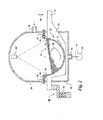
- FIG. 2 shows a version of the coating apparatus according to the invention in which an array of air passages is formed in the trough, and upper and lower air plenums are formed by cooperation of the trough with enclosures respectively above and below the trough. These air plenums are provided in order to maintain a flow of air through the air passages and through the bed of pellets in the trough.
- the trough 62 is a vibrating trough, supported on a set of arms similar to arms 42-48 in FIG. 1 .
- One such arm, 64 is shown in FIG. 2 , and is supported at one end on a mounting structure 66, which includes an elastomeric bar 68.
- the opposite end 70 of the arm 64 is connected to a energy source (not shown) similar to energy source 54 in FIG. 1 .
- An array of air passages 72 is formed in the trough.
- the passages are smaller than the pellets in the pellet bed 74 in the trough, and situated so that most of the openings are below the top of the bed.
- the trough is provided with a pair of flanges 76 and 78, which extend longitudinally along its upper edges.
- Elastomeric sealing strips 80 and 82 are clamped between the respective flanges and clamping strips 84 and 86, and extend between flanges of upper and lower enclosures 88 and 90.
- An upper enclosure 88 has an air passage 92
- the lower enclosure 90 has an air passage 94.
- the pellet bed 74 is fluidized as a result of vibrations imparted to the trough through the arms including arm 64, which vibrates up and down about an axis at the location of elastomeric bar 68 in the directions indicated by the double-ended arrow 96.
- the motion of the trough substantially fluidizes the bed of pellets, and causes the pellets to circulate in a rotating path as indicated by arrow 98.
- air passes into the upper plenum through passage 92, downward through the pellet bed 74 and passages 72 into the lower plenum, and outward through passage 94 and blower 100.
- the upper and lower enclosures do not need to be sealed perfectly, and in the embodiment shown, for example, the arms on which the trough are mounted extend through slots in the lower enclosure 90.
- Pellets are fed into, and discharged from, the vibrating trough, through suitable airlocks (not shown), for example, through rotary plate feeders of the kind illustrated in United States Patent 6,416,261, dated July 9, 2002 , the disclosure of which is incorporated by reference.
- the flow of air through the bed of pellets provides for more uniform distribution and drying of the coating material, and reduces the loss of particles of the spray from the spray nozzles, e.g., nozzle 102, to the atmosphere.
- the flow of air through the pellet bed is maintained by drawing air outward from the lower plenum by a blower 100, as an alternative, air can be forced into the upper plenum through passage 92. In some instances it may be desirable to maintain an upward flow of air, i.e., a flow of air into the pellet bed in the trough through the holes 72.
- blower 100 can be arranged to blow air into the lower plenum through passage 94, or a blower can be used to draw air outward from the upper plenum through passage 92.
- the temperature and humidity of the air flowing through the bed of pellets can be controlled in order to maintain proper coating conditions.
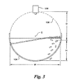
- a typical trough 104 has an arcuate cross-section.
- the arc is centered on a center line C (shown endwise as a point in FIG. 4 ).
- Pellets are discharged from the pellet bed in the trough over the upper edge of a weir.
- the weir maintains the top of the fluidized pellet bed substantially at a fixed position so that the center of the top of the pellet bed remains at a constant height H, measured from the bottom of the trough.
- H the height measured from the bottom of the trough.
- the top of the bed will ordinarily be at an angle in the range of about 10 to 20 degrees from horizontal.
- the pattern of circulation of the pellets in the trough, and other factors such as air flow and the nature of the pellets, the top of the bed can be disposed at an angle outside the 10 to 20 degree range.
- the bed if at rest, would have a width W, measured in a direction transverse to the direction of elongation of the trough. Because the pellet bed is coated in a vibrating trough, instead of in a conventional rotating drum, it is possible for the spray nozzle 106, or parts of the spray nozzle, to be located above the cylinder 108 that would be formed if the arcuate inner wall of the trough were continued to form a complete cylinder.
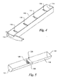
- the trough 110 shown in FIG. 4 can be used in the coating apparatus of FIG. 1 , or in the coating apparatus of FIG. 2 .
- This trough 110 has a discharge weir 112 at one end, a barrier 114 at the opposite end, which is higher than the discharge weir, at the opposite end, and a series of intermediate weirs 116.
- the height of each of the intermediate weirs is preferably less than the height of the discharge weir 112, and is also preferably such that each of the intermediate weirs is entirely underneath the surface of the pellet bed when the trough is vibrating.
- the intermediate weirs block longitudinal movement of lower parts of the pellet bed and improve the uniformity of the residence time of each pellet in the trough. It is possible to use a single intermediate weir or a plurality of intermediate weirs as shown.
- One or more intermediate weirs can also be made hollow and provide with an array of holes for passage of air into or out of a trough.
- a trough 118 having a discharge weir 120 at one end and a barrier 122 at the opposite end, is formed with an intermediate weir 124.
- the intermediate weir is hollow, forming a tunnel 126 extending underneath the trough in a direction transverse to its longitudinal direction.
- the wall 128 of the weir which faces toward the discharge end of the trough, is preferably, but not necessarily, vertical or nearly vertical, and has an array of air passages.
- the opposite face of the intermediate weir (not shown in FIG. 5 ) can have a similar array of air passages.
- the trough of FIG. 5 can be used in a coating apparatus having an upper air plenum, a lower air plenum, or both as in FIG. 2 .
- the air passages are in walls of the weir that are either vertical or nearly vertical, the vertical component of the velocity of the air flow through the pellet bed is small and has only a negligible effect on the circulation of pellets resulting from vibration of the trough.
- the air flow can be effective in maintaining uniform coating conditions.
- the air flow can be directed either inward through the air passages to the pellet bed, or outward from the pellet bed through the air passages.
- the hollow weir also has the advantage of achieving a more uniform residence time, and, of course, plural hollow weirs can be provided in a trough.
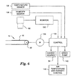
- the spectrometer 60 ( FIG. 1 ) is sensitive to the color of the coating on the pellets in the pellet bed passing underneath it. The color is a function of coating thickness.
- a monitor 130 e.g., a spectrometer, responsive to the sensor 60, generates a signal corresponding to coating thickness, and operates a motor control 132, which, in turn, controls the speed of a servomotor 134 which operates the pellet feeder 10. If the coating becomes too thin, the rate at which pellets are fed to the trough can be reduced, and their residence time in the trough will be increased. Thus, a uniform coating thickness can be maintained.
- the signal from the monitor 130 can be used to control the vibration rate or intensity, or spray velocity, in addition to, or as an alternative to, controlling the pellet feed rate.
- the temperature and/or humidity of the exhaust air can also be monitored and used to control operating parameters or combinations thereof, including air temperature, humidity, spray velocity, as well as pellet feed rate, and trough vibration rate or intensity.
- the control 132 can also receive inputs from an air temperature sensor 136 and a humidity sensor 138, and delivers control signals to an air temperature and humidity control 140 and a spray pump 142.
- the depth of the tablet bed can be made more nearly uniform along the length of the trough thereby reducing the maximum depth of the bed.
- the depth of the tablet bed 144 gradually decreases from the inlet end 146 of the trough toward the outlet end 148.
- the shape of the tablet bed in the trough is affected by the tablet feed rate, by the vibration of the trough, by drag due to friction between the tables and the inner surface of the trough, and by gravity.
- the surface of the tablet bed slopes downward from the side at which the magnitude of trough vibration is maximum toward the opposite side of the trough, and also from the inlet end toward the outlet end.
- the trough can be open as shown in FIG. 1 , or provided with an upper air plenum as shown in FIG. 2 , as an alternative, the trough can be the lower part of a closed channel that is vibrated.
- the closed channel can even have a circular cross-section if sufficiently large that the spray nozzles are not too close to the pellet bed.
- the trough is a lower part of a closed channel, the channel will have a non-circular shape, with a vertically elongated transverse cross-section.
- the continuous coating apparatus of claim 1 comprises a linear trough
- the trough can have a toroidal configuration similar to that of the vibration mill described in United States patent 3,100,088, granted on August 6, 1963 to H. L. Podmore et al. and incorporated herein by reference.
- the impulses imparted to the toroidal container by an eccentric weight on a centrally located motor will cause circulating movement of pellets in the container as they travel along the length of the trough.
- Another example is a configuration in which the coating apparatus is composed of a series of vibrating troughs, located one above another, and arranged so that pellets are fed from an upper trough to a next trough, and the pellet beds travel in alternating directions in the respective troughs.
- Still other trough configurations such as an arcuate configuration, or a helical configuration as in United States patent 5,067,431, granted on November 26, 1991 to Charles E. Heitmiller , can also be utilized.
Landscapes
- Chemical & Material Sciences (AREA)
- Health & Medical Sciences (AREA)
- Organic Chemistry (AREA)
- Chemical Kinetics & Catalysis (AREA)
- Medicinal Chemistry (AREA)
- Veterinary Medicine (AREA)
- Epidemiology (AREA)
- Life Sciences & Earth Sciences (AREA)
- Animal Behavior & Ethology (AREA)
- General Health & Medical Sciences (AREA)
- Public Health (AREA)
- Pharmacology & Pharmacy (AREA)
- Engineering & Computer Science (AREA)
- Bioinformatics & Cheminformatics (AREA)
- Glanulating (AREA)
- Medical Preparation Storing Or Oral Administration Devices (AREA)
- Medicinal Preparation (AREA)
- Processing And Handling Of Plastics And Other Materials For Molding In General (AREA)
Priority Applications (1)
| Application Number | Priority Date | Filing Date | Title |
|---|---|---|---|
| PL08730071T PL2117724T3 (pl) | 2007-02-21 | 2008-02-18 | Powlekanie peletek w sposób ciągły |
Applications Claiming Priority (3)
| Application Number | Priority Date | Filing Date | Title |
|---|---|---|---|
| US89089207P | 2007-02-21 | 2007-02-21 | |
| US2143608P | 2008-01-16 | 2008-01-16 | |
| PCT/US2008/054192 WO2008103622A1 (en) | 2007-02-21 | 2008-02-18 | Continuous coating of pellets |
Publications (3)
| Publication Number | Publication Date |
|---|---|
| EP2117724A1 EP2117724A1 (en) | 2009-11-18 |
| EP2117724A4 EP2117724A4 (en) | 2012-06-27 |
| EP2117724B1 true EP2117724B1 (en) | 2015-04-15 |
Family
ID=39710445
Family Applications (1)
| Application Number | Title | Priority Date | Filing Date |
|---|---|---|---|
| EP08730071.1A Active EP2117724B1 (en) | 2007-02-21 | 2008-02-18 | Continuous coating of pellets |
Country Status (10)
| Country | Link |
|---|---|
| US (2) | US8887659B2 (pl) |
| EP (1) | EP2117724B1 (pl) |
| KR (1) | KR101486603B1 (pl) |
| CN (1) | CN101687216B (pl) |
| AU (1) | AU2008218792B2 (pl) |
| CA (1) | CA2678931C (pl) |
| ES (1) | ES2541498T3 (pl) |
| MX (1) | MX2009009036A (pl) |
| PL (1) | PL2117724T3 (pl) |
| WO (1) | WO2008103622A1 (pl) |
Families Citing this family (36)
| Publication number | Priority date | Publication date | Assignee | Title |
|---|---|---|---|---|
| WO2010132634A1 (en) * | 2009-05-15 | 2010-11-18 | Glaxosmithkline Llc | Using thermal imaging for control of a manufacturing process |
| US10104903B2 (en) | 2009-07-31 | 2018-10-23 | Mars, Incorporated | Animal food and its appearance |
| US20110027417A1 (en) | 2009-07-31 | 2011-02-03 | Patrick Joseph Corrigan | Process for Dusting Animal Food |
| US8905624B1 (en) | 2009-08-20 | 2014-12-09 | Harold W. Howe | Control of vibratory/oscillatory mixers |
| JP4877372B2 (ja) * | 2009-08-28 | 2012-02-15 | カシオ計算機株式会社 | 塗布装置及び塗布方法 |
| FR2957830B1 (fr) * | 2010-03-26 | 2012-04-20 | Snecma | Dispositif de maintien d'une piece pour un depot total d'un revetement protecteur. |
| US9861027B2 (en) * | 2010-12-08 | 2018-01-09 | Bayer Cropscience, Lp | Seed treatment systems and methods |
| ES2532378T3 (es) * | 2011-01-20 | 2015-03-26 | The Procter & Gamble Company | Proceso para fabricar alimento para mascotas |
| US10130924B2 (en) | 2012-05-31 | 2018-11-20 | Resodyn Corporation | Mechanical system that fluidizes, mixes, coats, dries, combines, chemically reacts, and segregates materials |
| US10967355B2 (en) | 2012-05-31 | 2021-04-06 | Resodyn Corporation | Continuous acoustic chemical microreactor |
| US9808778B2 (en) | 2012-05-31 | 2017-11-07 | Resodyn Corporation | Mechanical system that continuously processes a combination of materials |
| US9747625B2 (en) | 2014-04-16 | 2017-08-29 | Dean Travis | Device for adding enhancers to pet food and method of using same |
| CN104689947B (zh) * | 2013-12-06 | 2018-02-13 | 大连隆星新材料有限公司 | 一种用于石蜡球成型以及表面全覆盖涂层系统 |
| CN104741299A (zh) * | 2013-12-29 | 2015-07-01 | 上海逸舟塑胶五金有限公司 | 软管的银粉涂装装置及其涂装方法 |
| US9481011B2 (en) * | 2014-11-11 | 2016-11-01 | Mark N. Halper | Method and apparatus for adding dry colorant to landscape mulch fiber |
| US11388914B2 (en) | 2015-04-28 | 2022-07-19 | Mars, Incorporated | Process of preparing a wet pet food, wet pet food produced by the process and uses thereof |
| CN105149164A (zh) * | 2015-09-25 | 2015-12-16 | 天津天美环保科技有限公司 | 一种多功能涂胶设备 |
| CN105538924A (zh) * | 2016-02-15 | 2016-05-04 | 陈吉美 | 一种新型药品广告喷涂加工生产线 |
| CN107008617B (zh) * | 2017-03-27 | 2019-02-15 | 嘉兴顾翔制冷设备有限公司 | 一种顶盖装配机 |
| IT201700047403A1 (it) | 2017-05-03 | 2018-11-03 | Ima Spa | Apparato e Metodo per Rivestire Materiale Sfuso |
| US10835880B2 (en) | 2017-09-05 | 2020-11-17 | Resodyn Corporation | Continuous acoustic mixer |
| CN107467697B (zh) * | 2017-09-28 | 2023-08-01 | 新希望六和饲料股份有限公司 | 一种饲料酶后喷涂装置 |
| CN107625184B (zh) * | 2017-09-28 | 2023-08-01 | 新希望六和饲料股份有限公司 | 一种添加饲料酶的生产设备 |
| CN107744167B (zh) * | 2017-11-17 | 2023-02-03 | 哈尔滨纳诺机械设备有限公司 | 连续式包衣机及采用该连续式包衣机的连续式包衣方法 |
| NL2020164B1 (en) * | 2017-12-22 | 2019-07-01 | Marel Further Proc Bv | Coating of food products with a particulate coating material |
| CN110856690B (zh) * | 2018-08-22 | 2024-07-02 | 深圳善康医药科技股份有限公司 | 一种植入剂包膜及干燥装置 |
| JP7302996B2 (ja) * | 2019-03-20 | 2023-07-04 | 株式会社前川製作所 | 混和装置 |
| CN110742806B (zh) * | 2019-10-22 | 2025-04-29 | 浙江迦南科技股份有限公司 | 包衣机片床喷雾装置和控制方法 |
| CN110711667B (zh) * | 2019-11-08 | 2020-12-01 | 山东高强紧固件有限公司 | 一种履带螺栓螺帽涂装设备 |
| CN110833965A (zh) * | 2019-12-09 | 2020-02-25 | 福建盈浩文化创意股份有限公司 | 闪粉圣诞球喷涂设备及其工作方法 |
| CN111228119A (zh) * | 2020-01-30 | 2020-06-05 | 马尧顺 | 一种化工制药用包衣机 |
| CN112808477B (zh) * | 2020-12-30 | 2022-05-10 | 中冶建筑研究总院有限公司 | 一种用于钢渣表面涂覆处理的装置 |
| CN117380500A (zh) * | 2023-04-18 | 2024-01-12 | 唐山凯伦新材料科技有限公司 | 一种防水卷材的生产工艺 |
| CN116493184B (zh) * | 2023-06-26 | 2023-09-22 | 淄博齐茂催化剂有限公司 | 一种汽油加氢精制催化剂制备装置 |
| CN116919825B (zh) * | 2023-09-18 | 2023-12-05 | 北京爱力佳医药科技有限公司 | 一种药品加工用包衣装置 |
| CN119522687B (zh) * | 2024-12-13 | 2025-07-11 | 无棣惠农种子科技有限公司 | 一种玉米种子包衣丸化设备 |
Family Cites Families (24)
| Publication number | Priority date | Publication date | Assignee | Title |
|---|---|---|---|---|
| US3733056A (en) * | 1971-01-11 | 1973-05-15 | L Fong | Fluidized bed and method of treating granular material |
| US3765532A (en) * | 1971-07-12 | 1973-10-16 | Rex Chainbelt Inc | Wood chip washer |
| US4066024A (en) * | 1975-12-24 | 1978-01-03 | Oconnor Chadwell | Rotating fluidized bed combustor |
| US4050406A (en) * | 1976-02-05 | 1977-09-27 | Reni-Cirillo S.R.L. | Coating machine for confectionery, pharmaceuticals and similar products |
| US4256785A (en) | 1979-07-25 | 1981-03-17 | Eastman Kodak Company | Pellet coating process |
| US4576572A (en) * | 1984-03-29 | 1986-03-18 | Whirl-Air-Flow Corporation | Apparatus and method for cleaning contaminated soil |
| JPS6411632A (en) * | 1987-07-06 | 1989-01-17 | Tdk Corp | Fluidization granulator |
| US5067431A (en) | 1990-02-06 | 1991-11-26 | Carrier Vibrating Equipment, Inc. | Vibrating article coating and conveying apparatus |
| US5271012A (en) * | 1991-02-11 | 1993-12-14 | International Business Machines Corporation | Method and means for encoding and rebuilding data contents of up to two unavailable DASDs in an array of DASDs |
| US5615606A (en) * | 1991-12-20 | 1997-04-01 | Vos Industries Pty. Ltd. | Conveyor |
| US5443637A (en) * | 1993-09-17 | 1995-08-22 | Coating Machinery Systems, Inc. | Means for continuously coating particulate material |
| US5470387A (en) * | 1994-03-07 | 1995-11-28 | Niro A/S | Continuous multicell process and apparatus for particle coating including particle recirculation |
| US5567238A (en) | 1994-12-06 | 1996-10-22 | Coating Machinery Systems, Inc. | Oscillating bed seed coating machine for particulate material |
| US7008668B2 (en) * | 1995-05-09 | 2006-03-07 | Phoqus Pharmaceuticals Limited | Powder coating composition for electrostatic coating of pharmaceutical substrates |
| JP3928010B2 (ja) * | 1997-07-31 | 2007-06-13 | アグリテクノ矢崎株式会社 | 種子のゲル被覆加工装置 |
| DE19838540C2 (de) | 1998-08-25 | 2001-07-26 | Herbert Huettlin | Verfahren zum Behandeln eines partikelförmigen Guts mit einem Überzugsmedium sowie Vorrichtung zur Durchführung eines derartigen Verfahrens |
| US6730349B2 (en) * | 1999-04-19 | 2004-05-04 | Scimed Life Systems, Inc. | Mechanical and acoustical suspension coating of medical implants |
| US6579365B1 (en) | 1999-11-22 | 2003-06-17 | Glatt Air Techniques, Inc. | Apparatus for coating tablets |
| JP3681978B2 (ja) * | 2000-12-19 | 2005-08-10 | 株式会社巴川製紙所 | 光反射板および反射型液晶表示装置 |
| DE10130334A1 (de) * | 2001-06-26 | 2003-01-02 | Glatt Ingtech Gmbh | Verfahren zum Coating von körnigen und pulverförmigen Materialien |
| US20030044524A1 (en) * | 2001-09-05 | 2003-03-06 | Hoffland Derrick B. | Vibratory electrostatic fluidized bed for powder paint coating |
| JP3705599B2 (ja) | 2002-12-26 | 2005-10-12 | 旭化成ケミカルズ株式会社 | 導電性マスターバッチ及び導電性樹脂組成物 |
| CA2455192A1 (en) * | 2004-01-14 | 2005-07-14 | David O'hara | Rotary drum for tablet coating with reverse-direction unloading |
| TWI547431B (zh) * | 2004-06-09 | 2016-09-01 | 史密斯克萊美占公司 | 生產藥物之裝置及方法 |
-
2008
- 2008-02-18 AU AU2008218792A patent/AU2008218792B2/en not_active Ceased
- 2008-02-18 PL PL08730071T patent/PL2117724T3/pl unknown
- 2008-02-18 WO PCT/US2008/054192 patent/WO2008103622A1/en not_active Ceased
- 2008-02-18 US US12/527,885 patent/US8887659B2/en active Active
- 2008-02-18 EP EP08730071.1A patent/EP2117724B1/en active Active
- 2008-02-18 KR KR1020097019533A patent/KR101486603B1/ko not_active Expired - Fee Related
- 2008-02-18 ES ES08730071.1T patent/ES2541498T3/es active Active
- 2008-02-18 CN CN2008800123860A patent/CN101687216B/zh active Active
- 2008-02-18 CA CA2678931A patent/CA2678931C/en active Active
- 2008-02-18 MX MX2009009036A patent/MX2009009036A/es active IP Right Grant
-
2014
- 2014-10-15 US US14/514,464 patent/US9597294B2/en active Active
Also Published As
| Publication number | Publication date |
|---|---|
| KR20090115212A (ko) | 2009-11-04 |
| WO2008103622A1 (en) | 2008-08-28 |
| PL2117724T3 (pl) | 2015-09-30 |
| CA2678931A1 (en) | 2008-08-28 |
| CN101687216B (zh) | 2013-03-06 |
| CA2678931C (en) | 2014-09-16 |
| CN101687216A (zh) | 2010-03-31 |
| EP2117724A1 (en) | 2009-11-18 |
| US20100080897A1 (en) | 2010-04-01 |
| US8887659B2 (en) | 2014-11-18 |
| MX2009009036A (es) | 2009-08-31 |
| ES2541498T3 (es) | 2015-07-21 |
| EP2117724A4 (en) | 2012-06-27 |
| AU2008218792B2 (en) | 2012-04-05 |
| AU2008218792A1 (en) | 2008-08-28 |
| US20150030756A1 (en) | 2015-01-29 |
| KR101486603B1 (ko) | 2015-01-26 |
| US9597294B2 (en) | 2017-03-21 |
Similar Documents
| Publication | Publication Date | Title |
|---|---|---|
| EP2117724B1 (en) | Continuous coating of pellets | |
| US8978576B2 (en) | Spiral gas-solids contact apparatus | |
| US4907720A (en) | Method and apparatus for uniformly dispensing a seasoning material | |
| JP3954107B2 (ja) | 粉末充填システム、装置及び方法 | |
| JPH0234652B2 (pl) | ||
| US6695989B1 (en) | Apparatus and method for manufacturing granules | |
| US5846324A (en) | Seasoning spreader | |
| JPS60232273A (ja) | 物品の回分式コーテイング方法及び装置 | |
| JP3756191B2 (ja) | 粒状材料を処理するための装置及び方法 | |
| IE903819A1 (en) | A fluidized bed apparatus for making and/or processing¹pourable material | |
| JPH05168906A (ja) | 流動床コンディショニング装置 | |
| CA2773806C (en) | System and method for coating bulk articles | |
| HU196717B (en) | Apparatus and method for fluidization contacting materials | |
| US4542043A (en) | Method and apparatus for continuously coating discrete particles in turning fluidized bed | |
| US6045855A (en) | Electrostatic coating of small falling objects | |
| JP2003225599A (ja) | コーティング装置 | |
| US6966453B2 (en) | Apparatus and method for regulating the delivery of bulk tablets to a tablet transport system | |
| WO2006061576A1 (en) | Food item coating apparatus and method |
Legal Events
| Date | Code | Title | Description |
|---|---|---|---|
| PUAI | Public reference made under article 153(3) epc to a published international application that has entered the european phase |
Free format text: ORIGINAL CODE: 0009012 |
|
| 17P | Request for examination filed |
Effective date: 20090901 |
|
| AK | Designated contracting states |
Kind code of ref document: A1 Designated state(s): AT BE BG CH CY CZ DE DK EE ES FI FR GB GR HR HU IE IS IT LI LT LU LV MC MT NL NO PL PT RO SE SI SK TR |
|
| RAP1 | Party data changed (applicant data changed or rights of an application transferred) |
Owner name: GLAXOSMITHKLINE LLC |
|
| DAX | Request for extension of the european patent (deleted) | ||
| A4 | Supplementary search report drawn up and despatched |
Effective date: 20120525 |
|
| RIC1 | Information provided on ipc code assigned before grant |
Ipc: B05D 3/00 20060101AFI20120521BHEP Ipc: B01J 8/36 20060101ALI20120521BHEP Ipc: B05C 13/00 20060101ALI20120521BHEP Ipc: B01J 8/40 20060101ALI20120521BHEP Ipc: B01J 2/18 20060101ALI20120521BHEP |
|
| RAP1 | Party data changed (applicant data changed or rights of an application transferred) |
Owner name: GLAXOSMITHKLINE LLC |
|
| GRAP | Despatch of communication of intention to grant a patent |
Free format text: ORIGINAL CODE: EPIDOSNIGR1 |
|
| INTG | Intention to grant announced |
Effective date: 20141119 |
|
| GRAS | Grant fee paid |
Free format text: ORIGINAL CODE: EPIDOSNIGR3 |
|
| GRAA | (expected) grant |
Free format text: ORIGINAL CODE: 0009210 |
|
| AK | Designated contracting states |
Kind code of ref document: B1 Designated state(s): AT BE BG CH CY CZ DE DK EE ES FI FR GB GR HR HU IE IS IT LI LT LU LV MC MT NL NO PL PT RO SE SI SK TR |
|
| REG | Reference to a national code |
Ref country code: GB Ref legal event code: FG4D Ref country code: CH Ref legal event code: EP |
|
| REG | Reference to a national code |
Ref country code: IE Ref legal event code: FG4D |
|
| REG | Reference to a national code |
Ref country code: AT Ref legal event code: REF Ref document number: 721654 Country of ref document: AT Kind code of ref document: T Effective date: 20150515 |
|
| REG | Reference to a national code |
Ref country code: DE Ref legal event code: R096 Ref document number: 602008037683 Country of ref document: DE Effective date: 20150521 |
|
| REG | Reference to a national code |
Ref country code: ES Ref legal event code: FG2A Ref document number: 2541498 Country of ref document: ES Kind code of ref document: T3 Effective date: 20150721 |
|
| REG | Reference to a national code |
Ref country code: NL Ref legal event code: VDEP Effective date: 20150415 |
|
| REG | Reference to a national code |
Ref country code: AT Ref legal event code: MK05 Ref document number: 721654 Country of ref document: AT Kind code of ref document: T Effective date: 20150415 |
|
| REG | Reference to a national code |
Ref country code: LT Ref legal event code: MG4D |
|
| PG25 | Lapsed in a contracting state [announced via postgrant information from national office to epo] |
Ref country code: NL Free format text: LAPSE BECAUSE OF FAILURE TO SUBMIT A TRANSLATION OF THE DESCRIPTION OR TO PAY THE FEE WITHIN THE PRESCRIBED TIME-LIMIT Effective date: 20150415 |
|
| REG | Reference to a national code |
Ref country code: PL Ref legal event code: T3 |
|
| PG25 | Lapsed in a contracting state [announced via postgrant information from national office to epo] |
Ref country code: LT Free format text: LAPSE BECAUSE OF FAILURE TO SUBMIT A TRANSLATION OF THE DESCRIPTION OR TO PAY THE FEE WITHIN THE PRESCRIBED TIME-LIMIT Effective date: 20150415 Ref country code: FI Free format text: LAPSE BECAUSE OF FAILURE TO SUBMIT A TRANSLATION OF THE DESCRIPTION OR TO PAY THE FEE WITHIN THE PRESCRIBED TIME-LIMIT Effective date: 20150415 Ref country code: HR Free format text: LAPSE BECAUSE OF FAILURE TO SUBMIT A TRANSLATION OF THE DESCRIPTION OR TO PAY THE FEE WITHIN THE PRESCRIBED TIME-LIMIT Effective date: 20150415 Ref country code: PT Free format text: LAPSE BECAUSE OF FAILURE TO SUBMIT A TRANSLATION OF THE DESCRIPTION OR TO PAY THE FEE WITHIN THE PRESCRIBED TIME-LIMIT Effective date: 20150817 Ref country code: NO Free format text: LAPSE BECAUSE OF FAILURE TO SUBMIT A TRANSLATION OF THE DESCRIPTION OR TO PAY THE FEE WITHIN THE PRESCRIBED TIME-LIMIT Effective date: 20150715 |
|
| PG25 | Lapsed in a contracting state [announced via postgrant information from national office to epo] |
Ref country code: LV Free format text: LAPSE BECAUSE OF FAILURE TO SUBMIT A TRANSLATION OF THE DESCRIPTION OR TO PAY THE FEE WITHIN THE PRESCRIBED TIME-LIMIT Effective date: 20150415 Ref country code: GR Free format text: LAPSE BECAUSE OF FAILURE TO SUBMIT A TRANSLATION OF THE DESCRIPTION OR TO PAY THE FEE WITHIN THE PRESCRIBED TIME-LIMIT Effective date: 20150716 Ref country code: AT Free format text: LAPSE BECAUSE OF FAILURE TO SUBMIT A TRANSLATION OF THE DESCRIPTION OR TO PAY THE FEE WITHIN THE PRESCRIBED TIME-LIMIT Effective date: 20150415 Ref country code: IS Free format text: LAPSE BECAUSE OF FAILURE TO SUBMIT A TRANSLATION OF THE DESCRIPTION OR TO PAY THE FEE WITHIN THE PRESCRIBED TIME-LIMIT Effective date: 20150815 |
|
| REG | Reference to a national code |
Ref country code: DE Ref legal event code: R097 Ref document number: 602008037683 Country of ref document: DE |
|
| REG | Reference to a national code |
Ref country code: FR Ref legal event code: PLFP Year of fee payment: 9 |
|
| PG25 | Lapsed in a contracting state [announced via postgrant information from national office to epo] |
Ref country code: EE Free format text: LAPSE BECAUSE OF FAILURE TO SUBMIT A TRANSLATION OF THE DESCRIPTION OR TO PAY THE FEE WITHIN THE PRESCRIBED TIME-LIMIT Effective date: 20150415 Ref country code: DK Free format text: LAPSE BECAUSE OF FAILURE TO SUBMIT A TRANSLATION OF THE DESCRIPTION OR TO PAY THE FEE WITHIN THE PRESCRIBED TIME-LIMIT Effective date: 20150415 |
|
| PLBE | No opposition filed within time limit |
Free format text: ORIGINAL CODE: 0009261 |
|
| STAA | Information on the status of an ep patent application or granted ep patent |
Free format text: STATUS: NO OPPOSITION FILED WITHIN TIME LIMIT |
|
| PG25 | Lapsed in a contracting state [announced via postgrant information from national office to epo] |
Ref country code: SK Free format text: LAPSE BECAUSE OF FAILURE TO SUBMIT A TRANSLATION OF THE DESCRIPTION OR TO PAY THE FEE WITHIN THE PRESCRIBED TIME-LIMIT Effective date: 20150415 Ref country code: RO Free format text: LAPSE BECAUSE OF NON-PAYMENT OF DUE FEES Effective date: 20150415 Ref country code: CZ Free format text: LAPSE BECAUSE OF FAILURE TO SUBMIT A TRANSLATION OF THE DESCRIPTION OR TO PAY THE FEE WITHIN THE PRESCRIBED TIME-LIMIT Effective date: 20150415 |
|
| 26N | No opposition filed |
Effective date: 20160118 |
|
| PG25 | Lapsed in a contracting state [announced via postgrant information from national office to epo] |
Ref country code: SI Free format text: LAPSE BECAUSE OF FAILURE TO SUBMIT A TRANSLATION OF THE DESCRIPTION OR TO PAY THE FEE WITHIN THE PRESCRIBED TIME-LIMIT Effective date: 20150415 Ref country code: BE Free format text: LAPSE BECAUSE OF NON-PAYMENT OF DUE FEES Effective date: 20160229 |
|
| PG25 | Lapsed in a contracting state [announced via postgrant information from national office to epo] |
Ref country code: BE Free format text: LAPSE BECAUSE OF FAILURE TO SUBMIT A TRANSLATION OF THE DESCRIPTION OR TO PAY THE FEE WITHIN THE PRESCRIBED TIME-LIMIT Effective date: 20150415 |
|
| PG25 | Lapsed in a contracting state [announced via postgrant information from national office to epo] |
Ref country code: LU Free format text: LAPSE BECAUSE OF FAILURE TO SUBMIT A TRANSLATION OF THE DESCRIPTION OR TO PAY THE FEE WITHIN THE PRESCRIBED TIME-LIMIT Effective date: 20160218 Ref country code: MC Free format text: LAPSE BECAUSE OF FAILURE TO SUBMIT A TRANSLATION OF THE DESCRIPTION OR TO PAY THE FEE WITHIN THE PRESCRIBED TIME-LIMIT Effective date: 20150415 |
|
| REG | Reference to a national code |
Ref country code: CH Ref legal event code: PL |
|
| PG25 | Lapsed in a contracting state [announced via postgrant information from national office to epo] |
Ref country code: CH Free format text: LAPSE BECAUSE OF NON-PAYMENT OF DUE FEES Effective date: 20160229 Ref country code: LI Free format text: LAPSE BECAUSE OF NON-PAYMENT OF DUE FEES Effective date: 20160229 |
|
| REG | Reference to a national code |
Ref country code: IE Ref legal event code: MM4A |
|
| REG | Reference to a national code |
Ref country code: FR Ref legal event code: PLFP Year of fee payment: 10 |
|
| PG25 | Lapsed in a contracting state [announced via postgrant information from national office to epo] |
Ref country code: IE Free format text: LAPSE BECAUSE OF NON-PAYMENT OF DUE FEES Effective date: 20160218 |
|
| PG25 | Lapsed in a contracting state [announced via postgrant information from national office to epo] |
Ref country code: SE Free format text: LAPSE BECAUSE OF FAILURE TO SUBMIT A TRANSLATION OF THE DESCRIPTION OR TO PAY THE FEE WITHIN THE PRESCRIBED TIME-LIMIT Effective date: 20150415 |
|
| PG25 | Lapsed in a contracting state [announced via postgrant information from national office to epo] |
Ref country code: MT Free format text: LAPSE BECAUSE OF FAILURE TO SUBMIT A TRANSLATION OF THE DESCRIPTION OR TO PAY THE FEE WITHIN THE PRESCRIBED TIME-LIMIT Effective date: 20150415 |
|
| REG | Reference to a national code |
Ref country code: FR Ref legal event code: PLFP Year of fee payment: 11 |
|
| PG25 | Lapsed in a contracting state [announced via postgrant information from national office to epo] |
Ref country code: HU Free format text: LAPSE BECAUSE OF FAILURE TO SUBMIT A TRANSLATION OF THE DESCRIPTION OR TO PAY THE FEE WITHIN THE PRESCRIBED TIME-LIMIT; INVALID AB INITIO Effective date: 20080218 Ref country code: CY Free format text: LAPSE BECAUSE OF FAILURE TO SUBMIT A TRANSLATION OF THE DESCRIPTION OR TO PAY THE FEE WITHIN THE PRESCRIBED TIME-LIMIT Effective date: 20150415 |
|
| REG | Reference to a national code |
Ref country code: FR Ref legal event code: CA Effective date: 20180515 |
|
| PG25 | Lapsed in a contracting state [announced via postgrant information from national office to epo] |
Ref country code: TR Free format text: LAPSE BECAUSE OF FAILURE TO SUBMIT A TRANSLATION OF THE DESCRIPTION OR TO PAY THE FEE WITHIN THE PRESCRIBED TIME-LIMIT Effective date: 20150415 Ref country code: MT Free format text: LAPSE BECAUSE OF FAILURE TO SUBMIT A TRANSLATION OF THE DESCRIPTION OR TO PAY THE FEE WITHIN THE PRESCRIBED TIME-LIMIT Effective date: 20160229 |
|
| PG25 | Lapsed in a contracting state [announced via postgrant information from national office to epo] |
Ref country code: BG Free format text: LAPSE BECAUSE OF FAILURE TO SUBMIT A TRANSLATION OF THE DESCRIPTION OR TO PAY THE FEE WITHIN THE PRESCRIBED TIME-LIMIT Effective date: 20150415 |
|
| PGFP | Annual fee paid to national office [announced via postgrant information from national office to epo] |
Ref country code: DE Payment date: 20250122 Year of fee payment: 18 |
|
| PGFP | Annual fee paid to national office [announced via postgrant information from national office to epo] |
Ref country code: ES Payment date: 20250303 Year of fee payment: 18 |
|
| PGFP | Annual fee paid to national office [announced via postgrant information from national office to epo] |
Ref country code: PL Payment date: 20250122 Year of fee payment: 18 Ref country code: FR Payment date: 20250122 Year of fee payment: 18 |
|
| PGFP | Annual fee paid to national office [announced via postgrant information from national office to epo] |
Ref country code: IT Payment date: 20250121 Year of fee payment: 18 Ref country code: GB Payment date: 20250123 Year of fee payment: 18 |