EP2117475B1 - Système d'administration de stent entérique de type à échange rapide - Google Patents
Système d'administration de stent entérique de type à échange rapide Download PDFInfo
- Publication number
- EP2117475B1 EP2117475B1 EP08872019.8A EP08872019A EP2117475B1 EP 2117475 B1 EP2117475 B1 EP 2117475B1 EP 08872019 A EP08872019 A EP 08872019A EP 2117475 B1 EP2117475 B1 EP 2117475B1
- Authority
- EP
- European Patent Office
- Prior art keywords
- guidewire
- catheter
- mandrel
- proximal
- distal
- Prior art date
- Legal status (The legal status is an assumption and is not a legal conclusion. Google has not performed a legal analysis and makes no representation as to the accuracy of the status listed.)
- Active
Links
- 238000000034 method Methods 0.000 description 15
- 208000031481 Pathologic Constriction Diseases 0.000 description 10
- 239000000853 adhesive Substances 0.000 description 8
- 230000001070 adhesive effect Effects 0.000 description 8
- 229920002614 Polyether block amide Polymers 0.000 description 6
- 230000036961 partial effect Effects 0.000 description 6
- 238000004519 manufacturing process Methods 0.000 description 5
- 239000003550 marker Substances 0.000 description 5
- 239000007787 solid Substances 0.000 description 5
- 239000002131 composite material Substances 0.000 description 4
- 230000002496 gastric effect Effects 0.000 description 4
- 238000002347 injection Methods 0.000 description 4
- 239000007924 injection Substances 0.000 description 4
- 239000000463 material Substances 0.000 description 4
- 239000004810 polytetrafluoroethylene Substances 0.000 description 4
- 229920001343 polytetrafluoroethylene Polymers 0.000 description 4
- 238000006073 displacement reaction Methods 0.000 description 3
- 229910001220 stainless steel Inorganic materials 0.000 description 3
- 239000010935 stainless steel Substances 0.000 description 3
- 230000002792 vascular Effects 0.000 description 3
- 238000003466 welding Methods 0.000 description 3
- 210000003445 biliary tract Anatomy 0.000 description 2
- 239000008280 blood Substances 0.000 description 2
- 210000004369 blood Anatomy 0.000 description 2
- 238000007459 endoscopic retrograde cholangiopancreatography Methods 0.000 description 2
- 239000012530 fluid Substances 0.000 description 2
- 238000002844 melting Methods 0.000 description 2
- 230000008018 melting Effects 0.000 description 2
- 230000008569 process Effects 0.000 description 2
- 230000000452 restraining effect Effects 0.000 description 2
- VGGSQFUCUMXWEO-UHFFFAOYSA-N Ethene Chemical compound C=C VGGSQFUCUMXWEO-UHFFFAOYSA-N 0.000 description 1
- 206010028980 Neoplasm Diseases 0.000 description 1
- 239000004677 Nylon Substances 0.000 description 1
- 239000004696 Poly ether ether ketone Substances 0.000 description 1
- 239000004743 Polypropylene Substances 0.000 description 1
- 230000002159 abnormal effect Effects 0.000 description 1
- 210000003484 anatomy Anatomy 0.000 description 1
- 238000002399 angioplasty Methods 0.000 description 1
- JUPQTSLXMOCDHR-UHFFFAOYSA-N benzene-1,4-diol;bis(4-fluorophenyl)methanone Chemical compound OC1=CC=C(O)C=C1.C1=CC(F)=CC=C1C(=O)C1=CC=C(F)C=C1 JUPQTSLXMOCDHR-UHFFFAOYSA-N 0.000 description 1
- 210000001124 body fluid Anatomy 0.000 description 1
- 238000005219 brazing Methods 0.000 description 1
- 210000003459 common hepatic duct Anatomy 0.000 description 1
- 230000006835 compression Effects 0.000 description 1
- 238000007906 compression Methods 0.000 description 1
- 230000001010 compromised effect Effects 0.000 description 1
- 230000008878 coupling Effects 0.000 description 1
- 238000010168 coupling process Methods 0.000 description 1
- 238000005859 coupling reaction Methods 0.000 description 1
- 238000002788 crimping Methods 0.000 description 1
- 238000005520 cutting process Methods 0.000 description 1
- 230000001079 digestive effect Effects 0.000 description 1
- 230000009977 dual effect Effects 0.000 description 1
- 210000001198 duodenum Anatomy 0.000 description 1
- 238000002594 fluoroscopy Methods 0.000 description 1
- 238000010438 heat treatment Methods 0.000 description 1
- 230000002440 hepatic effect Effects 0.000 description 1
- 238000001802 infusion Methods 0.000 description 1
- 238000003780 insertion Methods 0.000 description 1
- 230000037431 insertion Effects 0.000 description 1
- 230000002452 interceptive effect Effects 0.000 description 1
- 210000000936 intestine Anatomy 0.000 description 1
- 230000003902 lesion Effects 0.000 description 1
- 230000000670 limiting effect Effects 0.000 description 1
- 229920001684 low density polyethylene Polymers 0.000 description 1
- 239000004702 low-density polyethylene Substances 0.000 description 1
- 239000002184 metal Substances 0.000 description 1
- 230000004048 modification Effects 0.000 description 1
- 238000012986 modification Methods 0.000 description 1
- 238000000465 moulding Methods 0.000 description 1
- 235000021590 normal diet Nutrition 0.000 description 1
- 229920001778 nylon Polymers 0.000 description 1
- 210000000277 pancreatic duct Anatomy 0.000 description 1
- 230000007170 pathology Effects 0.000 description 1
- 230000037361 pathway Effects 0.000 description 1
- 239000004033 plastic Substances 0.000 description 1
- 229920003023 plastic Polymers 0.000 description 1
- 229920002530 polyetherether ketone Polymers 0.000 description 1
- -1 polypropylene Polymers 0.000 description 1
- 229920001155 polypropylene Polymers 0.000 description 1
- 230000002829 reductive effect Effects 0.000 description 1
- 230000007704 transition Effects 0.000 description 1
- 238000012800 visualization Methods 0.000 description 1
- 230000003313 weakening effect Effects 0.000 description 1
- 230000003245 working effect Effects 0.000 description 1
Images


Classifications
-
- A—HUMAN NECESSITIES
- A61—MEDICAL OR VETERINARY SCIENCE; HYGIENE
- A61F—FILTERS IMPLANTABLE INTO BLOOD VESSELS; PROSTHESES; DEVICES PROVIDING PATENCY TO, OR PREVENTING COLLAPSING OF, TUBULAR STRUCTURES OF THE BODY, e.g. STENTS; ORTHOPAEDIC, NURSING OR CONTRACEPTIVE DEVICES; FOMENTATION; TREATMENT OR PROTECTION OF EYES OR EARS; BANDAGES, DRESSINGS OR ABSORBENT PADS; FIRST-AID KITS
- A61F2/00—Filters implantable into blood vessels; Prostheses, i.e. artificial substitutes or replacements for parts of the body; Appliances for connecting them with the body; Devices providing patency to, or preventing collapsing of, tubular structures of the body, e.g. stents
- A61F2/95—Instruments specially adapted for placement or removal of stents or stent-grafts
- A61F2/962—Instruments specially adapted for placement or removal of stents or stent-grafts having an outer sleeve
- A61F2/966—Instruments specially adapted for placement or removal of stents or stent-grafts having an outer sleeve with relative longitudinal movement between outer sleeve and prosthesis, e.g. using a push rod
-
- A—HUMAN NECESSITIES
- A61—MEDICAL OR VETERINARY SCIENCE; HYGIENE
- A61F—FILTERS IMPLANTABLE INTO BLOOD VESSELS; PROSTHESES; DEVICES PROVIDING PATENCY TO, OR PREVENTING COLLAPSING OF, TUBULAR STRUCTURES OF THE BODY, e.g. STENTS; ORTHOPAEDIC, NURSING OR CONTRACEPTIVE DEVICES; FOMENTATION; TREATMENT OR PROTECTION OF EYES OR EARS; BANDAGES, DRESSINGS OR ABSORBENT PADS; FIRST-AID KITS
- A61F2/00—Filters implantable into blood vessels; Prostheses, i.e. artificial substitutes or replacements for parts of the body; Appliances for connecting them with the body; Devices providing patency to, or preventing collapsing of, tubular structures of the body, e.g. stents
- A61F2/82—Devices providing patency to, or preventing collapsing of, tubular structures of the body, e.g. stents
- A61F2/844—Devices providing patency to, or preventing collapsing of, tubular structures of the body, e.g. stents folded prior to deployment
-
- A—HUMAN NECESSITIES
- A61—MEDICAL OR VETERINARY SCIENCE; HYGIENE
- A61F—FILTERS IMPLANTABLE INTO BLOOD VESSELS; PROSTHESES; DEVICES PROVIDING PATENCY TO, OR PREVENTING COLLAPSING OF, TUBULAR STRUCTURES OF THE BODY, e.g. STENTS; ORTHOPAEDIC, NURSING OR CONTRACEPTIVE DEVICES; FOMENTATION; TREATMENT OR PROTECTION OF EYES OR EARS; BANDAGES, DRESSINGS OR ABSORBENT PADS; FIRST-AID KITS
- A61F2/00—Filters implantable into blood vessels; Prostheses, i.e. artificial substitutes or replacements for parts of the body; Appliances for connecting them with the body; Devices providing patency to, or preventing collapsing of, tubular structures of the body, e.g. stents
- A61F2/82—Devices providing patency to, or preventing collapsing of, tubular structures of the body, e.g. stents
- A61F2/86—Stents in a form characterised by the wire-like elements; Stents in the form characterised by a net-like or mesh-like structure
- A61F2/90—Stents in a form characterised by the wire-like elements; Stents in the form characterised by a net-like or mesh-like structure characterised by a net-like or mesh-like structure
-
- A—HUMAN NECESSITIES
- A61—MEDICAL OR VETERINARY SCIENCE; HYGIENE
- A61F—FILTERS IMPLANTABLE INTO BLOOD VESSELS; PROSTHESES; DEVICES PROVIDING PATENCY TO, OR PREVENTING COLLAPSING OF, TUBULAR STRUCTURES OF THE BODY, e.g. STENTS; ORTHOPAEDIC, NURSING OR CONTRACEPTIVE DEVICES; FOMENTATION; TREATMENT OR PROTECTION OF EYES OR EARS; BANDAGES, DRESSINGS OR ABSORBENT PADS; FIRST-AID KITS
- A61F2/00—Filters implantable into blood vessels; Prostheses, i.e. artificial substitutes or replacements for parts of the body; Appliances for connecting them with the body; Devices providing patency to, or preventing collapsing of, tubular structures of the body, e.g. stents
- A61F2/95—Instruments specially adapted for placement or removal of stents or stent-grafts
-
- A—HUMAN NECESSITIES
- A61—MEDICAL OR VETERINARY SCIENCE; HYGIENE
- A61M—DEVICES FOR INTRODUCING MEDIA INTO, OR ONTO, THE BODY; DEVICES FOR TRANSDUCING BODY MEDIA OR FOR TAKING MEDIA FROM THE BODY; DEVICES FOR PRODUCING OR ENDING SLEEP OR STUPOR
- A61M25/00—Catheters; Hollow probes
-
- A—HUMAN NECESSITIES
- A61—MEDICAL OR VETERINARY SCIENCE; HYGIENE
- A61M—DEVICES FOR INTRODUCING MEDIA INTO, OR ONTO, THE BODY; DEVICES FOR TRANSDUCING BODY MEDIA OR FOR TAKING MEDIA FROM THE BODY; DEVICES FOR PRODUCING OR ENDING SLEEP OR STUPOR
- A61M25/00—Catheters; Hollow probes
- A61M25/0043—Catheters; Hollow probes characterised by structural features
- A61M2025/0063—Catheters; Hollow probes characterised by structural features having means, e.g. stylets, mandrils, rods or wires to reinforce or adjust temporarily the stiffness, column strength or pushability of catheters which are already inserted into the human body
-
- A—HUMAN NECESSITIES
- A61—MEDICAL OR VETERINARY SCIENCE; HYGIENE
- A61M—DEVICES FOR INTRODUCING MEDIA INTO, OR ONTO, THE BODY; DEVICES FOR TRANSDUCING BODY MEDIA OR FOR TAKING MEDIA FROM THE BODY; DEVICES FOR PRODUCING OR ENDING SLEEP OR STUPOR
- A61M25/00—Catheters; Hollow probes
- A61M25/01—Introducing, guiding, advancing, emplacing or holding catheters
- A61M2025/018—Catheters having a lateral opening for guiding elongated means lateral to the catheter
-
- A—HUMAN NECESSITIES
- A61—MEDICAL OR VETERINARY SCIENCE; HYGIENE
- A61M—DEVICES FOR INTRODUCING MEDIA INTO, OR ONTO, THE BODY; DEVICES FOR TRANSDUCING BODY MEDIA OR FOR TAKING MEDIA FROM THE BODY; DEVICES FOR PRODUCING OR ENDING SLEEP OR STUPOR
- A61M25/00—Catheters; Hollow probes
- A61M25/01—Introducing, guiding, advancing, emplacing or holding catheters
- A61M2025/0183—Rapid exchange or monorail catheters
-
- A—HUMAN NECESSITIES
- A61—MEDICAL OR VETERINARY SCIENCE; HYGIENE
- A61M—DEVICES FOR INTRODUCING MEDIA INTO, OR ONTO, THE BODY; DEVICES FOR TRANSDUCING BODY MEDIA OR FOR TAKING MEDIA FROM THE BODY; DEVICES FOR PRODUCING OR ENDING SLEEP OR STUPOR
- A61M2210/00—Anatomical parts of the body
- A61M2210/10—Trunk
- A61M2210/1042—Alimentary tract
Definitions
- the present invention is related to the fields of medical devices. More particularly, the present invention is related to devices for treatment of enteral obstructions such as a stent and a stent delivery system.
- Endoscopic procedures for treating abnormal pathologies within the alimentary canal system and biliary tree are increasing in number.
- the endoscope provides access to the general area of a desired duct using direct visualization.
- the duct itself must be navigated using a catheter in conjunction with a guidewire under fluoroscopy.
- a wide variety of catheters are known for treatment of such targeted anatomical regions. Examples of biliary catheters are disclosed in U.S. Patent Number 5,921,971 to Agro et al. and PCT International Publication No. 00/69498 to De Toledo et al. , the disclosures of which are hereby incorporated by reference.
- Agro et al. disclose a catheter for use in biliary procedures, wherein the catheter includes a shaft having a proximal end and a distal end.
- a guidewire lumen extends through the shaft from a proximal guidewire port located proximal of the distal end of the shaft, to a distal guidewire port located at the distal end of the shaft.
- the shaft may also include a slot or channel extending from a proximal end of the shaft to the proximal guidewire port.
- Catheters incorporating such a guidewire opening and channel are often referred to as rapid exchange or single-operator-exchange type biliary catheters.
- De Toledo et al. disclose a single operator drainage catheter delivery system including a guide member having a guidewire lumen extending through a distal portion thereof, with a proximal guidewire port located distal of the proximal end.
- a placement catheter disposed over the guide member has a catheter lumen extending through a distal portion thereof, with a proximal guidewire port located distal of the proximal end. Locating the proximal guidewire ports as such allows the delivery system to be used by a single person with a shorter guidewire.
- a drainage catheter (a.k.a. a plastic stent) is disposed about the guide member distal of the placement catheter.
- the drainage catheter delivery system preferably includes a means for releasably connecting the placement catheter to the drainage catheter, wherein the releasable connecting means disconnects the drainage catheter upon displacement of the guide member.
- a means for releasably connecting the placement catheter to the drainage catheter wherein the releasable connecting means disconnects the drainage catheter upon displacement of the guide member.
- U.S. Patent No. 5,484,444 to Braunschweiler et al. and U.S. Patent No. 5,709,703 to Lukic et al. disclose a stent delivery device which has an elongated sheath with a self-expandable stent placed in contracted condition within the distal area of the sheath. An elongated core is arranged in the sheath for longitudinal motion relative to the sheath to facilitate stent delivery.
- Braunschweiler et al. '444 and Lukic et al. '703 do not provide a rapid exchange feature as in De Toledo et al. '498.
- U.S. Patent No. 5,743,874 to Fischell et al discloses a catheter capable of performing balloon angioplasty followed by delivery of a self-expanding stent.
- the catheter includes an outer sheath which may be pulled back to deploy the self-expanding stent.
- the catheter includes a guide wire entry port located just proximal of the stent to permit rapid exchange capability.
- Fischell et al. '874 provides a sloped plug disposed in the inner tube and an elongate side opening in the outer sheath. The elongate side opening in the outer sheath is necessary to permit retraction of the outer sheath for stent deployment.
- WO 03/002033 discloses a catheter comprising an inner shaft that is a solid pod defining a pathway for a guidewire and an abutment surface at its distal end for a device to be deployed by the catheter. Gastrointestinal strictures in the duodenum and intestines are known to occur for a variety of reasons, often due to impingement or compression caused by an adjacent tumor.
- a stent may be placed in an enteral region in order to palliate a gastrointestinal structure, keeping a location from being blocked and allowing a patient to have a more normal diet and lifestyle than would otherwise be possible.
- a stent may be placed by advancing a guidewire and ERCP catheter through an endoscope working channel into an enteral region for the purpose of contrast infusion.
- the ERCP catheter can then be withdrawn, and a catheter loaded with a self-expanding stent can be advanced over the guidewire to or near an identified stricture.
- the stent is then released and self-expands to open the stricture.
- enteral stenting has been performed using over-the-wire devices only.
- the present invention relates to a rapid exchange type catheter according to claim 1.
- the present invention describes a method of palliating a gastrointestinal stricture using a rapid exchange type of enteral stent placement catheter.
- the catheter may include an inner member and an outer member, with the two members being slidable with respect to one another.
- the outer member includes a ramp that extends down into a guidewire channel in the inner member.
- the ramp may be slidable within the guidewire channel as well.
- the ramp is placed near the distal end of the catheter such that a guidewire need only traverse a distal section of the inner member.
- a self-expanding stent is placed between the inner member and the outer member when the outer member is in a first position.
- the stent may be released by causing the outer member to no longer cover the self-expanding stent. Once released, the stent self-expands to at least partially unblock the stricture.
- a rapid exchange catheter for deployment of a self-expanding stent includes an outer member having a distal tubular restraining section as well as a guidewire port, and an inner member having a distal portion adapted to carry a self-expanding stent within the restraining section.
- a mandrel is provided within the outer member, the mandrel coupled with the outer member to preserve axial alignment of the distal end of the mandrel with the guidewire port.
- the distal end of the mandrel is shaped to form a ramp for allowing a guidewire to smoothly pass from within the outer tubular member out through the guidewire port to the outside of the catheter.
- a rapid exchange type catheter for use with a self-expanding stent includes an outer tubular member, an inner member, and a mandrel.
- the inner member includes a distal tubular member coupled to the distal end of a proximal elongate member.
- the outer tubular member includes a guidewire opening.
- the mandrel may be sized or shaped to fit next to the proximal elongate member within the outer tubular member, and terminates near the proximal end of the guidewire opening of the outer tubular member.
- the proximal elongate member takes the form of a push wire or other solid member that connects to the distal tubular member.
- the term pushwire is not intended to indicate that a catheter is steerable. Instead, the pushwire is used to transmit a pushing force to a distal part of a catheter.
- a pushwire is used to transmit a pushing force (typically in conjunction with a corresponding pulling force) that causes a self-expanding stent carried by a first tubular member and constrained by a second tubular member to be expelled from the second tubular member and deployed at a desired location.
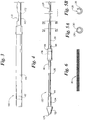
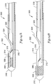
- FIGS. 1 and 2 illustrate plan views of a rapid exchange stent delivery catheter system 10 having features which may be employed in embodiments of the present invention.
- the rapid exchange stent delivery catheter system 10 includes a rapid exchange catheter 100 which is advanced over a guidewire 30 (shown in phantom) to deliver and deploy a self-expanding stent 20 in a bodily lumen.
- the rapid exchange stent delivery catheter system 10 is suitable for biliary and/or gastrointestinal applications.
- the rapid exchange stent delivery catheter system 10 is sized to fit within an endoscope (not shown) and to navigate to the desired site in the biliary tract.
- the rapid exchange stent delivery catheter system 10 is sized to fit within an introducer sheath (not shown) and/or a guide catheter (not shown) to navigate to the desired vascular site.
- the rapid exchange stent delivery catheter system is sized to fit within an endoscope (not shown), to navigate to the desired enteral site, and to enable expansion of a self-expanding stent (such as a Wallstent® produced by Boston Scientific Corporation) sufficiently large to palliate an enteral stricture and allow digestive processes to occur.
- a self-expanding stent such as a Wallstent® produced by Boston Scientific Corporation
- the rapid exchange stent delivery catheter 100 includes an inner tubular member 120 slidably disposed in an outer tubular member 140.
- the outer tubular member 140 includes a lumen (not visible) extending therethrough to slidably accommodate the inner tubular member 120.
- the inner tubular member 120 includes a guidewire lumen 130 (shown in FIG. 5A ) extending through a distal portion thereof to accommodate the guidewire 30.
- the guidewire 30 exits through a guidewire opening 170 in the outer tubular member 140 as will be discussed in greater detail with reference to FIGS. 3 , 7A and 7B .
- the guidewire 30 extends through a relatively short guidewire lumen and enters through a distal guidewire opening in the inner tubular member 120, as will be discussed in greater detail with reference to FIGS. 4, 5A and 5B .
- the device 100 may be inserted over the guidewire 30 from the tip end first.
- a proximal handle 122 is connected to a proximal portion 124 of the inner tubular member 120.
- a distal handle 142 is connected to a proximal portion 144 of the outer tubular member 140.
- the distal handle 142 may be longitudinally displaced relative to the proximal handle 122 to selectively expose or cover the self-expanding stent 20, which is disposed about a distal portion of the inner tubular member 120.
- the distal handle 142 has been longitudinally displaced in the distal direction relative to proximal handle 122 such that the outer tubular member 140 covers the self-expanding stent 20.
- the distal handle 142 has been longitudinally displaced in the proximal direction relative to proximal handle 122 to retract the outer tubular member 140 relative to the inner tubular member 120 to expose and deploy the self- expanding stent 20.
- the outer tubular member 140 includes, from the proximal end to the distal end, a proximal portion 144, a main outer portion (not visible) a guidewire sleeve 160 and a distal outer portion 146.
- the proximal end of the proximal outer portion 144 is connected to the distal handle 142.
- the distal handle 142 may be injection molded over the proximal outer portion 144.
- the distal end of the proximal outer portion 144 is connected to the proximal end of the main outer portion (not visible).
- the distal end of the main outer portion (not visible) is connected to the proximal end of the guidewire sleeve 160, and the distal end of the guidewire sleeve 160 is connected to the proximal end of the distal outer portion 146.
- the various portions of the outer tubular member 140 may be connected by adhesive, by thermal means or by any other suitable means known to those skilled in the art.
- the proximal outer portion 144 may be formed of PEBAX®, having a length of approximately 8.0 inches (20.3 cm), an outside profile of approximately 0.120 inches (9F) (0.30 cm), and an inside diameter of approximately 0.083 inches (0.21 cm).
- the guidewire sleeve 160 is discussed in greater detail with reference to FIGS. 7A and 7B .
- the main outer portion (not visible) may be formed of PEBAX®/wire braid/PTFE composite, having a length of approximately 55.0 inches (140 cm), an outside profile of approximately 6F (0.079 inches), and an inside diameter of approximately 0.057 inches (0.145 cm).
- the distal outer portion 146 may be formed of PEBAX®/wire braid/PTFE composite, having a length of approximately 10.6 inches (27 cm), an outside profile of approximately 8F (0.105 inches), and an inside diameter of approximately 0.090 inches (0.229 cm).
- the proximal outer portion 144 may be formed of PEBAX®, having a length of approximately 8.0 inches (20.3 cm), an outside profile of approximately 0.120 inches (9F) (0.30 cm), and an inside diameter of approximately 0.083 inches (0.21 cm).
- the main outer portion (not visible) may be formed of PEBAX®/wire braid/PTFE composite, having a length of approximately 55.0 inches (140 cm), an outside profile range of approximately 6F-8F (0.079-0.105 inches), and an inside diameter of approximately 0.057 inches (0.145 cm).
- the distal outer portion 146 may be formed of PEBAX®/wire braid/PTFE composite, having a length of approximately 10.6 inches (27 cm), an outside profile of approximately 10F (0.131 inches), and an inside diameter of approximately 0.113 inches (0.286 cm). Depending upon the size of the stricture to be palliated, longer or larger distal outer portions may be used as well.
- a radiopaque marker band 42 may be disposed adjacent the distal end of the distal outer portion 146 to facilitate radiographic placement of the catheter 100 and to radiographically indicate the position of the outer tubular member 140 relative to the inner tubular member 120 to aid in deploying the self-expanding stent 20.
- the inner tubular member 120 includes a distal inner portion 126 connected to the distal end of the proximal inner portion 124.
- the proximal inner portion 124 and the distal inner portion 126 are essentially the same, except the proximal inner portion 124 is reinforced with a stainless steel hypotube.
- the inner portions 124/126 may be formed of PEEK, having a length of approximately 88.6 inches (225 cm), an outside profile of approximately 0.052 inches (0.13 cm), and an inside diameter of approximately 0.037 inches (0.094 cm).
- a jacket formed of LDPE having a length of approximately 5.9 inches (15 cm), an outside profile of approximately 0.080 inches (0.20 cm), and an inside diameter of approximately 0.055 inches (0.14 cm) may be disposed about the inner member 120 to consume the clearance between the inner member 120 and the outer member 140 proximal of the stent 20 to prevent kinking.
- the various portions of the inner tubular member 120 may be connected by adhesive, by thermal means or by any other suitable means known to those skilled in the art.
- a distal head 132 is connected to the distal end of the distal inner portion 126 to limit distal displacement of the outer tubular member 140.
- a distal bond region 134 is disposed immediately proximal of the distal head 132.
- a holding sleeve 136 and a stent cup 138 prevent slippage of the stent 20.
- Radiopaque marker bands 44/48 are disposed on the distal inner portion 126 and are separated by a distance approximately equal to the length of the stent 20.
- the distal outer portion 146 of the outer tubular member 140 contains the self-expanding stent 20 during delivery.
- the distal inner portion 126 includes a proximal guidewire opening 128 and a distal guidewire opening 129.
- a guidewire lumen 130 extends between the proximal guidewire opening 128 and the distal guidewire opening 129 to accommodate the guidewire 30 therein.
- the proximal guidewire opening 128 has a length which is greater than the length of the guidewire opening 170 of the guidewire sleeve 160. The length of the proximal guidewire opening 128 is sufficient to allow longitudinal displacement of the outer tubular member 140 relative to the inner tubular member 120 to permit full exposure and deployment of the self-expanding stent 20.
- the length of the proximal guidewire opening 128 is preferably slightly longer than the length of the constrained portion of the stent 20 to avoid wedging the guidewire 30 between the inner tubular member 120 and the outer tubular member 140 prior to full deployment of the stent 20.
- the guidewire lumen 130 may be eccentrically positioned in the distal inner portion 126 as seen in FIGS. 5A and 5B .
- the upper wall may have a thickness of approximately 0.076 mm (0.003 inches) and the lower wall may have a thickness of approximately 0.279 mm (0.011 inches).
- the upper thinner wall portion may be removed (skived) to define the proximal guidewire opening 128.
- a solid mandrel may be inserted into the proximal lumen (not visible) of the inner tubular member 120 proximal of the guidewire opening 128 for improved column strength.
- the solid mandrel may be formed of stainless steel having an outside diameter of approximately 0.762 mm (0.03 inches) with a tapered end.
- a stainless steel hypotube (not shown) having an outside diameter of approximately 2.007 mm (0.079 inches) may be disposed about the proximal inner portion 124 for added column strength and durability.
- the proximal handle 122 may be injection molded over the proximal end of the hypotube and the proximal end of the proximal inner portion 124.
- a distal radiopaque marker 44 is disposed on the distal inner portion 126 to radiographically mark the distal end of the stent 20.
- a proximal radiopaque marker 48 is disposed on the distal inner portion 126 to radiographically mark the proximal end of the stent 20.
- a mid radiopaque marker 46 is disposed on the distal inner portion 126 distal of the holding sleeve 136 to radiographically facilitate deployment of the stent 20.
- the stent 20 may comprise any self-expanding stent suitable for enteral, biliary or intravascular applications.
- the self-expanding stent 20 may comprise a metallic stent commercially available from Boston Scientific Corporation under the trade name Wallstent®.
- the guidewire sleeve 160 includes a proximal portion 164, a distal portion 162 and a lumen 166 extending therethrough.
- the distal portion 162 is flared to fit over and be connected to the distal outer portion 146.
- the proximal portion 164 is sized to fit within and be connected to the main outer portion.
- a guidewire opening 170 extends through the exterior wall of the guidewire sleeve 160.
- a ramp 172 extends from the exterior wall into the lumen 166. When assembled, the ramp 172 extends through the proximal guidewire opening 128 of the inner tubular member 120 and into the guidewire lumen 130. The ramp 172 is moveable within the proximal guidewire opening 128 to facilitate a smooth transition of the guidewire 30 from the guidewire lumen 130 to exterior of the catheter 100, regardless of the position of the outer tubular member 140 relative to the inner tubular member 120.
- the guidewire sleeve 160 may have a length of approximately 25.4 mm (1.0 inch), a distal outside diameter of approximately 3.099 mm (0.122 inches), a proximal outside diameter of approximately 2.210 mm (0.087 inches), a distal inside diameter of approximately 2.718 mm (0.107 inches), and a proximal inside diameter of approximately 1.778 mm (0.07 inches).
- the ramp 172 may be an integral extension of the exterior wall of the guidewire sleeve 160 and may have a length of approximately 2.286 mm (0.09 inches) and a width of approximately 12.7 mm (0.5 inches). The ramp 172 may extend into the lumen 166 at an angle of approximately 30 degrees.
- the guidewire sleeve 160 may be an integral part of the outer tubular member 140 but is preferably a separately manufactured component.
- the guidewire sleeve 160 may be formed of injection molded nylon or polypropylene. If the guidewire sleeve 160 is injection molded, manufacturing artifacts such as hole 168 may be filled or removed depending on the particular application. By manufacturing the guidewire sleeve 160 separately, more manufacturing flexibility and efficiency are achieved.
- the guidewire sleeve 160 may be made of a material that is not melt sensitive or that is readily bonded to facilitate connection to other catheter components using adhesive or thermal means.
- the guidewire sleeve 160 may be inspected prior entering the production floor to eliminate non-conforming parts and increase efficiency. Further, the dimensions may be controlled better to provide greater consistency at bond sites.
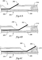
- FIGS. 8A-8C arc longitudinal sectional views of a guidewire entry port as a self-expanding stent is released for an example corresponding to FIG. 1 .
- the illustrative guidewire entry port 200 is shown having a guidewire 202 exiting the catheter 204.
- the catheter has an outer member 206, an inner member 208, and a mandrel 210.
- the mandrel 210 may be disposed, as noted above, within the inner member 206 to provide improved column strength over a proximal portion of the catheter.
- Figure 8A corresponds to a configuration wherein a stent is constrained by the outer member 206.
- the mandrel 210 which is within the inner member 206, slides distally as well, as shown in Figure 8B.
- Figure 8C illustrates the configuration at the guidewire entry port 200 when the stent is fully deployed. As shown, the mandrel 210 must be sized to stop short of the entry port 200 to avoid interfering with the guidewire 202.
- a potential problem for the configuration of Figures 8A-8C is the distance between the distal end of the mandrel 210 and the guidewire entry port 200.
- the mandrel 210 is included to provide added column strength, but does not span the guidewire entry port 200.
- the outer member 206 is cut at the guidewire entry port 200, weakening the outer member 206.
- the inner member 208 is skived across the guidewire entry port 200, and is, therefore, also weakened.
- a further problem may occur when the stent is to be deployed.
- the catheter when relative pushing and pulling occurs between the inner member 208 and outer member 206, there is a potential for the catheter to deflect, causing inaccurate stent placement.
- the skived inner member 208 can deflect at a location in the skived region (particularly to the side that is skived), causing the distal end of the catheter to deflect.
- a decision may be made to seek to push the outer member distally to pull the stent back into a restrained position. Again, such a step can create lateral deflection.
- the guidewire At locations where the guidewire is disposed within the catheter, it is easier to retain a straight configuration, because the guidewire provides at least some support to the catheter. However, this support is not as easily provided proximate to and proximal of the guidewire port.
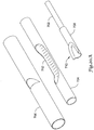
- FIG. 9 is an isometric view of a guidewire entry ramp for another embodiment according to the invention having a ramp-ended mandrel.
- the catheter 240 includes a guidewire entry port 242, outer member 246, inner member 248, and a mandrel 250 having a slanted or ramp-shaped distal end. While the FIG. 7A illustrates forming a ramp using the outer member, FIG. 9 instead uses a specially shaped mandrel 250. This modification allows for a simpler treatment of the outer member 246.
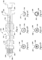
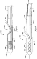
- FIG. 10 is a plan and partial cut-away view of a rapid exchange stent delivery catheter according to FIG. 9 .
- the catheter 240 is shown having a guidewire port 242 which allows a guidewire 244 to exit the catheter 240.
- the inner member 248 is shown as carrying a stent 252 (shown by cutting away a portion of the outer member 246) and having a distal cap 256.
- the inner member 248 may be crimped or skived across the guidewire port 242. As illustrated by the placement of the guidewire 244, the inner member 248 does include an opening allowing entry of the guidewire 244 thereto and passage through a lumen in the inner member 248 to the distal end of the catheter 240.
- the catheter 240 also includes two proximal end handles, a first handle 258 coupled to the outer member 246 and a second handle 260 coupled to the inner member 248.
- the handles 258, 260 allow a physician to easily slide the inner member 248 with respect to the outer member 246.
- the mandrel 250 is attached to the first handle 258, such that it is coupled to the outer member 246 rather than the inner member 248.
- FIGS. 11A-11C are longitudinal sectional views of a guidewire entry port as a self-expanding stent is released for an embodiment corresponding to FIG. 10 .
- Figure 11A shows the guidewire 244 exiting the guidewire port 242 with the mandrel 250 in providing an exit ramp.
- the mandrel 250 does not move with respect to the guidewire port 242, since the port 242 and the mandrel 250 are coupled directly to the outer member 246.
- the mandrel 250 does not move with respect to the outer member 246 and the guidewire port 242.
- the added pushability provided by the mandrel 250 is made usable during insertion and advancement of the catheter 240, before deployment of the stent 252.
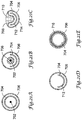
- FIGS. 12A-12F are cross sectional views taken along lines A-A, B-B, C-C, and D,E,F-D,E,F, respectively, in FIG. 10 .
- FIGS. 12D-12F are alternatives to one another illustrating different proximal configurations for the mandrel 250 and the inner member 248.
- the outer member 246 and inner member 248 are generally coaxial.
- the guidewire 244 passes through a lumen defined by the inner member 248.
- FIG. 12B is closer to the guidewire port 242 ( FIG. 10 ), and shows that a portion of the inner member 248 has been skived off or otherwise removed to allow the guidewire 244 to enter the lumen of the inner member 248.
- both the inner member 248 and the outer member 246 have a generally crescent shape allowing the guidewire 244 to enter the catheter.
- FIGS. 12D-12F Several alternative configurations proximal of the guidewire port 242 ( FIG. 10 ) are shown in FIGS. 12D-12F .
- FIG. 12D corresponds generally to that shown in FIG. 10 , illustrating that the inner member 248 resumes a tubular shape proximal of the guidewire port 242 ( FIG. 10 ) and the mandrel 250 passes therethrough.
- the inner member 248 may be skived or otherwise have a portion removed near the proximal end of the inner member 248. This allows the mandrel 250 to pass outside the inner member 248 and couple to either the outer member 246 or the first handle 258 ( FIG. 10 ). This coupling limits relative axial movement of the outer member 246 and the mandrel 250.
- FIG. 12E corresponds to a first alternative configuration where the inner member 248 has a crescent shape (for example, by removing a portion of a hypotube) proximal of the guidewire port 242 ( FIG. 10 ) to the proximal end, at least, of the mandrel 250.
- FIG. 12F Another alternative is shown in FIG. 12F , where the inner member 248 is shown as a push or core wire.
- the mandrel 250 may be shaped to secure the inner member 248 wire in an un-kinked or bent configuration, as shown.
- the wire portion of the inner member 248 may be attached by any of a number of methods (i.e., welding, brazing, or adhesive, for example) to the more distal crescent-shaped and/or tubular portions of the inner member 248.
- welding brazing
- adhesive for example
- mandrel 250 is shown as being significantly larger than the inner member 248 for purposes of illustration, this need not be the case.
- FIG. 13 is a longitudinal sectional view of a guidewire entry port and distal end of a rapid exchange stent delivery catheter 280 having a proximal push wire.
- the guidewire entry port 282 allows a guidewire 284 to exit the catheter.
- An inner member includes a distal tubular section 286 and a proximal push member 288 which is illustrated in the form of a wire.
- the outer member includes an outer distal member 290, from which a flap has been used to make a ramp 292. The outer distal member 290 is secured to an outer proximal member 294.
- the outer proximal member 294 is a smaller bore hypotube, and the outer distal member 290 is a larger bore polymeric member.
- the outer proximal member 294 takes the form of a dual lumen side-by-side elongate member.
- a mandrel 296 may optionally be included.
- the several integral parts of the catheter 280 may be secured together by any of a number of methods, including thermal and adhesive processes.
- FIGS. 14A-14B are longitudinal sectional views of another guidewire entry port and distal end of a catheter having a ramp-shaped mandrel and a proximal push wire.
- the catheter 300 includes a guidewire port 302 where a guidewire 304 exits the catheter 300.
- An inner member includes a distal tubular member 306 on which a stent 308 is disposed, and which ends in a distal head 310.
- the distal tubular member 306 is attached on its outside, near its proximal end, to a push wire 312 that extends toward the proximal end (not shown) of the catheter 300.
- a distal outer member 314 is illustrated as well, with the outer member 314 having been skived or trimmed to remove a portion for creating the guidewire port 302, as shown at 316.
- the distal outer member 314 is attached to a proximal outer member 318.
- a mandrel 320 having a ramp-shaped distal end is included, and may be secured in a manner which causes it to move axially in a one-to-one ratio with the outer members 314, 318.
- a handle at the proximal end (not shown) of the catheter 300 is attached to both the mandrel 320 and the proximal outer member 318.
- the mandrel 320 may be secured to the proximal outer member 318 at some location along the length thereof. For example, if the proximal outer member 318 is provided as a hypotube, a metal mandrel 320 may be brazed or welded to the hypotube.
- One known problem for some rapid exchange catheters having inner and outer members that are slidable with respect to one another is alignment. If the inner member is a tubular member along the length that crosses the guidewire port, then the opening in the inner member for the guidewire exit must align with the opening of the outer member for the guidewire exit port. Otherwise, the guidewire is subject to added friction or pinching at the guidewire exit port, making relative movement between the guidewire and the catheter difficult. However, if the inner member is not a tubular member across the guidewire port, which is the case for several embodiments herein (including FIGS. 14A-14B ), the alignment problem is alleviated.
- FIG. 14A illustrates the catheter 300 in a non-deployed configuration.
- the inner tubular member 306 is advanced by the combination of a pushing force applied to the push wire 312 and a pulling force applied to the proximal outer member 318.
- the stent 308 passes the distal end of the outer member 314, it self-expands to unblock or palliate a stricture in a body lumen, as shown in FIG. 14B .
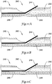
- FIG. 15 is a longitudinal sectional view of yet another guidewire entry port and distal end of a rapid exchange stent delivery catheter.
- the catheter 400 includes a guidewire port 402 allowing a guidewire 404 to pass from within the catheter 400 to the exterior.
- a distal tubular member 406 carries a stent 408 and is attached to a distal head 410.
- a push wire 412 is attached to the distal tubular member 406.
- a distal outer member 414 has a ramp formed therein at the guidewire port 402.
- the ramp may be formed by any number of methods.
- the ramp can be formed by making a partial circumferential cut in the distal outer member 414, making a longitudinal slit in the distal outer member extending proximally from the partial circumferential cut, using one or more mandrels to hold the cut portions in a desired ramp shape, and applying heat to cause melting or at least re-flow of the distal outer member 414 material.
- the distal outer member 414 may be held in a crimped configuration and heated to form the ramp.
- the pushwires 288, 312 attach to the outside of the distal tubular members 286, 306.
- the pushwire 412 attaches to the inside of the distal tubular member 406.
- this inner attachment allows the distal tubular member 406 to be sized more closely to the size of the distal outer member 414.
- the pushwire 412 is used to transmit the pushing force, allowing the distal tubular member itself to be a very thin-walled piece.
- FIG. 16 is a longitudinal sectional view of still another guidewire entry port and distal end of a rapid exchange stent delivery catheter.
- the catheter 500 includes a guidewire port 502 allowing a guidewire 504 to exit the catheter 500.
- a distal inner member 506 carries a stent 508 and extends to a distal head 510.
- the distal inner member 506 is coupled to a pushwire 512, which spans the guidewire port 502 and couples to a proximal member 514 which is shown in the form of a round elongate member that may be hollow, filled, or solid.
- the outside of the catheter 500 includes three main parts, a distal outer member 516, a midshaft 518, and a proximal member 520.
- the ramp for the guidewire port 502 is defined by the midshaft 518, which may be shaped by any number of methods such as the cut, slit and re-flow or crimp and melt methods discussed above with respect to FIG. 15 .
- the distal outer member 516 may be attached during the steps of forming the ramp, or may be placed later.
- the midshaft 518 is also attached to the proximal member 520 which, in several embodiments, is a hypotube.
- the catheters may be considered "convertible".
- the catheter 500 can be initially placed over a first guidewire that exits the catheter at the guidewire port 502. If the first guidewire proves to be unsuitable for the particular lesion or stricture being treated (for example, it may be too flexible to pass a stricture, or may not be suitable for precise advancement), the guidewire may be withdrawn and a second guidewire advanced through the proximal inner member 514 to the ramp.
- the inner members are movable with respect to the outer member; the ramp need not completely or tightly seal (indeed, too tight of a seal may impede relative movement needed to deploy the stent 508) thereabout.
- blood is a relatively sticky fluid, so it is useful to provide tight seals to keep the blood from entering guidewire lumens and limiting guidewire movement.
- this problem is greatly reduced in biliary applications so that tighter seals are not always a necessity (though the fluids tend to be more corrosive and can create other problems).
- the second guidewire will advance to the back side of the ramp, it will be directed by the ramp to the location where the inner member (i.e., push wire 512) passes the ramp, and may pass by the ramp by passing adjacent the inner member (push wire 512).
- the second guidewire can then be advanced to the distal end of the catheter 500.
- FIG. 17 is an exploded view of a ramp member including a band to provide a guidewire entry port.
- the mandrel/ramp member 530 is formed having a mandrel portion 532 coupled at its distal end of a ramp piece 534 having a ramp 536.
- a band 538 is included.
- the ramp 536 and band 538 are secured about the outer member 540, which at least partially encloses the inner member 542.
- the band 538 may be secured to the ramp 536 by any suitable manner, including the application of adhesives, welding, and/or snap fit.
- FIG. 19 is a longitudinal sectional view of a guidewire entry port and distal end of a rapid exchange stent delivery catheter including an intermediate tubular member across the guidewire entry port.
- the catheter 600 includes a guidewire port 602 allowing a guidewire 604 to exit the catheter 600.
- a distal tubular member 606 carries a stent 608 and ends in a distal head 610.
- the distal tubular member 606 is attached to a push wire 612 that passes to the proximal side of the guidewire port 602.
- the distal outer member 614 is cut to remove a portion at the guidewire port 602.
- the proximal end of the distal outer member 614 is attached to a proximal outer member 616 that may be a polymeric or reinforced polymeric tube, but is preferably a hypotube.
- a proximal outer member 616 may be a polymeric or reinforced polymeric tube, but is preferably a hypotube.
- the proximal end of the distal outer member 614 has been crimped or slit and compressed against the distal end of the proximal outer member 616 to achieve attachment thereto, as shown by the taper at 622. This enables use of a lower profile proximal outer member 616.
- An intermediate tubular member 618 is also illustrated.
- the intermediate tubular member 618 is used to aid in making the ramp 620 that directs the guidewire 604 out of the catheter 600.
- a first mandrel is passed through the intermediate tubular member 618, and the intermediate tubular member 618 is placed within the distal outer member 614.
- a partial circumferential cut is made in the distal outer member 614 to define the distal edge of the guidewire port 602. Proximally of the cut, the distal outer member 614 is then crimped down to the intermediate tubular member 618.
- Additional mandrels may be placed to retain the patency of the distal outer member 614 during the next step, which includes heating the distal outer member 614 in the region of the ramp 620 to cause melting and/or reflow of the catheter 600 material.
- the intermediate tubular member 618 aids in providing pushability for the whole catheter 600, as well as providing directional control over the push wire 612 across the guidewire port 602.
- FIGS. 20A and 20B provide an exploded and side section view of another illustrative embodiment wherein a ramp is coupled to an inner mandrel and extends out to the outer member.
- the catheter 700 includes a mandrel 702, inner member 704 and outer member 706.
- the distal end of the mandrel 702 is connected to a ramp member 708 including guidewire ramp 710.
- the inner member 704 includes a skived portion 712.
- the ramp member 708 is secured to both the mandrel 702 and the outer member 706.
- the mandrel 702 may have an unsecured proximal end, and is provided for stiffness support.
- the mandrel 702 may be secured near its proximal end to the outer member 706, or to an element secured to the outer member 706.
- FIGS. 21A-21E are cross-sectional views taken along lines 21A-21A, 21B-21B, 21C-21C, 21D-21D, and 21E-21E, respectively, of FIG. 20B .
- the mandrel 702 is disposed within the inner member 704 and outer member 706.
- the mandrel 702 has been secured to the ramp member 708 near its distal end, at a location corresponding to the skived portion 712 of the inner member.
- the ramp member 708 may be secured to the mandrel 702 by any suitable method, for example, using heat, welding, adhesives, and/or insert molding, for example.
- the ramp member 708 and the guidewire ramp 710 can be seen.
- the ramp member 708 is secured to the outer member 706 by any suitable method.
- the illustrative embodiment of FIG. 21C shows the ramp member 708 secured to the outer member 706 using a lap joint that is heat welded together, for example, with the use of a crescent shaped mandrel and a hot die, or by a laser method. Alternatively, an adhesive may also be used. Because the ramp member 708 is secured to both the mandrel 702 ( FIG. 21B ) and the outer member 706, there is no variable "gap" from the distal end of the mandrel 702 to the ramp 710 and/or the opening or skived portion 714 of the outer member 706.
- the outer member 706 is disposed about the skived portion 712 of the inner member 704.
- the skived portion 712 of the inner member 704 extends for at least the length of a stent to be delivered such that the inner member 704 is slidable with respect to the ramp member 710 along the skived portion 712.
- the inner member 704 again has a generally circular shape.
- the inner member 704 may be a multi-piece member having at least the skived portion comprising a hypotube member, with other portions being hypotubes, tubular polymeric pieces, or one or more polymeric pieces including braided support members.
- a stent 716 is shown disposed between the inner member 704 and outer member 706.
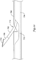
- FIG. 22 illustrates a method of assembling the illustrative embodiment of Figures 20A-20B and 21A-21E .
- the inner and outer members are aligned such that the skived portion 712 of the inner member 704 aligns generally with a relatively short opening 714 in the outer member 706.
- the proximal end of the mandrel 702 is inserted and advanced in a proximal direction through the opening 714 such that the proximal end of the mandrel 702 passes into the inner member 704.
- the mandrel 702 is moved proximally until the ramp member 708 enters the opening 714 and the ramp 710 engages the outer member 706.
Landscapes
- Health & Medical Sciences (AREA)
- Engineering & Computer Science (AREA)
- Biomedical Technology (AREA)
- Life Sciences & Earth Sciences (AREA)
- Veterinary Medicine (AREA)
- Animal Behavior & Ethology (AREA)
- Heart & Thoracic Surgery (AREA)
- Public Health (AREA)
- General Health & Medical Sciences (AREA)
- Oral & Maxillofacial Surgery (AREA)
- Transplantation (AREA)
- Vascular Medicine (AREA)
- Cardiology (AREA)
- Biophysics (AREA)
- Pulmonology (AREA)
- Anesthesiology (AREA)
- Hematology (AREA)
- Media Introduction/Drainage Providing Device (AREA)
- Materials For Medical Uses (AREA)
Claims (10)
- Cathéter de type à échange rapide (240, 300, 700) conçu pour placer une endoprothèse auto-expansible (252, 308, 716), le cathéter comprenant :un élément extérieur (246, 314, 540, 706) présentant une partie proximale, une partie distale et un orifice de fil-guide (242, 302) entre elles, la partie distale conçue pour couvrir une endoprothèse auto-expansible ;un élément intérieur (248, 306, 542, 704) positionné à l'intérieur d'une lumière définie par l'élément extérieur, l'élément intérieur présentant une partie proximale et une partie distale tubulaire, la partie distale tubulaire définissant une lumière fil-guide pour passer un fil-guide, la partie distale conçue pour recevoir une endoprothèse auto-expansible sur elle ; etun élément mandrin (250, 320, 530, 702) présentant une rampe (536, 710) à son extrémité distale, une partie de l'élément mandrin positionnée à l'intérieur de l'élément extérieur ;dans lequel l'élément extérieur (246, 314, 540, 706) est mobile par rapport à l'élément intérieur (248, 306, 542, 704).
- Cathéter selon la revendication 1, dans lequel le mandrin est disposé à l'intérieur de l'élément extérieur de telle sorte que la rampe soit située près de l'orifice de fil-guide de l'élément extérieur.
- Cathéter selon la revendication 1, dans lequel les élément intérieur, élément extérieur et mandrin sont formés et dimensionnés de telle sorte que le mandrin et l'élément intérieur s'étendent à l'intérieur de l'élément extérieur.
- Cathéter selon la revendication 3, dans lequel le mandrin s'ajuste à l'intérieur de l'élément intérieur pour une partie proximale de la longueur de l'élément intérieur.
- Cathéter selon la revendication 3, dans lequel le mandrin ne s'ajuste pas à l'intérieur de la partie proximale de l'élément intérieur.
- Cathéter selon la revendication 3, dans lequel le mandrin et la partie proximale de l'élément intérieur se trouvent à l'intérieur de l'élément extérieur d'une manière en général côte à côte.
- Cathéter selon la revendication 1, dans lequel l'élément extérieur et le mandrin demeurent en général dans la même configuration l'un par rapport à l'autre lorsque l'élément intérieur est déplacé par rapport à l'élément extérieur.
- Cathéter selon la revendication 1, dans lequel l'élément extérieur et le mandrin sont couplés ensemble pour empêcher un mouvement axial relatif de l'élément extérieur et du mandrin.
- Cathéter selon la revendication 1, dans lequel l'élément extérieur et le mandrin sont couplés à un élément commun de telle sorte que le mouvement axial entre l'élément extérieur et le mandrin soit empêché.
- Cathéter selon la revendication 1, comprenant en outre un premier appareil proximal et un second appareil proximal, le premier appareil proximal fixé contre l'extrémité proximale de l'élément extérieur et l'extrémité proximale du mandrin, le second appareil proximal fixé contre l'extrémité proximale de l'élément intérieur.
Priority Applications (1)
| Application Number | Priority Date | Filing Date | Title |
|---|---|---|---|
| EP18207489.8A EP3488827B1 (fr) | 2007-02-05 | 2008-01-31 | Système d'administration de stent entérique de type à échange rapide |
Applications Claiming Priority (3)
| Application Number | Priority Date | Filing Date | Title |
|---|---|---|---|
| US88818907P | 2007-02-05 | 2007-02-05 | |
| US12/022,337 US7815601B2 (en) | 2007-02-05 | 2008-01-30 | Rapid exchange enteral stent delivery system |
| PCT/US2008/052622 WO2009105089A2 (fr) | 2007-02-05 | 2008-01-31 | Système d'administration de stent entérique de type à échange rapide |
Related Child Applications (2)
| Application Number | Title | Priority Date | Filing Date |
|---|---|---|---|
| EP18207489.8A Division EP3488827B1 (fr) | 2007-02-05 | 2008-01-31 | Système d'administration de stent entérique de type à échange rapide |
| EP18207489.8A Division-Into EP3488827B1 (fr) | 2007-02-05 | 2008-01-31 | Système d'administration de stent entérique de type à échange rapide |
Publications (2)
| Publication Number | Publication Date |
|---|---|
| EP2117475A2 EP2117475A2 (fr) | 2009-11-18 |
| EP2117475B1 true EP2117475B1 (fr) | 2018-12-26 |
Family
ID=39676797
Family Applications (2)
| Application Number | Title | Priority Date | Filing Date |
|---|---|---|---|
| EP18207489.8A Active EP3488827B1 (fr) | 2007-02-05 | 2008-01-31 | Système d'administration de stent entérique de type à échange rapide |
| EP08872019.8A Active EP2117475B1 (fr) | 2007-02-05 | 2008-01-31 | Système d'administration de stent entérique de type à échange rapide |
Family Applications Before (1)
| Application Number | Title | Priority Date | Filing Date |
|---|---|---|---|
| EP18207489.8A Active EP3488827B1 (fr) | 2007-02-05 | 2008-01-31 | Système d'administration de stent entérique de type à échange rapide |
Country Status (6)
| Country | Link |
|---|---|
| US (7) | US7815601B2 (fr) |
| EP (2) | EP3488827B1 (fr) |
| JP (1) | JP5595046B2 (fr) |
| AU (1) | AU2008349766A1 (fr) |
| CA (1) | CA2693071C (fr) |
| WO (1) | WO2009105089A2 (fr) |
Families Citing this family (36)
| Publication number | Priority date | Publication date | Assignee | Title |
|---|---|---|---|---|
| US6592549B2 (en) * | 2001-03-14 | 2003-07-15 | Scimed Life Systems, Inc. | Rapid exchange stent delivery system and associated components |
| US7815601B2 (en) | 2007-02-05 | 2010-10-19 | Boston Scientific Scimed, Inc. | Rapid exchange enteral stent delivery system |
| WO2009105699A1 (fr) | 2008-02-22 | 2009-08-27 | Endologix, Inc. | Conception et procédé de mise en place d’un greffon ou d’un système de greffons |
| CA2739841A1 (fr) * | 2008-10-10 | 2010-04-15 | Nexeon Medsystems, Inc. | Systeme de catheter limitant les stocks |
| JP5629871B2 (ja) | 2009-04-28 | 2014-11-26 | エンドロジックス、インク | 移植片あるいは移植片システムを配置する装置および方法 |
| US8771335B2 (en) * | 2009-09-21 | 2014-07-08 | Boston Scientific Scimed, Inc. | Rapid exchange stent delivery system |
| JP5671228B2 (ja) * | 2009-12-14 | 2015-02-18 | テルモ株式会社 | バルーンカテーテル |
| WO2012054709A1 (fr) * | 2010-10-20 | 2012-04-26 | Stryker Corporation | Cathéter de pose de stent ayant des capacités d'échange rapide |
| JP6261339B2 (ja) | 2010-11-02 | 2018-01-17 | エンドロジックス、インク | グラフトまたはグラフトシステムの配置の器具および方法 |
| CN102525698A (zh) * | 2010-12-31 | 2012-07-04 | 微创医疗器械(上海)有限公司 | 一种介入医疗器械输送和释放装置 |
| JP5726563B2 (ja) * | 2011-02-17 | 2015-06-03 | テルモ株式会社 | ステントデリバリーシステム |
| EP2689753B1 (fr) | 2011-03-25 | 2016-12-21 | Terumo Kabushiki Kaisha | Système de mise en place de stent |
| WO2013003450A1 (fr) | 2011-06-27 | 2013-01-03 | Boston Scientific Scimed, Inc. | Systèmes de pose de stent et procédés de fabrication et d'utilisation de systèmes de pose de stent |
| CA2920641C (fr) | 2013-08-26 | 2022-08-30 | Merit Medical Systems, Inc. | Guide sans gaine, dilatateur a echange rapide et procedes associes |
| USD767127S1 (en) * | 2013-10-14 | 2016-09-20 | Tsk Laboratory Europe B.V. | Needle with dome shaped tip |
| WO2015107506A2 (fr) * | 2014-01-20 | 2015-07-23 | Baylis Medical Company Inc. | Cathéter de ré-entrée à pointe pliable |
| DE202015009843U1 (de) * | 2014-06-18 | 2020-08-31 | Boston Scientific Scimed, Inc. | Gallengang-Stent |
| US10383683B2 (en) * | 2014-10-20 | 2019-08-20 | Asahi Medical Technologies, Inc. | Redirecting delivery catheter and methods of use thereof |
| JP6329101B2 (ja) * | 2015-04-15 | 2018-05-23 | オリンパス株式会社 | 内視鏡用処置具および内視鏡用処置具の製造方法 |
| EP4417169A2 (fr) | 2015-06-30 | 2024-08-21 | Endologix LLC | Ensemble de verrouillage pour coupler un fil-guide à un système de distribution |
| JP2018130312A (ja) * | 2017-02-15 | 2018-08-23 | オリンパス株式会社 | 医療用カテーテルチューブ |
| JP2021526041A (ja) | 2018-06-05 | 2021-09-30 | メドトロニック・ヴァスキュラー・インコーポレーテッド | 医療用カテーテル |
| WO2019236741A1 (fr) | 2018-06-05 | 2019-12-12 | Medtronic Vascular, Inc. | Cathéter médical |
| WO2019236737A1 (fr) | 2018-06-05 | 2019-12-12 | Medtronic Vascular, Inc. | Cathéter comprenant une poignée de poussée coulissante |
| CN109044525B (zh) * | 2018-09-11 | 2024-06-04 | 南微医学科技股份有限公司 | 一种导丝接头 |
| WO2020217463A1 (fr) * | 2019-04-26 | 2020-10-29 | オリンパス株式会社 | Cathéter et système de pose d'endoprothèse |
| CN115135286A (zh) * | 2020-02-20 | 2022-09-30 | 奥林巴斯株式会社 | 支架输送系统、内窥镜系统及支架留置方法 |
| CN115135285A (zh) * | 2020-02-20 | 2022-09-30 | 奥林巴斯株式会社 | 支架输送系统、内窥镜系统及支架留置方法 |
| DE102020119235A1 (de) | 2020-07-21 | 2022-01-27 | FUJIFILM medwork GmbH | Endoskopische Vorrichtung zum Implantieren eines medizinischen Stents in einen Ductus eines Gastrointestinaltraktes |
| CN112843426A (zh) * | 2020-08-05 | 2021-05-28 | 中国人民解放军海军军医大学第一附属医院 | 单通道双出口的血管鞘 |
| CN113171176B (zh) * | 2021-06-28 | 2021-10-01 | 北京纳通医学研究院有限公司 | 机械臂系统 |
| CN113616397A (zh) * | 2021-08-27 | 2021-11-09 | 苏州中天医疗器械科技有限公司 | 一种整体交换式球囊支架安装装置及支架安装方法 |
| CN113599037A (zh) * | 2021-08-27 | 2021-11-05 | 苏州中天医疗器械科技有限公司 | 一种快速交换式球囊支架安装装置及支架安装方法 |
| US20230190502A1 (en) * | 2021-12-20 | 2023-06-22 | Medtronic Vascular, Inc. | Delivery system for delivering a cardiovascular device |
| DE102022112498A1 (de) * | 2022-05-18 | 2023-11-23 | Medi-Globe Gmbh | Stent-Zuführeinrichtung und Endoskop mit einer solchen Stent-Zuführeinrichtung |
| EP4338779A1 (fr) * | 2022-09-16 | 2024-03-20 | Biotronik Ag | Orifice de sortie de fil de guidage, cathéter et procédés de fabrication associés |
Citations (3)
| Publication number | Priority date | Publication date | Assignee | Title |
|---|---|---|---|---|
| US6592549B2 (en) * | 2001-03-14 | 2003-07-15 | Scimed Life Systems, Inc. | Rapid exchange stent delivery system and associated components |
| US20040082935A1 (en) * | 1999-12-22 | 2004-04-29 | Lee Jeong Soo | Catheter having a reinforcing mandrel |
| US20070142821A1 (en) * | 2005-12-16 | 2007-06-21 | Medtronic Vascular, Inc. | Rapid exchange catheter having a uniform diameter exchange joint |
Family Cites Families (38)
| Publication number | Priority date | Publication date | Assignee | Title |
|---|---|---|---|---|
| SE445884B (sv) * | 1982-04-30 | 1986-07-28 | Medinvent Sa | Anordning for implantation av en rorformig protes |
| SE455834B (sv) * | 1986-10-31 | 1988-08-15 | Medinvent Sa | Anordning for transluminal implantation av en i huvudsak rorformig, radiellt expanderbar protes |
| US4748982A (en) | 1987-01-06 | 1988-06-07 | Advanced Cardiovascular Systems, Inc. | Reinforced balloon dilatation catheter with slitted exchange sleeve and method |
| SE8803444D0 (sv) * | 1988-09-28 | 1988-09-28 | Medinvent Sa | A device for transluminal implantation or extraction |
| US5100381A (en) * | 1989-11-13 | 1992-03-31 | Scimed Life Systems, Inc. | Angioplasty catheter |
| EP0408245B1 (fr) * | 1989-07-13 | 1994-03-02 | American Medical Systems, Inc. | Dispositif d'introduction d'un dilatateur |
| US5217482A (en) * | 1990-08-28 | 1993-06-08 | Scimed Life Systems, Inc. | Balloon catheter with distal guide wire lumen |
| CA2060067A1 (fr) * | 1991-01-28 | 1992-07-29 | Lilip Lau | Systeme de placement d'un extenseur |
| US5533968A (en) * | 1991-05-15 | 1996-07-09 | Advanced Cardiovascular Systems, Inc. | Low profile catheter with expandable outer tubular member |
| US6309379B1 (en) * | 1991-05-23 | 2001-10-30 | Lloyd K. Willard | Sheath for selective delivery of multiple intravascular devices and methods of use thereof |
| US5135535A (en) * | 1991-06-11 | 1992-08-04 | Advanced Cardiovascular Systems, Inc. | Catheter system with catheter and guidewire exchange |
| US5324269A (en) * | 1991-09-19 | 1994-06-28 | Baxter International Inc. | Fully exchangeable dual lumen over-the-wire dilatation catheter with rip seam |
| US5389087A (en) * | 1991-09-19 | 1995-02-14 | Baxter International Inc. | Fully exchangeable over-the-wire catheter with rip seam and gated side port |
| US5843028A (en) * | 1992-05-11 | 1998-12-01 | Medical Innovations Corporation | Multi-lumen endoscopic catheter |
| US5364376A (en) * | 1992-08-04 | 1994-11-15 | Danforth Biomedical Incorporated | Convertible catheter |
| ATE137656T1 (de) * | 1992-10-31 | 1996-05-15 | Schneider Europ Ag | Anordnung zum implantieren von selbstexpandierenden endoprothesen |
| DE9321003U1 (de) * | 1992-12-30 | 1995-08-10 | Schneider (Usa) Inc., Plymouth, Minn. | Vorrichtung zum Ausbringen von körperimplantierbaren Stents |
| US5360401A (en) * | 1993-02-18 | 1994-11-01 | Advanced Cardiovascular Systems, Inc. | Catheter for stent delivery |
| US5458605A (en) * | 1994-04-04 | 1995-10-17 | Advanced Cardiovascular Systems, Inc. | Coiled reinforced retractable sleeve for stent delivery catheter |
| US5743874A (en) * | 1994-08-29 | 1998-04-28 | Fischell; Robert E. | Integrated catheter for balloon angioplasty and stent delivery |
| US6059752A (en) * | 1994-12-09 | 2000-05-09 | Segal; Jerome | Mechanical apparatus and method for dilating and irradiating a site of treatment |
| US5643278A (en) * | 1995-04-06 | 1997-07-01 | Leocor, Inc. | Stent delivery system |
| EP0775470B1 (fr) * | 1995-11-14 | 1999-03-24 | Schneider (Europe) GmbH | Dispositif pour l'implantation d'une endoprothèse |
| US6077295A (en) * | 1996-07-15 | 2000-06-20 | Advanced Cardiovascular Systems, Inc. | Self-expanding stent delivery system |
| AU739710B2 (en) * | 1996-08-23 | 2001-10-18 | Boston Scientific Limited | Stent delivery system having stent securement apparatus |
| US5921971A (en) * | 1996-09-13 | 1999-07-13 | Boston Scientific Corporation | Single operator exchange biliary catheter |
| US6007522A (en) * | 1996-09-13 | 1999-12-28 | Boston Scientific Corporation | Single operator exchange biliary catheter |
| US6605057B2 (en) * | 1996-10-24 | 2003-08-12 | Medtronic Ave, Inc. | Reinforced monorail balloon catheter |
| US6248100B1 (en) | 1997-08-14 | 2001-06-19 | Scimed Life Systems, Inc. | Drainage catheter delivery system |
| WO1999049808A1 (fr) | 1998-03-31 | 1999-10-07 | Salviac Limited | Catheter de mise en place |
| US5980533A (en) * | 1998-06-09 | 1999-11-09 | Scimed Life Systems, Inc. | Stent delivery system |
| US6589207B1 (en) * | 1999-12-21 | 2003-07-08 | Advanced Cardiovascular Systems, Inc. | Rapid exchange catheter having a support mandrel |
| US6764484B2 (en) * | 2001-03-30 | 2004-07-20 | Scimed Life Systems, Inc. | C-channel to o-channel converter for a single operator exchange biliary catheter |
| US7780693B2 (en) * | 2001-06-27 | 2010-08-24 | Salviac Limited | Catheter |
| EP1399095B1 (fr) | 2001-06-27 | 2017-06-21 | Salviac Limited | Catheter |
| US20030109886A1 (en) * | 2001-06-27 | 2003-06-12 | Martin Keegan | Catheter |
| US7867271B2 (en) * | 2003-11-20 | 2011-01-11 | Advanced Cardiovascular Systems, Inc. | Rapid-exchange delivery systems for self-expanding stents |
| US7815601B2 (en) | 2007-02-05 | 2010-10-19 | Boston Scientific Scimed, Inc. | Rapid exchange enteral stent delivery system |
-
2008
- 2008-01-30 US US12/022,337 patent/US7815601B2/en active Active
- 2008-01-31 EP EP18207489.8A patent/EP3488827B1/fr active Active
- 2008-01-31 CA CA2693071A patent/CA2693071C/fr not_active Expired - Fee Related
- 2008-01-31 AU AU2008349766A patent/AU2008349766A1/en not_active Abandoned
- 2008-01-31 WO PCT/US2008/052622 patent/WO2009105089A2/fr active Application Filing
- 2008-01-31 JP JP2009554608A patent/JP5595046B2/ja active Active
- 2008-01-31 EP EP08872019.8A patent/EP2117475B1/fr active Active
-
2010
- 2010-10-11 US US12/901,652 patent/US8460239B2/en active Active
-
2013
- 2013-06-07 US US13/912,437 patent/US9375332B2/en not_active Expired - Fee Related
-
2016
- 2016-06-22 US US15/189,047 patent/US9833348B2/en active Active
-
2017
- 2017-11-10 US US15/809,308 patent/US10751207B2/en active Active
-
2020
- 2020-07-28 US US16/940,855 patent/US11986410B2/en active Active
-
2024
- 2024-04-24 US US18/644,784 patent/US20240277506A1/en active Pending
Patent Citations (3)
| Publication number | Priority date | Publication date | Assignee | Title |
|---|---|---|---|---|
| US20040082935A1 (en) * | 1999-12-22 | 2004-04-29 | Lee Jeong Soo | Catheter having a reinforcing mandrel |
| US6592549B2 (en) * | 2001-03-14 | 2003-07-15 | Scimed Life Systems, Inc. | Rapid exchange stent delivery system and associated components |
| US20070142821A1 (en) * | 2005-12-16 | 2007-06-21 | Medtronic Vascular, Inc. | Rapid exchange catheter having a uniform diameter exchange joint |
Also Published As
| Publication number | Publication date |
|---|---|
| CA2693071C (fr) | 2015-05-26 |
| US7815601B2 (en) | 2010-10-19 |
| WO2009105089A3 (fr) | 2009-10-15 |
| US10751207B2 (en) | 2020-08-25 |
| EP3488827B1 (fr) | 2024-03-13 |
| EP2117475A2 (fr) | 2009-11-18 |
| US20110028984A1 (en) | 2011-02-03 |
| US9375332B2 (en) | 2016-06-28 |
| US20080188804A1 (en) | 2008-08-07 |
| US8460239B2 (en) | 2013-06-11 |
| JP5595046B2 (ja) | 2014-09-24 |
| EP3488827A1 (fr) | 2019-05-29 |
| WO2009105089A2 (fr) | 2009-08-27 |
| US20200352764A1 (en) | 2020-11-12 |
| US9833348B2 (en) | 2017-12-05 |
| AU2008349766A1 (en) | 2009-08-27 |
| US20180064568A1 (en) | 2018-03-08 |
| US20160296356A1 (en) | 2016-10-13 |
| US11986410B2 (en) | 2024-05-21 |
| JP2010517735A (ja) | 2010-05-27 |
| US20240277506A1 (en) | 2024-08-22 |
| US20130274685A1 (en) | 2013-10-17 |
| CA2693071A1 (fr) | 2009-08-27 |
Similar Documents
| Publication | Publication Date | Title |
|---|---|---|
| US11986410B2 (en) | Rapid exchange enteral stent delivery system | |
| US8685078B2 (en) | Rapid exchange stent delivery system and associated components | |
| EP1824548B1 (fr) | Sonde a cable multifilaire | |
| US10245410B2 (en) | Rapid exchange catheter |
Legal Events
| Date | Code | Title | Description |
|---|---|---|---|
| PUAI | Public reference made under article 153(3) epc to a published international application that has entered the european phase |
Free format text: ORIGINAL CODE: 0009012 |
|
| 17P | Request for examination filed |
Effective date: 20090903 |
|
| AK | Designated contracting states |
Kind code of ref document: A2 Designated state(s): AT BE BG CH CY CZ DE DK EE ES FI FR GB GR HR HU IE IS IT LI LT LU LV MC MT NL NO PL PT RO SE SI SK TR |
|
| DAX | Request for extension of the european patent (deleted) | ||
| 17Q | First examination report despatched |
Effective date: 20111108 |
|
| RAP1 | Party data changed (applicant data changed or rights of an application transferred) |
Owner name: BOSTON SCIENTIFIC LIMITED |
|
| STAA | Information on the status of an ep patent application or granted ep patent |
Free format text: STATUS: EXAMINATION IS IN PROGRESS |
|
| REG | Reference to a national code |
Ref country code: DE Ref legal event code: R079 Ref document number: 602008058530 Country of ref document: DE Free format text: PREVIOUS MAIN CLASS: A61F0002840000 Ipc: A61F0002966000 |
|
| GRAP | Despatch of communication of intention to grant a patent |
Free format text: ORIGINAL CODE: EPIDOSNIGR1 |
|
| STAA | Information on the status of an ep patent application or granted ep patent |
Free format text: STATUS: GRANT OF PATENT IS INTENDED |
|
| RIC1 | Information provided on ipc code assigned before grant |
Ipc: A61F 2/966 20130101AFI20180619BHEP |
|
| INTG | Intention to grant announced |
Effective date: 20180712 |
|
| GRAS | Grant fee paid |
Free format text: ORIGINAL CODE: EPIDOSNIGR3 |
|
| GRAA | (expected) grant |
Free format text: ORIGINAL CODE: 0009210 |
|
| STAA | Information on the status of an ep patent application or granted ep patent |
Free format text: STATUS: THE PATENT HAS BEEN GRANTED |
|
| AK | Designated contracting states |
Kind code of ref document: B1 Designated state(s): AT BE BG CH CY CZ DE DK EE ES FI FR GB GR HR HU IE IS IT LI LT LU LV MC MT NL NO PL PT RO SE SI SK TR |
|
| REG | Reference to a national code |
Ref country code: GB Ref legal event code: FG4D |
|
| REG | Reference to a national code |
Ref country code: CH Ref legal event code: EP |
|
| REG | Reference to a national code |
Ref country code: AT Ref legal event code: REF Ref document number: 1080389 Country of ref document: AT Kind code of ref document: T Effective date: 20190115 |
|
| REG | Reference to a national code |
Ref country code: DE Ref legal event code: R096 Ref document number: 602008058530 Country of ref document: DE |
|
| REG | Reference to a national code |
Ref country code: IE Ref legal event code: FG4D |
|
| REG | Reference to a national code |
Ref country code: CH Ref legal event code: PK Free format text: BERICHTIGUNGEN |
|
| RIC2 | Information provided on ipc code assigned after grant |
Ipc: A61F 2/966 20130101AFI20180619BHEP |
|
| PG25 | Lapsed in a contracting state [announced via postgrant information from national office to epo] |
Ref country code: BG Free format text: LAPSE BECAUSE OF FAILURE TO SUBMIT A TRANSLATION OF THE DESCRIPTION OR TO PAY THE FEE WITHIN THE PRESCRIBED TIME-LIMIT Effective date: 20190326 Ref country code: HR Free format text: LAPSE BECAUSE OF FAILURE TO SUBMIT A TRANSLATION OF THE DESCRIPTION OR TO PAY THE FEE WITHIN THE PRESCRIBED TIME-LIMIT Effective date: 20181226 Ref country code: NO Free format text: LAPSE BECAUSE OF FAILURE TO SUBMIT A TRANSLATION OF THE DESCRIPTION OR TO PAY THE FEE WITHIN THE PRESCRIBED TIME-LIMIT Effective date: 20190326 Ref country code: LT Free format text: LAPSE BECAUSE OF FAILURE TO SUBMIT A TRANSLATION OF THE DESCRIPTION OR TO PAY THE FEE WITHIN THE PRESCRIBED TIME-LIMIT Effective date: 20181226 Ref country code: LV Free format text: LAPSE BECAUSE OF FAILURE TO SUBMIT A TRANSLATION OF THE DESCRIPTION OR TO PAY THE FEE WITHIN THE PRESCRIBED TIME-LIMIT Effective date: 20181226 Ref country code: FI Free format text: LAPSE BECAUSE OF FAILURE TO SUBMIT A TRANSLATION OF THE DESCRIPTION OR TO PAY THE FEE WITHIN THE PRESCRIBED TIME-LIMIT Effective date: 20181226 |
|
| REG | Reference to a national code |
Ref country code: NL Ref legal event code: MP Effective date: 20181226 |
|
| REG | Reference to a national code |
Ref country code: LT Ref legal event code: MG4D |
|
| PG25 | Lapsed in a contracting state [announced via postgrant information from national office to epo] |
Ref country code: SE Free format text: LAPSE BECAUSE OF FAILURE TO SUBMIT A TRANSLATION OF THE DESCRIPTION OR TO PAY THE FEE WITHIN THE PRESCRIBED TIME-LIMIT Effective date: 20181226 Ref country code: GR Free format text: LAPSE BECAUSE OF FAILURE TO SUBMIT A TRANSLATION OF THE DESCRIPTION OR TO PAY THE FEE WITHIN THE PRESCRIBED TIME-LIMIT Effective date: 20190327 |
|
| PGFP | Annual fee paid to national office [announced via postgrant information from national office to epo] |
Ref country code: FR Payment date: 20190205 Year of fee payment: 13 |
|
| REG | Reference to a national code |
Ref country code: AT Ref legal event code: MK05 Ref document number: 1080389 Country of ref document: AT Kind code of ref document: T Effective date: 20181226 |
|
| PG25 | Lapsed in a contracting state [announced via postgrant information from national office to epo] |
Ref country code: NL Free format text: LAPSE BECAUSE OF FAILURE TO SUBMIT A TRANSLATION OF THE DESCRIPTION OR TO PAY THE FEE WITHIN THE PRESCRIBED TIME-LIMIT Effective date: 20181226 |
|
| PG25 | Lapsed in a contracting state [announced via postgrant information from national office to epo] |
Ref country code: IT Free format text: LAPSE BECAUSE OF FAILURE TO SUBMIT A TRANSLATION OF THE DESCRIPTION OR TO PAY THE FEE WITHIN THE PRESCRIBED TIME-LIMIT Effective date: 20181226 Ref country code: ES Free format text: LAPSE BECAUSE OF FAILURE TO SUBMIT A TRANSLATION OF THE DESCRIPTION OR TO PAY THE FEE WITHIN THE PRESCRIBED TIME-LIMIT Effective date: 20181226 Ref country code: PL Free format text: LAPSE BECAUSE OF FAILURE TO SUBMIT A TRANSLATION OF THE DESCRIPTION OR TO PAY THE FEE WITHIN THE PRESCRIBED TIME-LIMIT Effective date: 20181226 Ref country code: CZ Free format text: LAPSE BECAUSE OF FAILURE TO SUBMIT A TRANSLATION OF THE DESCRIPTION OR TO PAY THE FEE WITHIN THE PRESCRIBED TIME-LIMIT Effective date: 20181226 Ref country code: PT Free format text: LAPSE BECAUSE OF FAILURE TO SUBMIT A TRANSLATION OF THE DESCRIPTION OR TO PAY THE FEE WITHIN THE PRESCRIBED TIME-LIMIT Effective date: 20190426 |
|
| PG25 | Lapsed in a contracting state [announced via postgrant information from national office to epo] |
Ref country code: SK Free format text: LAPSE BECAUSE OF FAILURE TO SUBMIT A TRANSLATION OF THE DESCRIPTION OR TO PAY THE FEE WITHIN THE PRESCRIBED TIME-LIMIT Effective date: 20181226 Ref country code: IS Free format text: LAPSE BECAUSE OF FAILURE TO SUBMIT A TRANSLATION OF THE DESCRIPTION OR TO PAY THE FEE WITHIN THE PRESCRIBED TIME-LIMIT Effective date: 20190426 Ref country code: RO Free format text: LAPSE BECAUSE OF FAILURE TO SUBMIT A TRANSLATION OF THE DESCRIPTION OR TO PAY THE FEE WITHIN THE PRESCRIBED TIME-LIMIT Effective date: 20181226 Ref country code: EE Free format text: LAPSE BECAUSE OF FAILURE TO SUBMIT A TRANSLATION OF THE DESCRIPTION OR TO PAY THE FEE WITHIN THE PRESCRIBED TIME-LIMIT Effective date: 20181226 |
|
| REG | Reference to a national code |
Ref country code: CH Ref legal event code: PL |
|
| REG | Reference to a national code |
Ref country code: DE Ref legal event code: R097 Ref document number: 602008058530 Country of ref document: DE |
|
| PG25 | Lapsed in a contracting state [announced via postgrant information from national office to epo] |
Ref country code: LU Free format text: LAPSE BECAUSE OF NON-PAYMENT OF DUE FEES Effective date: 20190131 |
|
| REG | Reference to a national code |
Ref country code: BE Ref legal event code: MM Effective date: 20190131 |
|
| PG25 | Lapsed in a contracting state [announced via postgrant information from national office to epo] |
Ref country code: DK Free format text: LAPSE BECAUSE OF FAILURE TO SUBMIT A TRANSLATION OF THE DESCRIPTION OR TO PAY THE FEE WITHIN THE PRESCRIBED TIME-LIMIT Effective date: 20181226 Ref country code: AT Free format text: LAPSE BECAUSE OF FAILURE TO SUBMIT A TRANSLATION OF THE DESCRIPTION OR TO PAY THE FEE WITHIN THE PRESCRIBED TIME-LIMIT Effective date: 20181226 Ref country code: MC Free format text: LAPSE BECAUSE OF FAILURE TO SUBMIT A TRANSLATION OF THE DESCRIPTION OR TO PAY THE FEE WITHIN THE PRESCRIBED TIME-LIMIT Effective date: 20181226 |
|
| PLBE | No opposition filed within time limit |
Free format text: ORIGINAL CODE: 0009261 |
|
| STAA | Information on the status of an ep patent application or granted ep patent |
Free format text: STATUS: NO OPPOSITION FILED WITHIN TIME LIMIT |
|
| PG25 | Lapsed in a contracting state [announced via postgrant information from national office to epo] |
Ref country code: BE Free format text: LAPSE BECAUSE OF NON-PAYMENT OF DUE FEES Effective date: 20190131 |
|
| 26N | No opposition filed |
Effective date: 20190927 |
|
| PG25 | Lapsed in a contracting state [announced via postgrant information from national office to epo] |
Ref country code: LI Free format text: LAPSE BECAUSE OF NON-PAYMENT OF DUE FEES Effective date: 20190131 Ref country code: CH Free format text: LAPSE BECAUSE OF NON-PAYMENT OF DUE FEES Effective date: 20190131 |
|
| PG25 | Lapsed in a contracting state [announced via postgrant information from national office to epo] |
Ref country code: SI Free format text: LAPSE BECAUSE OF FAILURE TO SUBMIT A TRANSLATION OF THE DESCRIPTION OR TO PAY THE FEE WITHIN THE PRESCRIBED TIME-LIMIT Effective date: 20181226 |
|
| PG25 | Lapsed in a contracting state [announced via postgrant information from national office to epo] |
Ref country code: TR Free format text: LAPSE BECAUSE OF FAILURE TO SUBMIT A TRANSLATION OF THE DESCRIPTION OR TO PAY THE FEE WITHIN THE PRESCRIBED TIME-LIMIT Effective date: 20181226 |
|
| PG25 | Lapsed in a contracting state [announced via postgrant information from national office to epo] |
Ref country code: MT Free format text: LAPSE BECAUSE OF NON-PAYMENT OF DUE FEES Effective date: 20190131 |
|
| PG25 | Lapsed in a contracting state [announced via postgrant information from national office to epo] |
Ref country code: CY Free format text: LAPSE BECAUSE OF FAILURE TO SUBMIT A TRANSLATION OF THE DESCRIPTION OR TO PAY THE FEE WITHIN THE PRESCRIBED TIME-LIMIT Effective date: 20181226 |
|
| PG25 | Lapsed in a contracting state [announced via postgrant information from national office to epo] |
Ref country code: HU Free format text: LAPSE BECAUSE OF FAILURE TO SUBMIT A TRANSLATION OF THE DESCRIPTION OR TO PAY THE FEE WITHIN THE PRESCRIBED TIME-LIMIT; INVALID AB INITIO Effective date: 20080131 |
|
| REG | Reference to a national code |
Ref country code: DE Ref legal event code: R081 Ref document number: 602008058530 Country of ref document: DE Owner name: BOSTON SCIENTIFIC MEDICAL DEVICE LIMITED, IE Free format text: FORMER OWNER: BOSTON SCIENTIFIC LIMITED, HAMILTON, BM |
|
| PG25 | Lapsed in a contracting state [announced via postgrant information from national office to epo] |
Ref country code: FR Free format text: LAPSE BECAUSE OF NON-PAYMENT OF DUE FEES Effective date: 20210131 |
|
| REG | Reference to a national code |
Ref country code: GB Ref legal event code: 732E Free format text: REGISTERED BETWEEN 20231116 AND 20231122 |
|
| PGFP | Annual fee paid to national office [announced via postgrant information from national office to epo] |
Ref country code: GB Payment date: 20231219 Year of fee payment: 17 |
|
| PGFP | Annual fee paid to national office [announced via postgrant information from national office to epo] |
Ref country code: IE Payment date: 20231221 Year of fee payment: 17 |
|
| PGFP | Annual fee paid to national office [announced via postgrant information from national office to epo] |
Ref country code: DE Payment date: 20231219 Year of fee payment: 17 |