EP2116752B1 - Dispositif d'amortissement de pulsations de pression de fluide - Google Patents
Dispositif d'amortissement de pulsations de pression de fluide Download PDFInfo
- Publication number
- EP2116752B1 EP2116752B1 EP09005386A EP09005386A EP2116752B1 EP 2116752 B1 EP2116752 B1 EP 2116752B1 EP 09005386 A EP09005386 A EP 09005386A EP 09005386 A EP09005386 A EP 09005386A EP 2116752 B1 EP2116752 B1 EP 2116752B1
- Authority
- EP
- European Patent Office
- Prior art keywords
- pressure
- fluid
- bar
- volumetric capacity
- pressure pulsation
- Prior art date
- Legal status (The legal status is an assumption and is not a legal conclusion. Google has not performed a legal analysis and makes no representation as to the accuracy of the status listed.)
- Not-in-force
Links
Images

Classifications
-
- B—PERFORMING OPERATIONS; TRANSPORTING
- B60—VEHICLES IN GENERAL
- B60H—ARRANGEMENTS OF HEATING, COOLING, VENTILATING OR OTHER AIR-TREATING DEVICES SPECIALLY ADAPTED FOR PASSENGER OR GOODS SPACES OF VEHICLES
- B60H1/00—Heating, cooling or ventilating devices
- B60H1/00507—Details, e.g. mounting arrangements, desaeration devices
- B60H1/00557—Details of ducts or cables
- B60H1/00571—Details of ducts or cables of liquid ducts, e.g. for coolant liquids or refrigerants
-
- F—MECHANICAL ENGINEERING; LIGHTING; HEATING; WEAPONS; BLASTING
- F16—ENGINEERING ELEMENTS AND UNITS; GENERAL MEASURES FOR PRODUCING AND MAINTAINING EFFECTIVE FUNCTIONING OF MACHINES OR INSTALLATIONS; THERMAL INSULATION IN GENERAL
- F16L—PIPES; JOINTS OR FITTINGS FOR PIPES; SUPPORTS FOR PIPES, CABLES OR PROTECTIVE TUBING; MEANS FOR THERMAL INSULATION IN GENERAL
- F16L55/00—Devices or appurtenances for use in, or in connection with, pipes or pipe systems
- F16L55/02—Energy absorbers; Noise absorbers
- F16L55/033—Noise absorbers
- F16L55/0333—Noise absorbers by means of an active system
-
- F—MECHANICAL ENGINEERING; LIGHTING; HEATING; WEAPONS; BLASTING
- F16—ENGINEERING ELEMENTS AND UNITS; GENERAL MEASURES FOR PRODUCING AND MAINTAINING EFFECTIVE FUNCTIONING OF MACHINES OR INSTALLATIONS; THERMAL INSULATION IN GENERAL
- F16L—PIPES; JOINTS OR FITTINGS FOR PIPES; SUPPORTS FOR PIPES, CABLES OR PROTECTIVE TUBING; MEANS FOR THERMAL INSULATION IN GENERAL
- F16L55/00—Devices or appurtenances for use in, or in connection with, pipes or pipe systems
- F16L55/02—Energy absorbers; Noise absorbers
- F16L55/033—Noise absorbers
- F16L55/0338—Noise absorbers by means of a membrane
-
- F—MECHANICAL ENGINEERING; LIGHTING; HEATING; WEAPONS; BLASTING
- F16—ENGINEERING ELEMENTS AND UNITS; GENERAL MEASURES FOR PRODUCING AND MAINTAINING EFFECTIVE FUNCTIONING OF MACHINES OR INSTALLATIONS; THERMAL INSULATION IN GENERAL
- F16L—PIPES; JOINTS OR FITTINGS FOR PIPES; SUPPORTS FOR PIPES, CABLES OR PROTECTIVE TUBING; MEANS FOR THERMAL INSULATION IN GENERAL
- F16L55/00—Devices or appurtenances for use in, or in connection with, pipes or pipe systems
- F16L55/04—Devices damping pulsations or vibrations in fluids
-
- B—PERFORMING OPERATIONS; TRANSPORTING
- B60—VEHICLES IN GENERAL
- B60H—ARRANGEMENTS OF HEATING, COOLING, VENTILATING OR OTHER AIR-TREATING DEVICES SPECIALLY ADAPTED FOR PASSENGER OR GOODS SPACES OF VEHICLES
- B60H1/00—Heating, cooling or ventilating devices
- B60H1/00507—Details, e.g. mounting arrangements, desaeration devices
- B60H2001/006—Noise reduction
Definitions
- the invention relates to a Fluiddruckpulsationsdämpfungsvorraum for damping pressure pulsations in fluids with a high liquid content and / or fluids with a high pressure.
- the invention further relates to a device with at least one closed fluid circuit, in particular an air conditioner with a refrigerant circuit, particularly preferably an automotive air conditioning system with a refrigerant circuit.
- the transport of fluids through lines is based on pressure differentials between different parts of the line.
- the pressure of the fluid is increased at a source opening of the conduit so that it flows to a target opening of the conduit due to the pressure difference that then arises.
- mechanical pumps or compressors are usually used.
- the noise generated by the compressor can be entered into the interior of the motor vehicle, or in the room to be air conditioned as an exemplary application. Since - in the case of motor vehicles - the compressor noise has a different characteristic than the engine noise, this is perceived as annoying even if the overall noise level in the interior remains unchanged.
- the noise components are mentioned, which are ultimately transmitted via the refrigerant circuit and the refrigerant pipes in the interior of the motor vehicle.
- the pressure pulsations of the fluid are converted, for example in the evaporator in structure-borne noise, which can penetrate as noise over the cooled air into the vehicle interior.
- all connection points of the refrigerant circuit and its components can be potential acoustic coupling points.
- noise reduction systems In the case of purely gaseous media at substantially ambient pressures, noise reduction systems have also been proposed which rely on the emission of counter sound. The unwanted sound to be damped is recorded with the help of a microphone and transmitted out of phase by 180 °. Due to destructive interference, the sound is ideally canceled completely, but in practice it is at least strongly damped. Such systems are often referred to as ANR systems (where ANR stands for "active noise reduction").
- the emitted counter sound is usually generated with the help of electronic controls.
- Such methods or devices suitable for carrying out such methods are, for example, in DE 198 32 517 C2 .
- DE 198 22 148 A1 or WO 2007/062889 A2 has been described.
- purely mechanical systems have been proposed, such as in DE 103 22 570 A1 .
- EP 0 335 941 B1 or DE 697 31 704 T2
- the inventors have made it their mission to allow for systems with fluids that have a high liquid content, an effective damping of pressure pulsations.
- non-compressible or “only slightly compressible” fluids are to be understood as meaning, in particular, fluids which have a high viscosity Have liquid content and vice versa.
- lightly compressible is meant in particular compressibility moduli of a few percent of the modulus of compression of air (for example, less than or equal to 1%, 2%, 3%, 4%, 5%, 7%, 10%, 15% or 20%).
- contents of 70%, 75%, 80%, 85%, 90%, 93%, 95%, 96%, 97%, 98%, 99% or more are to be understood as meaning a high proportion of liquid.
- pressures of 5 bar, 10 bar, 15 bar, 20 bar, 25 bar, 30 bar, 35 bar, 40 bar, 50 bar, 60 bar and higher are to be understood as meaning high pressure.
- the proposed active control of the volume available to the fluid the existing pressure peaks can be substantially more effectively damped, as is the case with the previous, purely passive dampers, such as mufflers.
- the damping of the noise that occurs can be moved virtually "one step forward", which is usually particularly effective.
- the actuation of at least one volume influencing device is effected by means of an electronic control device takes place, which controls the at least one volume influencing device in particular in the manner of a counter-sound source.
- an electronic control device takes place, which controls the at least one volume influencing device in particular in the manner of a counter-sound source.
- a reversible volume change is to be understood as meaning, in particular, a system in which the fluid volume removed from the fluid system (for a short time) is at least substantially completely returned at the substantially same point.
- the fluid pressure pulsation damping device in the fluid pressure pulsation damping device, at least one volume influencing device is provided which causes an irreversible change in volume, and in particular causes a pressure relief.
- the fluid that is removed from the system for example, for damping a pressure peak, the system permanently withdrawn.
- this is not necessarily to be understood as meaning that the fluid is discharged into the environment, for example. Rather, it is also conceivable to lead the fluid into a storage or collecting container, from where it can be returned, for example, manually in the system.
- the fluid pressure pulsation damping device can operate particularly effectively if the fluid pressure pulsation damping device, in particular at least one pressure pulsation sensor and / or at least one volume influencing device is arranged adjacent to a pressure pulsation generating device, wherein preferably at least one Druckpulsationssensor in the fluid flow direction seen before at least one volume influencing device, in particular between a pressure pulsation generating device and the volume influencing device, is arranged.
- the fluid pressure pulsation damping device is arranged adjacent to the device which produces the pressure pulsations, the downstream fluid lines can be used, for example, to realize additional damping possibilities.
- a device with at least one closed fluid circuit in particular an air conditioning system with a refrigerant circuit, particularly preferably an automotive air conditioning system with a refrigerant circuit, with a fluid pressure pulsation damping device of the type described above.
- an air conditioning system with a refrigerant circuit particularly preferably an automotive air conditioning system with a refrigerant circuit
- a fluid pressure pulsation damping device of the type described above Especially with such devices, the use of the proposed Fluiddruckpulsationsdämpfungsvorrichtüng proves to be particularly advantageous.
- At least one volume influencing device in the case of a device with at least one closed fluid circuit, it is possible for at least one volume influencing device to be designed as a variable fluidic connection between a high-pressure part and a low-pressure part of the closed fluid circuit.
- This embodiment often proves to be particularly effective. Although there is “irreversible" volume interference, there is no fluid loss (e.g., loss of refrigerant). Instead, this can be easily returned to a low pressure area of the circuit in the fluid circuit.
- the valves required for this embodiment are widely available and inexpensive. Since the proposed embodiment often entails a deterioration in the efficiency of, for example, the air conditioning, it may be useful to provide this irreversible volume control only in certain operating conditions.
- the fluidic connection has at least two controllable valves, which can be controlled independently, and between which a compensation cavity is arranged.
- the pressure pulsations of the fluid can be largely independent of each other.
- the proposed device is designed with at least one closed fluid circuit such that the at least one volume influencing device is activated as a function of the operating state of the closed circuit.
- the volume-influencing device is activated only when in fact there is also an audible or disturbing sound level caused by the pressure pulsations.
- energy can be saved and the wear of the fluid pressure pulsation damping device can be reduced.
- the average efficiency of the entire system can be increased.
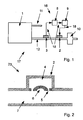
- Fig. 1 shows a schematic view of a possible basic structure of a counter sound system 16 for an automotive air conditioning system which is not part of the invention.
- the refrigerant circuit 17 of the motor vehicle air conditioning system is only partially shown for reasons of clarity.
- the refrigerant compressor 1 is supplied with refrigerant via a suction pipe 11 which is at a relatively low pressure level.
- the refrigerant may be the common R134a, R744, or other alternative refrigerants.
- the pressure of the refrigerant is increased to the pressure prevailing on the high-pressure side 12 of the refrigerant circuit 17, and discharged via the high-pressure line 12.
- a pressure probe 3 is arranged on the high-pressure line 12.
- the pressure probe 3 is designed as a dynamic pressure probe 3, that is, it can register pressure variations with a high time resolution. On the other hand, the pressure probe 3 does not need to register a "DC voltage component" of the fluid pressure.
- the measured values 19 recorded by the pressure probe 3 are transmitted via a cable 18 to an electronic controller 8.
- the electronic controller 8 may be a single-board computer.
- the measured values 19 (comparatively corresponding to the dynamic components in. Fig. 4 ) are offset by the electronic controller 8 using an algorithm stored in the electronic controller 8.
- an output signal is output from the electronic controller 8, which is sent via a further cable 18 to an amplifier 9.
- the amplifier 9 amplifies the signal accordingly and forwards it to the sound generator 2, which is located on the high-pressure line 12 of the refrigerant circuit 17.
- the algorithm in the electronic controller 8 is chosen so that the sound generator 2 generates an in-phase pulsation in the refrigerant and is greatly reduced as a result of the total level 20 of the pressure pulsations in the refrigerant. In this way, the registered in the vehicle cabin compressor noise is ultimately significantly reduced.
- the effect of the antinoise system 16 can be problemally limited to lower frequencies. Since the lowest pressure pulsations generated by the Käfteschkompressor 1 depending on the speed, translation and number of cylinders usually in the range of about 70 Hz, 100 Hz, 120 Hz or 150 Hz, is sufficient in practical applications in the field of automotive air conditioning often a cutoff frequency of the antinoise system 16 of about 1 , 5 kHz off.
- the sound generator 2 has a housing 23 which is attached directly to the high-pressure line 12.
- the housing 23 of the sounder 2 forms a background volume 4.
- a piezoelectric bending oscillator 6 is arranged between the background volume 4 of the housing 23 and the inner volume 7 of the high-pressure line 12.
- the deflection of the bending oscillator 6 can be changed by an electrical pulse calculated by the electronic controller 8 and amplified by the amplifier 9.
- the inner volume 7 of the high pressure line 12 can be actively varied, and thereby the pressure pulsations of the refrigerant can be damped.
- Fig. 2 It can also be seen that pressure compensation connections 5 are provided between background volume 4 and interior volume 7 of high-pressure line 12. Through this refrigerant can flow through, so that on both sides 4, 7 of the bending oscillator 6 of the same time-averaged pressure ("DC component") is applied.
- DC component time-averaged pressure
- the sounder 2 as in Fig. 1 arranged directly behind the compressor 1 so the refrigerant is in gaseous or supercritical form (depending on which refrigerant is used) before.
- the sound generator 2 is operated in a part of the refrigerant circuit 17 in which the refrigerant is (predominantly) in liquid form, then the refrigerant located in the background volume 4 can be brought into the gaseous state by heating.
- an electric heater, a use of exhaust gases of an internal combustion engine or a surface enlarging device eg a so-called heat sink
- the in Fig. 2 shown construction of a sounder 2 can be used in an analogous manner for a Druckpulsationssensor 3.
- the bending oscillator 6 is to be designed accordingly.
- Fig. 3 is shown an inventive "irreversible" volume control in a closed refrigerant circuit.
- two valves (14a, 14b) connected in series are arranged between the high pressure line 12 coming from the compressor 1 and the suction line 11 leading to the compressor 1, two valves (14a, 14b) connected in series (related to the fluid path) are arranged.
- a buffer volume 13 is provided between the two electrically controllable valves 14a, 14b.
- the electrically controllable valves 14a, 14b are controlled by an electronic controller 15 so that they act in conjunction with the buffer volume 13 as an active damping device.
- the electrically controllable valve 14a opens on the high pressure passage 12 side to discharge refrigerant into the buffer volume 13.
- the dynamic pressure in the high pressure line 12 is lowered.
- the conditions are reversed accordingly.
- the pressure in the buffer volume 13 will usually be between the high pressure in the high pressure line 12 and the low pressure in the suction line 11.
- one of the electrically controllable valves 14a, 14b can additionally be adjusted such that a constant mass flow is superimposed on the mass flow rate.
- a big advantage of in Fig. 3 illustrated inventive system is that both on the high pressure side 12, and on the low pressure side 11 a active noise control can be done. If only one side is actively attenuated, it is sufficient to operate the electrically controllable valve 14a, 14b in a constant mode on the respective opposite side in order to keep the pressure difference to the buffer volume 13 approximately constant.
- the electrically controllable valve operated in constant mode can be replaced by a throttle, or the mass flow can be discharged directly into a suitable line 11, 12.
- the related to Fig. 3 described training options according to the invention have the disadvantage that the average pressure on the high pressure side 12 is slightly lowered; conversely, the mean pressure on the low-pressure side 11 increases. As a result, it reduces the efficiency of the refrigerant circuit 17 somewhat. In order to lower the efficiency as little as possible, it is advantageous if the in Fig. 4 setpoint 21 is selected depending on the operating point and the driving condition of the motor vehicle. The setpoint 21 determines to which level the pressure on the high-pressure side 12 is downregulated or up-regulated on the low-pressure side 11.
- the best reduction on the high-pressure side 12 is usually achieved when the value of the setpoint 21 is less than or equal to the minimum value p min of the temporal pressure curve. Conversely, it is on the low pressure side 11th
- the time course is characterized by the compressor stroke frequency or any other caused by the compressor 1 noise frequency.
- the "DC component" of the pressure is due to the operating parameters the refrigerant circuit 17, also time-variable, albeit with a significantly different time constant than the compressor pressure pulses.
- both components must be determined separately in order to determine the setpoint 21 optimally in each operating state.
Landscapes
- Engineering & Computer Science (AREA)
- General Engineering & Computer Science (AREA)
- Mechanical Engineering (AREA)
- Physics & Mathematics (AREA)
- Thermal Sciences (AREA)
- Air-Conditioning For Vehicles (AREA)
- Pipe Accessories (AREA)
Claims (8)
- Dispositif (22) d'amortissement de pulsations de pression de fluides servant à l'amortissement de pulsations de pression dans des fluides comportant une proportion de liquide de 70 %, 75 %, 80 %, 85 %, 90 %, 93 %, 95 %, 96 %, 97 %, 98 %, 99 % ou plus et / ou de pulsations de pression dans des fluides ayant une pression de 5 bars, 10 bars, 15 bars, 20 bars, 25 bars, 30 bars, 35 bars, 40 bars, 50 bars, 60 bars ou supérieure, comprenant au moins un dispositif (14a, 14b) influençant le volume, dispositif par lequel peut être influencé le volume disponible pour le fluide, comprenant au moins un détecteur (3a, 3b) de pulsations de pression, où au moins un dispositif (14a, 14b) influençant le volume est activé (15) en fonction de la valeur de sortie d'au moins l'un des capteurs (3a, 3b) de pulsations de pression, caractérisé en ce qu'au moins un dispositif (14a, 14b) influençant le volume provoque une modification de volume irréversible.
- Dispositif (22) d'amortissement de pulsations de pression de fluide selon la revendication 1, caractérisé en ce que la modification de volume irréversible est un délestage de pression.
- Dispositif (22) d'amortissement de pulsations de pression de fluides selon la revendication 1 ou 2, caractérisé en ce que l'activation d'au moins un dispositif (14a, 14b) influençant le volume se produit au moyen d'un dispositif de commande électronique (15) qui active le dispositif (14a, 14b) - au moins au nombre de un - influençant le volume, à la façon d'une source sonore opposée.
- Dispositif d'amortissement de pulsations de pression de fluides selon l'une quelconque des revendications précédentes, caractérisé en ce que le dispositif (22) d'amortissement de pulsations de pression de fluides, en particulier au moins un capteur (3a, 3b) de pulsations de pression et / ou au moins un dispositif (14a, 14b) influençant le volume, sont disposés à proximité d'un dispositif (1) produisant des pulsations de pression, où de préférence au moins un capteur (3a, 3b) de pulsations de pression, vu dans la direction d'écoulement du fluide, est disposé en amont d'au moins un dispositif (14a, 14b) influençant le volume.
- Dispositif comportant au moins un circuit de fluide fermé (17), en particulier système de climatisation comprenant un circuit de fluide frigorigène, en particulier de préférence système de climatisation d'un véhicule automobile comprenant un circuit de fluide frigorigène, caractérisé par und dispositif (22) d'amortissement de pulsations de pression de fluides conformément à l'une quelconque des revendications 1 à 4.
- Dispositif comportant au moins un circuit de fluide ferme (17) selon la revendication 5, caractérisé en ce qu'au moins un dispositif (14a, 14b) influençant le volume est configuré comme une communication (13) fluidique variable, située entre une partie haute pression (12) et une partie basse pression (11) du circuit de fluide fermé (17).
- Dispositif comportant au moins un circuit de fluide fermé (17) selon la revendication 6, caractérisé en ce que la communication fluidique présente au moins deux soupapes réglables (14a, 14b) qui meuvent être activées indépendamment l'une de l'autre et entre desquelles est disposé un espace creux de compensation (13).
- Dispositif comportant au moins un circuit de fluide fermé (17) selon l'une quelconque des revendication 5 à 7, caractérisé en ce que le dispositif (14a, 14b) - au moins au nombre de un - influençant le volume est activé en fonction de l'état de fonctionnement du circuit de fluide fermé (17).
Applications Claiming Priority (1)
| Application Number | Priority Date | Filing Date | Title |
|---|---|---|---|
| DE102008019488A DE102008019488A1 (de) | 2008-04-17 | 2008-04-17 | Fluiddruckpulsationsdämpfungsvorrichtung |
Publications (2)
| Publication Number | Publication Date |
|---|---|
| EP2116752A1 EP2116752A1 (fr) | 2009-11-11 |
| EP2116752B1 true EP2116752B1 (fr) | 2012-03-14 |
Family
ID=40789861
Family Applications (1)
| Application Number | Title | Priority Date | Filing Date |
|---|---|---|---|
| EP09005386A Not-in-force EP2116752B1 (fr) | 2008-04-17 | 2009-04-15 | Dispositif d'amortissement de pulsations de pression de fluide |
Country Status (3)
| Country | Link |
|---|---|
| EP (1) | EP2116752B1 (fr) |
| AT (1) | ATE549569T1 (fr) |
| DE (1) | DE102008019488A1 (fr) |
Families Citing this family (14)
| Publication number | Priority date | Publication date | Assignee | Title |
|---|---|---|---|---|
| US8334768B2 (en) | 2009-12-22 | 2012-12-18 | Mindray Ds Usa, Inc. | Systems and methods for determining a location of a medical device |
| WO2011144543A1 (fr) * | 2010-05-17 | 2011-11-24 | Mindray Medical Sweden Ab | Actionneur pneumatique transitoire, et procédé d'actionnement transitoire |
| GB201108917D0 (en) | 2011-05-27 | 2011-07-13 | Rolls Royce Plc | A Hydraulic damping apparatus |
| EP2677220A1 (fr) * | 2012-06-20 | 2013-12-25 | TI Automotive Engineering Centre (Heidelberg) GmbH | Tuyau pour le transport d'un réfrigérant d'un système de conditionnement d'air et système de tuyau |
| CN104235987B (zh) * | 2014-09-30 | 2017-02-15 | 长城汽车股份有限公司 | 空调系统及具有其的车辆 |
| GB201509228D0 (en) * | 2015-05-29 | 2015-07-15 | Norgren Ltd C A | Active cancellation of a pulsating flow with a flow signal noise reference |
| CN104879602B (zh) * | 2015-06-04 | 2018-05-01 | 青岛大学 | 一种管道自动消音装置 |
| JP2018523108A (ja) * | 2015-06-12 | 2018-08-16 | プロフタガレン アクチエボラグProvtagaren Ab | 流量測定のためのパルス消去 |
| GB201511982D0 (en) * | 2015-07-08 | 2015-08-19 | Norgren Ltd C A | Active cancellation of a pulsating flow with a source noise reference |
| DE102017001317B3 (de) | 2017-03-18 | 2018-03-08 | Thomas Magnete Gmbh | Hubkolbenpumpe mit aktivem Dämpfer und Verfahren zum Betrieb der Hubkolbenpumpe |
| DE102019202077A1 (de) * | 2019-02-15 | 2020-08-20 | Robert Bosch Gmbh | Wärmepumpe |
| DE102020200118A1 (de) * | 2020-01-08 | 2021-07-08 | Volkswagen Aktiengesellschaft | Verfahren zur Detektion eines kritischen Zustands bei einem Kältemittelkreislauf eines Fahrzeuges |
| CN111981236A (zh) * | 2020-07-14 | 2020-11-24 | 江苏科技大学 | 一种主动调频和改变阻带的消声装置及其消声方法 |
| CN116085572A (zh) * | 2021-01-14 | 2023-05-09 | 哈尔滨工程大学 | 一种基于电声耦合的管道低频噪声控制装置 |
Family Cites Families (15)
| Publication number | Priority date | Publication date | Assignee | Title |
|---|---|---|---|---|
| IT1211848B (it) | 1987-10-12 | 1989-11-03 | Roma A | Dispositivo silenziatore per scarichi di motori e simili,ad interferenza acustica |
| DE4302977A1 (de) * | 1993-02-03 | 1994-03-31 | Bosch Gmbh Robert | Hydraulikanlage |
| DE4441217C2 (de) * | 1993-12-17 | 1998-09-10 | Voith Sulzer Papiermasch Gmbh | Verfahren zur Dämpfung von Druckstößen sowie Vorrichtung zur Durchführung des Verfahrens |
| US5492451A (en) * | 1994-10-03 | 1996-02-20 | Caterpillar Inc. | Apparatus and method for attenuation of fluid-borne noise |
| US6009180A (en) | 1996-09-17 | 1999-12-28 | The Boeing Company | Fluidic element noise and vibration control constructs and methods |
| AU8060498A (en) * | 1997-06-06 | 1998-12-21 | Echlin Inc. | Suppression of fluid-borne noise |
| DE19822148C2 (de) | 1997-06-19 | 2000-08-17 | Dornier Gmbh | Verfahren und Vorrichtung zur Lärmminderung schallführender Medien in Rohrleitungen |
| US6658118B1 (en) * | 1998-06-05 | 2003-12-02 | Dana Corporation | Suppression of fluid-borne noise |
| DE19832517C2 (de) | 1998-07-20 | 2003-03-20 | Ibs Ingenieurbuero Fuer Schall | Verfahren zur aktiven Schalldämpfung und Schalldämpfer dafür |
| US6234758B1 (en) * | 1999-12-01 | 2001-05-22 | Caterpillar Inc. | Hydraulic noise reduction assembly with variable side branch |
| US6854269B2 (en) * | 2002-07-23 | 2005-02-15 | Caterpillar Inc. | Noise attenuation in a hydraulic circuit |
| DE10316946A1 (de) * | 2003-04-12 | 2004-10-21 | Daimlerchrysler Ag | Vorrichtung und Verfahren zur Dämpfung von Druckschwingungen in Hydraulikleitungen |
| DE10322570B4 (de) | 2003-05-20 | 2013-04-11 | Mahle Filtersysteme Gmbh | Schalldämpfungsvorrichtung bei einem Kraftfahrzeug |
| DE102005057399B4 (de) | 2005-11-30 | 2015-12-24 | Siemens Aktiengesellschaft | Gasströmungserzeuger mit einem Gasauslass und mit einem Stör-schallreduzierer und Verfahren |
| DE102005058547B4 (de) * | 2005-12-08 | 2012-04-12 | Airbus Operations Gmbh | Einrichtung zur Verminderung von Hydrofluidschwingungen in einem Hydrauliksystem |
-
2008
- 2008-04-17 DE DE102008019488A patent/DE102008019488A1/de not_active Withdrawn
-
2009
- 2009-04-15 AT AT09005386T patent/ATE549569T1/de active
- 2009-04-15 EP EP09005386A patent/EP2116752B1/fr not_active Not-in-force
Also Published As
| Publication number | Publication date |
|---|---|
| ATE549569T1 (de) | 2012-03-15 |
| EP2116752A1 (fr) | 2009-11-11 |
| DE102008019488A1 (de) | 2009-10-22 |
Similar Documents
| Publication | Publication Date | Title |
|---|---|---|
| EP2116752A1 (fr) | Dispositif d'amortissement de pulsations de pression de fluide | |
| DE102011084567C5 (de) | Aktiver Schalldämpfer | |
| EP2912310A1 (fr) | Pompe à membrane à piston | |
| DE69807736T2 (de) | Vorrichtung und verfahren für schalldämpfungseinheiten | |
| EP0679832A1 (fr) | Dispositif de réduction de pulsations de pression dans conduits hydrauliques | |
| WO2013091932A1 (fr) | Amortisseur de pulsations de pression pour un système de freinage de véhicule | |
| EP0971164A2 (fr) | Dispositif de réduction de pulsations de pression dans des conduits hydrauliques | |
| EP1507682B1 (fr) | Dispositif de configuration sonore pour un vehicule automobile | |
| WO2019037840A1 (fr) | Procédé d'amortissement des pulsations dans un équipement conduisant un fluide | |
| EP3145767A1 (fr) | Système de freinage de véhicule à régulation antipatinage | |
| DE102015011175A1 (de) | Abgasanlage für eine Brennkraftmaschine | |
| DE102016206440A1 (de) | Verfahren zur Pulsationsdämpfung in einer ein Fluid führenden Anlage | |
| EP2708745B1 (fr) | Compresseur à pistons à plusieurs étages doté de soupapes de ralenti pour la réalisation d'une fonction de ralenti | |
| DE102007057567B4 (de) | Pneumatische Niveauregeleinrichtung für Fahrzeuge | |
| EP1948927B1 (fr) | Compresseur de climatisation a systeme de limitation de la pression differentielle | |
| DE102005036921A1 (de) | Pulsationsminderer für hydraulische Systeme | |
| DE102022000104A1 (de) | Vorrichtung zur Unterdrückung und Modulation von Druckpulsationen in gasführenden Rohrleitungen | |
| DE102013004786A1 (de) | Kompressionswärmepumpe oder Kompressionskältemaschine sowie Verfahren zur Regelug derselben | |
| EP2616298A2 (fr) | Unité d'actionnement de frein pour un système de freinage de véhicule automobile et groupe pompe-moteur pour produire une dépression pour une unité d'actionnement de frein d'un système de freinage de véhicule automobile | |
| DE102008015016B3 (de) | Schalldämpferanordnung für eine Abgasanlage eines Kraftfahrzeuges | |
| DE102008023553A1 (de) | Schalldämpfer für eine Abgasanlage | |
| DE102007062619B3 (de) | Luftfederdämpfer | |
| DE102005057399B4 (de) | Gasströmungserzeuger mit einem Gasauslass und mit einem Stör-schallreduzierer und Verfahren | |
| DE102020209681A1 (de) | Vorrichtung und Verfahren zur aktiven Reduktion von Druckfluktuationen in einem hydrodynamischen System | |
| EP4426942B1 (fr) | Dispositif de protection pour un accès à une chaudière |
Legal Events
| Date | Code | Title | Description |
|---|---|---|---|
| PUAI | Public reference made under article 153(3) epc to a published international application that has entered the european phase |
Free format text: ORIGINAL CODE: 0009012 |
|
| AK | Designated contracting states |
Kind code of ref document: A1 Designated state(s): AT BE BG CH CY CZ DE DK EE ES FI FR GB GR HR HU IE IS IT LI LT LU LV MC MK MT NL NO PL PT RO SE SI SK TR |
|
| 17P | Request for examination filed |
Effective date: 20100511 |
|
| 17Q | First examination report despatched |
Effective date: 20100609 |
|
| RIC1 | Information provided on ipc code assigned before grant |
Ipc: F16L 55/04 20060101AFI20110818BHEP Ipc: F16L 55/033 20060101ALI20110818BHEP Ipc: B60H 1/00 20060101ALI20110818BHEP Ipc: B60H 1/32 20060101ALI20110818BHEP |
|
| GRAP | Despatch of communication of intention to grant a patent |
Free format text: ORIGINAL CODE: EPIDOSNIGR1 |
|
| GRAS | Grant fee paid |
Free format text: ORIGINAL CODE: EPIDOSNIGR3 |
|
| GRAA | (expected) grant |
Free format text: ORIGINAL CODE: 0009210 |
|
| AK | Designated contracting states |
Kind code of ref document: B1 Designated state(s): AT BE BG CH CY CZ DE DK EE ES FI FR GB GR HR HU IE IS IT LI LT LU LV MC MK MT NL NO PL PT RO SE SI SK TR |
|
| REG | Reference to a national code |
Ref country code: GB Ref legal event code: FG4D Free format text: NOT ENGLISH |
|
| REG | Reference to a national code |
Ref country code: AT Ref legal event code: REF Ref document number: 549569 Country of ref document: AT Kind code of ref document: T Effective date: 20120315 Ref country code: CH Ref legal event code: EP |
|
| REG | Reference to a national code |
Ref country code: IE Ref legal event code: FG4D Free format text: LANGUAGE OF EP DOCUMENT: GERMAN |
|
| REG | Reference to a national code |
Ref country code: DE Ref legal event code: R096 Ref document number: 502009002998 Country of ref document: DE Effective date: 20120510 |
|
| REG | Reference to a national code |
Ref country code: NL Ref legal event code: VDEP Effective date: 20120314 |
|
| PG25 | Lapsed in a contracting state [announced via postgrant information from national office to epo] |
Ref country code: LT Free format text: LAPSE BECAUSE OF FAILURE TO SUBMIT A TRANSLATION OF THE DESCRIPTION OR TO PAY THE FEE WITHIN THE PRESCRIBED TIME-LIMIT Effective date: 20120314 Ref country code: NO Free format text: LAPSE BECAUSE OF FAILURE TO SUBMIT A TRANSLATION OF THE DESCRIPTION OR TO PAY THE FEE WITHIN THE PRESCRIBED TIME-LIMIT Effective date: 20120614 Ref country code: HR Free format text: LAPSE BECAUSE OF FAILURE TO SUBMIT A TRANSLATION OF THE DESCRIPTION OR TO PAY THE FEE WITHIN THE PRESCRIBED TIME-LIMIT Effective date: 20120314 |
|
| LTIE | Lt: invalidation of european patent or patent extension |
Effective date: 20120314 |
|
| PG25 | Lapsed in a contracting state [announced via postgrant information from national office to epo] |
Ref country code: LV Free format text: LAPSE BECAUSE OF FAILURE TO SUBMIT A TRANSLATION OF THE DESCRIPTION OR TO PAY THE FEE WITHIN THE PRESCRIBED TIME-LIMIT Effective date: 20120314 Ref country code: FI Free format text: LAPSE BECAUSE OF FAILURE TO SUBMIT A TRANSLATION OF THE DESCRIPTION OR TO PAY THE FEE WITHIN THE PRESCRIBED TIME-LIMIT Effective date: 20120314 Ref country code: GR Free format text: LAPSE BECAUSE OF FAILURE TO SUBMIT A TRANSLATION OF THE DESCRIPTION OR TO PAY THE FEE WITHIN THE PRESCRIBED TIME-LIMIT Effective date: 20120615 |
|
| PG25 | Lapsed in a contracting state [announced via postgrant information from national office to epo] |
Ref country code: CY Free format text: LAPSE BECAUSE OF FAILURE TO SUBMIT A TRANSLATION OF THE DESCRIPTION OR TO PAY THE FEE WITHIN THE PRESCRIBED TIME-LIMIT Effective date: 20120314 |
|
| BERE | Be: lapsed |
Owner name: BEHR G.M.B.H. & CO. KG Effective date: 20120430 |
|
| PG25 | Lapsed in a contracting state [announced via postgrant information from national office to epo] |
Ref country code: PL Free format text: LAPSE BECAUSE OF FAILURE TO SUBMIT A TRANSLATION OF THE DESCRIPTION OR TO PAY THE FEE WITHIN THE PRESCRIBED TIME-LIMIT Effective date: 20120314 Ref country code: CZ Free format text: LAPSE BECAUSE OF FAILURE TO SUBMIT A TRANSLATION OF THE DESCRIPTION OR TO PAY THE FEE WITHIN THE PRESCRIBED TIME-LIMIT Effective date: 20120314 Ref country code: EE Free format text: LAPSE BECAUSE OF FAILURE TO SUBMIT A TRANSLATION OF THE DESCRIPTION OR TO PAY THE FEE WITHIN THE PRESCRIBED TIME-LIMIT Effective date: 20120314 Ref country code: SE Free format text: LAPSE BECAUSE OF FAILURE TO SUBMIT A TRANSLATION OF THE DESCRIPTION OR TO PAY THE FEE WITHIN THE PRESCRIBED TIME-LIMIT Effective date: 20120314 Ref country code: SI Free format text: LAPSE BECAUSE OF FAILURE TO SUBMIT A TRANSLATION OF THE DESCRIPTION OR TO PAY THE FEE WITHIN THE PRESCRIBED TIME-LIMIT Effective date: 20120314 Ref country code: IS Free format text: LAPSE BECAUSE OF FAILURE TO SUBMIT A TRANSLATION OF THE DESCRIPTION OR TO PAY THE FEE WITHIN THE PRESCRIBED TIME-LIMIT Effective date: 20120714 Ref country code: RO Free format text: LAPSE BECAUSE OF FAILURE TO SUBMIT A TRANSLATION OF THE DESCRIPTION OR TO PAY THE FEE WITHIN THE PRESCRIBED TIME-LIMIT Effective date: 20120314 |
|
| PG25 | Lapsed in a contracting state [announced via postgrant information from national office to epo] |
Ref country code: SK Free format text: LAPSE BECAUSE OF FAILURE TO SUBMIT A TRANSLATION OF THE DESCRIPTION OR TO PAY THE FEE WITHIN THE PRESCRIBED TIME-LIMIT Effective date: 20120314 Ref country code: PT Free format text: LAPSE BECAUSE OF FAILURE TO SUBMIT A TRANSLATION OF THE DESCRIPTION OR TO PAY THE FEE WITHIN THE PRESCRIBED TIME-LIMIT Effective date: 20120716 Ref country code: MC Free format text: LAPSE BECAUSE OF NON-PAYMENT OF DUE FEES Effective date: 20120430 |
|
| PGFP | Annual fee paid to national office [announced via postgrant information from national office to epo] |
Ref country code: FR Payment date: 20120716 Year of fee payment: 4 |
|
| REG | Reference to a national code |
Ref country code: IE Ref legal event code: MM4A |
|
| PLBE | No opposition filed within time limit |
Free format text: ORIGINAL CODE: 0009261 |
|
| STAA | Information on the status of an ep patent application or granted ep patent |
Free format text: STATUS: NO OPPOSITION FILED WITHIN TIME LIMIT |
|
| PG25 | Lapsed in a contracting state [announced via postgrant information from national office to epo] |
Ref country code: BE Free format text: LAPSE BECAUSE OF NON-PAYMENT OF DUE FEES Effective date: 20120430 Ref country code: DK Free format text: LAPSE BECAUSE OF FAILURE TO SUBMIT A TRANSLATION OF THE DESCRIPTION OR TO PAY THE FEE WITHIN THE PRESCRIBED TIME-LIMIT Effective date: 20120314 Ref country code: NL Free format text: LAPSE BECAUSE OF FAILURE TO SUBMIT A TRANSLATION OF THE DESCRIPTION OR TO PAY THE FEE WITHIN THE PRESCRIBED TIME-LIMIT Effective date: 20120314 Ref country code: IE Free format text: LAPSE BECAUSE OF NON-PAYMENT OF DUE FEES Effective date: 20120415 |
|
| 26N | No opposition filed |
Effective date: 20121217 |
|
| PG25 | Lapsed in a contracting state [announced via postgrant information from national office to epo] |
Ref country code: MK Free format text: LAPSE BECAUSE OF FAILURE TO SUBMIT A TRANSLATION OF THE DESCRIPTION OR TO PAY THE FEE WITHIN THE PRESCRIBED TIME-LIMIT Effective date: 20120314 Ref country code: IT Free format text: LAPSE BECAUSE OF FAILURE TO SUBMIT A TRANSLATION OF THE DESCRIPTION OR TO PAY THE FEE WITHIN THE PRESCRIBED TIME-LIMIT Effective date: 20120314 |
|
| REG | Reference to a national code |
Ref country code: DE Ref legal event code: R097 Ref document number: 502009002998 Country of ref document: DE Effective date: 20121217 |
|
| PG25 | Lapsed in a contracting state [announced via postgrant information from national office to epo] |
Ref country code: ES Free format text: LAPSE BECAUSE OF FAILURE TO SUBMIT A TRANSLATION OF THE DESCRIPTION OR TO PAY THE FEE WITHIN THE PRESCRIBED TIME-LIMIT Effective date: 20120625 |
|
| PG25 | Lapsed in a contracting state [announced via postgrant information from national office to epo] |
Ref country code: BG Free format text: LAPSE BECAUSE OF FAILURE TO SUBMIT A TRANSLATION OF THE DESCRIPTION OR TO PAY THE FEE WITHIN THE PRESCRIBED TIME-LIMIT Effective date: 20120614 Ref country code: MT Free format text: LAPSE BECAUSE OF FAILURE TO SUBMIT A TRANSLATION OF THE DESCRIPTION OR TO PAY THE FEE WITHIN THE PRESCRIBED TIME-LIMIT Effective date: 20120314 |
|
| REG | Reference to a national code |
Ref country code: CH Ref legal event code: PL |
|
| GBPC | Gb: european patent ceased through non-payment of renewal fee |
Effective date: 20130415 |
|
| PG25 | Lapsed in a contracting state [announced via postgrant information from national office to epo] |
Ref country code: LI Free format text: LAPSE BECAUSE OF NON-PAYMENT OF DUE FEES Effective date: 20130430 Ref country code: CH Free format text: LAPSE BECAUSE OF NON-PAYMENT OF DUE FEES Effective date: 20130430 Ref country code: GB Free format text: LAPSE BECAUSE OF NON-PAYMENT OF DUE FEES Effective date: 20130415 |
|
| REG | Reference to a national code |
Ref country code: FR Ref legal event code: ST Effective date: 20131231 |
|
| PG25 | Lapsed in a contracting state [announced via postgrant information from national office to epo] |
Ref country code: FR Free format text: LAPSE BECAUSE OF NON-PAYMENT OF DUE FEES Effective date: 20130430 |
|
| PG25 | Lapsed in a contracting state [announced via postgrant information from national office to epo] |
Ref country code: TR Free format text: LAPSE BECAUSE OF FAILURE TO SUBMIT A TRANSLATION OF THE DESCRIPTION OR TO PAY THE FEE WITHIN THE PRESCRIBED TIME-LIMIT Effective date: 20120314 |
|
| PG25 | Lapsed in a contracting state [announced via postgrant information from national office to epo] |
Ref country code: LU Free format text: LAPSE BECAUSE OF NON-PAYMENT OF DUE FEES Effective date: 20120415 |
|
| PG25 | Lapsed in a contracting state [announced via postgrant information from national office to epo] |
Ref country code: HU Free format text: LAPSE BECAUSE OF FAILURE TO SUBMIT A TRANSLATION OF THE DESCRIPTION OR TO PAY THE FEE WITHIN THE PRESCRIBED TIME-LIMIT Effective date: 20090415 |
|
| REG | Reference to a national code |
Ref country code: DE Ref legal event code: R082 Ref document number: 502009002998 Country of ref document: DE Representative=s name: GRAUEL, ANDREAS, DIPL.-PHYS. DR. RER. NAT., DE |
|
| REG | Reference to a national code |
Ref country code: DE Ref legal event code: R081 Ref document number: 502009002998 Country of ref document: DE Owner name: MAHLE INTERNATIONAL GMBH, DE Free format text: FORMER OWNER: BEHR GMBH & CO. KG, 70469 STUTTGART, DE Effective date: 20150319 Ref country code: DE Ref legal event code: R082 Ref document number: 502009002998 Country of ref document: DE Representative=s name: GRAUEL, ANDREAS, DIPL.-PHYS. DR. RER. NAT., DE Effective date: 20150319 |
|
| REG | Reference to a national code |
Ref country code: AT Ref legal event code: MM01 Ref document number: 549569 Country of ref document: AT Kind code of ref document: T Effective date: 20140415 |
|
| PG25 | Lapsed in a contracting state [announced via postgrant information from national office to epo] |
Ref country code: AT Free format text: LAPSE BECAUSE OF NON-PAYMENT OF DUE FEES Effective date: 20140415 |
|
| PGFP | Annual fee paid to national office [announced via postgrant information from national office to epo] |
Ref country code: DE Payment date: 20180502 Year of fee payment: 10 |
|
| REG | Reference to a national code |
Ref country code: DE Ref legal event code: R119 Ref document number: 502009002998 Country of ref document: DE |
|
| PG25 | Lapsed in a contracting state [announced via postgrant information from national office to epo] |
Ref country code: DE Free format text: LAPSE BECAUSE OF NON-PAYMENT OF DUE FEES Effective date: 20191101 |