EP2115240B1 - Verbesserter latten/balken-träger - Google Patents
Verbesserter latten/balken-träger Download PDFInfo
- Publication number
- EP2115240B1 EP2115240B1 EP08706091.9A EP08706091A EP2115240B1 EP 2115240 B1 EP2115240 B1 EP 2115240B1 EP 08706091 A EP08706091 A EP 08706091A EP 2115240 B1 EP2115240 B1 EP 2115240B1
- Authority
- EP
- European Patent Office
- Prior art keywords
- support means
- walls
- joist
- batten
- support
- Prior art date
- Legal status (The legal status is an assumption and is not a legal conclusion. Google has not performed a legal analysis and makes no representation as to the accuracy of the status listed.)
- Revoked
Links
- NJPPVKZQTLUDBO-UHFFFAOYSA-N novaluron Chemical compound C1=C(Cl)C(OC(F)(F)C(OC(F)(F)F)F)=CC=C1NC(=O)NC(=O)C1=C(F)C=CC=C1F NJPPVKZQTLUDBO-UHFFFAOYSA-N 0.000 claims description 27
- 238000000034 method Methods 0.000 claims description 5
- 230000007423 decrease Effects 0.000 claims description 3
- 239000000463 material Substances 0.000 description 3
- 239000002023 wood Substances 0.000 description 2
- 239000004606 Fillers/Extenders Substances 0.000 description 1
- 239000002131 composite material Substances 0.000 description 1
- 230000008602 contraction Effects 0.000 description 1
- 230000008878 coupling Effects 0.000 description 1
- 238000010168 coupling process Methods 0.000 description 1
- 238000005859 coupling reaction Methods 0.000 description 1
- 238000007373 indentation Methods 0.000 description 1
- 238000012986 modification Methods 0.000 description 1
- 230000004048 modification Effects 0.000 description 1
- 239000004033 plastic Substances 0.000 description 1
- 229920003023 plastic Polymers 0.000 description 1
- 238000010079 rubber tapping Methods 0.000 description 1
- XLYOFNOQVPJJNP-UHFFFAOYSA-N water Substances O XLYOFNOQVPJJNP-UHFFFAOYSA-N 0.000 description 1
Images


Classifications
-
- E—FIXED CONSTRUCTIONS
- E04—BUILDING
- E04D—ROOF COVERINGS; SKY-LIGHTS; GUTTERS; ROOF-WORKING TOOLS
- E04D12/00—Non-structural supports for roofing materials, e.g. battens, boards
- E04D12/004—Battens
- E04D12/006—Batten-supporting means
-
- E—FIXED CONSTRUCTIONS
- E04—BUILDING
- E04F—FINISHING WORK ON BUILDINGS, e.g. STAIRS, FLOORS
- E04F15/00—Flooring
- E04F15/02—Flooring or floor layers composed of a number of similar elements
- E04F15/024—Sectional false floors, e.g. computer floors
- E04F15/02447—Supporting structures
- E04F15/02464—Height adjustable elements for supporting the panels or a panel-supporting framework
- E04F15/0247—Screw jacks
- E04F15/02482—Screw jacks with a variable angle between panel and support
Definitions
- This invention relates to an improved batten/joist support, particularly, but not exclusively, for raised floors.
- a sub-floor comprising boards assembled on a framework comprising joists or battens, with the boards connected to the joists by means of coupling members.
- the sub-floors will be concrete.
- the boards are often made from wood or wood based composite materials, although other materials may be used.
- the joists are often mounted on height and slope adjustable pedestal supports, (also known as pedestal jacks) particularly where the sub-floor is sloping, to ensure that the raised floor is substantially horizontal.
- adjustable pedestal jack is shown in international patent application No PCT/AU2006/001613 .
- a mounting component is typically provided for mounting the joist the top of such pedestal support.
- That mounting typically comprises a plate defining two opposed upstanding walls which are spaced apart at a distance equal to the expected width of the joist.
- the joist is typically secured to the mounting by nails extending through apertures in the walls into the joist.
- the first problem is that the mounting is sized to suit the width of the joist. Therefore if the joist is oversized in width, the joist will not fit securely between the two walls of the mounting.
- the joists tend to be quite long and are supported by numerous pedestals each carrying their own support.
- the supports have to be correctly aligned in order to receive the joist, and it is very time consuming to align the supports sufficiently to fit the joists.
- US 2005/0055295 discloses a pedestal support in which there is a generally U-shaped member defining a flat base an two parallel sides/walls which define a gap which receives a loading beam.
- the beam support is rotatable to align with the beam.
- the beam support must be sized to suit the loading beam.
- US 2005/0055925 A1 describes a support means according to the preamble of claim 1. Any discussion of documents, acts, materials, devices, articles or the like which has been included in the present specification is solely for the purpose of providing a context for the present invention.
- a device for engaging the sides of a joist batten or other member having a, typically constant, predetermined width including a rotatable plate defining two spaced apart upstanding walls wherein the device may be positioned with the member located between the walls in one relative orientation where the walls do not touch the sides of the member and wherein rotation of the device relative to the member, causes the walls to abut the sides of the member.
- a support means for engaging a batten, joist or the like including a rotatable plate, and further defining means for engaging the support means with a support structure such as a pedestal jack or the like, in a manner which allows the support means to be rotated about an axis
- the support means further including two opposed upstanding walls defining a gap therebetween for receiving the batten, joist or the like, the walls being disposed either side of the axis and extending from a centremost position closest to the axis to a distal end farthest from the axis, characterised in that the walls are at least partly convex defining a convex portion, and in that the gap between the walls measured in a direction perpendicular to tangents to the walls decreases from the centremost part of the wall to the distal end of the wall, so that for a joist batten or the like having a predetermined width and positioned between the walls, rotation of the support means
- the convex portion may be curved. Alternatively, it may comprise a series of flats arranged to define a stepped curve.
- the radius of the convex portion may be greatest at the distal end of the convex portion and least at the centremost portion.
- the radius may change continuously, or in a discontinuous stepped fashion.
- the convex portions may include through apertures to receive fasteners such as nails, screws or the like.
- each wall includes a straight portion which extends from the centremost portion of the convex portion in an opposite direction to the convex portion, the straight portions of each wall being parallel to each other.
- the plate is generally circular.
- the support means may define a plurality of legs for engaging the support means in the top of the support such as a pedestal jack.
- the present invention also provides a raised floor comprising:
- the present invention also provides a method of providing a raised floor according to claim 13.
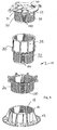
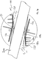
- Figure 1 shows a height adjustable pedestal 10 incorporating slope adjustment comprising a number of components.
- the height adjustable pedestal comprises a base element 12, having a circular planar base plate 14 defining a plane on which the pedestal stands in use, and an annular cylindrical portion 16 extending upwards from the base.
- the annular portion 16 is internally (female) threaded defining six internal threads 18.
- Spaced above the base 12 is a connector 20 which has an annular cross section and is internally and externally (male) threaded. The externally threaded portion locates in the base 16.
- an extender 30 which has a generally annular cross section comprising a lower portion 32 which is externally threaded and configured to locate inside the connecter 20 and an upper, larger diameter portion 34 which is internally threaded.
- a head portion 50 includes an upper portion 52 and a depending externally threaded cylindrical portion 54.
- a slope compensator plate 60 locates on top of the upper portion of the head portion 50.
- An aperture 70 having a circular cross-section and a depending circular wall is defined in the centre of the slope compensator plate 60.
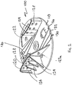
- the joist/batten support or support means 100 includes a generally circular plate 110.
- the batten support is typically moulded in a plastics material.
- four legs 112 depend from the underside of the centre 111 of the plate.
- Short, radially extending Protrusions 114 are defined at the foot of each leg.
- the legs are disposed around the perimeter of a circle of the same size as the aperture 70 into which they may be snap fitted, by inserting the legs into the aperture 70, with the protrusion being initially deflected inwards by the walls of the aperture then deflecting outwards and engaging the underneath of the wall of the aperture to lock the batten support to the top of the pedestal jack.
- two opposed upright walls 120, 122 are disposed either side of the centre 111 of the plate.
- Each wall is supported in an upright position by four buttresses 124.
- Each wall includes a generally straight portion 126 of gradually increasing height and a curved portion 128 of constant height which also defines a number of holes 129.
- the holes may receive fasteners such as screws, nails or the like.
- the holes are elongate in a horizontal direction to accommodate expansion and contraction of the joist supported by the batten.
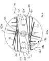
- the curved portions are generally convex when viewed from the centre 111 and diverge away from the centre. They are disposed on opposite sides of a notional line D passing through the centre 111 of the plate.
- the lines are curved such that they diverge away from a notional continuation C of the straight lines 126 shown in dashed lines.
- the convex/curved portion comprises three sections 128a, 128b, 128c interposed between the buttresses 124, with the distal portion 128a having a radius of about 220mm, the middle portion 152mm and the innermost portion which is closest to the centre of the plate having a radius of 140mm. Those dimensions could be varied. It would also be possible to have a curved portion with a constant radius.
- the convex portion could comprise a series of stepped flats or straight portions rather than a curved wall.
- the batten support is rotationally symmetrical through 180° about the centre of the plate.
- FIG. 4 Also shown in Figure 4 , are a series of pairs of spaced apart parallel straight lines 130, 132, 134 formed as shallow indentations in the surface of the plate located between the opposed walls and either side of the centre of the plate are two, generally square through apertures 136.
- the apertures allow the installer to see the top of the slope compensator plate of the pedestal jack to check that the jack is oriented correctly.
- the perpendicular distance between the lines 130 is greater than that between lines 132 which is in turn greater than that between lines 134.
- the holes allow the support to be secured to the compensator plate/head portion of the pedestal 10 using self tapping screws or the like.
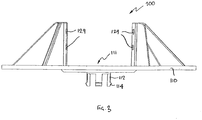
- the batten support is located on the top of a pedestal jack such as is shown in Figure 1 .
- the support may be rotated about its centre 111 on the jack.
- the plate may initially be rotated so that the joist 200 it is to be engaged with is aligned generally in the direction of the straight portions walls 126, as sis shown in Figure 6 .
- the perpendicular distance between tangents to the walls 120, 122 is greatest so there is the maximum amount of space to receive the joist/batten 200.
- the support 100 is rotated in a clockwise direction about its centre so that the longitudinal edges of the joists move towards lines 130, 132 and 134.
- Those lines are guide positions for joists of typical thicknesses, 130 being for the widest joists, 134 for the narrowest.
- the width of the joist will be somewhere between the perpendicular distance between the lines 134 and the perpendicular distance between the lines 132.
- the batten can be secured to the joist by hammering nails into the joist through the apertures 129 in the walls.
- the support 100 is secured to the pedestal using screws passing through the holes 127a and 127b.
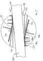
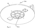
- Figures 8 and 9 show a variant 300 of the batten support 100 of Figures 2 to 7 .
- the support 300 has an alternative design of depending spigot 302 for engagement with the slope compensator plate of the pedestal jack, instead of the depending legs 112.
- the depending spigot 302 of support 300 is annular, having a circular cross-section in a plane parallel to the plate 110 of the support.
- a slope compensator 360 is a variant of that slope compensator 60 shown in Figure 1 , except that instead of having a through hole 70 for receiving the depending legs 112 of the support 100, it defining an annular channel 362 having a circular cross-section for receiving the depending spigot of the support 300.
- the channel is in the form of a blind bore having a base 364 so that any water which may pass into the channel cannot flow into the pedestal below.
- the channel 362 is substantially the same size, shape and depth as the depending spigot 302 so that the spigot is a tight fit within the channel.
Landscapes
- Engineering & Computer Science (AREA)
- Architecture (AREA)
- Civil Engineering (AREA)
- Structural Engineering (AREA)
- General Engineering & Computer Science (AREA)
- Floor Finish (AREA)
- Reinforcement Elements For Buildings (AREA)
Claims (15)
- Stützmittel (100; 300) zum Eingriff mit einer Leiste, einer Latte oder dergleichen (200), wobei die Stützmittel (100; 300) eine drehbare Platte (110) umfassen, und ferner Mittel (202; 302) definieren, um die Stützmittel (100; 300) mit einer Stützkonstruktion wie etwa einem höhenverstellbaren Träger oder dergleichen (10) in Eingriff zu bringen, in einer Weise, welche eine Drehung der Stützmittel (100, 300) um eine Achse erlaubt, wobei die Stützmittel (100, 300) ferner zwei gegenüberliegende aufrechte Wände (120, 122) mit einem dazwischen angeordneten Zwischenraum zur Aufnahme der Leiste, der Latte oder dergleichen (200) umfassen, wobei die Wände (120, 122) auf beiden Seiten der Achse angebracht sind und sich von einer dem Mittelpunkt der Achse am nächsten liegenden Stelle zu einem am weitesten von der Achse entfernten distalen Ende erstrecken, dadurch gekennzeichnet, dass die Wände (120, 122) wenigstens teilweise konvex sind und einen konvexen Abschnitt (128) bilden, und dass der in einer senkrechten Richtung zu den Tangenten der Wände (120, 122) gemessene Zwischenraum zwischen den Wänden (120, 122) von dem Mittelpunkt der Wand (120, 122) am nächsten liegende Abschnitt zum distalen Ende der Wand abnimmt, sodass, wenn eine Latte, eine Leiste oder dergleichen (200) mit einer vorbestimmten Breite zwischen den Wänden (120, 122) positioniert ist, eine Rotation der Stützmittel (100; 300) um die Achse in einer Richtung dazu führt, dass die Wände (120, 122) dazu tendieren, mit den Kanten der Latte (200) aufeinanderzutreffen und in die entgegengesetzte Drehrichtung dazu führt, dass sie dazu tendieren, sich von den Kanten der Latte (200) entfernen.
- Stützmittel (100; 300) nach Anspruch 1, wobei der konvexe Abschnitt (128) gekrümmt ist.
- Stützmittel (100; 300) nach Anspruch 1, wobei der konvexe Abschnitt (128) eine Reihe von ebenen Flächen umfasst, welche so angeordnet sind, dass sie eine stufenförmige Kurve definieren.
- Stützmittel (100; 300) nach einem der Ansprüche 1 bis 2, wobei der Radius des konvexen Abschnitts (128) am distalen Ende des konvexen Abschnitts (128) am größten und am dem Mittelpunkt am nächsten liegenden Abschnitt am geringsten ist.
- Stützmittel (100; 300) nach Anspruch 4, wobei sich der Radius kontinuierlich ändert.
- Stützmittel (100; 300) nach Anspruch 3, wobei sich der Radius diskontinuierlich stufenweise ändert.
- Stützmittel (100; 300) nach einem der Ansprüche 1 bis 6, wobei die konvexen Abschnitte (128) Durchgangsöffnungen (129) umfassen, um Befestigungsmittel wie etwa Nägel, Schrauben und dergleichen aufzunehmen.
- Stützmittel (100; 300) nach einem der Ansprüche 1 bis 7, wobei jede Wand (120, 122) einen geraden Abschnitt (126) umfasst, der sich von dem Mittelpunkt am nächsten liegenden Abschnitt des konvexen Abschnitts (128) in einer entgegengesetzten Richtung des konvexen Abschnitts (128) erstreckt, wobei die geraden Abschnitte (126) jeder Wand (120, 122) parallel zueinander sind.
- Stützmittel (100; 300) nach einem der Ansprüche 1 bis 8, wobei die Platte (110) im Allgemeinen kreisförmig ist.
- Stützmittel (100) nach einem der Ansprüche 1 bis 9, wobei die Stützvorrichtung (100) eine Vielzahl von herabhängenden Schenkeln (112) definiert, um das Stützmittel (100) mit dem oberen Teil der Stützkonstruktion (10) in Eingriff zu bringen.
- Stützmittel (300) nach einem der Ansprüche 1 bis 9, wobei das Stützmittel (300) einen herabhängenden ringförmigen Zapfen (302) zum in-Eingriff-bringen mit einer entsprechend geformten Blindbohrung im oberen Teil der Stützkonstruktion (10) definiert.
- Doppelboden umfassend:eine Vielzahl von höhenverstellbaren Trägern und dergleichen (10),Stützmittel (100; 300) nach einem der Ansprüche 1 bis 11, die auf den höhenverstellbaren Trägern (10) angeordnet sind, sowiesowie Balken (200), die an den Stützmitteln (100; 300) angebracht sind und sich zwischen diesen erstrecken.
- Verfahren zum Bereitstellen eines Doppelbodens unter Verwendung
einer Vielzahl von Stützkonstruktionen (10);
einer Vielzahl von Latten, Leisten und dergleichen (200); sowie
einer Vielzahl von Stützmitteln (100; 300) zum in-Eingriff-bringen mit der Leiste, der Latte oder dergleichen (200), wobei
die Stützmittel (100; 300) eine drehbare Platte (110) umfassen, und ferner Mittel (202, 302) definieren zum Eingriff mit der Stützkonstruktion (112; 302), in einer Weise, welche eine Drehung der Stützmittel (100; 300) um eine Achse erlaubt, und die Stützmittel (100; 300) ferner zwei gegenüberliegende aufrechte Wände (120, 122) mit einem dazwischen angeordneten Zwischenraum zur Aufnahme der Leiste, der Latte oder dergleichen (200) umfassen, wobei die Wände (120, 122) auf beiden Seiten der Achse angebracht sind und sich von einer dem Mittelpunkt der Achse am nächsten liegenden Stelle zu einem am weitesten von der Achse entfernten distalen Ende erstrecken, wobei die Wände (120, 122) wenigstens teilweise konvex sind und einen konvexen Abschnitt (128) umfassen, und wobei das Verfahren die Schritte umfasst:Vorsehen einer Vielzahl von Stützkonstruktionen (10),Anbringen der Stützmittel (100; 300) auf der Oberseite der Stützkonstruktion (10), wobei die Stützmittel (100; 300) so ausgerichtet sind, um die Anordnung einer Leiste, einer Latte oder eines länglichen Elements auf der Platte (110) zwischen den entgegengesetzten Wänden (120, 122) zu ermöglichen, wobei die Wände (120, 122) wenigstens teilweise konvex sind und einen konvexen Abschnitt (128) umfassen,wobei der in einer senkrechten Richtung zu den Tangenten der Wände (120, 122) gemessene Zwischenraum zwischen den Wänden (120, 122) von dem Mittelpunkt der Wand (120, 122) am nächsten liegende Abschnitt zum distalen Ende der Wand (120, 122) abnimmt, sodass, wenn eine Latte, eine Leiste oder dergleichen (200) mit einer vorbestimmten Breite zwischen den Wänden (120, 122) positioniert ist, eine Rotation der Stützmittel (100; 300) um die Achse in einer Richtung dazu führt, dass die Wände (120, 122) dazu tendieren, mit den Kanten der Latte (200) aufeinanderzutreffen und in die entgegengesetzte Drehrichtung dazu führt, dass sie dazu tendieren, sich von den Kanten der Latte (200) zu entfernen und wobei die zwei gegenüberliegenden aufrechten Wände (120, 122) Durchgangsöffnungen (129) umfassen, um Befestigungsmittel einschließlich Nägel oder Schrauben aufzunehmen, umfassend die Schritte:Anordnen einer Leiste, einer Latte oder dergleichen (200) zwischen den Wänden (120, 122) sowie Drehen der Platten (110), um den Zwischenraum zwischen den Wänden (120, 122) und der Leiste, der Latte oder dergleichen (200) zu schließen, sodass die Leiste, die Latte oder dergleichen (200) die Wände (120, 122) der Stützmittel (100; 300) mit der Leiste, der Latte oder dem länglichen Element (200) in Eingriff bringt; undBefestigen der Stützmittel (100, 300) an der Leiste, der Latte oder dem länglichen Element (200) unter Verwendung von Befestigungsmitteln, die durch die Öffnungen (129) in den Wänden (120, 122) gehen. - Verfahren nach Anspruch 13, wobei jede Wand (120, 122) der Stützmittel (100; 300) einen geraden Abschnitt (126) umfasst, der sich von dem Mittelpunkt am nächsten liegenden Abschnitt (120) der Wände (120, 122) in einer entgegengesetzten Richtung des konvexen Abschnitts (122) erstreckt, wobei die geraden Abschnitte (126) jeder Wand (120, 122) parallel zueinander sind.
- Verfahren nach Anspruch 13
wobei die Platte (110) im Allgemeinen kreisförmig ist.
Applications Claiming Priority (2)
| Application Number | Priority Date | Filing Date | Title |
|---|---|---|---|
| AU2007900797A AU2007900797A0 (en) | 2007-02-16 | Batten support | |
| PCT/AU2008/000208 WO2008098313A1 (en) | 2007-02-16 | 2008-02-15 | Improved batten/joist support |
Publications (3)
| Publication Number | Publication Date |
|---|---|
| EP2115240A1 EP2115240A1 (de) | 2009-11-11 |
| EP2115240A4 EP2115240A4 (de) | 2015-07-08 |
| EP2115240B1 true EP2115240B1 (de) | 2017-10-11 |
Family
ID=39689565
Family Applications (1)
| Application Number | Title | Priority Date | Filing Date |
|---|---|---|---|
| EP08706091.9A Revoked EP2115240B1 (de) | 2007-02-16 | 2008-02-15 | Verbesserter latten/balken-träger |
Country Status (6)
| Country | Link |
|---|---|
| US (1) | US8490342B2 (de) |
| EP (1) | EP2115240B1 (de) |
| JP (1) | JP5373636B2 (de) |
| AU (1) | AU2008215184B2 (de) |
| CA (1) | CA2678402A1 (de) |
| WO (1) | WO2008098313A1 (de) |
Cited By (1)
| Publication number | Priority date | Publication date | Assignee | Title |
|---|---|---|---|---|
| RU201264U1 (ru) * | 2020-07-20 | 2020-12-07 | Алексей Викторович Цыпляков | Верхняя опора регулируемой несущей конструкции для фальшпола |
Families Citing this family (23)
| Publication number | Priority date | Publication date | Assignee | Title |
|---|---|---|---|---|
| US9677690B2 (en) * | 2010-02-08 | 2017-06-13 | Thomas & Betts International, Llc | Multi-purpose roof-top support |
| US9879385B2 (en) | 2010-03-26 | 2018-01-30 | Ramin Tabibnia | Apparatus and related methods of paving a subsurface |
| US9284693B2 (en) * | 2010-03-26 | 2016-03-15 | Ramin Tabibnia | Apparatus and related methods of paving a subsurface |
| US8453391B2 (en) * | 2010-03-26 | 2013-06-04 | Ramin Tabibnia | Apparatus for establishing a paver over a subsurface |
| JP6090334B2 (ja) * | 2012-01-17 | 2017-03-08 | ギブソン イノベーションズ ベルジャム エヌヴイ | マルチチャンネルオーディオレンダリング |
| US8733031B2 (en) | 2012-05-29 | 2014-05-27 | United Construction Products, Inc. | Attachment member and support structure for supporting a structural building component |
| EP2735671A1 (de) * | 2012-11-27 | 2014-05-28 | Solidor Rubber & Products | Stützpfeiler zum Stützen und Sichern von Profilen an einer Stelle |
| USD728185S1 (en) * | 2013-03-15 | 2015-04-28 | The Ipe Clip Fastener Co., Llc | Tiltable lockable elevating pedestal |
| US10815673B2 (en) * | 2013-06-14 | 2020-10-27 | Phillip Busby | Flooring support system |
| US10815678B2 (en) * | 2013-06-14 | 2020-10-27 | Phillip Busby | Flooring support system |
| JP6214312B2 (ja) * | 2013-10-03 | 2017-10-18 | 岡部株式会社 | パイプサポート用大引き材受金物 |
| DE202016001842U1 (de) * | 2015-04-01 | 2016-04-21 | Markus Rensburg | Montagebausatz für den Terassenbau |
| AU367851S (en) * | 2016-02-05 | 2016-03-23 | Elmich Pte Ltd | Pedestal adaptor |
| BE1024825B1 (fr) * | 2016-12-15 | 2018-07-17 | Buzon Pedestal International S.A. | Elément porteur de pièces d'écartement |
| USD890728S1 (en) * | 2017-10-31 | 2020-07-21 | Sony Corporation | Mount |
| IT201800006024A1 (it) * | 2018-06-05 | 2019-12-05 | Supporto per pavimenti sopraelevati | |
| AU201813433S (en) * | 2018-06-08 | 2018-08-02 | Elmich Pte Ltd | Height adjustable pedestal |
| AU201813431S (en) * | 2018-06-08 | 2018-08-02 | Elmich Pte Ltd | Adjustable pedestal |
| US11486148B2 (en) * | 2018-06-15 | 2022-11-01 | Profilitec S.P.A. Socio Unico | Support for raised floors |
| KR102658045B1 (ko) * | 2018-07-05 | 2024-04-15 | 나경 | 안전 울타리를 지지하는 원형 받침대 |
| US10801215B2 (en) * | 2018-12-12 | 2020-10-13 | Phillip Busby | Flooring support system |
| USD907467S1 (en) | 2019-05-21 | 2021-01-12 | Franz Leitner | Spacer for tiles in building construction |
| TWD227798S (zh) * | 2022-06-15 | 2023-10-01 | 新加坡商藹美私人有限公司 | 適用於托樑之高度調整式支座 |
Citations (9)
| Publication number | Priority date | Publication date | Assignee | Title |
|---|---|---|---|---|
| GB997124A (en) | 1963-03-19 | 1965-06-30 | Scaffolding Great Britain Ltd | Propping or skeleton formwork system for use in the construction of concrete floors,flat roofs and the like |
| DE9310019U1 (de) | 1993-07-06 | 1993-10-28 | Socha, Rudolf, 44329 Dortmund | Vorrichtung zur Aufnahme von First- oder Gratlatten |
| JPH0988301A (ja) | 1995-09-25 | 1997-03-31 | Mitsubishi Plastics Ind Ltd | 床支持束 |
| JP2000073528A (ja) | 1998-08-28 | 2000-03-07 | Sekisui House Ltd | 鋼製束 |
| JP2000170356A (ja) | 1998-12-03 | 2000-06-20 | Fukuvi Chem Ind Co Ltd | 高さ調節床束のウェッジ捻込み式レベルロック機構 |
| US20040035064A1 (en) | 2000-05-19 | 2004-02-26 | Kugler William E. | Non-threaded apparatus for selectively adjusting the elevation of a building surface |
| JP2006144520A (ja) | 2004-11-19 | 2006-06-08 | Koyo:Kk | 床支柱のウイスカ飛散防止装置 |
| US20070186498A1 (en) | 2003-09-05 | 2007-08-16 | Claude Buzon | Floor |
| EP1948885B1 (de) | 2005-10-28 | 2012-04-18 | Lee, Alan Sian Ghee | Steigungskompensator für sockel für aufgeständerte fussböden |
Family Cites Families (44)
| Publication number | Priority date | Publication date | Assignee | Title |
|---|---|---|---|---|
| US1772494A (en) * | 1929-05-24 | 1930-08-12 | American Gypsum Company | Machine for making plaster board |
| US2928273A (en) * | 1957-02-26 | 1960-03-15 | Rheinstein Alfred | Setting shoe for hollow structural wall panel |
| US3222030A (en) * | 1964-06-22 | 1965-12-07 | Unistrut Corp | Floor structure elevating device |
| US3742671A (en) * | 1971-11-09 | 1973-07-03 | W Ellis | Holddown fastening clip with grating and sub-support structures |
| US3914914A (en) * | 1974-05-03 | 1975-10-28 | American Building Components I | Structural device for joining spaced wooden members |
| US4058047A (en) * | 1975-05-12 | 1977-11-15 | Senco Products, Inc. | Clamp nail |
| US4780571A (en) * | 1986-07-25 | 1988-10-25 | Huang Chien Teh | Combined floor pedestal and floor outlet |
| CA2184241C (en) * | 1996-08-27 | 2001-08-14 | Robert Theodore Belke | Structural support column with a telescopically adjustable head |
| US4759660A (en) * | 1987-04-10 | 1988-07-26 | Corbett Reg D | Adjustable shoring system for boats |
| US4870789A (en) * | 1988-01-04 | 1989-10-03 | Clark Steven J | Manufactured building adjustable leveling and support device |
| US5107641A (en) * | 1988-06-10 | 1992-04-28 | Cerline Ceramic Corporation | Ceramic brick |
| US5325651A (en) * | 1988-06-24 | 1994-07-05 | Uniframes Holdings Pty. Limited | Wall frame structure |
| US4908915A (en) * | 1988-09-09 | 1990-03-20 | Ruggles Donald L | Metal clip for attaching metal stud system to a ceiling grid system |
| DE3833875A1 (de) * | 1988-10-05 | 1990-04-12 | Mero Werke Kg | Rasterstab fuer doppelboeden |
| GB2234991A (en) * | 1989-08-16 | 1991-02-20 | Stephenson Airey Trevor | Demountable flooring, platforms and staging |
| US5150557A (en) * | 1990-12-17 | 1992-09-29 | Gregory Robert K | Adjustable shoring system |
| US5467566A (en) * | 1991-10-28 | 1995-11-21 | Swartz & Kulpa, Structural Design And Engineering | Curtain wall clip |
| US5561950A (en) * | 1994-03-30 | 1996-10-08 | Collins; Ted R. | Method and apparatus for adjustable pier block |
| US5442885A (en) * | 1994-04-15 | 1995-08-22 | A. O. Smith Corporation | Pre-assembly attachment system for a box-section frame member and method of assembling |
| US5516069A (en) * | 1994-09-15 | 1996-05-14 | Hanna; Maxwell H. | Adjustable construction support apparatus |
| US5590494A (en) * | 1995-01-17 | 1997-01-07 | Miller; Gerald | Support foundation for a building structure |
| US5816554C1 (en) * | 1996-11-18 | 2001-07-31 | Ronald G Mccracken | Equipment support base |
| BE1013067A4 (fr) * | 1997-10-31 | 2001-09-04 | Buzon Scril Atel | Dispositif de reglage d'inclinaison de surface de construction sur plot. |
| US6094873A (en) * | 1997-11-24 | 2000-08-01 | Hoffman; Keith M. | Foundation for manufactured homes |
| DE19836369C1 (de) * | 1998-08-11 | 2000-05-11 | Krinner Klaus | Vorrichtung und Verfahren zum Positionieren und Fixieren von Balken mit Bodendübeln |
| US6355883B1 (en) * | 1999-08-13 | 2002-03-12 | Arlington Industries, Inc. | Electrical fixture mounting box and mounting assembly |
| US6324800B1 (en) * | 1999-12-06 | 2001-12-04 | Portable Pipe Hangers, Inc. | Support base |
| KR100385215B1 (ko) * | 1999-12-09 | 2003-05-27 | 삼성에스디아이 주식회사 | 평면형 음극선관의 텐션 마스크 프레임 조립체 |
| US6363685B1 (en) * | 2000-05-19 | 2002-04-02 | William E. Kugler | Method and apparatus for selectively adjusting the elevation of an undulating or plannar surface |
| US20040261329A1 (en) * | 2000-05-19 | 2004-12-30 | Kugler William E. | Apparatus for adjusting the elevation of a planar surface with threaded and non-threaded components |
| USD465722S1 (en) * | 2000-09-07 | 2002-11-19 | Hiroyuki Shijyo | Wiring line bundling/fixing device |
| US6520471B2 (en) * | 2001-03-01 | 2003-02-18 | Appian Construction, Inc. | Pedestal support for an elevated paver deck assembly |
| US20020139079A1 (en) * | 2001-03-29 | 2002-10-03 | Brady Todd A. | Clip framing system |
| US6832746B2 (en) * | 2001-08-10 | 2004-12-21 | Wilian Holding Company | Attachment device for concrete shoring apparatus |
| US6732984B2 (en) * | 2002-05-29 | 2004-05-11 | David Tsai | Support apparatus |
| US7140156B1 (en) * | 2002-09-25 | 2006-11-28 | Dlh Nordisk, Inc. | System for installation of decking tiles |
| US20040163334A1 (en) * | 2003-02-24 | 2004-08-26 | Carlson Bruce Kenneth Oscar | Adjustable beam support |
| SE526002C2 (sv) * | 2003-07-02 | 2005-06-14 | Bergvik Flooring Kb | Golv samt stödben för att bära upp detsamma |
| US20050055295A1 (en) | 2003-09-05 | 2005-03-10 | Bateson Douglas F. | Method and system for providing stable value |
| US7100971B2 (en) * | 2004-09-17 | 2006-09-05 | Great Dane Limited Partnership | Cargo body with recessed posts |
| JP2008190138A (ja) * | 2007-02-01 | 2008-08-21 | Sanuki:Kk | 床束の大引受け体 |
| US7307214B1 (en) * | 2007-02-26 | 2007-12-11 | Arlington Industries, Inc. | Electrical fixture mounting assembly with sealing flange |
| US7635066B2 (en) * | 2007-10-09 | 2009-12-22 | Harrison Terrence M | Revolving storage device |
| US8453391B2 (en) * | 2010-03-26 | 2013-06-04 | Ramin Tabibnia | Apparatus for establishing a paver over a subsurface |
-
2008
- 2008-02-15 EP EP08706091.9A patent/EP2115240B1/de not_active Revoked
- 2008-02-15 CA CA002678402A patent/CA2678402A1/en not_active Abandoned
- 2008-02-15 WO PCT/AU2008/000208 patent/WO2008098313A1/en not_active Ceased
- 2008-02-15 AU AU2008215184A patent/AU2008215184B2/en not_active Ceased
- 2008-02-15 JP JP2009549338A patent/JP5373636B2/ja not_active Expired - Fee Related
- 2008-02-15 US US12/527,369 patent/US8490342B2/en not_active Expired - Fee Related
Patent Citations (9)
| Publication number | Priority date | Publication date | Assignee | Title |
|---|---|---|---|---|
| GB997124A (en) | 1963-03-19 | 1965-06-30 | Scaffolding Great Britain Ltd | Propping or skeleton formwork system for use in the construction of concrete floors,flat roofs and the like |
| DE9310019U1 (de) | 1993-07-06 | 1993-10-28 | Socha, Rudolf, 44329 Dortmund | Vorrichtung zur Aufnahme von First- oder Gratlatten |
| JPH0988301A (ja) | 1995-09-25 | 1997-03-31 | Mitsubishi Plastics Ind Ltd | 床支持束 |
| JP2000073528A (ja) | 1998-08-28 | 2000-03-07 | Sekisui House Ltd | 鋼製束 |
| JP2000170356A (ja) | 1998-12-03 | 2000-06-20 | Fukuvi Chem Ind Co Ltd | 高さ調節床束のウェッジ捻込み式レベルロック機構 |
| US20040035064A1 (en) | 2000-05-19 | 2004-02-26 | Kugler William E. | Non-threaded apparatus for selectively adjusting the elevation of a building surface |
| US20070186498A1 (en) | 2003-09-05 | 2007-08-16 | Claude Buzon | Floor |
| JP2006144520A (ja) | 2004-11-19 | 2006-06-08 | Koyo:Kk | 床支柱のウイスカ飛散防止装置 |
| EP1948885B1 (de) | 2005-10-28 | 2012-04-18 | Lee, Alan Sian Ghee | Steigungskompensator für sockel für aufgeständerte fussböden |
Cited By (1)
| Publication number | Priority date | Publication date | Assignee | Title |
|---|---|---|---|---|
| RU201264U1 (ru) * | 2020-07-20 | 2020-12-07 | Алексей Викторович Цыпляков | Верхняя опора регулируемой несущей конструкции для фальшпола |
Also Published As
| Publication number | Publication date |
|---|---|
| EP2115240A4 (de) | 2015-07-08 |
| WO2008098313A1 (en) | 2008-08-21 |
| AU2008215184A1 (en) | 2008-08-21 |
| JP2010518289A (ja) | 2010-05-27 |
| US20100058679A1 (en) | 2010-03-11 |
| JP5373636B2 (ja) | 2013-12-18 |
| EP2115240A1 (de) | 2009-11-11 |
| AU2008215184B2 (en) | 2013-05-30 |
| US8490342B2 (en) | 2013-07-23 |
| CA2678402A1 (en) | 2008-08-21 |
Similar Documents
| Publication | Publication Date | Title |
|---|---|---|
| EP2115240B1 (de) | Verbesserter latten/balken-träger | |
| EP3290618B1 (de) | Ausgleichskopfanordnung für einen hubausgleichssockel, hubausgleichssockel und verfahren zur herstellung eines hubausgleichssockels | |
| US9038324B2 (en) | Field paver connector and restraining system | |
| US9803377B2 (en) | Height and slope adjustable pedestal | |
| US8733031B2 (en) | Attachment member and support structure for supporting a structural building component | |
| EP3282066B1 (de) | Befestigungselement zum befestigen langgestreckter elemente und anordnung damit | |
| GB2582618A (en) | A decking assembly and decking support assembly | |
| US10801215B2 (en) | Flooring support system | |
| CA3056507C (en) | Deck pedestal | |
| US10815673B2 (en) | Flooring support system | |
| US10829941B2 (en) | Flooring support system | |
| AU2012101683A4 (en) | Adjustable pedestal | |
| US10947739B2 (en) | Flooring support system | |
| US10815678B2 (en) | Flooring support system | |
| JP7599651B2 (ja) | 支持脚補助具及びそれを用いた支持脚 | |
| AU2024200610A1 (en) | Height and slope adjustable pedestal | |
| US20200308847A9 (en) | Flooring Support System |
Legal Events
| Date | Code | Title | Description |
|---|---|---|---|
| PUAI | Public reference made under article 153(3) epc to a published international application that has entered the european phase |
Free format text: ORIGINAL CODE: 0009012 |
|
| 17P | Request for examination filed |
Effective date: 20090814 |
|
| AK | Designated contracting states |
Kind code of ref document: A1 Designated state(s): AT BE BG CH CY CZ DE DK EE ES FI FR GB GR HR HU IE IS IT LI LT LU LV MC MT NL NO PL PT RO SE SI SK TR |
|
| DAX | Request for extension of the european patent (deleted) | ||
| RA4 | Supplementary search report drawn up and despatched (corrected) |
Effective date: 20150605 |
|
| RIC1 | Information provided on ipc code assigned before grant |
Ipc: E04F 15/00 20060101ALI20150529BHEP Ipc: E04F 15/024 20060101AFI20150529BHEP Ipc: E04C 3/02 20060101ALI20150529BHEP Ipc: E04H 3/00 20060101ALI20150529BHEP Ipc: A47B 96/06 20060101ALI20150529BHEP Ipc: E04G 5/00 20060101ALI20150529BHEP Ipc: E04B 5/00 20060101ALI20150529BHEP Ipc: E04C 3/30 20060101ALI20150529BHEP |
|
| GRAP | Despatch of communication of intention to grant a patent |
Free format text: ORIGINAL CODE: EPIDOSNIGR1 |
|
| STAA | Information on the status of an ep patent application or granted ep patent |
Free format text: STATUS: GRANT OF PATENT IS INTENDED |
|
| INTG | Intention to grant announced |
Effective date: 20170411 |
|
| GRAS | Grant fee paid |
Free format text: ORIGINAL CODE: EPIDOSNIGR3 |
|
| GRAA | (expected) grant |
Free format text: ORIGINAL CODE: 0009210 |
|
| STAA | Information on the status of an ep patent application or granted ep patent |
Free format text: STATUS: THE PATENT HAS BEEN GRANTED |
|
| AK | Designated contracting states |
Kind code of ref document: B1 Designated state(s): AT BE BG CH CY CZ DE DK EE ES FI FR GB GR HR HU IE IS IT LI LT LU LV MC MT NL NO PL PT RO SE SI SK TR |
|
| REG | Reference to a national code |
Ref country code: GB Ref legal event code: FG4D |
|
| REG | Reference to a national code |
Ref country code: CH Ref legal event code: EP |
|
| REG | Reference to a national code |
Ref country code: CH Ref legal event code: NV Representative=s name: SERVOPATENT GMBH, CH |
|
| REG | Reference to a national code |
Ref country code: IE Ref legal event code: FG4D |
|
| REG | Reference to a national code |
Ref country code: AT Ref legal event code: REF Ref document number: 936179 Country of ref document: AT Kind code of ref document: T Effective date: 20171115 |
|
| REG | Reference to a national code |
Ref country code: DE Ref legal event code: R096 Ref document number: 602008052448 Country of ref document: DE |
|
| REG | Reference to a national code |
Ref country code: NL Ref legal event code: FP |
|
| REG | Reference to a national code |
Ref country code: LT Ref legal event code: MG4D |
|
| REG | Reference to a national code |
Ref country code: AT Ref legal event code: MK05 Ref document number: 936179 Country of ref document: AT Kind code of ref document: T Effective date: 20171011 |
|
| PG25 | Lapsed in a contracting state [announced via postgrant information from national office to epo] |
Ref country code: ES Free format text: LAPSE BECAUSE OF FAILURE TO SUBMIT A TRANSLATION OF THE DESCRIPTION OR TO PAY THE FEE WITHIN THE PRESCRIBED TIME-LIMIT Effective date: 20171011 Ref country code: FI Free format text: LAPSE BECAUSE OF FAILURE TO SUBMIT A TRANSLATION OF THE DESCRIPTION OR TO PAY THE FEE WITHIN THE PRESCRIBED TIME-LIMIT Effective date: 20171011 Ref country code: NO Free format text: LAPSE BECAUSE OF FAILURE TO SUBMIT A TRANSLATION OF THE DESCRIPTION OR TO PAY THE FEE WITHIN THE PRESCRIBED TIME-LIMIT Effective date: 20180111 Ref country code: LT Free format text: LAPSE BECAUSE OF FAILURE TO SUBMIT A TRANSLATION OF THE DESCRIPTION OR TO PAY THE FEE WITHIN THE PRESCRIBED TIME-LIMIT Effective date: 20171011 Ref country code: SE Free format text: LAPSE BECAUSE OF FAILURE TO SUBMIT A TRANSLATION OF THE DESCRIPTION OR TO PAY THE FEE WITHIN THE PRESCRIBED TIME-LIMIT Effective date: 20171011 |
|
| PG25 | Lapsed in a contracting state [announced via postgrant information from national office to epo] |
Ref country code: AT Free format text: LAPSE BECAUSE OF FAILURE TO SUBMIT A TRANSLATION OF THE DESCRIPTION OR TO PAY THE FEE WITHIN THE PRESCRIBED TIME-LIMIT Effective date: 20171011 Ref country code: HR Free format text: LAPSE BECAUSE OF FAILURE TO SUBMIT A TRANSLATION OF THE DESCRIPTION OR TO PAY THE FEE WITHIN THE PRESCRIBED TIME-LIMIT Effective date: 20171011 Ref country code: GR Free format text: LAPSE BECAUSE OF FAILURE TO SUBMIT A TRANSLATION OF THE DESCRIPTION OR TO PAY THE FEE WITHIN THE PRESCRIBED TIME-LIMIT Effective date: 20180112 Ref country code: BG Free format text: LAPSE BECAUSE OF FAILURE TO SUBMIT A TRANSLATION OF THE DESCRIPTION OR TO PAY THE FEE WITHIN THE PRESCRIBED TIME-LIMIT Effective date: 20180111 Ref country code: IS Free format text: LAPSE BECAUSE OF FAILURE TO SUBMIT A TRANSLATION OF THE DESCRIPTION OR TO PAY THE FEE WITHIN THE PRESCRIBED TIME-LIMIT Effective date: 20180211 Ref country code: LV Free format text: LAPSE BECAUSE OF FAILURE TO SUBMIT A TRANSLATION OF THE DESCRIPTION OR TO PAY THE FEE WITHIN THE PRESCRIBED TIME-LIMIT Effective date: 20171011 |
|
| REG | Reference to a national code |
Ref country code: DE Ref legal event code: R026 Ref document number: 602008052448 Country of ref document: DE |
|
| PLBI | Opposition filed |
Free format text: ORIGINAL CODE: 0009260 |
|
| PLAX | Notice of opposition and request to file observation + time limit sent |
Free format text: ORIGINAL CODE: EPIDOSNOBS2 |
|
| PLAB | Opposition data, opponent's data or that of the opponent's representative modified |
Free format text: ORIGINAL CODE: 0009299OPPO |
|
| PG25 | Lapsed in a contracting state [announced via postgrant information from national office to epo] |
Ref country code: CZ Free format text: LAPSE BECAUSE OF FAILURE TO SUBMIT A TRANSLATION OF THE DESCRIPTION OR TO PAY THE FEE WITHIN THE PRESCRIBED TIME-LIMIT Effective date: 20171011 Ref country code: SK Free format text: LAPSE BECAUSE OF FAILURE TO SUBMIT A TRANSLATION OF THE DESCRIPTION OR TO PAY THE FEE WITHIN THE PRESCRIBED TIME-LIMIT Effective date: 20171011 Ref country code: DK Free format text: LAPSE BECAUSE OF FAILURE TO SUBMIT A TRANSLATION OF THE DESCRIPTION OR TO PAY THE FEE WITHIN THE PRESCRIBED TIME-LIMIT Effective date: 20171011 Ref country code: EE Free format text: LAPSE BECAUSE OF FAILURE TO SUBMIT A TRANSLATION OF THE DESCRIPTION OR TO PAY THE FEE WITHIN THE PRESCRIBED TIME-LIMIT Effective date: 20171011 |
|
| 26 | Opposition filed |
Opponent name: SOLIDOR RUBBER PRODUCTS BVBA Effective date: 20180711 |
|
| R26 | Opposition filed (corrected) |
Opponent name: SOLIDOR RUBBER PRODUCTS BVBA Effective date: 20180711 |
|
| PG25 | Lapsed in a contracting state [announced via postgrant information from national office to epo] |
Ref country code: RO Free format text: LAPSE BECAUSE OF FAILURE TO SUBMIT A TRANSLATION OF THE DESCRIPTION OR TO PAY THE FEE WITHIN THE PRESCRIBED TIME-LIMIT Effective date: 20171011 Ref country code: PL Free format text: LAPSE BECAUSE OF FAILURE TO SUBMIT A TRANSLATION OF THE DESCRIPTION OR TO PAY THE FEE WITHIN THE PRESCRIBED TIME-LIMIT Effective date: 20171011 |
|
| PG25 | Lapsed in a contracting state [announced via postgrant information from national office to epo] |
Ref country code: MC Free format text: LAPSE BECAUSE OF FAILURE TO SUBMIT A TRANSLATION OF THE DESCRIPTION OR TO PAY THE FEE WITHIN THE PRESCRIBED TIME-LIMIT Effective date: 20171011 |
|
| REG | Reference to a national code |
Ref country code: IE Ref legal event code: MM4A |
|
| PG25 | Lapsed in a contracting state [announced via postgrant information from national office to epo] |
Ref country code: LU Free format text: LAPSE BECAUSE OF NON-PAYMENT OF DUE FEES Effective date: 20180215 Ref country code: SI Free format text: LAPSE BECAUSE OF FAILURE TO SUBMIT A TRANSLATION OF THE DESCRIPTION OR TO PAY THE FEE WITHIN THE PRESCRIBED TIME-LIMIT Effective date: 20171011 |
|
| REG | Reference to a national code |
Ref country code: FR Ref legal event code: ST Effective date: 20181031 |
|
| PLBB | Reply of patent proprietor to notice(s) of opposition received |
Free format text: ORIGINAL CODE: EPIDOSNOBS3 |
|
| PG25 | Lapsed in a contracting state [announced via postgrant information from national office to epo] |
Ref country code: IE Free format text: LAPSE BECAUSE OF NON-PAYMENT OF DUE FEES Effective date: 20180215 |
|
| PG25 | Lapsed in a contracting state [announced via postgrant information from national office to epo] |
Ref country code: FR Free format text: LAPSE BECAUSE OF NON-PAYMENT OF DUE FEES Effective date: 20180228 |
|
| PGFP | Annual fee paid to national office [announced via postgrant information from national office to epo] |
Ref country code: CH Payment date: 20190225 Year of fee payment: 12 Ref country code: GB Payment date: 20190226 Year of fee payment: 12 Ref country code: IT Payment date: 20190227 Year of fee payment: 12 Ref country code: DE Payment date: 20190228 Year of fee payment: 12 |
|
| PGFP | Annual fee paid to national office [announced via postgrant information from national office to epo] |
Ref country code: BE Payment date: 20190225 Year of fee payment: 12 |
|
| PGFP | Annual fee paid to national office [announced via postgrant information from national office to epo] |
Ref country code: NL Payment date: 20190226 Year of fee payment: 12 |
|
| PG25 | Lapsed in a contracting state [announced via postgrant information from national office to epo] |
Ref country code: MT Free format text: LAPSE BECAUSE OF NON-PAYMENT OF DUE FEES Effective date: 20180215 |
|
| REG | Reference to a national code |
Ref country code: DE Ref legal event code: R064 Ref document number: 602008052448 Country of ref document: DE Ref country code: DE Ref legal event code: R103 Ref document number: 602008052448 Country of ref document: DE |
|
| RDAF | Communication despatched that patent is revoked |
Free format text: ORIGINAL CODE: EPIDOSNREV1 |
|
| PG25 | Lapsed in a contracting state [announced via postgrant information from national office to epo] |
Ref country code: TR Free format text: LAPSE BECAUSE OF FAILURE TO SUBMIT A TRANSLATION OF THE DESCRIPTION OR TO PAY THE FEE WITHIN THE PRESCRIBED TIME-LIMIT Effective date: 20171011 |
|
| PG25 | Lapsed in a contracting state [announced via postgrant information from national office to epo] |
Ref country code: HU Free format text: LAPSE BECAUSE OF FAILURE TO SUBMIT A TRANSLATION OF THE DESCRIPTION OR TO PAY THE FEE WITHIN THE PRESCRIBED TIME-LIMIT; INVALID AB INITIO Effective date: 20080215 Ref country code: PT Free format text: LAPSE BECAUSE OF FAILURE TO SUBMIT A TRANSLATION OF THE DESCRIPTION OR TO PAY THE FEE WITHIN THE PRESCRIBED TIME-LIMIT Effective date: 20171011 |
|
| REG | Reference to a national code |
Ref country code: CH Ref legal event code: PCAR Free format text: NEW ADDRESS: WANNERSTRASSE 9/1, 8045 ZUERICH (CH) |
|
| PG25 | Lapsed in a contracting state [announced via postgrant information from national office to epo] |
Ref country code: CY Free format text: LAPSE BECAUSE OF FAILURE TO SUBMIT A TRANSLATION OF THE DESCRIPTION OR TO PAY THE FEE WITHIN THE PRESCRIBED TIME-LIMIT Effective date: 20171011 |
|
| RDAG | Patent revoked |
Free format text: ORIGINAL CODE: 0009271 |
|
| STAA | Information on the status of an ep patent application or granted ep patent |
Free format text: STATUS: PATENT REVOKED |
|
| REG | Reference to a national code |
Ref country code: CH Ref legal event code: PL |
|
| REG | Reference to a national code |
Ref country code: FI Ref legal event code: MGE |
|
| 27W | Patent revoked |
Effective date: 20200214 |
|
| GBPR | Gb: patent revoked under art. 102 of the ep convention designating the uk as contracting state |
Effective date: 20200214 |