EP2114686B1 - Tintenzufuhr für tragbaren tintenstrahldrucker - Google Patents
Tintenzufuhr für tragbaren tintenstrahldrucker Download PDFInfo
- Publication number
- EP2114686B1 EP2114686B1 EP08731267A EP08731267A EP2114686B1 EP 2114686 B1 EP2114686 B1 EP 2114686B1 EP 08731267 A EP08731267 A EP 08731267A EP 08731267 A EP08731267 A EP 08731267A EP 2114686 B1 EP2114686 B1 EP 2114686B1
- Authority
- EP
- European Patent Office
- Prior art keywords
- printing
- flexible housing
- hand
- ink reservoir
- fluid port
- Prior art date
- Legal status (The legal status is an assumption and is not a legal conclusion. Google has not performed a legal analysis and makes no representation as to the accuracy of the status listed.)
- Not-in-force
Links
Images


Classifications
-
- B—PERFORMING OPERATIONS; TRANSPORTING
- B41—PRINTING; LINING MACHINES; TYPEWRITERS; STAMPS
- B41J—TYPEWRITERS; SELECTIVE PRINTING MECHANISMS, i.e. MECHANISMS PRINTING OTHERWISE THAN FROM A FORME; CORRECTION OF TYPOGRAPHICAL ERRORS
- B41J2/00—Typewriters or selective printing mechanisms characterised by the printing or marking process for which they are designed
- B41J2/005—Typewriters or selective printing mechanisms characterised by the printing or marking process for which they are designed characterised by bringing liquid or particles selectively into contact with a printing material
- B41J2/01—Ink jet
- B41J2/17—Ink jet characterised by ink handling
- B41J2/175—Ink supply systems ; Circuit parts therefor
- B41J2/17503—Ink cartridges
- B41J2/17513—Inner structure
-
- B—PERFORMING OPERATIONS; TRANSPORTING
- B41—PRINTING; LINING MACHINES; TYPEWRITERS; STAMPS
- B41J—TYPEWRITERS; SELECTIVE PRINTING MECHANISMS, i.e. MECHANISMS PRINTING OTHERWISE THAN FROM A FORME; CORRECTION OF TYPOGRAPHICAL ERRORS
- B41J3/00—Typewriters or selective printing or marking mechanisms characterised by the purpose for which they are constructed
- B41J3/36—Typewriters or selective printing or marking mechanisms characterised by the purpose for which they are constructed for portability, i.e. hand-held printers or laptop printers
Definitions
- Known printers often utilize a mechanically driven carriage to linearly propel, position and transport a print head to a desired position adjacent to a print medium.
- the print medium in turn, is mechanically driven and positioned underneath and/or adjacent to the print head.
- the print head and the print medium are positioned relative to each other as an image is laid down.
- printers are designed and configured to be portable.
- portable printers often include miniaturized components to reduce the overall weight and size of the device.
- the configuration and motion of the print head and the print medium operate in the same manner as the known printers discussed above.
- the print head and print medium drive mechanisms limit the size reduction of the printer as well as the material that may be used as the print medium.
- a hand held ink jet printer is known from US 4,412,232 .
- An ink jet cartridge and a method of assembling the same in known from US 2003/0202060 A1 .
- the present disclosure generally relates to hand-held printers and more particularly to hand propelled printers including individual inkjets and/or an inkjet array optimized for hand-held printing. It would be desirable to provide a printer having increased portability and/or mobility over the known printers and portable printers. It would further be desirable to provide a mobile printer that may reduce and/or eliminate the need for the print head and print medium drive mechanisms utilized within the known printers and portable printers. Moreover, it would be desirable to provide an ink supply or reservoir configured to cooperate with a hand-propelled or driven printing device.
- an ink reservoir configured to cooperate with a hand-held printer as set forth in claim 1 is disclosed.
- a method of configuring a ink reservoir for cooperation with a hand-held printer as set forth in claim 7 is disclosed.
- FIG. 1 is a logical schematic of a hand-held printer in accordance with the teachings disclosed herein;
- FIG. 2A is a bottom plan view of the hand-held printer discussed in conjunction with FIG. 1 ;
- FIG. 2B is an enlarged plan view of a nozzle array shown in FIG. 2A ;
- FIG. 2C is an enlarged cross-sectional view of a nozzle shown in FIGS. 2A and 2B ;
- FIG. 3 is a top plan view of the hand-held printer shown in FIG. 2A ;
- FIG. 4 is a flowchart describing an exemplary positioning operation that may be performed by the hand-held printer
- FIG. 5 is a flow diagram describing an exemplary printing operation that may be performed by the hand-held printer
- FIGS. 6A and 6B are enlarged views of exemplary nozzle arrays constructed in accordance with the teaching and disclosure provided herein;
- FIG. 7 is a bottom plan view of the hand-held printer including the exemplary nozzle array shown in FIG. 6A ;
- FIGS. 8A and 8B illustrates a side view of an ink reservoir configured to cooperate with the hand-held printer shown in FIG. 7 ;
- FIG. 9 illustrates a side view of an ink reservoir being refilled.
- the embodiments and concepts discussed herein provide for a mobile or hand propelled printer having a compact size and suitable for printing on a wide variety of print mediums.
- the exemplary mobile or hand propelled printer eliminates the carriage and paper handling mechanisms and may include scanning and position sensors.
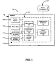
- FIG. 1 illustrates a schematic 100 depicting the physical and logical components of a mobile or hand propelled printer 102.
- the printer 102 may include a controller 104 powered by a power supply 106 and in communication with a print head 108 and a sensor suite 110.
- the sensor suite 110 in this exemplary embodiment, may include one or more position or navigation sensors 112 and one or more optical imaging sensors 114.
- the controller 104 and the sensor suite 110 cooperate to facilitate precise and accurate positioning of the print head 108 throughout printing and/or scanning operations. Precise positioning allows the printer 102 to reliably produce or print images and scan or acquire images.
- the controller 104 may include a communication interface or module 116 coupled to an image processing module 118 and an image information source 120.
- the image processing module 118 may, in turn, be communicatively coupled to a print module 122 and an image capture module 124.
- the print module 122 and image capture module 124 are, in this exemplary embodiment, communicatively coupled to a positioning module 126.
- the image information source 120 may be any type of device capable of transmitting data related to an image, picture or file to be printed by the print head 108.
- the image information source 120 may include a general purpose computing device, e.g., a desktop computing device, a laptop computing device, a mobile computing device, a personal digital assistant, a cellular phone, etc. or it may be a removable storage device, e.g., a flash memory data storage device, designed to store data such as image data. If, for example, the image information source 120 is a removable storage device, e.g., a universal serial bus (USB) storage device, the communication interface 116 may include a port, e.g., a USB port, to engage and communicatively receive the storage device.
- USB universal serial bus
- the communication interface 116 may include a wireless transceiver to allow for the wireless communication of image data between the image information source 120 and the controller 104.
- the communication interface 116 may facilitate creation of an infrared (IR) communication link, a radio-frequency (RF) communication link or any other known or contemplated communication system, method or medium.
- IR infrared
- RF radio-frequency
- the communication interface 116 may, in other alternate embodiments, be configured to communicate with the image information source 120 through one or more wired and/or wireless networks.
- the networks may include, but are not limited to, a personal area network (PAN), a local area network (LAN), a wireless local area network (WLAN), a wide area network (WAN), etc.
- PAN personal area network
- LAN local area network
- WLAN wireless local area network
- WAN wide area network
- the networks may be established in accordance with any number of standards and/or specifications such as, for example, IEEE 802.11x (where x indicates a, b, g and n, etc.), 802.16, 802.15.4, Bluetooth, Global System for Mobile Communications (GSM), code-division multiple access (CDMA), Ethernet, etc.
- GSM Global System for Mobile Communications
- CDMA code-division multiple access
- the image processing module118 may receive the image data from the communication interface 116 and process the received image data to facilitate the printing process. Alternatively, the processing of the image data may be performed by the image information source 120 or other device or module and communicated to the communication interface 116. The processed image data may, in turn, be provided to the print module 122. The print module 122 can cache or store the processed image data or may communicate the data in real-time for printing by the print head 108.
- the positioning module 126 may provide position information to the print module 122.
- the position information may be utilized to calculate the relative position of the print head 108 to a reference point defined or established on the print medium or within the image data being printed and/or scanned.
- the position information may be generated or calculated by the positioning module 126 based on signals, measurements or other information received from the one or more navigation sensors 112.
- the navigation sensors 112 may, for example, be an optoelectronic sensor, an electromechanical sensor or one or more inertial sensors configured to provide location and direction information to the printer 102 and the print head 108.
- Print medium may be any type of material or medium on which a printing substance, e.g., ink, powder, etc., may be deposited.
- the position information provided by the navigation sensors 112 may be utilized by the print module 122, via the positioning module 126, to coordinate the location of the print head 108 to a position within the processed image data provided by the image processing module 118.
- the print module 122 may then direct and control the print head 108 to dispense and deposit ink on the print medium to represent the corresponding portion of the processed image data.
- the print head 108 may be an inkjet print head having a plurality of nozzles or primitives (see FIGS. 2A and 2B for details) configured to dispense a printing substance, e.g., liquid ink droplets, on a print medium.
- the printing substance may be contained in reservoirs or cartridges.
- the reservoirs or cartridges may contain or store black ink, and/or multiple colors such as cyan ink, magenta ink, yellow ink, and black ink.
- Other embodiments may utilize other printing techniques, e.g., toner-based printers such as laser or light-emitting diode (LED) printers, solid ink printers, dye-sublimation printers, inkless printers, etc.
- LED light-emitting diode
- the image capture module 124 may receive image information from the one or more optical imaging sensors 114.
- the optical imaging sensors 114 may be charge coupled devices (CCDs) configured and arranged to capture a plurality of images representative of the surface of the print medium or other scannable medium.
- the plurality of images may be processed by the image capture module 124 and reassembled to generate a representation of the print medium or scannable medium.
- the image capture module 124 may receive positioning information from the positioning module 126 to facilitate the arrangement and reassembly of the plurality of captured images provided by the optical image sensors 114. In this manner, the printer 102 may be utilized to scan, process, store and duplicate images via the cooperation of the image capture module 124, the positioning module 126 and the print module 122.
- the image capture module 124 may, in another embodiment, be utilized to calibrate the positioning module 126. For example, an image captured by the optical image sensors 114 may be compared to the processed image data provided by the image processing module 118 to correct or compensate for accumulated positioning errors and/or to reorient the positioning module 126. For example, if the printer 102 is removed from the print medium during a printing procedure, the positioning module 126 may lose track of the reference point associated with the printing procedure.
- FIG. 2A illustrates a bottom plan view of a printing device 200 which may be constructed to include the teachings discussed in conjunction with the logical schematic 100 and the mobile or hand propelled printer 102.
- the components and elements of the printer 102 may be included in, or integral to, the printing device 200.
- the printing device 200 includes a housing 202 that supports and carries the print head 108 and the sensor suite 110 including a pair of navigation sensors 112 and one or more optical image sensors 114.
- the housing 202 may further include a cover or panel 212.
- the cover 212 may be hinged or pivotably attached to the housing 202.
- the cover 212 may protect an interior portion 214 including, for example, components and elements of the printer 102 positioned or accessible within the housing 202.
- the pair of navigation sensors 112 may be used by the positioning module 126 (see FIG. 1 ) to determine positioning information related to the optical imaging sensors 114 and/or the print head 108.
- the housing 202 supports the optical imaging sensors 114 and the print head 108 fixed relative to the pair of navigation sensors 112 such that the image and/or position information obtained by the navigation sensors 112 may be precisely correlated to the relative to the optical imaging sensors 114 and the print head 108.
- the print head 108 may be an inkjet print head having a number of nozzle arrays for different colored inks.
- the print head 108 may include a nozzle array 204 for cyan-colored ink (C), a nozzle array 206 for magenta-colored ink (M), a nozzle array 208 for yellow-colored ink (Y), and nozzle array 210 for black-colored ink (K).
- the nozzle arrays 204 to 210 of the print head 108 may be arranged adjacent to optical imaging sensors 114. This configuration allows the optical imaging sensors 114 to capture information about the ink deposited on the print medium by the print head 108 as it is dispensed. This information may be used for error correction and verification of the processed image data throughout the dispensing and/or printing processes.
- the nozzle arrays 204 to 210 in this exemplary embodiment are arranged according to color.
- the arrangement and order of the colors stored within the nozzle arrays 204 to 210 may be based on predetermined deposition orders and/or amounts necessary to create new colors by depositing and thereby mixing the colors stored within the nozzle arrays 204 to 210.
- Utilization of different base or constituent colors, e.g., colors other than CMYK, may require a different nozzle order or arrangement to produce the desired colors, color combinations, etc.
- FIG. 2B illustrates an enlarged plan view of the nozzle array 204.
- the nozzle array 204 includes a plurality of individual nozzles identified by the reference numerals 204a to 204g. As illustrated in FIG. 2B , the nozzles 204a to 204g are staggered or offset along the length of the nozzle array 204. The stagger allows for the manufacture or formation of fluid passages 212a to 212g, which correspond to the nozzles 204a to 204g, respectively.
- the fluid passages 212a to 212g may be fluidly coupled to a reservoir (not shown) containing or storing the printing substance or ink to be dispensed through the nozzles 204a to 204g.
- FIG. 2C illustrates an enlarged cross-sectional view of the exemplary nozzle 204a.
- the nozzle 204a may be formed within a casing 214 such that the fluid passage 212a is fluidly coupled to a dispensing orifice 216.
- the printing substance may be provided to the nozzle 204a via the fluid passage 212a and a dispensing chamber 218.
- a dispensing chamber 218 may be provided for each of the nozzles 204a to 204g and individually identified as 218a to 218g, respectively.
- the printing substance or ink, once delivered to the dispensing chamber 218, may be retained via capillary action.
- the nozzle 204a may further include a heating element 220 such as, for example, a resistor.
- the heating element 220 creates heat in response to an applied electric current.
- the heat creates a bubble 222 by vaporizing the printing substance.
- the printing substance within the dispensing chamber 218 may be forced through the dispensing orifice 216 and onto the surface of the print medium (not shown).
- a vacuum may be created.
- the resulting vacuum pulls or resupplies printing substance from the reservoir (not shown) into the dispensing chamber 218 via the fluid passage 212a.
- the print head 108 and print module 122 may dispense printing substance on the print medium to create an image.
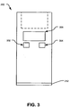
- FIG. 3 illustrates is a top plan view of the printing device 200 shown in FIG.2A .
- the printing device 200 may include a variety of user controls, buttons, touch screens, etc., based on the functionality designed into or supported by the controller 104 shown in FIG. 1 .
- the printing device 200 includes a print control input 302, a scan control input 304 and a display 306 communicatively coupled to the controller 104.
- the print control input 302 may provide a signal to the controller 104 that can be utilized to initiate/resume a print operation.
- the scan control input 304 may provide a signal to the controller 104 that can be utilized to initiate/resume a scan operation.
- the display 306 which may be a passive display, an interactive display, etc., may provide the user with a variety of information.
- the information may relate to the current operating status of the printing device 200 (e.g., printing, ready to print, scanning, ready to scan, receiving print image, transmitting print image, transmitting scan image, etc.), power of the battery, errors (e.g., scanning/positioning/printing error, etc.), or instructions (e.g., "position device over a printed portion of the image for reorientation," etc.).
- the display 306 is an interactive display it may provide a control interface in addition to, or as an alternative from, the control inputs 302 and 304.
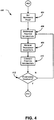
- FIG. 4 depicts a flow diagram illustrating an exemplary positioning operation 400 that may be performed by the printing device 200 shown in FIG. 2 .
- the positioning operation 400 may begin with the initiation of a scanning or a printing operation.
- the print control input 302 may provide a signal to the controller 104 (see FIG. 1 ) to initiate a print operation
- the scan control input 304 may provide a signal to the controller 104 to initiate a scan operation.
- a reference point on the printing medium may be established by the positioning module 126.
- the user may be instructed via text or graphics provided by the display 306 to activate one of the inputs 302, 304 when the printing device 200 is positioned in a desired starting location.
- the user may preposition the printing device 200 in the desired starting location and orientation and the reference point may be established upon activation of the appropriate input 302, 304.
- the positioning module 126 may utilize information provided by the navigation sensors 112 to determine position information, e.g., translational and/or rotational changes relative to the reference point, for the printing device 200.
- the translational changes may be determined by tracking incremental changes of the positions of the navigation sensors along a two-dimensional coordinate system, e.g., ⁇ x and ⁇ y.
- Rotational changes may be determined by tracking incremental changes in the angle of the printing device, e.g., ⁇ , with respect to, e.g., the y-axis.
- transitional and/or rotational changes may be determined by the positioning module comparing consecutive navigational images taken by the navigation sensors 112 to detect these movements.
- the positioning module 126 may further receive the processed image data from the image processing module 118. If all or part of an image has been previously deposited or printed at a given location, the optical image sensors 114 may be utilized to verify the accuracy of the calculated position location with respect to the received processed image data. For example, the optical image sensors 114 may sample the deposited image (or image to be scanned) and compare that sample to a corresponding position within the received processed image data. This verification process may further note and compensate for images in which the printing and/or deposition is incomplete.
- the positioning module 126 may correct for differences and deviations between the calculated position location and the received processed image data. For example, with enough information, e.g., sufficient material deposited in the location scanned by the optical image sensors 114, the positioning module 126 may offset and align the position information to ensure that the two images match. If the positioning module 126 is unable to determine an appropriate offset based on the available information, the optical image sensors 114 may be utilized to gather more information, identify patterns, etc. The additional information and/or patterns may, in turn, be utilized by the positioning module 126 to determine the offset necessary to align the calculated position location and the received processed image data. Correction and compensation may be performed continually or periodically based on, for example, image complexity, available processing power, desired resolution, etc.
- the positioning operation 400 and positioning calculations may be evaluated. If the position information is determined to be accurate, then at block 414 the positioning operation 400 may be completed. If the position information is incomplete, inaccurate or otherwise unacceptable, then positioning operation 400 may return to block 406 and begin the process again.
- FIG. 5 depicts a flow diagram illustrating a printing operation 500 that may be performed by the printing device 200.
- the printing operation 500 may begin or be initiated by, for example, a signal provided by the print control input 302.
- the print module 122 may receive processed image data from the image processing module 118.
- the image data may be received in a raw or unprocessed format from the image information source 120 and processed for printing by the image processing module 118.
- the image data may be preprocessed by the image information source 120 and communicated to the print module 122 as.discussed in connection with FIG. 1 .
- the display 306 may indicate that the printing device 200 is ready to print the processed image data.
- the display 306 may also provide a thumbnail representation of the processed image data.
- the thumbnail image provided by the display 306 may be utilized to indicate the status of the printing operation 500. For example, thumbnail image may be erased, shaded or otherwise modified as the printing device 200 dispenses and prints the processed image data on a print medium.
- the print module 122 may receive a signal representative of a print command generated from a user activating the print control input 302 in block 516.
- the print module 122 may further receive positioning information from the positioning module 126.
- the print module 122 may then determine whether to deposit printing substance, e.g., one or more colors of ink, at the given location on the surface of the print medium. For example, the determination to print or deposit ink may be a function of the total drop volume to be placed at a given location on the surface of the print medium and the drop volume previously deposited at that location. If additional printing or deposition is to occur, then at block 514 the print module 122 may cause the print head 108 to dispense an appropriate amount of the printing substance as the printing device 200 is moved or propelled across the surface of the print medium by the user. The printing operation 500 may, in turn, return to the block 510 to receive additional positioning information in preparation for further deposition.
- printing substance e.g., one or more colors of ink
- the printing operation 500 may determine if the print job has been completed. The determination of whether the print job is complete may be a function of the printed volume versus the total print volume. Alternatively, the determination to end the printing operation 500 may be reached even if the printed volume is less than the total print volume. For example, the end of the printing operation 500 may occur when the printed volume is ninety-five percent (95%) of the total print volume. If the print job is completed, then at block 518 the printing operation 500 ends. If the print job is not complete, then the printing operation 500 may return to the block 510 to receive additional positioning information in preparation for further deposition.
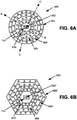
- FIGS. 6A and 6B illustrate exemplary physical arrangements of the print head 108 including nozzle arrays configured to optimize hand-held printing.
- the user may propel or move the printing device 200 in a side to side motion as indicated by the arrow A (see FIG. 2A ).
- the back and forth motion of the printing device 200 moves and positions the linear nozzle arrays 204 to 210 to desired positions over the surface of the print medium.
- Printing substances, and in particular CMYK inks, which may be dispensed by the printing device 200, as directed by the print module 122, are often calibrated, tested and otherwise arranged to create or provide colors based on their deposition order and/or amounts.
- FIG. 6A illustrates one embodiment of an exemplary print head 108 that includes a concentric circular nozzle array 600 optimized for multidirectional printing.
- the concentric circular nozzle array 600 may include a nozzle array 604 for cyan-colored ink (C), a nozzle array 606 for magenta-colored ink (M), a nozzle array 608 for yellow-colored ink (Y), and nozzle array 610 for black-colored ink (K).
- the each of the circular nozzle arrays 604 to 610 may be concentric around or equidistant to a reference point 602.
- the reference point 602 may further be the location of the optical image sensors 114.
- the configuration and relative position of the circular nozzles 604 to 610 allows for multi-color dispensing and printing in variety or multitude of vectors or directions.
- the user may move the printing device 200 in any direction or vector along the surface of the print medium and dispense printing substances.
- the vector arrows B, C and D indicate three (3) distinct directions in which the printing device 200 may be propelled by the user. It will be understood that given the circular arrangement of the concentric circular nozzle array 600 any number of directions or vectors may be utilized.
- the relative position and alignment of the circular nozzle arrays 604 to 610 remain fixed and constant with respect to each other and the reference point 602.
- the leading edge portion (near the label B) and trailing edge portion (near the label B') of the circular arrangement of the nozzle array 600 effectively provides for two, albeit mirror images of each other, separate arrays which may be utilized to dispense printing substances.
- the print module 122 may be utilized to control, time and otherwise direct the dispensing of printing substances from, for example, the circular nozzle array 606 disposed substantially adjacent to the leading edge portion (near the label B) and the circular nozzle array 606 disposed substantially adjacent to the trailing edge portion (near the label B') as the printing device 200 is moved along the printing surface.
- FIG. 6B illustrates another embodiment of an exemplary print head 108 that includes a polygon nozzle array 600' optimized for multidirectional printing.
- the polygon nozzle array 600' may include a nozzle array 604' for cyan-colored ink (C), a nozzle array 606' for magenta-colored ink (M), a nozzle array 608' for yellow-colored ink (Y), and nozzle array 610' for black-colored ink (K).
- the polygon nozzle array 606' may be substantially concentric around or substantially equidistant to a reference point 602'.
- the reference point 602' may further be the location of the optical image sensors 114.
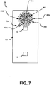
- FIG. 7 illustrates an alternative bottom plan view of a printing device 700 which may be constructed to include the teachings discussed in conjunction with the logical schematic 100 and the mobile or hand propelled printer 102.
- the printing device 700 may include the concentric circular nozzle array 600 and an imaging array 714 (see the imaging array 114 in FIG. 6A ) mounted in the printer housing 702.
- the imaging array 714 may be mounted or positioned within the center or central portion of the circular nozzle array 600.
- the imaging array 714 may be, for example, a line scanner, optical sensors such as a charge coupled device (CCD) or any other imaging or scanning device.
- CCD charge coupled device
- the housing 702 further includes a locking mechanism 704 disposed substantially adjacent to the concentric circular nozzle array 600.
- the locking mechanism 704 may be a spring loaded latch configured to releasably cooperate with a protective cap or cap 800 (see FIGS. 8A to 8C ).
- the locking mechanism 704 may be a friction lock that utilizes a slip or interference fit with the housing 702 to engage and secure the cap 800.
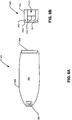
- FIGS. 8A and 8B illustrate a flexible ink reservoir 800 constructed in accordance with the teachings disclosed herein.
- the ink reservoir 800 may include a flexible and/or semi-rigid container or walls 802.
- the container 802 may be constructed from tear or puncture resistant plastic, a layered Mylar® or other malleable material.
- the container 802 may further be constructed from a material that is chemically inert with respect to the printing substance or ink stored within the interior 804.
- the container 802 may be divided into separate chambers, interiors, etc. in order to store different printing substances.
- the ink reservoir 800 may further include a fluid port 806 provided or carried as an integral portion of the container 802.
- the fluid port 806 may be bonded as a portion of the structure wall.
- the fluid port 806 may be constructed from a material complimentary to the material of the container 802. In this way, the fluid port 806 and the container 802 may be bonded or joined to seal the ink reservoir 800 against fluid leaks. Bonding may be achieved by friction or sonically welding the material of the fluid port 806 to the material of the container 802.
- the fluid port 806 may be a two-piece tapered component configured to form a compression or pressure seal and secure the material of container 802.
- the ink reservoir 800 may further include a printing substrate 808 bonded, sealed or otherwise joined to the material of the container 802.
- the printing substrate 808 may provide a controllable fluid connection between the printing substance stored within the interior 804 and the print head 108.
- the printing substrate 808 may include componentry and functionality of the print head 108.
- FIG. 8B illustrates an enlarged cross-sectional view of the fluid port 806.
- the body 810 includes a passage 812 formed therethrough.
- the passage 812 may be utilized to establish a fluid connection between the printing substance (not shown) stored in the interior 804 and the environs surrounding the ink reservoir 800.
- the fluid port 806 may include a resealable valve or septum 814 to control the fluid flow and movement to and from the interior 804.
- the septum 814 may be a flexible or deformable seal carried within the passage 812 of the fluid port 806.
- the septum 814 may further include a seam or discontinuity 816 that may be utilized for refilling of the interior 804. For example, the seam 816 may be forced open to allow refilling, while simultaneously engaging the exterior of the filling device (see FIG. 9 ) to prevent leakage.
- the fluid port 806 may further include a groove 818 formed about the exterior surface of the body 810.
- the groove 818 may be sized to accept the material of the container 802.
- the material may, in turn, be joined or otherwise bonded to the fluid port 806 to form a liquid and/or pressure tight seal.
- the bonding may be accomplished by heating material of the body 810 adjacent to the groove 818 near, for example, the exterior surface 818a.
- the complementary materials of the body 810 and the container 802 may, in turn, co-mingle to form or establish a tight seal.
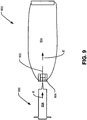
- FIG. 9 illustrates a refilling operation that may be conducted in conjunction with the ink reservoir 800.
- a syringe 900 may be utilized to provide or transfer the printing substance to the interior 804 of the ink reservoir 800.
- a needle portion 902 of the syringe 900 may be inserted or forced through the seam 816.
- the septum 814 expands and deforms to allow the needle portion 902 to pass into the interior 804 while simultaneously forming a seal around the exterior surface of the needle portion 902.
- the interior 904 of the syringe 900 may be fluidly coupled to the interior 804 of the ink reservoir 800.
- the printing substance may, as indicated by the arrows E and E', be transferred, pumped or otherwise communicated through the syringe 900 to the ink reservoir 800. This process may be reversed to remove printing substance from interior 804 or may be accomplished using a different syringe or other fluid communication device.
Landscapes
- Ink Jet (AREA)
- Accessory Devices And Overall Control Thereof (AREA)
Claims (15)
- Tintenreservoir (800) für einen tragbaren Drucker (102), wobei das Tintenreservoir (800) folgendes umfasst:ein flexibles Gehäuse (802), das in einem inneren Bereich des tragbaren Druckers (102) angeordnet ist;ein Drucksubstrat (808), das in Kontakt mit dem flexiblen Gehäuse (802) ist und das konfiguriert ist, eine Drucksubstanz, die in dem flexiblen Gehäuse (802) aufbewahrt wird, fluidisch mit einem Druckkopfbereich (108) des tragbaren Druckers (102) zu verbinden; undeinen Fluidanschluss (806), der in fluidischer Verbindung mit einem Inneren (804) des flexiblen Gehäuses (802) ist, wobei der Fluidanschluss (806) ein wieder abdichtbares Ventil (814) umfasst.
- Tintenreservoir (800) nach Anspruch 1, worin der Fluidanschluss (806) ein flexibles Septum einschließt.
- Tintenreservoir (800) nach Anspruch 1 oder 2, worin das flexible Gehäuse (802) konfiguriert ist, eine Vielzahl von Fluidkammern einzuschließen.
- Tintenreservoir (800) nach Anspruch 3, worin jede der Vielzahl von Fluidkammern in Verbindung mit dem Fluidanschluss (806) ist.
- Tintenreservoir (800) nach irgendeinem der Ansprüche 1 bis 4, worin der Fluidanschluss (806) und das Drucksubstrat (808) eine Fluidschnittstelle bilden.
- Tintenreservoir (800) nach irgendeinem der Ansprüche 1 bis 5, das weiterhin ein Druckergehäuse umfasst, das konfiguriert ist, den Druckkopfbereich (108) des tragbaren Druckers (102) zu lagern.
- Verfahren zum Konfigurieren eines Tintenreservoirs (800) für einen tragbaren Drucker (102), wobei das Verfahren umfasst:Bilden eines flexiblen Gehäuses (802), das in einem inneren Bereich des tragbaren Druckers (102) angeordnet ist;Anschließen eines Drucksubstrats (808) an das flexible Gehäuse (802), wobei das Drucksubstrat (808) konfiguriert ist, eine Drucksubstanz, die in dem flexiblen Gehäuse (802) aufbewahrt wird, fluidisch mit einem Druckkopfbereich (108) des tragbaren Druckers (102) zu verbinden; undAbdichten eines Fluidanschlusses (806), der ein wiederabdichtbares Ventil (814) innerhalb eines flexiblen Wandbereichs des flexiblen Gehäuses (802) umfasst, so dass der Fluidanschluss (806) in Fluidverbindung mit einem Inneren (804) des flexiblen Gehäuses (802) ist.
- Verfahren nach Anspruch 7, worin das Abdichten des Fluidanschlusses (806) die Verwendung eines flexiblen Septums (814) einschließt.
- Verfahren nach Anspruch 7 oder 8, worin das Bilden des flexiblen Gehäuses (802) das Bilden einer Vielzahl von Fluidkammern einschließt.
- Verfahren nach Anspruch 9, worin jede der Vielzahl von Fluidkammern sich in Verbindung mit dem Fluidanschluss (806) befindet.
- Verfahren nach irgendeinem der Ansprüche 7 bis 10, worin das Anschließen des Drucksubstrats (808) Hitzeabdichten des Drucksubstrats (808) zu dem flexiblen Gehäuse (802) einschließt.
- Verfahren nach irgendeinem der Ansprüche 7 bis 11, das weiterhin das Füllen des flexiblen Gehäuses (802) mit der Drucksubstanz mit einer Wiederauffüllspritze (900) umfasst.
- Tintenreservoir (800) nach irgendeinem der Ansprüche 1 bis 4 oder 5, worin das wiederabdichtbare Ventil (814) eine Fluidflussbewegung zu und von dem Inneren (804) des flexiblen Gehäuses (802) kontrolliert.
- Tintenreservoir (800) nach irgendeinem der Ansprüche 1 bis 4, 5 oder 13, worin das wiederabdichtbare Ventil (814) eine Fuge (816) einschließt, die geformt ist, so dass sie dazu gebracht werden kann, sich zu öffnen durch eine Füllvorrichtung.
- Tintenreservoir (800) nach einem der Ansprüche 1 bis 4, 5, 13, 14, worin der Fluidanschluss (806) eine Kerbe (818) einschließt, die an der Außenseite des Fluidanschlusses (806) ausgebildet ist, und
worin das flexible Gehäuse an die Kerbe (818) des Fluidanschlusses (806) gebondet ist.
Applications Claiming Priority (3)
| Application Number | Priority Date | Filing Date | Title |
|---|---|---|---|
| US89270307P | 2007-03-02 | 2007-03-02 | |
| US91302707P | 2007-04-20 | 2007-04-20 | |
| PCT/US2008/055679 WO2008109535A2 (en) | 2007-03-02 | 2008-03-03 | Ink supply for a hand-held ink jet printer |
Publications (3)
| Publication Number | Publication Date |
|---|---|
| EP2114686A2 EP2114686A2 (de) | 2009-11-11 |
| EP2114686A4 EP2114686A4 (de) | 2010-05-26 |
| EP2114686B1 true EP2114686B1 (de) | 2012-05-16 |
Family
ID=39739055
Family Applications (1)
| Application Number | Title | Priority Date | Filing Date |
|---|---|---|---|
| EP08731267A Not-in-force EP2114686B1 (de) | 2007-03-02 | 2008-03-03 | Tintenzufuhr für tragbaren tintenstrahldrucker |
Country Status (4)
| Country | Link |
|---|---|
| EP (1) | EP2114686B1 (de) |
| JP (2) | JP2010520822A (de) |
| CN (1) | CN101641218B (de) |
| WO (1) | WO2008109535A2 (de) |
Families Citing this family (2)
| Publication number | Priority date | Publication date | Assignee | Title |
|---|---|---|---|---|
| JP2015174264A (ja) * | 2014-03-14 | 2015-10-05 | セイコーエプソン株式会社 | 注入方法、液体収容容器 |
| WO2016015201A1 (zh) * | 2014-07-28 | 2016-02-04 | 冯林 | 一种便携式数字印刷装置 |
Family Cites Families (10)
| Publication number | Priority date | Publication date | Assignee | Title |
|---|---|---|---|---|
| US4412232A (en) * | 1982-04-15 | 1983-10-25 | Ncr Corporation | Ink jet printer |
| JPH0440987U (de) * | 1990-08-01 | 1992-04-07 | ||
| US6585359B1 (en) * | 1997-06-04 | 2003-07-01 | Hewlett-Packard Development Company, L.P. | Ink container providing pressurized ink with ink level sensor |
| JP2000190678A (ja) * | 1998-12-28 | 2000-07-11 | Pentel Corp | インキタンク |
| JP4175233B2 (ja) * | 2003-05-29 | 2008-11-05 | ソニー株式会社 | 記録液、液体カートリッジ、液体吐出装置及び液体吐出方法 |
| US6676252B2 (en) * | 2002-04-24 | 2004-01-13 | Hewlett-Packard Development Company, L.P. | Printer ink cartridge and method of assembling same |
| JP4125206B2 (ja) * | 2002-09-30 | 2008-07-30 | キヤノン株式会社 | インク供給システム |
| JP2004358802A (ja) * | 2003-06-04 | 2004-12-24 | Ricoh Co Ltd | インク袋の再充填方法及びリサイクルインク袋並びにインクカートリッジ |
| CA2616928C (en) * | 2005-08-02 | 2014-10-07 | Baxter International Inc. | Multiple chamber container |
| CA2617638C (en) * | 2005-08-03 | 2013-01-08 | Societe Bic | A liquid droplet ejecting head, a writing instrument comprising such a head, and a method of ejecting liquid droplets from same |
-
2008
- 2008-03-03 JP JP2009551889A patent/JP2010520822A/ja active Pending
- 2008-03-03 CN CN2008800069480A patent/CN101641218B/zh not_active Expired - Fee Related
- 2008-03-03 EP EP08731267A patent/EP2114686B1/de not_active Not-in-force
- 2008-03-03 WO PCT/US2008/055679 patent/WO2008109535A2/en active Application Filing
-
2013
- 2013-06-12 JP JP2013124041A patent/JP2013208911A/ja not_active Withdrawn
Also Published As
| Publication number | Publication date |
|---|---|
| EP2114686A2 (de) | 2009-11-11 |
| WO2008109535A3 (en) | 2008-10-30 |
| CN101641218A (zh) | 2010-02-03 |
| JP2010520822A (ja) | 2010-06-17 |
| EP2114686A4 (de) | 2010-05-26 |
| JP2013208911A (ja) | 2013-10-10 |
| WO2008109535A2 (en) | 2008-09-12 |
| CN101641218B (zh) | 2012-10-03 |
Similar Documents
| Publication | Publication Date | Title |
|---|---|---|
| US8128192B1 (en) | Cap design for an inkjet print head with hand-held imaging element arrangement with integrated cleaning mechanism | |
| CN101626897B (zh) | 手持打印机和用于维护手持打印机上的喷墨件的方法 | |
| US6543893B2 (en) | Solid and semi-flexible body inkjet printing system | |
| US8733915B2 (en) | Cartridge | |
| US8594922B1 (en) | Method and apparatus for determining a position of a handheld image translation device over a medium while using the handheld image translation device to translate an image onto the medium | |
| EP0875379A2 (de) | Druckkopfanordnung mit mehreren Patronen zur Anwendung in einem Tintenstrahldrucksystem | |
| US8077350B1 (en) | Device and method for dispensing white ink | |
| JP2007105883A (ja) | インクジェット記録装置 | |
| US9111201B1 (en) | Hand-held printing device and method for tuning ink jet color for printing on colored paper | |
| EP2114686B1 (de) | Tintenzufuhr für tragbaren tintenstrahldrucker | |
| EP0945271A2 (de) | Ausrichtungskupplungsvorrichtung zum manuellen Verbinden einer Tintenversorgung mit einer Tintenstrahldruckpatrone | |
| US8827442B1 (en) | Print head configuration for hand-held printing | |
| JP2000301732A (ja) | インクジェット記録装置 | |
| JP2002067317A (ja) | インクジェット式記録ヘッド、及びそれを用いた画像記録装置 | |
| US6929356B2 (en) | Container of consumable supplies for a printer and printer utilizing the container | |
| JP2007105882A (ja) | インクジェット記録装置およびインクジェット記録装置に用いるインクジェットヘッドのインク充填方法 | |
| EP1308290B1 (de) | Dualmoduskommunikationsgerät für ein Gerät zum Ausstossen von Flüssigkeit | |
| US8043015B1 (en) | Detecting edge of a print medium with a handheld image translation device | |
| JP2019048416A (ja) | 画像記録装置 | |
| JP2002210929A (ja) | インクジェットプリンタ | |
| JP2006327062A (ja) | 液体吐出ヘッドおよび液体吐出装置 |
Legal Events
| Date | Code | Title | Description |
|---|---|---|---|
| PUAI | Public reference made under article 153(3) epc to a published international application that has entered the european phase |
Free format text: ORIGINAL CODE: 0009012 |
|
| 17P | Request for examination filed |
Effective date: 20090901 |
|
| AK | Designated contracting states |
Kind code of ref document: A2 Designated state(s): AT BE BG CH CY CZ DE DK EE ES FI FR GB GR HR HU IE IS IT LI LT LU LV MC MT NL NO PL PT RO SE SI SK TR |
|
| A4 | Supplementary search report drawn up and despatched |
Effective date: 20100428 |
|
| REG | Reference to a national code |
Ref country code: DE Ref legal event code: R079 Ref document number: 602008015638 Country of ref document: DE Free format text: PREVIOUS MAIN CLASS: B41J0002175000 Ipc: B41J0003360000 |
|
| GRAP | Despatch of communication of intention to grant a patent |
Free format text: ORIGINAL CODE: EPIDOSNIGR1 |
|
| RIC1 | Information provided on ipc code assigned before grant |
Ipc: B41J 2/175 20060101ALI20110927BHEP Ipc: B41J 3/36 20060101AFI20110927BHEP |
|
| GRAS | Grant fee paid |
Free format text: ORIGINAL CODE: EPIDOSNIGR3 |
|
| GRAA | (expected) grant |
Free format text: ORIGINAL CODE: 0009210 |
|
| DAX | Request for extension of the european patent (deleted) | ||
| AK | Designated contracting states |
Kind code of ref document: B1 Designated state(s): AT BE BG CH CY CZ DE DK EE ES FI FR GB GR HR HU IE IS IT LI LT LU LV MC MT NL NO PL PT RO SE SI SK TR |
|
| REG | Reference to a national code |
Ref country code: GB Ref legal event code: FG4D |
|
| REG | Reference to a national code |
Ref country code: CH Ref legal event code: EP |
|
| REG | Reference to a national code |
Ref country code: AT Ref legal event code: REF Ref document number: 557891 Country of ref document: AT Kind code of ref document: T Effective date: 20120615 |
|
| REG | Reference to a national code |
Ref country code: IE Ref legal event code: FG4D |
|
| REG | Reference to a national code |
Ref country code: DE Ref legal event code: R096 Ref document number: 602008015638 Country of ref document: DE Effective date: 20120712 |
|
| REG | Reference to a national code |
Ref country code: NL Ref legal event code: VDEP Effective date: 20120516 |
|
| REG | Reference to a national code |
Ref country code: LT Ref legal event code: MG4D Effective date: 20120516 |
|
| PG25 | Lapsed in a contracting state [announced via postgrant information from national office to epo] |
Ref country code: PL Free format text: LAPSE BECAUSE OF FAILURE TO SUBMIT A TRANSLATION OF THE DESCRIPTION OR TO PAY THE FEE WITHIN THE PRESCRIBED TIME-LIMIT Effective date: 20120516 Ref country code: CY Free format text: LAPSE BECAUSE OF FAILURE TO SUBMIT A TRANSLATION OF THE DESCRIPTION OR TO PAY THE FEE WITHIN THE PRESCRIBED TIME-LIMIT Effective date: 20120516 Ref country code: SE Free format text: LAPSE BECAUSE OF FAILURE TO SUBMIT A TRANSLATION OF THE DESCRIPTION OR TO PAY THE FEE WITHIN THE PRESCRIBED TIME-LIMIT Effective date: 20120516 Ref country code: LT Free format text: LAPSE BECAUSE OF FAILURE TO SUBMIT A TRANSLATION OF THE DESCRIPTION OR TO PAY THE FEE WITHIN THE PRESCRIBED TIME-LIMIT Effective date: 20120516 Ref country code: FI Free format text: LAPSE BECAUSE OF FAILURE TO SUBMIT A TRANSLATION OF THE DESCRIPTION OR TO PAY THE FEE WITHIN THE PRESCRIBED TIME-LIMIT Effective date: 20120516 Ref country code: IS Free format text: LAPSE BECAUSE OF FAILURE TO SUBMIT A TRANSLATION OF THE DESCRIPTION OR TO PAY THE FEE WITHIN THE PRESCRIBED TIME-LIMIT Effective date: 20120916 Ref country code: NO Free format text: LAPSE BECAUSE OF FAILURE TO SUBMIT A TRANSLATION OF THE DESCRIPTION OR TO PAY THE FEE WITHIN THE PRESCRIBED TIME-LIMIT Effective date: 20120816 |
|
| REG | Reference to a national code |
Ref country code: AT Ref legal event code: MK05 Ref document number: 557891 Country of ref document: AT Kind code of ref document: T Effective date: 20120516 |
|
| PG25 | Lapsed in a contracting state [announced via postgrant information from national office to epo] |
Ref country code: LV Free format text: LAPSE BECAUSE OF FAILURE TO SUBMIT A TRANSLATION OF THE DESCRIPTION OR TO PAY THE FEE WITHIN THE PRESCRIBED TIME-LIMIT Effective date: 20120516 Ref country code: PT Free format text: LAPSE BECAUSE OF FAILURE TO SUBMIT A TRANSLATION OF THE DESCRIPTION OR TO PAY THE FEE WITHIN THE PRESCRIBED TIME-LIMIT Effective date: 20120917 Ref country code: SI Free format text: LAPSE BECAUSE OF FAILURE TO SUBMIT A TRANSLATION OF THE DESCRIPTION OR TO PAY THE FEE WITHIN THE PRESCRIBED TIME-LIMIT Effective date: 20120516 Ref country code: GR Free format text: LAPSE BECAUSE OF FAILURE TO SUBMIT A TRANSLATION OF THE DESCRIPTION OR TO PAY THE FEE WITHIN THE PRESCRIBED TIME-LIMIT Effective date: 20120817 Ref country code: HR Free format text: LAPSE BECAUSE OF FAILURE TO SUBMIT A TRANSLATION OF THE DESCRIPTION OR TO PAY THE FEE WITHIN THE PRESCRIBED TIME-LIMIT Effective date: 20120516 |
|
| PG25 | Lapsed in a contracting state [announced via postgrant information from national office to epo] |
Ref country code: BE Free format text: LAPSE BECAUSE OF FAILURE TO SUBMIT A TRANSLATION OF THE DESCRIPTION OR TO PAY THE FEE WITHIN THE PRESCRIBED TIME-LIMIT Effective date: 20120516 |
|
| PG25 | Lapsed in a contracting state [announced via postgrant information from national office to epo] |
Ref country code: DK Free format text: LAPSE BECAUSE OF FAILURE TO SUBMIT A TRANSLATION OF THE DESCRIPTION OR TO PAY THE FEE WITHIN THE PRESCRIBED TIME-LIMIT Effective date: 20120516 Ref country code: EE Free format text: LAPSE BECAUSE OF FAILURE TO SUBMIT A TRANSLATION OF THE DESCRIPTION OR TO PAY THE FEE WITHIN THE PRESCRIBED TIME-LIMIT Effective date: 20120516 Ref country code: AT Free format text: LAPSE BECAUSE OF FAILURE TO SUBMIT A TRANSLATION OF THE DESCRIPTION OR TO PAY THE FEE WITHIN THE PRESCRIBED TIME-LIMIT Effective date: 20120516 Ref country code: NL Free format text: LAPSE BECAUSE OF FAILURE TO SUBMIT A TRANSLATION OF THE DESCRIPTION OR TO PAY THE FEE WITHIN THE PRESCRIBED TIME-LIMIT Effective date: 20120516 Ref country code: RO Free format text: LAPSE BECAUSE OF FAILURE TO SUBMIT A TRANSLATION OF THE DESCRIPTION OR TO PAY THE FEE WITHIN THE PRESCRIBED TIME-LIMIT Effective date: 20120516 Ref country code: CZ Free format text: LAPSE BECAUSE OF FAILURE TO SUBMIT A TRANSLATION OF THE DESCRIPTION OR TO PAY THE FEE WITHIN THE PRESCRIBED TIME-LIMIT Effective date: 20120516 Ref country code: SK Free format text: LAPSE BECAUSE OF FAILURE TO SUBMIT A TRANSLATION OF THE DESCRIPTION OR TO PAY THE FEE WITHIN THE PRESCRIBED TIME-LIMIT Effective date: 20120516 |
|
| PG25 | Lapsed in a contracting state [announced via postgrant information from national office to epo] |
Ref country code: IT Free format text: LAPSE BECAUSE OF FAILURE TO SUBMIT A TRANSLATION OF THE DESCRIPTION OR TO PAY THE FEE WITHIN THE PRESCRIBED TIME-LIMIT Effective date: 20120516 |
|
| PLBE | No opposition filed within time limit |
Free format text: ORIGINAL CODE: 0009261 |
|
| STAA | Information on the status of an ep patent application or granted ep patent |
Free format text: STATUS: NO OPPOSITION FILED WITHIN TIME LIMIT |
|
| 26N | No opposition filed |
Effective date: 20130219 |
|
| PG25 | Lapsed in a contracting state [announced via postgrant information from national office to epo] |
Ref country code: ES Free format text: LAPSE BECAUSE OF FAILURE TO SUBMIT A TRANSLATION OF THE DESCRIPTION OR TO PAY THE FEE WITHIN THE PRESCRIBED TIME-LIMIT Effective date: 20120827 |
|
| REG | Reference to a national code |
Ref country code: DE Ref legal event code: R097 Ref document number: 602008015638 Country of ref document: DE Effective date: 20130219 |
|
| PG25 | Lapsed in a contracting state [announced via postgrant information from national office to epo] |
Ref country code: BG Free format text: LAPSE BECAUSE OF FAILURE TO SUBMIT A TRANSLATION OF THE DESCRIPTION OR TO PAY THE FEE WITHIN THE PRESCRIBED TIME-LIMIT Effective date: 20120816 |
|
| PG25 | Lapsed in a contracting state [announced via postgrant information from national office to epo] |
Ref country code: MC Free format text: LAPSE BECAUSE OF NON-PAYMENT OF DUE FEES Effective date: 20130331 |
|
| REG | Reference to a national code |
Ref country code: CH Ref legal event code: PL |
|
| REG | Reference to a national code |
Ref country code: IE Ref legal event code: MM4A |
|
| PG25 | Lapsed in a contracting state [announced via postgrant information from national office to epo] |
Ref country code: CH Free format text: LAPSE BECAUSE OF NON-PAYMENT OF DUE FEES Effective date: 20130331 Ref country code: IE Free format text: LAPSE BECAUSE OF NON-PAYMENT OF DUE FEES Effective date: 20130303 Ref country code: LI Free format text: LAPSE BECAUSE OF NON-PAYMENT OF DUE FEES Effective date: 20130331 |
|
| PG25 | Lapsed in a contracting state [announced via postgrant information from national office to epo] |
Ref country code: MT Free format text: LAPSE BECAUSE OF FAILURE TO SUBMIT A TRANSLATION OF THE DESCRIPTION OR TO PAY THE FEE WITHIN THE PRESCRIBED TIME-LIMIT Effective date: 20120516 |
|
| PG25 | Lapsed in a contracting state [announced via postgrant information from national office to epo] |
Ref country code: TR Free format text: LAPSE BECAUSE OF FAILURE TO SUBMIT A TRANSLATION OF THE DESCRIPTION OR TO PAY THE FEE WITHIN THE PRESCRIBED TIME-LIMIT Effective date: 20120516 |
|
| PG25 | Lapsed in a contracting state [announced via postgrant information from national office to epo] |
Ref country code: LU Free format text: LAPSE BECAUSE OF NON-PAYMENT OF DUE FEES Effective date: 20130303 Ref country code: HU Free format text: LAPSE BECAUSE OF FAILURE TO SUBMIT A TRANSLATION OF THE DESCRIPTION OR TO PAY THE FEE WITHIN THE PRESCRIBED TIME-LIMIT; INVALID AB INITIO Effective date: 20080303 |
|
| REG | Reference to a national code |
Ref country code: FR Ref legal event code: PLFP Year of fee payment: 9 |
|
| PGFP | Annual fee paid to national office [announced via postgrant information from national office to epo] |
Ref country code: FR Payment date: 20160328 Year of fee payment: 9 Ref country code: GB Payment date: 20160329 Year of fee payment: 9 |
|
| PGFP | Annual fee paid to national office [announced via postgrant information from national office to epo] |
Ref country code: DE Payment date: 20160331 Year of fee payment: 9 |
|
| REG | Reference to a national code |
Ref country code: DE Ref legal event code: R119 Ref document number: 602008015638 Country of ref document: DE |
|
| GBPC | Gb: european patent ceased through non-payment of renewal fee |
Effective date: 20170303 |
|
| REG | Reference to a national code |
Ref country code: FR Ref legal event code: ST Effective date: 20171130 |
|
| PG25 | Lapsed in a contracting state [announced via postgrant information from national office to epo] |
Ref country code: DE Free format text: LAPSE BECAUSE OF NON-PAYMENT OF DUE FEES Effective date: 20171003 Ref country code: FR Free format text: LAPSE BECAUSE OF NON-PAYMENT OF DUE FEES Effective date: 20170331 |
|
| PG25 | Lapsed in a contracting state [announced via postgrant information from national office to epo] |
Ref country code: GB Free format text: LAPSE BECAUSE OF NON-PAYMENT OF DUE FEES Effective date: 20170303 |