EP2114673B1 - Sicherheitsdokument - Google Patents
Sicherheitsdokument Download PDFInfo
- Publication number
- EP2114673B1 EP2114673B1 EP08707586A EP08707586A EP2114673B1 EP 2114673 B1 EP2114673 B1 EP 2114673B1 EP 08707586 A EP08707586 A EP 08707586A EP 08707586 A EP08707586 A EP 08707586A EP 2114673 B1 EP2114673 B1 EP 2114673B1
- Authority
- EP
- European Patent Office
- Prior art keywords
- layer
- watermark
- security document
- security
- carrier substrate
- Prior art date
- Legal status (The legal status is an assumption and is not a legal conclusion. Google has not performed a legal analysis and makes no representation as to the accuracy of the status listed.)
- Revoked
Links
Images


Classifications
-
- B—PERFORMING OPERATIONS; TRANSPORTING
- B42—BOOKBINDING; ALBUMS; FILES; SPECIAL PRINTED MATTER
- B42D—BOOKS; BOOK COVERS; LOOSE LEAVES; PRINTED MATTER CHARACTERISED BY IDENTIFICATION OR SECURITY FEATURES; PRINTED MATTER OF SPECIAL FORMAT OR STYLE NOT OTHERWISE PROVIDED FOR; DEVICES FOR USE THEREWITH AND NOT OTHERWISE PROVIDED FOR; MOVABLE-STRIP WRITING OR READING APPARATUS
- B42D25/00—Information-bearing cards or sheet-like structures characterised by identification or security features; Manufacture thereof
- B42D25/30—Identification or security features, e.g. for preventing forgery
- B42D25/333—Watermarks
-
- B—PERFORMING OPERATIONS; TRANSPORTING
- B42—BOOKBINDING; ALBUMS; FILES; SPECIAL PRINTED MATTER
- B42D—BOOKS; BOOK COVERS; LOOSE LEAVES; PRINTED MATTER CHARACTERISED BY IDENTIFICATION OR SECURITY FEATURES; PRINTED MATTER OF SPECIAL FORMAT OR STYLE NOT OTHERWISE PROVIDED FOR; DEVICES FOR USE THEREWITH AND NOT OTHERWISE PROVIDED FOR; MOVABLE-STRIP WRITING OR READING APPARATUS
- B42D25/00—Information-bearing cards or sheet-like structures characterised by identification or security features; Manufacture thereof
- B42D25/20—Information-bearing cards or sheet-like structures characterised by identification or security features; Manufacture thereof characterised by a particular use or purpose
- B42D25/23—Identity cards
-
- B—PERFORMING OPERATIONS; TRANSPORTING
- B42—BOOKBINDING; ALBUMS; FILES; SPECIAL PRINTED MATTER
- B42D—BOOKS; BOOK COVERS; LOOSE LEAVES; PRINTED MATTER CHARACTERISED BY IDENTIFICATION OR SECURITY FEATURES; PRINTED MATTER OF SPECIAL FORMAT OR STYLE NOT OTHERWISE PROVIDED FOR; DEVICES FOR USE THEREWITH AND NOT OTHERWISE PROVIDED FOR; MOVABLE-STRIP WRITING OR READING APPARATUS
- B42D25/00—Information-bearing cards or sheet-like structures characterised by identification or security features; Manufacture thereof
- B42D25/20—Information-bearing cards or sheet-like structures characterised by identification or security features; Manufacture thereof characterised by a particular use or purpose
- B42D25/24—Passports
-
- B—PERFORMING OPERATIONS; TRANSPORTING
- B42—BOOKBINDING; ALBUMS; FILES; SPECIAL PRINTED MATTER
- B42D—BOOKS; BOOK COVERS; LOOSE LEAVES; PRINTED MATTER CHARACTERISED BY IDENTIFICATION OR SECURITY FEATURES; PRINTED MATTER OF SPECIAL FORMAT OR STYLE NOT OTHERWISE PROVIDED FOR; DEVICES FOR USE THEREWITH AND NOT OTHERWISE PROVIDED FOR; MOVABLE-STRIP WRITING OR READING APPARATUS
- B42D25/00—Information-bearing cards or sheet-like structures characterised by identification or security features; Manufacture thereof
- B42D25/20—Information-bearing cards or sheet-like structures characterised by identification or security features; Manufacture thereof characterised by a particular use or purpose
- B42D25/29—Securities; Bank notes
-
- D—TEXTILES; PAPER
- D21—PAPER-MAKING; PRODUCTION OF CELLULOSE
- D21H—PULP COMPOSITIONS; PREPARATION THEREOF NOT COVERED BY SUBCLASSES D21C OR D21D; IMPREGNATING OR COATING OF PAPER; TREATMENT OF FINISHED PAPER NOT COVERED BY CLASS B31 OR SUBCLASS D21G; PAPER NOT OTHERWISE PROVIDED FOR
- D21H21/00—Non-fibrous material added to the pulp, characterised by its function, form or properties; Paper-impregnating or coating material, characterised by its function, form or properties
- D21H21/14—Non-fibrous material added to the pulp, characterised by its function, form or properties; Paper-impregnating or coating material, characterised by its function, form or properties characterised by function or properties in or on the paper
- D21H21/40—Agents facilitating proof of genuineness or preventing fraudulent alteration, e.g. for security paper
- D21H21/44—Latent security elements, i.e. detectable or becoming apparent only by use of special verification or tampering devices or methods
-
- B42D2033/06—
-
- B42D2035/20—
Definitions
- the invention relates to a security document, comprising a translucent carrier substrate, in particular made of paper and / or plastic, and at least one embedded on the carrier substrate or embedded in the carrier substrate security element, which seen from at least a first side of the security document in transmitted light at least a first image and a presence of at least one first watermark in the carrier substrate is simulated, wherein the security element at least partially at least one, the at least one first watermark simulating layer which changes the visually perceptible translucency of the carrier substrate locally.
- a security foil is applied to a security or stored in it as a security element.
- the security film consists of a translucent carrier film and a metallic coating applied thereon, which has metal-free regions, which are clearly visible especially in transmitted light.
- the metallic coating is divided into individual halftone dots which produce a halftone image. If the security film is embedded between two layers of security paper, the metallic coating simulates the presence of a watermark in the security paper, which is clearly visible in transmitted light.
- a conventional watermark in paper is created by locally changing the thickness of the paper as it is made, thus resulting in transmission differences in the paper.
- transmitted light is for a viewer from both sides of the paper a continuous grayscale image, the so-called watermark, recognizable.
- a simulation of a watermark by a security element has the advantage that the complicated production process, as required in conventional watermarking on paper substrates, can be avoided. Furthermore, by means of a simulated watermark and a translucent plastic substrate can be easily equipped with a watermark effect. Only embedding or applying a security element formed independently of the translucent carrier substrate of the security document into or onto the translucent carrier substrate, whether made of paper, plastic, or Teslin® , or laminates of these materials, is required. Depending on the configuration of the security element, a wide variety of watermarks can be simulated in one and the same carrier substrate.
- the at least one, the first watermark simulating layer contains one or more substances (such as luminescent, thermochromic, photochromic substances and the like), with such radiation can be stimulated.
- paper and / or plastic and / or Teslin® or a composite of such materials has proven to be a translucent carrier substrate.
- translucent means that the carrier substrate is translucent, but not transparent or transparent. In the carrier substrate, a volume scattering occurs and the light passing through is scattered more or less strongly depending on the material selection and material thickness.
- the at least one layer simulating the first watermark is preferably by at least one metal layer and / or at least one dielectric layer, in particular having a high refractive index and / or at least one chalcogenide glass layer and / or a pigmented layer, in particular a pigmented ink layer or ink, and / or or a liquid crystal layer is formed.
- a combination of at least one metal layer and at least one pigmented layer has proved particularly useful.
- the security document is viewed in reflected light, then it is assumed here that it is viewed by a human eye under normal conditions, ie in daylight or artificial light, with the light from the side of the observer striking the security document.
- the security element is viewed in transmitted light, it is assumed to be under normal conditions by the human eye, the light from the back of the security document, ie the side of the security document facing away from the viewer, impinging on it.
- the layer simulating at least one first watermark has regions with different transmissivity.
- the security element is applied on the second side of the security document or is embedded in the translucent carrier substrate such that the security element is in a plane parallel to the first side and the second side, and a portion of the support substrate located on the second side between the at least one watermark simulating layer and a viewer is at least partially recessed, areas visible from the second side being the first one Watermark simulating layer can be seen visually in the reflected light as a closed, opaque layer areas, but at least the visible areas of the first watermark simulating layer in the transmitted light are different transmissive.
- the observer recognizes the first watermark in the case of a security document according to case a) as usual when viewing the first page in transmitted light.
- the observer sees in the incident light the security element applied to the carrier substrate and the at least one layer simulating the first watermark, the shape of which, however, does not coincide with the shape of the first watermark contrary to expectations.
- the first watermark is recognizable from the second side as well - possibly reversed from one side to the other. This effect is achieved by forming the at least one layer which simulates at least one first watermark with regions of different transmissivity, which are visually distinguishable from one another only in transmitted light.
- the security element is in a plane parallel to the first side and the second side of the security document, and a portion of the carrier substrate located on the second side between the at least one opaque layer and one Viewer is located, is recessed, realized by the carrier substrate is formed of at least two layers and the at least one security element is disposed between these layers.
- the carrier substrate is formed of at least two layers and the at least one security element is disposed between these layers.
- a window opening is, as well as below in the text, understood not only an opening, but also a transparent or transparent area, for example, made of transparent plastic.
- a window opening could also be introduced into both layers and the at least one security element be brought into coincidence with both window openings. Subsequently, the security element is covered on the first side with at least one translucent ink layer, so that the layer simulating the at least one first watermark can only be seen from the second side.
- At least one translucent ink layer can also already be a component of the security element, so that a job after the embedding of the security element in the carrier substrate can be dispensed with.
- a translucent ink layer may further be formed by a translucent adhesive layer which is used to embed the security element between the layers of the carrier substrate for bonding to a layer.
- the at least one layer simulating the watermark shows a different surface area as seen in transmitted light, as seen in transmitted light.
- the layer simulating the first watermark is applied to the second side of the security document and is partially covered by at least one translucent ink layer arranged on the second side, or embedded in the translucent carrier substrate, in that the security element is located in a plane parallel to the first side and the second side, and a region of the carrier substrate located on the second side between the at least one, the first Watermark simulating layer and a viewer located, either partially recessed or completely recessed and is partially covered by at least one arranged on the second side of the translucent color layer, wherein the visible from the second side of the first watermark simulating layer in incident light visually as a partially formed opaque layer areas are to be recognized, which show a security information, and shows in the transmitted light from the second side, the at least one first watermark, which differs from the security information.
- a viewer recognizes in a security document according to case a) also as usual when viewing the first page in transmitted light, a first watermark.
- the observer sees the security element applied to the carrier substrate or partially formed opaque regions of the first watermark simulating layer in the reflected light, which show security information, however, the shape of which does not coincide with the shape of the first watermark contrary to expectations.
- the watermark can now be seen from the second page as well - now possibly reversed.
- this effect is achieved by the fact that, visible to the viewer in the reflected light, only parts of the layer which is formed over the whole area or in regions and which simulate the first watermark are arranged so as to be immediately visible.
- the layer simulating the first watermark can also be equipped with regions of different transmissivity, which are visually distinguishable from one another only in transmitted light.
- the effect can also be achieved by the at least one opaque layer-which is readily visible to the human eye-only partially formed and completely visible and further having regions of different transmissivity, which are visually distinguishable from each other only in transmitted light.
- an area of the layer simulating the first watermark in transmitted light is perceived by the human observer to be opaque if the transmission for visible light is less than 5%, in particular less than 1%.
- a translucent a viewer perceives in transmitted light areas with a transmission for visible light of greater than 10%, in particular greater than 20%. In reflected light can be For a viewer, however, even in the areas that are translucent in transmitted light, the impression of an opaque layer area results.
- a metallic layer is used as the layer simulating the first watermark, then the areas which are opaque and translucent in transmitted light reflect a maximum of a factor of 10 when viewed in reflected light. A reflection that is different by a factor of 10 is easily recognizable to the human eye, while a difference in reflection of up to approximately 20% is barely perceptible.
- the human eye can not resolve the differences in reflected light and perceives a uniformly opaque surface.
- the security element is embedded in the translucent carrier substrate and is located in a plane parallel to the first side and the second side, wherein a region of the carrier substrate which is located on the second Side between the at least one, the first watermark simulating layer and a viewer is located, at least partially recessed, realized by the carrier substrate is formed at least from two layers and the at least one security element between these layers is arranged.
- one of them is provided with a window opening and the window opening is placed over the security element in such a way that the at least one layer simulating the first watermark is only partially visible.
- the first watermark simulating layer could also be completely visible and these are then partially covered with the translucent color layer.
- a window opening to be introduced in both layers and for the at least one security element to be brought into overlap with both window openings.
- the security element on the first page is partially or completely covered with a translucent color layer and partially covered on the second side with the translucent color layer, so that the, the first watermark simulating layer on the second side in incident light only partially visible.
- the at least one, the first watermark simulating layer is not or only partially visible. If the at least one layer simulating the first watermark is also partly visible in incident light on the first side, then it is preferred if different regions of the at least one layer simulating the first watermark are visible on the first side and the second side in incident light ,
- At least one translucent ink layer may also already be a constituent of the security element or translucent adhesive layers may be used for embedding, so that an application after embedding the security element in the carrier substrate may be unnecessary.
- an optical concealment of the presence of window openings in the carrier substrate integration of translucent color layers into the security element in combination with an additional application of translucent color layers after embedding the security element or using translucent adhesive layers for embedding can be advantageous.
- the at least one first watermark simulating layer on the first side and a second side of the security document opposite the first side is at least partially covered by at least one translucent layer at least one translucent layer on the first side and the at least one translucent layer on the second side scatter light to different degrees.
- the security element has been arranged on the second side and the watermark simulating layer is covered by at least one translucent color layer arranged on the second side, or the security element is embedded in the translucent carrier substrate the security element is in a plane parallel to the first side and the second side, but at a unequal distance from the first side and the second side, or the security element embedded in the translucent carrier substrate and the watermark simulating layer through at least one, on the first Side and / or the second side arranged translucent color layer is covered, wherein the first watermark simulating layer seen from the second side in transmitted light at least one second image that simulates the presence of at least one, different from the first watermark second watermark in the carrier substrate.
- a viewer also recognizes, as usual, when viewing the first page in transmitted light, a first watermark.
- the observer does not or only partially see the at least one layer simulating the first watermark in incident light.
- the observer on the second page has a second watermark different from the first watermark.
- This effect is achieved by forming the security document in such a way that the light passing through is scattered to different degrees between the first watermark simulating layer and the first side and between the first watermark simulating layer and the second side. This causes, for example, filigree openings in the first watermark simulating layer to be seen from the second side in transmitted light, but not from the first side.
- the carrier substrate is formed from at least two layers of different material.
- the embedding of the security element and the arrangement and configuration of translucent layers can furthermore be carried out analogously to the case a) already described above.
- An imitation of the security document according to the invention in accordance with one of the cases b) or b) in combination with a) is difficult because an exact formation of different layer thicknesses and / or openings or transparent areas depending on the material of the at least one layer simulating the first watermark must be performed on the at least one, the first watermark simulating layer or the scattering behavior of layers in coordination with the design of the first watermark simulating layer must be set.
- the at least one layer simulating the first watermark has regions with transmissivity dependent on the viewing angle.
- the at least one first watermark in transmitted light when tilting the security document shows a kinematic effect and / or a three-dimensional effect and / or a color-changing effect on at least one side of the security document.
- a viewer also recognizes, as usual, when viewing the first page in transmitted light, a first watermark. On the second page, the viewer also sees the watermark.
- a kinematic effect and / or a three-dimensional effect and / or a color change effect comes to light.
- the first kinematic watermark appears to the viewer as if it were moving, such as when an illustrated person were making a movement.
- the first watermark with a three-dimensional effect appears to the viewer as if a three-dimensional object were embedded in the carrier substrate.
- the first watermark with color change effect shows the viewer different colors or colors at different viewing angles.
- the security element is formed with a viewing angle-dependent local transmissivity which essentially results from the configuration of the at least one layer simulating the first watermark, if appropriate also by the presence of diffractive structures and Spacer layers in the security element, conditional.
- a combination of cases a) to c) has proven itself by the security document, or even the security element, at least a first Having area, which is designed according to case b), and further comprises at least a second region, which is configured according to at least one of the cases a) and c).
- the achievable effects can thus be combined in a particularly effective manner.
- the different effects can be present on a single security element or distributed over several security elements.
- a plurality of identically and / or differently formed security elements can be used on a security document.
- at least one first security element can be arranged on the second side and a second security element can be embedded in the carrier substrate.
- security elements can be arranged on both sides of the security document, which simulate the presence of a watermark on the respective opposite side in transmitted light.
- At least one translucent ink layer it has proven to be useful if it does not differ in color or differs only slightly from, optionally printed in color, adjacent areas of the carrier substrate. As a result, the presence of the security element in these areas is visually hidden or made unrecognizable to the viewer.
- the at least one layer simulating the first watermark has transparent regions and / or openings whose dimensions, at least in one direction, are below the resolution limit of the human eye, that is to say smaller than approximately 0.3 mm.
- openings whose dimensions, at least in one direction are in the range from 1 to 250 ⁇ m, in particular in the range from 2 to 100 ⁇ m, and in particular in the range from 5 to 80 ⁇ m.
- Such transparent areas or openings are invisible to the human eye in incident light, but are easily recognizable in transmitted light due to the increased transmission of light.
- the at least one layer simulating the first watermark has transparent regions and / or openings, the mean surface density of the transparent regions or openings in the opaque layer being ⁇ 10%.
- Such transparent areas or openings are also invisible to the human eye in incident light, but are easily recognizable in transmitted light due to the increased transmission of light.
- the at least one layer simulating the first watermark has regions with different layer thicknesses.
- the areas with different layer thicknesses may appear continuously opaque to the human eye in incident light, however, areas with lower layer thickness in transmitted light due to the increased transmission of light easily distinguishable from areas with higher layer thickness.
- the material used to form the at least one first watermark simulating layer may be in such a small layer thickness that it is not substantially noticeable Has an influence on the transmission properties of the security document.
- the structuring of the at least one layer simulating the first watermark, or the formation of openings or transparent areas, can be carried out according to a method DE 102004042136 A1 will be realized.
- the layer thickness of the layer is adjusted by uniformly applying the material for forming the layer to a surface provided with diffractive surface structures, a locally different effective layer thickness being established depending on the depth-to-width ratio of the surface structures.
- the at least one layer simulating the first watermark may have a continuously changing layer thickness at least in regions in the regions which appear opaque in the incident light. Alternatively or in combination with this, the at least one layer simulating the first watermark in the regions which appear opaque in the incident light can at least in some areas become one have gradually changing layer thickness.
- the formation of the different layer thickness produces a different transmissivity or optical density seen in transmitted light and can also according to a method according to DE 102004042136 A1 be realized.
- the at least one layer simulating the first watermark has openings such that this layer is structured in the form of a fine dot or line grid with a screen width of less than 300 ⁇ m. It is particularly preferred if the layer is structured in the form of an aperiodic point or line grid.
- points or lines are understood here not only circular pixels, but also other geometric shapes such as triangular, rectangular, elliptical, etc. pixels. Also, pixels in the form of symbols, pictorial representations, alphanumeric characters or strings are possible.
- the points or lines are arranged either in a uniform grid spacing or a locally or continuously changing grid spacing. Alternatively or in combination, the areal extent of the points or lines may vary.
- a substructuring is understood as meaning, for example, a phase shift of a subset of pixels or lines in relation to the rest of the screen. Further possibilities for a substructuring consist in a local change of a curvature of lines, a local change in the orientation of the pixels or lines, a local change of the dot or line spacing, a local change in shape of pixels or lines, an education in the form of different characters or picture elements etc.
- a single line can be sub-structured by the line being composed of a sequence of letters which, at least in sections, has a specific, readable information content.
- Substructures of this kind can only be read out with auxiliary means, for example by means of a magnifying glass or by means of superposition with a further dot or line grid in the manner of a verification plate.
- the security element has at least two layers which are arranged overlapping one another at least in regions and which simulate the at least one first watermark.
- at least one transparent spacer layer is preferably arranged between the at least two layers simulating the at least one first watermark.
- the first and the second layer preferably have a multiplicity of subregions differing in their transmission and reflection properties. These different subregions are preferably arranged in the respective layer according to a regular, periodic grid. The grid spacings are preferably below the resolution of the human eye. Depending on the angle of view, different partial areas of the first and second layer in the beam path of the transmitted or reflected light overlap, so that, depending on the viewing angle, a different optical impression in reflected light and in transmitted light is displayed for the viewer.
- first and second layers can also have diffractive structures in partial regions that act in transmission or in reflection.
- diffractive structures in partial regions that act in transmission or in reflection.
- the angular resolution of the viewing-angle-dependent effect can be further refined by a different thickness of the transparent spacer layer.
- the security element has an optically variable effect, which is visible when viewed in incident light.
- the security element has in particular an optically variable material, in particular an optically variable pigment, a liquid crystal material, a luminescent material or a thermochromic material, and / or a diffractive or refractive structure, in particular a hologram, a Kinegram ®, a stochastic matt structure, an asymmetric Matt structure, a macrostructure, a light-absorbing structure or a microlens structure, on.
- an optically variable material in particular an optically variable pigment, a liquid crystal material, a luminescent material or a thermochromic material, and / or a diffractive or refractive structure, in particular a hologram, a Kinegram ®, a stochastic matt structure, an asymmetric Matt structure, a macrostructure, a light-absorbing structure or a microlens structure, on.
- the security element has at least one transparent layer adjoining the at least one layer simulating at least one first watermark, in which, in particular, a diffractive structure is molded.
- the transparent layer is formed as a lacquer layer, in particular as a thermoplastic or UV-cured lacquer layer.
- the transparent layer can also be formed without a diffractive structure and serve as a protective layer for the layer simulating at least one first watermark, in order at least partially to cover a layer simulating the at least one watermark on the security document and subjecting it to mechanical stress Minimize layer.
- the transparent layer can serve as a spacer layer between the layers which simulate at least one first watermark or give this layer or the watermark in transmitted light, if it is colored, a colored appearance.
- the security element has at least two layers that simulate at least one first watermark, then it is preferable for these to be present at least one translucent ink layer and / or a transparent layer, optionally containing diffractive structures arranged.
- a translucent ink layer is preferably formed by a pigmented lake layer. Both pastel colors and pure colors can be used.
- color layers are formed by colored photoresist layers, which are formed in regions in the register for the at least one first watermark simulating layer.
- the layer simulating the at least one first watermark can serve as the exposure mask in order to structure the photoresist layers in the register.
- the transparent layer has a multiplicity of microlenses, wherein a layer thickness of the at least one transparent layer corresponds at least approximately to the focal length of the microlenses.
- the security element has one or more transparent first layers and a second layer having a plurality of micro-patterns of one or more opaque first portions and one or more transparent second portions that one of the first layers on its second layer facing away from the surface having a surface profile forming a plurality of first microlenses, and that the thickness of said first layer or said first layer and between said first layer and the second layer disposed one or more further first layers corresponds approximately to the focal length of the first microlens.
- the security element therefore has first subregions in which at least the second layer is opaque; and it has second subregions in which all layers of the security element are transparent.
- the security element is transparent throughout, ie, the layers of the security element are designed to be transparent in the area of the second partial areas.
- Such a security element forms when viewed from the front and from the back very different optical effects, which form a hard to imitate security feature.
- the microlenses formed in one of the first layers form an optical imaging system suitable for enlarging the micropatterns. Through the microlenses is each selected one pixel of the micropattern per microlens. Due to the microlenses, this is very bright, but in principle a shadow mask would also work.
- the micropattern consists of first subregions which appear opaque to the human observer or the human eye, ie opaque (by absorption or reflection of the incident light), and second subareas which appear translucent to the human observer or the human eye.
- the overall impression produced in this way shows transparent image areas that change their position depending on the viewing direction, so that it may seem that a transparent image area floats against an opaque background. Images may appear to appear behind the surface of the security element, or in front of or in the surface thereof, depending on whether the screen pitch of the microlenses is smaller or larger than the screen pitch of the microimages.
- the two screen rulings are exactly the same, but slightly twisted, the interesting effect is that images appear to move from left to right as the security element moves back and forth a bit and images seem to move back and forth when the security element is moved to the left and to the right. It is also possible that images are reversed or rotated, ie the images may be enlarged versions of the micropatterns (magnification> 1) or the images may be reversed or rotated versions of the micropatterns (magnification ⁇ -1).
- the security element when viewed from the back side, the security element appears as an opaque area which, for example, can show information in the manner of a halftone or gray scale image. This apparent contradiction between the two optical impressions is evident both in reflected light and in transmitted light and is very striking and memorable.
- the thickness of the microlens layer may vary between 10% to 20% of the focal length from the nominal value.
- the at least one layer simulating the at least one first watermark is characterized by at least one metal layer and / or at least one pigmented layer, in particular a highly pigmented layer Color lacquer layer is formed.
- the layer simulating the at least one first watermark is preferably opaque to the human eye under normal illumination conditions, ie in daylight and artificial light, at least in reflected light. Seen in transmitted light, however, this layer can be translucent at least in some areas.
- metal layer which appears opaque to the human eye in reflected light.
- visible or transmissive or transparent regions in transmitted light it is important to know and to select the individual influencing parameters when forming the metal layer in its dependencies.
- the existing absorption must be taken into account, by which the sum of transmission and reflection is less than 100%.
- An observer already sees a region of a metal layer in reflected light as fully reflective when 85% of the incident light is reflected, and already perceives an area as transparent when less than 20% of the incident light is reflected, i. more than 80% are allowed through.
- chromium and copper may reflect much less than gold and silver. This may mean that only 50% of the incident light is reflected, the transmittance being less than 1%.
- the transmittance also decreases if necessary, if the angle of incidence of the light differs from the normal angle of incidence, ie the transmittance decreases when the light is not incident vertically.
- a metal layer for example in the region of a surface relief structure, can be designed to be transmissive only in a limited incidence cone of the light. It can therefore be provided that a metal layer appears opaque only in an oblique view in incident light.
- the at least one layer simulating the at least one first watermark is formed from a combination of at least one metal layer and at least one pigmented layer.
- the pigmented layer is also preferably a layer which appears opaque to the human eye under normal illumination conditions, at least in incident light. In transmitted light, however, as well as in the metal layer, translucent areas may be present. If the layer simulating the at least one first watermark is at least partially visible on the security document, then in a combination of metal layer and pigmented layer visible in incident light, colored patterns can be formed in combination with metallic patterns and the layer simulating the at least one first watermark thus be designed especially forgery-proof.
- the carrier substrate is provided with a translucent security imprint.
- Security imprints are usually difficult to imitate due to their design or the materials used.
- a security imprint made of filigree lines or guilloches is usually used on banknotes, whereby visually variable materials can also be used.
- the layer simulating the at least one first watermark shows a halftone image when viewed in reflected light and / or transmitted light.
- the security imprint comprises colored material and / or magnetic material and / or electrically conductive material and / or optically variable material, in particular luminescent material, thermochromic material, interference pigments or liquid crystal material.
- luminescent material of a security imprint can be superimposed with the at least one layer simulating the at least one first watermark, whereby in the transmitted light an intensive illumination of the transparent areas or openings in the at least one, the at least one first Watermark simulating layer can be observed.
- the security element is formed by a laminating film or a transfer layer of a transfer film.
- a laminating film a self-supporting, translucent or transparent carrier film is present, on which the at least one layer simulating the at least one first watermark and, if required, further layers, such as transparent layers, optically variable layers, translucent layers, adhesive layers, etc., are formed ,
- a transfer film usually has a self-supporting carrier film on which there is a transfer layer which comprises at least one layer simulating the at least one first watermark and, if required, further layers such as protective layers, transparent layers, optically variable layers, translucent layers, Adhesive layers, etc., is constructed.
- the individual layers of the transfer layer are usually so thin that they, like the transfer layer, are not self-supporting.
- a laminating film usually has a layer thickness which is at least 50% higher than a transfer layer and is thus suitable for use in a continuous window in the carrier substrate.
- the carrier film of the transfer film is removed after fixing the transfer layer on the carrier substrate of the security document.
- a good detachment behavior of the carrier film is required by the transfer layer, which can optionally be set defined by an arrangement of waxy or silicone-like release layers between the carrier film and the transfer layer.
- the security document according to the invention may be a banknote, a bank card, an ID card, a passport, a passport, a security, a deed or much more.
- Banknotes may be conventional banknotes with a substrate of security paper or banknotes with a substrate in the form of a multilayer laminate of plastic.
- the security element is embedded in or applied to the corresponding carrier substrate of the security document.
- An application is preferably carried out by embossing, gluing or laminating.
- the embedding of the security element can take place directly in a carrier substrate.
- embedding the security element for example in paper
- this can take place in that the security element is already integrated in the papermaking or introduced between individual, to be connected to each other surface paper layers, in particular glued or inserted between still moist paper layers.
- insertion, gluing or lamination of the security element between the layers of the substrate can take place.
- a security element can be laminated between individual card layers, overmoulded onto a card layer and then overmolded by injection molding or directly into a card layer formed by injection molding, which in this case can also correspond to the complete card base , to get integrated.
- An embedding can also be visually simulated if the security element is printed with a translucent layer, which is adapted to the visual appearance of the carrier substrate, embossed, etc.
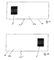
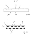
- FIG. 1 a shows in plan view a security document 1 in the form of a banknote with a security element 2 in reflected light.
- the banknote has a translucent carrier substrate 10 made of paper.
- the security element 2 is adhesively bonded in the form of a film element which comprises a layer 2a of aluminum simulating at least one first watermark.
- FIG. 1b shows the security document 1 FIG. 1a in section A - A '.
- Figure 1c shows the security document 1 FIG. 1a seen from the second side 10b in transmitted light.
- the security element 2 the viewer sees a watermark 2 'simulated by the security element 2.
- the watermark 2 ' is composed of five wavy curved bands having different transmission characteristics.
- the two bands arranged at the top and bottom have a lower transmission than the bands enclosed by them and thus have a darker effect in transmitted light.
- the security element 2 due to the at least one first watermark simulating layer 2a in reflected light shows a closed, reflective opaque surface made of aluminum, this surface is transmitted differently light transparent and visible divided into individual areas or bands with different shades of gray. This is achieved by the fact that the at least one first watermark simulating layer 2a is formed with a different layer thickness.
- the layer thickness of the layer 2a is in the range from 10 nm to 100 nm, in particular in the range from 10 to 50 nm. Adjacent regions with different layer thickness differ by 2 nm to 50 nm, in particular from 2 to 20 nm. However, this depends significantly which material is the layer simulating the first watermark 2a is formed.
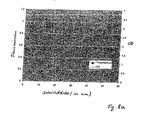
- the first watermark simulating layer 2a is formed of aluminum and it is in FIG. 8 Specifically, their transmission or optical density OD at normal illumination is shown as a function of the layer thickness (in nm) of an aluminum layer.
- the layer 2a simulating the at least one first watermark has an even smaller layer thickness than in the region of the middle band.
- the layer thicknesses of the layer 2a simulating the at least one first watermark are to be selected in each case such that different transmission or light transmission values are achieved in transmitted light. Since the observer perceives an opaque aluminum surface in reflected light, he is all the more surprised when the watermark 2 'that differs in shape and design unexpectedly shows itself in the transmitted light.
- FIG. 1 d now shows the security document 1 from the FIGS. 1 a to 1 c seen from the first page 10a in transmitted light.
- the watermark 2 ' is identical to the view from the second side 10b, only in side-reversed form.
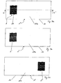
- FIG. 2a shows in plan view a security document 1 'in the form of a banknote with a security element 2 in incident light.
- the banknote has a translucent carrier substrate 10 made of paper.
- the security element 2 is imprinted in the form of a film element which comprises a layer 2a of aluminum simulating at least one first watermark.
- At least one first watermark simulating layer 2a Between the at least one first watermark simulating layer 2a and the viewer is a pattern-shaped printed translucent layer 3 with a star-shaped opening, which consists of a pigmented lacquer layer with a similar color as that adjacent support substrate 10 is formed and the actual dimensions of the, at least a first watermark simulating layer 2a conceals (here the shape of a cross, as indicated by dashed lines).
- the layer 2a simulating the first watermark is thus directly visible only in the region of the star-shaped opening in the translucent layer 3, while its remaining regions are invisible in reflected light.
- FIG. 2b shows the security document 1 'from FIG. 2a in section B - B '. It can be clearly seen that the star-shaped opening in the translucent layer 3 leaves only a part of the layer 2a simulating the first watermark uncovered.
- the security document 1 'from FIG. 2a a similar watermark 2 '(see Figure 1c ), as the security document 1 from FIG. 1a show, but with a cross-shaped outline.
- the security element 2 the viewer sees the watermark 2 'simulated by the security element 2.
- the security element 2 of the layer 2a simulating the at least one first watermark only shows a closed, star-shaped specular opaque surface made of aluminum, the layer 2a is subdivided into individual regions or bands with different light transmittances or gray levels when viewed through transmitted light.
- the opaque layer 2a which is opaque in incident light, is formed in regions with different layer thicknesses and / or has a multiplicity of openings whose spacing lies below 0.3 mm at least in one direction.
- the holes thus have, for example, in each case a diameter of approximately 2 to 100 ⁇ m or an area occupied by the respective hole of approximately 3 to 75 10 3 ⁇ m 2 and are in a grid with a screen width of 20 to 300 ⁇ m in the X direction and from 20 to 300 microns apart in the Y direction.
- the area fraction of the holes is between about 0.003 and 10%. Since the viewer perceives a star-shaped opaque aluminum surface in reflected light, he is all the more surprised, as in the transmitted light unexpectedly shows a different in shape and design watermark with a cross-shaped outline.
- FIG. 2a shows from the first page 10a from in transmitted light appearance similar to in Figure 1d shown, but with a cross-shaped outline.
- the simulated watermark is identical to the view from the second side 10b, only in a laterally inverted form.
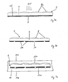
- FIG. 3a shows a further security document 1 "in the form of a banknote with a security element 2 impressed thereon.
- the layer 2a simulating the at least one first watermark is arranged by individual, in a regular grid of a screen width of 5 to 300 .mu.m, in particular from 10 to 100 .mu.m and aluminum pixels (not shown separately), which appear opaque in incident light, and between which the carrier substrate 10 is visible, at least under the microscope.
- the pixels cover 80 to 100% of the surface.
- a further reduction of the area ratio of the pixels can be achieved in that the reflection of the watermark simulating layer 2a is adapted to the reflection of the substrate or carrier substrate 10, for example by means of a scattering microstructure
- the layer 2a simulating the at least one first watermark shows a halftone or gray scale image of five in reflected light curved bands in two i different shades of gray.
- FIG. 3b shows the security document 1 "from FIG. 3a seen from the second side 10b in transmitted light. Due to different layer thicknesses of the individual pixels of the, at least one first watermark simulating layer 2a shows in the transmitted light, a first watermark 2 'with areas of different light transmission. Thus, the middle curved band is more translucent in the transmitted light than the bands above and below and also five vertical, filigree lines with high transparency are visible.
- Figure 3c shows the security document 1 "from FIG. 3a seen from the first page 10a in transmitted light.
- the viewer recognizes a second watermark 2 "which is reversed in relation to the first watermark 2 'and which does not show the five vertical, filigree lines with high light transmittance, which is realized in that the carrier substrate 10 transmits the light passing through in the area of the particularly transmissive trained filigree lines of Security elements 2 on the first page 10a scatters so much that they visually no longer appear in transmitted light.
- the security element 2 has a transparent hot-melt adhesive layer 3a, which has the at least one first watermark-simulating layer 2a and a transparent lacquer layer 3b and is adhesively bonded to the carrier substrate 10.
- the security element 2 is formed by the transfer layer of a transfer film and formed on the carrier substrate 10 in a transfer process.
- FIG. 3e shows a security document 1 "in the sectional view with an asymmetrically embedded in the support substrate 10 made of paper security element 2, which in principle as the security element 2 according to the FIGS. 3a to 3d is designed and gives a similar impression in transmitted light.
- the security element 2 is essentially not visible from any side 10a, 10b of the security document 1 "
- the security element 2 is designed as a laminating film and has a transparent lacquer layer 4a, which comprises the layer 2a simulating at least one first watermark and a transparent lacquer layer 4b
- a paper layer which scatters the transmitted light more strongly than between the security element 2 and the second side 10b
- the paper layer between the security element 2 and the first side 10a is thus for example 10 to 95% thicker in the case of a total layer thickness of the carrier substrate 10 of 50 ⁇ m to 2 mm, in particular of 50 ⁇ m to 1 mm, the embedding of the security element 2 into the carrier substrate 10 already takes place during papermaking.
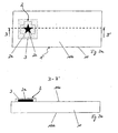
- FIG. 4a shows a further security document 1 '''in the form of a document with a security element 2, which has a viewing angle-dependent, optically variable effect in reflected light.
- the observer 100 of the security document 1 ''' shows from a first viewing direction a security element 2 with a layer 2a simulating the at least one first watermark, appearing opaque in incident light, a house being recognized as the first representation.
- the first representation is produced by diffractive first relief structures introduced into the layer 2a.
- the viewer 100 recognizes FIG. 4b likewise the security element 2 with a layer 2a which simulates the at least one first watermark and which appears opaque in incident light. From this line of sight, however, not the first representation, but due to introduced into the layer 2a, second relief structures to recognize a second representation in the form of a rose.
- the first and second relief structures are formed, for example, by diffraction gratings with different azimuth angles to one another or by different, asymmetrical relief structures, eg blazed gratings with different edge inclination.
- Figure 4c now shows the security document 1 '''from the FIGS. 4a and 4b in transmitted light and in a slightly enlarged representation. It shows neither the first nor the second representation, but a third representation in the form of a color-deposited rabbit as a watermark 2 ', which incidentally also shows from the first page 10a.
- the security element 2 is designed for realizing the security document 1 '''with a layer 2a of aluminum simulating at least one first watermark and containing diffractive structures arranged in a fine grid whose grid width is smaller than approximately 0 in at least one direction. 3 mm.
- a first group of grid surfaces contains the diffractive ones first structures, which serve in a viewing direction for generating the first representation.
- a second group of screen surfaces contains different diffractive second structures which serve to produce the second representation in a second viewing direction.
- a third group of grid surfaces contains openings which, viewed in transmitted light, increase the transmissivity in regions to produce the third representation.
- the opaque layer 2a which is opaque in incident light, has openings which are invisible to the human eye in incident light, but which are recognizable by transmitted light.
- the relative size and local frequency of the openings is varied in order to produce different halftones or gray levels in transmitted light.
- light-permeable color layers and / or transparent diffractive structures deposited with a transparent reflection layer can be arranged in order to produce color effects and / or optically variable effects in transmitted light.
- the openings have no disturbing influence on the first and second representations visible in reflected light, the grid surfaces having the openings are arranged alternately next to the diffractive grid surfaces.
- the regions of the at least one first watermark simulating layer 2a appear to be metallically reflective in incident light.
- a third structure in the form of a matt structure in the region of the perforated grid surface which has a similar scattering capacity as the carrier substrate 10, so that the regions of the layer 2a simulating the at least one first watermark correspond to the third representation are not obvious in reflected light.
- a light-absorbing diffractive fourth structure may also be present in the regions of the layer 2a simulating the at least one first watermark, which are to be assigned to the third representation, so that it appears dark in incident light.
- At least one translucent or transparent color layer is preferably arranged in the register to the openings, which in the incident light is hidden behind the layer 2a simulating at least one first watermark, but can be seen in the transmitted light and the third one Representation color or at least gives colored areas, where one or more colors may be present.
- a fourth group of grid areas with the third structures and a fifth group of grid areas with the fourth structures are occupied, thus providing a fourth and a fifth representation of the security element 2 in addition to the first, second and third representations which are formed in incident light from the third and fourth or third and fifth group of grid surfaces.
- a filigree Kinegram ® can be superimposed on the effects, which has little effect on the watermark effect and serves to distract the eye from the grid and hide it.
- the raster areas of the first to third group of raster areas are here preferably arranged alternately according to a regular raster, for example in the sequence, raster area of the first group, raster area of the second group, raster area of the third group, raster area of the first group, etc. in which the sequence repeatedly, less than 0,3 mm is chosen.
- FIG. 5a shows another security document 1 '''in the form of a document with a security element 2 (see also FIG. 5c ), which is embedded in the support substrate 10 of light-diffusing paper adjacent to the surface and, seen in transmitted light from the first side 10a, simulates the presence of a three-dimensional watermark 2 '.
- the security element 2 has at least two layers 2a ', 2a "of opaque, black-colored lacquer that simulate at least one first watermark (see FIG. 5d ), which are arranged spaced apart by a spacer film 5 made of plastic film, which acts as a filter for light in certain directions, and allows scattered light of only a certain angular range to arrive from the second side 10b.
- the two layers 2a ', 2a "simulating the at least one first watermark are each provided with openings, the openings being superimposed with one another in such a way that different regions of the security element 2 allow light to pass through in the transmitted light depending on the viewing angle according to a first viewing angle
- FIG. 5a a first three-dimensional representation, here a folded band.
- the security document 1 '''according to FIG. 5b viewed from a different angle in transmitted light, so shows the three-dimensional volume from another perspective due to the shift or change in position of the translucent areas.
- the change in perspective can be continuously observable or erratic as the angle of view changes.
- FIG. 5c shows the security document FIG. 5a and the embedded in the support substrate 10 security element 2 in a simplified form in cross section.
- FIG. 5d shows the security element 2 FIG. 5c alone and in an enlarged view in cross section. It shows the spacer layer 5, which has on each side in each case one of the at least one first watermark simulating layers 2a ', 2a ", which are each provided with openings through which passes depending on the acting as a filter spacer layer 5 light certain angular orientation Furthermore, an optically variable element 6 in the form of a volume hologram, amplitude hologram or a diffractive surface structure is present, which is very good in transmitted light but substantially indistinguishable in incident light.
- FIG. 6a shows another security document 1 with a embedded in a support substrate 10 of light-scattering paper adjacent to the surface security element which seen in transmitted light from the first side 10a, the presence of a moving watermark 2 'simulated when the viewing angle is changed.
- the security element points, as already from the principle in the FIGS. 5a to 5d shown, at least two, at least a first watermark simulating layers, which are spaced apart by a spacer acting as a filter and each provided with openings, wherein the openings are superposed with each other such that in the transmitted light depending on the viewing angle different areas of the security element light let through.
- FIG. 6b shows the security document 1 FIG. 6a also in transmitted light, but from a different angle. It shows up due to the shift or change in position of the translucent areas, the watermark 2 in a second representation, or the annulus in a different spatial orientation. In this case, the change in the position of the circular ring with change in the angle of view can be continuously observable or take place abruptly.
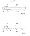
- Figure 7a shows the production of a security element 2 according to FIG. 7b for generating in cross-section a watermark effect visible only on one side of a security document.
- a film carrier 7 made of transparent PET with a layer thickness in the range of 12 to 50 ⁇ m is covered on one side with a UV-curing replication lacquer layer 8 and replicated in these microlenses 8a.
- the microlenses 8a are preferably of refractive design and have a thickness or structure depth of usually 2 to 50 ⁇ m and a diameter (seen perpendicular to the plane of the replication lacquer layer 8) of usually 5 to 100 ⁇ m.
- a metal layer 12 made of aluminum with a layer thickness of 50 nm is applied over the entire surface, in which information, in particular in the form of a € -character is introduced.
- the information is formed by covering the metal layer 12 formed over the entire area with a positive photoresist layer 9 on its side facing away from the film carrier 7.
- a UV exposure (see arrows) is performed from the side of the microlenses 8a. The UV light strikes and is focused by the microlenses 8a, so that a single light beam leaves the replication lacquer layer 8 per microlens 8a.
- the light beams pass through the film carrier 7 to the metal layer 12 and - due to a sufficient transmission of the 50 nm thick aluminum layer for UV radiation - therethrough to the positive photoresist layer 9.
- the exposed areas of the photoresist layer 9 are then removed in a washing process and the exposed areas the metal layer 12 removed by etching. Openings 11 are formed in the metal layer which are aligned in perfect registry with the microlenses 8a.
- the photoresist layer 9 is removed and the apertured metal layer 12, which has now become a first watermark simulating layer 2a, is exposed (see figure 7b ).
- the openings in the metal layer can also be produced by laser ablation, whereby a metal layer of aluminum in a layer thickness of 20 nm or a layer of tellurium in a layer thickness of 50 nm has proved successful.
- FIG. 7b shows that according to Figure 7a produced security element 2 in cross section, which can simulate embedded in a support substrate of a security document, a watermark with a particularly unusual optical effect.
- FIG. 7c now shows in cross section the security element 2 according to FIG. 7b which has been completely embedded in a carrier substrate 10 of a security document made of paper and glued on both sides with this.
- the carrier substrate 10 is comparatively weakly scattering and thin.
- a transparent adhesive layer 13a, 13b is present on both sides of the security element 2 over the entire area or only partially (for example in the form of a line or dot matrix).
- the layer thickness of the adhesive layer 13b, which is arranged adjacent to the microlenses 8a, is negligibly small with respect to the structural depth of the microlenses 8a to choose, so that the optical effect of the security element 2 is not impaired.
- the adhesive layer 13a adjacent to the first watermark simulating layer 2a can be made substantially thicker.
- the security element 2 is visible in reflected light neither from the first side 10a nor from the second side 10b of the carrier substrate 10.
- the viewer From the first side 10a of the carrier substrate 10, the viewer sees in transmitted light a first watermark with a slightly dynamic movement effect, which conveys information in the form of a € symbol, after the layer 2a simulating the first watermark through the openings 11 is only a part lets in the incoming light. Seen from the second side 10b, however, the viewer does not show any watermark in the transmitted light, since the lenses cause all incident light to be ignited and to pass through the openings 11.
- the subsequent material of the carrier substrate 10 evenly disperses the collimated light before the light comes to the observer's eye, so that, to the astonishment of the observer, viewed from the second side 10b, none Brightness differences or no watermark in the carrier substrate 10 can be perceived.
- FIG. 8a shows a diagram of the dependence of the transmission or optical density OD of an aluminum layer of the layer thickness d (in nm) under normal illumination.
- the viewer perceives the aluminum layer as translucent if a transmission of greater than 10%, in particular greater than 20%, is present. This is the case for aluminum with a layer thickness of up to about 10 to 15 nm.
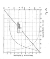
- FIG. 8b shows a diagram of the dependence of the transmission / reflection or the optical density OD of a silver layer of the layer thickness d (in nm) under normal illumination.
- the viewer perceives the silver layer as translucent if a transmission of greater than 10%, in particular greater than 20%, is present. This is the case for silver with a layer thickness of up to about 19 to 27 nm.
- the result for a layer thickness of 40 nm is a transmission of less than 10%, ie an opaque layer.
Landscapes
- Business, Economics & Management (AREA)
- Accounting & Taxation (AREA)
- Finance (AREA)
- Credit Cards Or The Like (AREA)
- Inspection Of Paper Currency And Valuable Securities (AREA)
- Diffracting Gratings Or Hologram Optical Elements (AREA)
- Transition And Organic Metals Composition Catalysts For Addition Polymerization (AREA)
Priority Applications (1)
| Application Number | Priority Date | Filing Date | Title |
|---|---|---|---|
| PL08707586T PL2114673T3 (pl) | 2007-02-07 | 2008-02-07 | Dokument bezpieczny |
Applications Claiming Priority (2)
| Application Number | Priority Date | Filing Date | Title |
|---|---|---|---|
| DE102007005884.7A DE102007005884B4 (de) | 2007-02-07 | 2007-02-07 | Sicherheitsdokument |
| PCT/EP2008/000924 WO2008095696A1 (de) | 2007-02-07 | 2008-02-07 | Sicherheitsdokument |
Publications (2)
| Publication Number | Publication Date |
|---|---|
| EP2114673A1 EP2114673A1 (de) | 2009-11-11 |
| EP2114673B1 true EP2114673B1 (de) | 2011-03-23 |
Family
ID=39430777
Family Applications (1)
| Application Number | Title | Priority Date | Filing Date |
|---|---|---|---|
| EP08707586A Revoked EP2114673B1 (de) | 2007-02-07 | 2008-02-07 | Sicherheitsdokument |
Country Status (11)
| Country | Link |
|---|---|
| US (1) | US8403368B2 (pl) |
| EP (1) | EP2114673B1 (pl) |
| CN (1) | CN101610907B (pl) |
| AT (1) | ATE502773T1 (pl) |
| AU (1) | AU2008213375B2 (pl) |
| DE (2) | DE102007005884B4 (pl) |
| ES (2) | ES2363878T3 (pl) |
| PL (1) | PL2114673T3 (pl) |
| RU (1) | RU2448840C2 (pl) |
| UA (1) | UA100683C2 (pl) |
| WO (1) | WO2008095696A1 (pl) |
Families Citing this family (49)
| Publication number | Priority date | Publication date | Assignee | Title |
|---|---|---|---|---|
| GB2437939B (en) * | 2006-05-08 | 2008-03-26 | Rue De Int Ltd | Improvements in security substrates |
| DE102007005884B4 (de) | 2007-02-07 | 2022-02-03 | Leonhard Kurz Stiftung & Co. Kg | Sicherheitsdokument |
| DE102008046511A1 (de) * | 2008-09-10 | 2010-03-11 | Giesecke & Devrient Gmbh | Darstellungsanordnung |
| FR2940179B1 (fr) * | 2008-12-23 | 2017-06-02 | Arjowiggins | Document de securite comportant au moins une image combinee et un moyen de revelation, et procede associe. |
| FR2942244B1 (fr) * | 2009-02-16 | 2011-04-15 | Arjowiggins Security | Procede pour creer une animation visuelle sur un support |
| DE102009056934A1 (de) | 2009-12-04 | 2011-06-09 | Giesecke & Devrient Gmbh | Sicherheitselement, Wertdokument mit einem solchen Sicherheitselement sowie Herstellungsverfahren eines Sicherheitselementes |
| DE102010047250A1 (de) * | 2009-12-04 | 2011-06-09 | Giesecke & Devrient Gmbh | Sicherheitselement, Wertdokument mit einem solchen Sicherheitselement sowie Herstellungsverfahren eines Sicherheitselementes |
| FR2968239B1 (fr) * | 2010-12-07 | 2012-12-21 | Hologram Ind | Produit securise et methode de fabrication dudit produit securise |
| DE102010054760A1 (de) * | 2010-12-16 | 2012-02-16 | Giesecke & Devrient Gmbh | Sicherheitselement, Verfahren zum Herstellen desselben und Datenträger |
| US9708773B2 (en) | 2011-02-23 | 2017-07-18 | Crane & Co., Inc. | Security sheet or document having one or more enhanced watermarks |
| FR2974930B1 (fr) * | 2011-05-03 | 2013-11-08 | Media Relief | Procede de fabrication d'une image iridescente, image obtenue et dispositif la comprenant, programme associe |
| DE102011100979A1 (de) * | 2011-05-10 | 2012-11-15 | Giesecke & Devrient Gmbh | Sicherheitselement und mit demselben ausgestatteter Datenträger |
| DE102011108242A1 (de) | 2011-07-21 | 2013-01-24 | Giesecke & Devrient Gmbh | Optisch variables Element, insbesondere Sicherheitselement |
| CN102903298B (zh) * | 2011-07-25 | 2015-08-05 | 中钞特种防伪科技有限公司 | 具有表面微浮雕结构的金属镀层防伪膜 |
| WO2013028534A1 (en) | 2011-08-19 | 2013-02-28 | Visual Physics, Llc | Optionally transferable optical system with a reduced thickness |
| EP2581422A1 (en) * | 2011-10-11 | 2013-04-17 | Sicpa Holding Sa | Ink coatings for security documents to prevent forgery by means of heat sensitive erasable ink |
| AU2011101567B4 (en) * | 2011-11-30 | 2012-08-09 | Innovia Security Pty Ltd | Diffractive device |
| JP6213465B2 (ja) * | 2012-06-15 | 2017-10-18 | 凸版印刷株式会社 | 偽造防止用紙 |
| JP6053932B2 (ja) | 2012-08-17 | 2016-12-27 | ビジュアル フィジクス エルエルシー | 微細構造を最終基板に転写するプロセス |
| EP3427968B2 (en) | 2013-03-12 | 2023-03-01 | Toppan Printing Co., Ltd. | Display |
| ES2728508T3 (es) | 2013-03-15 | 2019-10-25 | Visual Physics Llc | Dispositivo de seguridad óptico |
| US9873281B2 (en) | 2013-06-13 | 2018-01-23 | Visual Physics, Llc | Single layer image projection film |
| BR112016004827A8 (pt) * | 2013-09-04 | 2020-02-11 | Lumenco Llc | mapeamento de pixel e impressão para conjuntos de microlente para alcançar ativação de eixo geométrico duplo de imagens |
| EP4163888B1 (en) * | 2013-12-03 | 2024-07-03 | Crane & Co., Inc. | A security sheet or document having one or more enhanced watermarks |
| US10766292B2 (en) | 2014-03-27 | 2020-09-08 | Crane & Co., Inc. | Optical device that provides flicker-like optical effects |
| CA2943987A1 (en) | 2014-03-27 | 2015-10-01 | Visual Physics, Llc | An optical device that produces flicker-like optical effects |
| RU2557565C1 (ru) * | 2014-04-23 | 2015-07-27 | Федеральное Государственное Унитарное Предприятие "Гознак" (Фгуп "Гознак") | Многослойное изделие, защищенное от подделки (варианты), и ценный документ на его основе |
| RU2561413C1 (ru) * | 2014-04-23 | 2015-08-27 | Федеральное Государственное Унитарное Предприятие "Гознак" (Фгуп "Гознак") | Многослойный композиционный элемент на основе бумаги и ценный документ, защищенный от подделки |
| WO2015183243A1 (en) * | 2014-05-27 | 2015-12-03 | Rolith, Inc. | Anti-counterfeiting features and methods of fabrication and detection |
| ES3014185T3 (en) | 2014-07-17 | 2025-04-21 | Visual Physics Llc | An improved polymeric sheet material for use in making polymeric security documents such as bank notes |
| US10385514B1 (en) | 2014-12-30 | 2019-08-20 | Idemia Identity & Security USA LLC | Identification document with dynamic window |
| US10189292B2 (en) | 2015-02-11 | 2019-01-29 | Crane & Co., Inc. | Method for the surface application of a security device to a substrate |
| EP3150400A1 (de) * | 2015-10-02 | 2017-04-05 | Hueck Folien Gesellschaft m.b.H. | Verfahren zur herstellung eines sicherheitselements |
| DE102015015731A1 (de) * | 2015-12-01 | 2017-06-01 | Giesecke & Devrient Gmbh | Sicherheitselement und mit demselben ausgestatteter Datenträger |
| FR3046111B1 (fr) * | 2015-12-29 | 2022-03-25 | Arjowiggins Security | Article securise comportant une trame de revelation et une image combinee |
| US11434003B2 (en) * | 2016-06-08 | 2022-09-06 | The Boeing Company | Drone deterrence system, method, and assembly |
| US9861883B1 (en) * | 2016-06-17 | 2018-01-09 | Mohawk Fine Papers Inc. | Secure substrate for scratch-off products |
| EP3576956A1 (en) * | 2017-02-02 | 2019-12-11 | Fedrigoni S.p.A. | Double metal security element having transparent pattern |
| ES2922024T3 (es) | 2017-02-10 | 2022-09-06 | Crane & Co Inc | Dispositivo óptico de seguridad legible por máquina |
| GB2562262B (en) * | 2017-05-10 | 2019-12-11 | De La Rue Int Ltd | Security devices and methods for their manufacture |
| RU2676932C1 (ru) * | 2018-02-07 | 2019-01-11 | Сергей Николаевич Полушкин | Устройство для идентификации и индивидуализации и способ его изготовления |
| DE102018003603A1 (de) * | 2018-05-03 | 2019-11-07 | Giesecke+Devrient Currency Technology Gmbh | Sicherheitselement, Datenträger und Verwendung |
| DE102018005474A1 (de) * | 2018-07-09 | 2020-01-09 | Giesecke+Devrient Currency Technology Gmbh | Optisch variables Sicherheitselement mit reflektivem Flächenbereich |
| FR3105088B1 (fr) * | 2019-12-20 | 2021-12-24 | Oberthur Fiduciaire Sas | Structure optique à effet de relief |
| AT523814B1 (de) * | 2020-05-08 | 2022-08-15 | Hueck Folien Gmbh | Sicherheitselement |
| DE102020125128A1 (de) * | 2020-09-25 | 2022-03-31 | Leonhard Kurz Stiftung & Co. Kg | Mehrschichtkörper und Verfahren zur Herstellung eines Mehrschichtkörpers |
| DE102021111065A1 (de) | 2021-04-29 | 2022-11-03 | Leuchtstoffwerk Breitungen Gmbh | Sicherheitselement für Wertgegenstände mit in nur in einer Richtung wirkendem Wasserzeichen |
| DE102021005814A1 (de) | 2021-11-23 | 2023-05-25 | Giesecke+Devrient Currency Technology Gmbh | Durchsichtssicherheitselement, Datenträger und Herstellungsverfahren |
| DE102022000785A1 (de) | 2022-03-07 | 2023-09-07 | Giesecke+Devrient Currency Technology Gmbh | Sicherheitselement für ein Wertdokument, Wertdokument und Verfahren zur Herstellung eines Sicherheitselements |
Family Cites Families (20)
| Publication number | Priority date | Publication date | Assignee | Title |
|---|---|---|---|---|
| US5449200A (en) * | 1993-06-08 | 1995-09-12 | Domtar, Inc. | Security paper with color mark |
| AUPO260296A0 (en) | 1996-09-26 | 1996-10-24 | Reserve Bank Of Australia | Banknotes incorporating security devices |
| DE19739193B4 (de) | 1997-09-08 | 2006-08-03 | Giesecke & Devrient Gmbh | Verfahren zur Herstellung von Sicherheitsfolien für Wertpapiere |
| US20030137145A1 (en) * | 1999-01-08 | 2003-07-24 | John Fell | Authentication means |
| DE10047450A1 (de) | 2000-09-21 | 2002-04-11 | Orga Kartensysteme Gmbh | Erzeugnis mit einem Sicherheitselement |
| DK1330368T3 (da) | 2000-11-04 | 2004-09-27 | Kurz Leonhard Fa | Plastlegeme udformet som folie, fx transferfolie eller laminatfolie, eller forsynet med en sådan folie samt fremgangsmåde til fremstilling af et flerfarvebillede på eller i et sådant plastlegeme |
| DE10154051A1 (de) * | 2000-11-04 | 2002-06-20 | Kurz Leonhard Fa | Mehrschichtenbild in einem mindestens zwei Schichten aufweisenden Schichtenaufbau einer Beschichtung oder einer Folie sowie Verfahren zur Herstellung eines solchen Mehrschichtenbildes |
| FR2818672B1 (fr) | 2000-12-22 | 2003-02-21 | Arjo Wiggins Sa | Papier de securite comportant une zone reagissant aux solvants apolaires |
| CA2399356C (en) | 2001-09-07 | 2012-01-24 | Kba-Giori S.A. | Control element for printed articles |
| ITMI20011889A1 (it) | 2001-09-10 | 2003-03-10 | Elmiva S A S Di Walter Mantega | Procedimento contro la falsificazione e la contraffazione di documenti di valore in particolare banconote |
| DE10150293B4 (de) * | 2001-10-12 | 2005-05-12 | Ovd Kinegram Ag | Sicherheitselement |
| DE10226114A1 (de) * | 2001-12-21 | 2003-07-03 | Giesecke & Devrient Gmbh | Sicherheitselement für Sicherheitspapiere und Wertdokumente |
| DE10256832A1 (de) | 2002-12-04 | 2004-06-24 | Giesecke & Devrient Gmbh | Sicherheitsfolie und Verfahren zur Herstellung derselben |
| DE10349000A1 (de) | 2003-10-17 | 2005-05-19 | Giesecke & Devrient Gmbh | Sicherheitselement mit Farbkippeffekt |
| DE10356146A1 (de) | 2003-12-02 | 2005-06-30 | Giesecke & Devrient Gmbh | Datenträger und Verfahren zu seiner Herstellung |
| GB0409747D0 (en) * | 2004-04-30 | 2004-06-09 | Rue De Int Ltd | Improvements in substrates incorporating security devices |
| DE102004042136B4 (de) | 2004-08-30 | 2006-11-09 | Ovd Kinegram Ag | Metallisiertes Sicherheitselement |
| DE102005028162A1 (de) | 2005-02-18 | 2006-12-28 | Giesecke & Devrient Gmbh | Sicherheitselement und Verfahren zu seiner Herstellung |
| US20060202469A1 (en) * | 2005-03-10 | 2006-09-14 | Neil Teitelbaum | Financial instrument having indicia related to a security feature thereon |
| DE102007005884B4 (de) | 2007-02-07 | 2022-02-03 | Leonhard Kurz Stiftung & Co. Kg | Sicherheitsdokument |
-
2007
- 2007-02-07 DE DE102007005884.7A patent/DE102007005884B4/de active Active
-
2008
- 2008-02-07 RU RU2009133326/02A patent/RU2448840C2/ru not_active IP Right Cessation
- 2008-02-07 PL PL08707586T patent/PL2114673T3/pl unknown
- 2008-02-07 US US12/449,459 patent/US8403368B2/en not_active Expired - Fee Related
- 2008-02-07 AU AU2008213375A patent/AU2008213375B2/en active Active
- 2008-02-07 AT AT08707586T patent/ATE502773T1/de active
- 2008-02-07 ES ES08707586T patent/ES2363878T3/es active Active
- 2008-02-07 UA UAA200908383A patent/UA100683C2/ru unknown
- 2008-02-07 CN CN2008800042469A patent/CN101610907B/zh active Active
- 2008-02-07 ES ES08707598T patent/ES2363879T3/es active Active
- 2008-02-07 DE DE502008002941T patent/DE502008002941D1/de active Active
- 2008-02-07 EP EP08707586A patent/EP2114673B1/de not_active Revoked
- 2008-02-07 WO PCT/EP2008/000924 patent/WO2008095696A1/de not_active Ceased
Also Published As
| Publication number | Publication date |
|---|---|
| ATE502773T1 (de) | 2011-04-15 |
| US20100001508A1 (en) | 2010-01-07 |
| CN101610907B (zh) | 2013-08-21 |
| DE502008002941D1 (de) | 2011-05-05 |
| DE102007005884B4 (de) | 2022-02-03 |
| ES2363878T3 (es) | 2011-08-18 |
| RU2009133326A (ru) | 2011-03-20 |
| UA100683C2 (ru) | 2013-01-25 |
| CN101610907A (zh) | 2009-12-23 |
| WO2008095696A1 (de) | 2008-08-14 |
| AU2008213375B2 (en) | 2011-09-01 |
| PL2114673T3 (pl) | 2011-07-29 |
| DE102007005884A1 (de) | 2008-08-14 |
| EP2114673A1 (de) | 2009-11-11 |
| US8403368B2 (en) | 2013-03-26 |
| RU2448840C2 (ru) | 2012-04-27 |
| AU2008213375A1 (en) | 2008-08-14 |
| ES2363879T3 (es) | 2011-08-18 |
Similar Documents
| Publication | Publication Date | Title |
|---|---|---|
| EP2114673B1 (de) | Sicherheitsdokument | |
| EP3339048B1 (de) | Sicherheitselement mit reflektivem flächenbereich | |
| DE102007023560B4 (de) | Mehrschichtkörper | |
| EP1800271B1 (de) | Sicherheitsdokument | |
| DE10328760B4 (de) | Optisches Sicherheitselement | |
| EP1979768B1 (de) | Mehrschichtkörper mit mikrolinsen-anordnung | |
| EP2040934B2 (de) | Sicherheitselement | |
| EP2117840B1 (de) | Sicherheitselement für ein sicherheitsdokument und verfahren zu seiner herstellung | |
| EP1853763B1 (de) | Sicherheitselement und verfahren zu seiner herstellung | |
| EP2091756B1 (de) | Durchsichtssicherheitselement mit mikrostrukturen | |
| EP1644871B1 (de) | Optisches sicherheitselement und system zur visualisierung von versteckten informationen | |
| EP2198407A1 (de) | Gitterbild | |
| DE112011102365T5 (de) | Optisch variable Einrichtung | |
| DE102008062475A1 (de) | Sicherheitselement und Sicherheitspapier | |
| EP3648983B1 (de) | Optisch variable sicherheitsanordnung | |
| EP3406458B1 (de) | Sicherheitselement mit reflektivem flächenbereich | |
| DE102019003518A1 (de) | Sicherheitselement mit optisch variablem Flächenmuster |
Legal Events
| Date | Code | Title | Description |
|---|---|---|---|
| PUAI | Public reference made under article 153(3) epc to a published international application that has entered the european phase |
Free format text: ORIGINAL CODE: 0009012 |
|
| 17P | Request for examination filed |
Effective date: 20090806 |
|
| AK | Designated contracting states |
Kind code of ref document: A1 Designated state(s): AT BE BG CH CY CZ DE DK EE ES FI FR GB GR HR HU IE IS IT LI LT LU LV MC MT NL NO PL PT RO SE SI SK TR |
|
| DAX | Request for extension of the european patent (deleted) | ||
| GRAP | Despatch of communication of intention to grant a patent |
Free format text: ORIGINAL CODE: EPIDOSNIGR1 |
|
| GRAS | Grant fee paid |
Free format text: ORIGINAL CODE: EPIDOSNIGR3 |
|
| GRAA | (expected) grant |
Free format text: ORIGINAL CODE: 0009210 |
|
| AK | Designated contracting states |
Kind code of ref document: B1 Designated state(s): AT BE BG CH CY CZ DE DK EE ES FI FR GB GR HR HU IE IS IT LI LT LU LV MC MT NL NO PL PT RO SE SI SK TR |
|
| REG | Reference to a national code |
Ref country code: GB Ref legal event code: FG4D Free format text: NOT ENGLISH |
|
| REG | Reference to a national code |
Ref country code: CH Ref legal event code: NV Representative=s name: FIAMMENGHI-FIAMMENGHI Ref country code: CH Ref legal event code: EP |
|
| REG | Reference to a national code |
Ref country code: IE Ref legal event code: FG4D |
|
| REF | Corresponds to: |
Ref document number: 502008002941 Country of ref document: DE Date of ref document: 20110505 Kind code of ref document: P |
|
| REG | Reference to a national code |
Ref country code: DE Ref legal event code: R096 Ref document number: 502008002941 Country of ref document: DE Effective date: 20110505 |
|
| REG | Reference to a national code |
Ref country code: SE Ref legal event code: TRGR |
|
| REG | Reference to a national code |
Ref country code: NL Ref legal event code: T3 |
|
| PG25 | Lapsed in a contracting state [announced via postgrant information from national office to epo] |
Ref country code: LV Free format text: LAPSE BECAUSE OF FAILURE TO SUBMIT A TRANSLATION OF THE DESCRIPTION OR TO PAY THE FEE WITHIN THE PRESCRIBED TIME-LIMIT Effective date: 20110323 Ref country code: HR Free format text: LAPSE BECAUSE OF FAILURE TO SUBMIT A TRANSLATION OF THE DESCRIPTION OR TO PAY THE FEE WITHIN THE PRESCRIBED TIME-LIMIT Effective date: 20110323 Ref country code: LT Free format text: LAPSE BECAUSE OF FAILURE TO SUBMIT A TRANSLATION OF THE DESCRIPTION OR TO PAY THE FEE WITHIN THE PRESCRIBED TIME-LIMIT Effective date: 20110323 Ref country code: GR Free format text: LAPSE BECAUSE OF FAILURE TO SUBMIT A TRANSLATION OF THE DESCRIPTION OR TO PAY THE FEE WITHIN THE PRESCRIBED TIME-LIMIT Effective date: 20110624 |
|
| REG | Reference to a national code |
Ref country code: PL Ref legal event code: T3 |
|
| REG | Reference to a national code |
Ref country code: ES Ref legal event code: FG2A Ref document number: 2363878 Country of ref document: ES Kind code of ref document: T3 Effective date: 20110818 |
|
| LTIE | Lt: invalidation of european patent or patent extension |
Effective date: 20110323 |
|
| PG25 | Lapsed in a contracting state [announced via postgrant information from national office to epo] |
Ref country code: BG Free format text: LAPSE BECAUSE OF FAILURE TO SUBMIT A TRANSLATION OF THE DESCRIPTION OR TO PAY THE FEE WITHIN THE PRESCRIBED TIME-LIMIT Effective date: 20110623 Ref country code: SI Free format text: LAPSE BECAUSE OF FAILURE TO SUBMIT A TRANSLATION OF THE DESCRIPTION OR TO PAY THE FEE WITHIN THE PRESCRIBED TIME-LIMIT Effective date: 20110323 Ref country code: FI Free format text: LAPSE BECAUSE OF FAILURE TO SUBMIT A TRANSLATION OF THE DESCRIPTION OR TO PAY THE FEE WITHIN THE PRESCRIBED TIME-LIMIT Effective date: 20110323 Ref country code: NO Free format text: LAPSE BECAUSE OF FAILURE TO SUBMIT A TRANSLATION OF THE DESCRIPTION OR TO PAY THE FEE WITHIN THE PRESCRIBED TIME-LIMIT Effective date: 20110623 Ref country code: CY Free format text: LAPSE BECAUSE OF FAILURE TO SUBMIT A TRANSLATION OF THE DESCRIPTION OR TO PAY THE FEE WITHIN THE PRESCRIBED TIME-LIMIT Effective date: 20110323 |
|
| REG | Reference to a national code |
Ref country code: IE Ref legal event code: FD4D |
|
| REG | Reference to a national code |
Ref country code: HU Ref legal event code: AG4A Ref document number: E011248 Country of ref document: HU |
|
| PG25 | Lapsed in a contracting state [announced via postgrant information from national office to epo] |
Ref country code: EE Free format text: LAPSE BECAUSE OF FAILURE TO SUBMIT A TRANSLATION OF THE DESCRIPTION OR TO PAY THE FEE WITHIN THE PRESCRIBED TIME-LIMIT Effective date: 20110323 Ref country code: PT Free format text: LAPSE BECAUSE OF FAILURE TO SUBMIT A TRANSLATION OF THE DESCRIPTION OR TO PAY THE FEE WITHIN THE PRESCRIBED TIME-LIMIT Effective date: 20110725 |
|
| PG25 | Lapsed in a contracting state [announced via postgrant information from national office to epo] |
Ref country code: IS Free format text: LAPSE BECAUSE OF FAILURE TO SUBMIT A TRANSLATION OF THE DESCRIPTION OR TO PAY THE FEE WITHIN THE PRESCRIBED TIME-LIMIT Effective date: 20110723 Ref country code: RO Free format text: LAPSE BECAUSE OF FAILURE TO SUBMIT A TRANSLATION OF THE DESCRIPTION OR TO PAY THE FEE WITHIN THE PRESCRIBED TIME-LIMIT Effective date: 20110323 Ref country code: SK Free format text: LAPSE BECAUSE OF FAILURE TO SUBMIT A TRANSLATION OF THE DESCRIPTION OR TO PAY THE FEE WITHIN THE PRESCRIBED TIME-LIMIT Effective date: 20110323 |
|
| PLBI | Opposition filed |
Free format text: ORIGINAL CODE: 0009260 |
|
| PLAX | Notice of opposition and request to file observation + time limit sent |
Free format text: ORIGINAL CODE: EPIDOSNOBS2 |
|
| PG25 | Lapsed in a contracting state [announced via postgrant information from national office to epo] |
Ref country code: IE Free format text: LAPSE BECAUSE OF FAILURE TO SUBMIT A TRANSLATION OF THE DESCRIPTION OR TO PAY THE FEE WITHIN THE PRESCRIBED TIME-LIMIT Effective date: 20110323 |
|
| 26 | Opposition filed |
Opponent name: GIESECKE & DEVRIENT GMBH Effective date: 20111222 |
|
| REG | Reference to a national code |
Ref country code: DE Ref legal event code: R026 Ref document number: 502008002941 Country of ref document: DE Effective date: 20111222 |
|
| PLAF | Information modified related to communication of a notice of opposition and request to file observations + time limit |
Free format text: ORIGINAL CODE: EPIDOSCOBS2 |
|
| PLBB | Reply of patent proprietor to notice(s) of opposition received |
Free format text: ORIGINAL CODE: EPIDOSNOBS3 |
|
| BERE | Be: lapsed |
Owner name: LEONHARD KURZ STIFTUNG & CO. K.G. Effective date: 20120228 |
|
| PG25 | Lapsed in a contracting state [announced via postgrant information from national office to epo] |
Ref country code: MC Free format text: LAPSE BECAUSE OF NON-PAYMENT OF DUE FEES Effective date: 20120229 |
|
| PG25 | Lapsed in a contracting state [announced via postgrant information from national office to epo] |
Ref country code: BE Free format text: LAPSE BECAUSE OF NON-PAYMENT OF DUE FEES Effective date: 20120228 |
|
| PG25 | Lapsed in a contracting state [announced via postgrant information from national office to epo] |
Ref country code: MT Free format text: LAPSE BECAUSE OF FAILURE TO SUBMIT A TRANSLATION OF THE DESCRIPTION OR TO PAY THE FEE WITHIN THE PRESCRIBED TIME-LIMIT Effective date: 20110323 |
|
| PG25 | Lapsed in a contracting state [announced via postgrant information from national office to epo] |
Ref country code: TR Free format text: LAPSE BECAUSE OF FAILURE TO SUBMIT A TRANSLATION OF THE DESCRIPTION OR TO PAY THE FEE WITHIN THE PRESCRIBED TIME-LIMIT Effective date: 20110323 |
|
| PG25 | Lapsed in a contracting state [announced via postgrant information from national office to epo] |
Ref country code: LU Free format text: LAPSE BECAUSE OF NON-PAYMENT OF DUE FEES Effective date: 20120207 |
|
| PLCK | Communication despatched that opposition was rejected |
Free format text: ORIGINAL CODE: EPIDOSNREJ1 |
|
| APBM | Appeal reference recorded |
Free format text: ORIGINAL CODE: EPIDOSNREFNO |
|
| APBP | Date of receipt of notice of appeal recorded |
Free format text: ORIGINAL CODE: EPIDOSNNOA2O |
|
| APAH | Appeal reference modified |
Free format text: ORIGINAL CODE: EPIDOSCREFNO |
|
| APBQ | Date of receipt of statement of grounds of appeal recorded |
Free format text: ORIGINAL CODE: EPIDOSNNOA3O |
|
| REG | Reference to a national code |
Ref country code: FR Ref legal event code: PLFP Year of fee payment: 9 |
|
| REG | Reference to a national code |
Ref country code: FR Ref legal event code: PLFP Year of fee payment: 10 |
|
| PLAB | Opposition data, opponent's data or that of the opponent's representative modified |
Free format text: ORIGINAL CODE: 0009299OPPO |
|
| R26 | Opposition filed (corrected) |
Opponent name: GIESECKE+DEVRIENT CURRENCY TECHNOLOGY GMBH Effective date: 20111222 |
|
| REG | Reference to a national code |
Ref country code: FR Ref legal event code: PLFP Year of fee payment: 11 |
|
| PGFP | Annual fee paid to national office [announced via postgrant information from national office to epo] |
Ref country code: PL Payment date: 20181214 Year of fee payment: 12 |
|
| PGFP | Annual fee paid to national office [announced via postgrant information from national office to epo] |
Ref country code: NL Payment date: 20190219 Year of fee payment: 12 |
|
| APAH | Appeal reference modified |
Free format text: ORIGINAL CODE: EPIDOSCREFNO |
|
| PGFP | Annual fee paid to national office [announced via postgrant information from national office to epo] |
Ref country code: GB Payment date: 20200225 Year of fee payment: 13 Ref country code: SE Payment date: 20200224 Year of fee payment: 13 Ref country code: DE Payment date: 20200221 Year of fee payment: 13 Ref country code: IT Payment date: 20200221 Year of fee payment: 13 Ref country code: AT Payment date: 20200218 Year of fee payment: 13 |
|
| PGFP | Annual fee paid to national office [announced via postgrant information from national office to epo] |
Ref country code: CZ Payment date: 20200129 Year of fee payment: 13 Ref country code: CH Payment date: 20200224 Year of fee payment: 13 |
|
| REG | Reference to a national code |
Ref country code: DE Ref legal event code: R064 Ref document number: 502008002941 Country of ref document: DE Ref country code: DE Ref legal event code: R103 Ref document number: 502008002941 Country of ref document: DE |
|
| APBU | Appeal procedure closed |
Free format text: ORIGINAL CODE: EPIDOSNNOA9O |
|
| PGFP | Annual fee paid to national office [announced via postgrant information from national office to epo] |
Ref country code: FR Payment date: 20200220 Year of fee payment: 13 |
|
| RDAF | Communication despatched that patent is revoked |
Free format text: ORIGINAL CODE: EPIDOSNREV1 |
|
| STAA | Information on the status of an ep patent application or granted ep patent |
Free format text: STATUS: PATENT REVOKED |
|
| RDAG | Patent revoked |
Free format text: ORIGINAL CODE: 0009271 |
|
| REG | Reference to a national code |
Ref country code: CH Ref legal event code: PL |
|
| REG | Reference to a national code |
Ref country code: FI Ref legal event code: MGE |
|
| 27W | Patent revoked |
Effective date: 20200626 |
|
| GBPR | Gb: patent revoked under art. 102 of the ep convention designating the uk as contracting state |
Effective date: 20200626 |
|
| REG | Reference to a national code |
Ref country code: SE Ref legal event code: ECNC |
|
| REG | Reference to a national code |
Ref country code: AT Ref legal event code: MA03 Ref document number: 502773 Country of ref document: AT Kind code of ref document: T Effective date: 20200626 |
|
| PG25 | Lapsed in a contracting state [announced via postgrant information from national office to epo] |
Ref country code: ES Free format text: LAPSE BECAUSE OF NON-PAYMENT OF DUE FEES Effective date: 20200208 |
|
| PG25 | Lapsed in a contracting state [announced via postgrant information from national office to epo] |
Ref country code: ES Free format text: LAPSE BECAUSE OF NON-PAYMENT OF DUE FEES Effective date: 20200208 |
|
| PG25 | Lapsed in a contracting state [announced via postgrant information from national office to epo] |
Ref country code: NL Free format text: LAPSE BECAUSE OF THE APPLICANT RENOUNCES Effective date: 20200229 |
|
| PG25 | Lapsed in a contracting state [announced via postgrant information from national office to epo] |
Ref country code: NL Free format text: LAPSE BECAUSE OF THE APPLICANT RENOUNCES Effective date: 20200229 |
|
| PG25 | Lapsed in a contracting state [announced via postgrant information from national office to epo] |
Ref country code: PL Free format text: LAPSE BECAUSE OF NON-PAYMENT OF DUE FEES Effective date: 20200207 |